Article

A Two-Step Phase Compensation-Based Imaging Method for GNSS-Based Bistatic SAR: Extraction and Compensation of Ionospheric Phase Scintillation

School of Electronics and Information Engineering, Beihang University, Beijing 100191, China
*
Author to whom correspondence should be addressed.
Remote Sens. 2024, 16(13), 2345; https://doi.org/10.3390/rs16132345
Submission received: 10 May 2024 / Revised: 19 June 2024 / Accepted: 24 June 2024 / Published: 27 June 2024
(This article belongs to the Special Issue SAR Data Processing and Applications Based on Machine Learning Method)

Abstract

:
The GNSS-based bistatic SAR (GNSS-BSAR) system has emerged as a hotspot due to its low power consumption, nice concealment, and worldwide reach. However, the weak landing power density of the GNSS signal often necessitates prolonged integration to achieve an adequate signal-to-noise ratio (SNR). In this case, the effects of the receiver’s time-frequency errors and atmospheric disturbances are significant and cannot be ignored. Therefore, we propose an ionospheric scintillation compensation-based imaging scheme for dual-channel GNSS-BSAR system. This strategy first extracts the reference phase, which contains the ionospheric phase scintillation and other errors. Subsequently, the azimuth phase of the target is divided into difference phase and reference phase. We apply the two-step phase compensation to eliminate Doppler phase errors, thus achieving precise focusing of SAR images. Three sets of experiments using the GPS L5 signal as the illuminator were conducted, coherently processing a 1.5 km by 0.8 km scene about 300 s. The comparative results show that the proposed method exhibited better focusing performance, avoiding the practical challenges encountered by traditional autofocus algorithms. Additionally, ionospheric phase scintillation extracted at different times of the day suggest diurnal variations, preliminary illustrating the potential of this technology for ionospheric-related studies.

1. Introduction

The evolution of Synthetic Aperture Radar (SAR) technology is progressing from monostatic to bistatic configurations, driven by the need for more diverse remote sensing applications [1,2]. In addition to providing navigation, positioning, and timing functions, the Global Navigation Satellite System (GNSS) also offers high-quality microwave sources with all-day coverage for most regions of the world, which have been considered illuminators of opportunity for passive radar applications [3,4]. GNSS-based bistatic SAR (GNSS-BSAR) imaging is a research hotspot in the secondary utilization of GNSS signals [5,6,7,8,9]. This application can use numerous GNSS satellites as transmitters to perform radar function by receiving reflected echoes from the target area and obtain a two-dimensional radar image.
Utilizing navigation satellites as the radar transmitters offers several advantages. The global coverage of the satellites ensures continuous illumination of any point on Earth’s surface by GNSS signals. This capability is particularly useful for monitoring the safety of urban and suburban zones. In addition, the uniform distribution of GNSS satellites in space is conducive to selecting the optimal bistatic configuration to obtain appropriate radar resolution capabilities. Due to the timing function of navigation satellite systems, they have good time synchronization characteristics, which provides great potential for multi-static radar operations. The system offers cost-effectiveness as it requires only the design of the receiver, whose hardware is similar to that of standard navigation receiver chipsets. By modifying the signal processing algorithms within these chipsets, the device can be transformed into a low-cost radar receiver. The GNSS-BSAR system also has the characteristics of light weight, low power consumption, silent operation, and no electromagnetic pollution. This topic has been thoroughly investigated both theoretically and experimentally for many years, confirming its potential for radar imaging and its capability for area monitoring [10,11,12,13,14,15,16,17,18].
However, GNSS signals are not naturally suited for radar applications, presenting several challenges to be faced. The main problem is the extremely low landing power density of these signals, so in communication systems, the reflected signal of the target is usually considered as an undesirable multipath signal. GNSS-BSAR systems usually require long-time energy accumulation to obtain sufficient signal-to-noise ratio (SNR). However, under the long synthetic aperture time, the time-frequency error of the receiver and the influence of atmospheric effects are amplified and cannot be ignored. Because the GNSS signal is in the L-band, the phase error caused by atmospheric effects will be significant. The Earth’s surface atmosphere is mainly divided into the troposphere and the ionosphere. The ionosphere, a plasma layer in the upper atmosphere filled with charged particles, significantly influences radio signal propagation [19,20]. Ionospheric propagation introduces nonnegligible errors into the final SAR product, manifesting as phase dispersion, attenuation, Faraday rotation, and scintillation [21]. In bistatic SAR systems, azimuth imaging deterioration mainly results from aperture decorrelation, which is always introduced by scintillation phase errors [22].
Early successful examples of GNSS-BSAR imaging appeared in [10]. Scholars from the University of Birmingham studied signal synchronization and image formation algorithms for GNSS-BSAR imaging. The efficacy and applicability of the algorithms have been validated through experimental testing, where the receiver is moving or fixed on the ground. There are also researches on multi-static operation in GNSS-SAR. Liu et al. [23] introduced a novel multi-static SAR configuration, where detailed system design, resolution analysis, and topology optimization were discussed. Santi et al. [24] explored the use of multiple satellites for bistatic and multi-static SAR acquisitions, focusing on data fusion techniques to enhance image resolution and information space. There are also studies on the impact and compensation of ionospheric effects in low-frequency spaceborne SAR imaging. Ji et al. [25] introduced an application of the phase gradient autofocus to compensate for spatially varying and anisotropic scintillation phase errors. Lin et al. [26] proposed a method integrated into the focusing process to estimate and mitigate ionospheric effects in bistatic SAR System, including imaging performance deterioration and geometric distortion.
There are few studies in the existing literature that specifically analyze the impact of atmospheric effects in GNSS-BSAR long-time imaging. Considering aforementioned problems, this paper studies the GNSS-BSAR imaging processing under long synthetic aperture time. An ionospheric scintillation compensation-based modified Back Projection (BP) imaging method is proposed for dual-channel receiving GNSS-BSAR system. This method first extracts the Doppler phase errors of the reference channel, which includes the impact of local oscillator time-frequency error of the receiver and atmospheric effects. The ionospheric scintillation phase error is isolated individually using polynomial fitting. Subsequently, the modified BP algorithm is operated, which partitions the azimuth phase of the imaging channel into difference phase and reference phase. Through two-step azimuth phase compensation, the Doppler phase errors of the imaging channel can be accurately eliminated, effectively improving the focusing accuracy of SAR images. The main contributions of this study can be summarized below:
  • Two-Step Azimuth Phase Compensation Method: To address the issue of atmospheric disturbances in GNSS-BSAR systems during long-time observations, this paper proposes a two-step azimuth phase compensation method. This strategy decomposes the azimuth phase of the imaging channel into difference and reference phases. Through phase compensation, Doppler phase errors are eliminated, and the processing results of actual data demonstrate that the proposed method achieves precise focusing in GNSS-BSAR imaging.
  • Novel Processing Mode: Unlike traditional autofocus-based error compensation algorithms, which have limitations requiring strong prominent points in the observation scene, multiple iterations for convergence, and limited capability for high-order phase error compensation, the proposed method utilizes the dual-channel receiving characteristic. It introduces a novel processing mode that directly uses the phase information extracted from the reference channel for error analysis and phase compensation, avoiding the practical challenges encountered by autofocus algorithms.
  • Potential for Ionospheric-Related Studies: By extracting ionospheric phase scintillation at different times of the day, this work preliminarily illustrates the potential of this technology for ionospheric-related studies. Moreover, the proposed method can also be adapted to other passive SAR imaging systems based on dual-channel receiving modes, demonstrating a certain level of versatility.
The rest of the paper is organized as follows. Section 2 introduces the system configuration and signal model, analyzing the impact of atmospheric effects, particularly ionospheric scintillation, on GNSS-BSAR imaging. Section 3 describes the ionospheric scintillation compensation-based modified BP imaging method, including reference channel ionospheric scintillation phase error extraction technology and precise azimuth focus through two-step azimuth phase compensation. Section 4 presents the actual data processing results using GPS L5 signal as the illuminator of opportunity to illustrate the validity of the proposed method. Section 5 analyzes the algorithm performance, evaluates the imaging results and outlines potential future research directions. Finally, Section 6 concludes the work.

2. System Model and Atmospheric Error Analysis

2.1. System Configuration

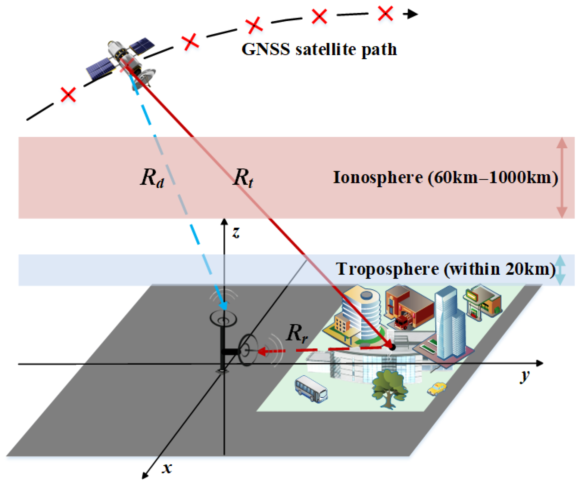
The configuration of the GNSS-based bistatic SAR (GNSS-BSAR) is illustrated in Figure 1. The system mainly relies on the motion of GNSS satellites to form the synthetic aperture. Taking GPS satellites as an example, the satellite orbit is in the Medium Earth Orbit (MEO) with an orbital altitude of 20,200 km. Since GNSS satellites are far away from the imaging area and their velocities are slower than low-orbit satellites, the velocity relative to the stationary ground scene is very small. When the receiver is placed on the ground, to obtain fine azimuth resolution, the required synthetic aperture time is very large, even on the order of hundreds of seconds.
The studied GNSS-BSAR system works in dual-channel receiving mode. The receiver is placed on a fixed platform and serves as the origin of the coordinate to generate a two-dimensional SAR image by receiving the echo of the target area. One of the channels is equipped with an omnidirectional GNSS antenna, which is used to receive direct wave signals from GNSS satellites for system synchronization (blue path in Figure 1) and is called the reference channel. The other channel is equipped with a narrow-beam antenna pointing at the target area to receive the echo for SAR imaging (red path in Figure 1), which is called the imaging channel. Since the polarization characteristic of the signal transmitted by navigation satellite is right-handed circular polarization, it can be decomposed into two linear polarization components, vertical and horizontal. After reflection from the Earth’s surface, the polarization characteristics of some electromagnetic waves become left-handed circular polarization. The specific proportion of each polarization component is related to the altitude angle of the satellite. In this paper, the receiving antenna of the imaging channel adopts left-hand circular polarization mode.

2.2. Signal Model of the GNSS-BSAR System

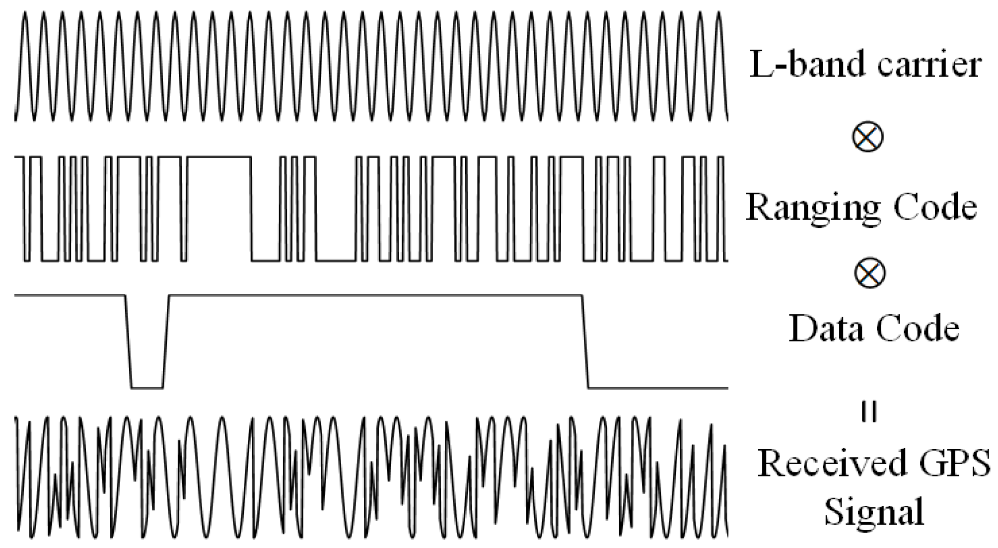
The general structure of the GNSS signal is given in Figure 2. In GNSS-BSAR system, the large signal bandwidth enables fine range resolution. Considering the capabilities of the existing experimental equipment, this work selected the GPS L5 signal as the illuminator of opportunity for both model analysis and experimental test, which can achieve a range resolution of 15 m. For navigation and positioning, GNSS signals generally have a three-layer modulation structure. The bottom layer is the L-band carrier with a frequency of 1176.45 MHz. The middle layer is the ranging code signal in the form of pseudorandom noise (PRN). The ranging code is modulated in BPSK mode, with a time length of 1 ms, a chip length of 10,230, and a bandwidth of 20.46 MHz. Similar to the pulse modulation signal in the radar system, the GPS system improves the anti-noise performance of the system through spread spectrum modulation of the ranging code. The top layer is data code. The data code is also modulated in BPSK mode, and its length is 20 times than the ranging code. The data code carries satellite navigation data, such as satellite ephemeris, time, and other information. It is crucial for navigation and positioning functions, but it is redundant for radar applications and will interfere with the Doppler phase of the signal. Therefore, it must be demodulated before performing SAR imaging.
The signal transmitted by a single GPS satellite can be expressed as:
S t = n = 0 N rect t n T p T p C t n T p D t exp j 2 π f c t
where t represents time, C · represents the ranging code (also called CA code), T p represents the equivalent pulse repetition period, and D · represents the data code. fc represents the signal carrier frequency. Since the amplitude and initial phase of the signal have no impact on the analysis, they are ignored in the equation.
The signal received by the reference channel is the delay of the GPS signal, that is:
S d t = S t R d t c = n = 0 N rect t n T p R d t / c T p C t n T p R d t c ×      D t R d t c exp j 2 π f c t R d t c
where R d t represents the distance from transmitter to receiver.
The point target echo received by the imaging channel can be expressed as:
S r t = S t R t c = n = 0 N rect t n T p R t / c T p C t n T p R t c ×     D t R t c exp j 2 π f c t R t c
where R t = R t t + R r t , R t t represents the distance from the transmitter to the target, and R r t represents the distance from the target to the receiver. R t is the total propagation distance of the reflected echo.
Utilizing the data code tracked by the reference channel, carrier demodulation and data code demodulation are performed to obtain the baseband echo signal. Since the GPS ranging code signal has a small tolerance for Doppler shifts, the Doppler center frequency of the navigation satellite relative to the receiver should be demodulated when the carrier is demodulated. The target echo can be expressed as:
S r 1 t = S r t × D t R d t c × exp j 2 π f c + f d c t = n = 0 N rect t n T p R t / c T p C t n T p R t c      exp j 2 π R t λ j 2 π f d c t
where f d c = 1 λ d R d t d t t = t c represents the Doppler center frequency of the satellite relative to the receiver, and t c represents the center time of radar observation. R d t can be calculated by the positions of the receiver and satellite. λ represents the wavelength.
Figure 3 shows the process of two-dimensional echo rearrangement. Clearly, the signal of the imaging channel always lags that of the reference channel, so there is a misalignment between the starting edge both ranging code and data code. Take the situation where the data code has a sign flip between the (n − 1)-th and n-th ranging codes in reference channel as an example. For the (n − 1)-th ranging code of the imaging channel, some of the signals located on both sides of the dotted line in Figure 3, resulting in a phase jump of ± π . However, for ground-based receiving end, the signal delay of the target echo relative to the reference channel is generally shorter. And the chip length of the data code is 20 ms. So, during multi-pulse long-time integration, the loss of SNR due to this phase jump can generally be ignored.
Let τ = t n T p in Equation (4), the two-dimensional echo matrix can be obtained:
S r 2 t , τ = rect τ R t / c T p C τ R t c exp j 2 π R t λ j 2 π f d c t
where t 0 , N T p is called slow time or azimuth time, τ 0 , T p is called fast time or range time.
Since the Doppler center frequency caused by satellite motion has been eliminated, the “stop-go” model was used in the equation, and the Doppler phase modulation within the equivalent pulse was ignored. As shown in Figure 3, with the nth pulse starting edge of the reference channel as a reference, the data with length T p in the imaging channel are read as the nth row of the two-dimensional echo matrix. The data in the nth row are a combination of the second part of the (n − 1)-th pulse and the first part of the nth pulse. Due to the periodicity of the ranging code, when pulse compression of the ranging code is finished in the frequency domain, the peak value will appear correctly at the starting edge of the nth pulse.

2.3. Analysis of Ionospheric Effects on GNSS-BSAR Imaging

The Earth’s surface is not an ideal vacuum environment. As shown in Figure 4, the troposphere is from the Earth’s surface to about 20 km, and the ionosphere is from about 60 km to 1000 km. When signals are transmitted between the antenna and the target area, the troposphere and ionosphere will introduce additional amplitude and phase errors, affecting the focusing of SAR imaging. For the studied GNSS-BSAR system, the distance between the target area and the receiver is relatively close, and the influence of atmospheric effects on the receiving path can be negligible (the red dotted line in Figure 4). The transmitting path will be affected by the ionosphere and troposphere, which will be analyzed in detail below.
The troposphere is a non-dispersive medium, which has a consistent impact on different frequencies of the signal and does not affect the range compression effect. However, differences in the geometric relationship at different azimuth time and the time variability of the troposphere will introduce different delays. For the L-band signal, the range delay is usually on the order of meters [27]. In this paper, the GPS L5 signal was used, and its range resolution was about 15 m. The range delay caused by the troposphere is less than half a range resolution unit. Therefore, this work mainly studies the impact of ionospheric effects on GNSS-BSAR imaging.
The density of the atmosphere above the Earth decreases with height. The density of the low-altitude atmosphere is relatively high, and molecules collide frequently. The ionized electrons and ions can recombine quickly and are macroscopically neutral. The density of the upper atmosphere is thin, the ionization is faster, and the recombination is slower [26]. The formation of the ionosphere is due to the large number of electrons and ions produced by the ionization of the upper atmosphere by radiation such as solar ultraviolet and X-rays. The group delay introduced by the ionosphere is determined by the total electron content (TEC) and the electromagnetic wave frequency. TEC includes a uniform part and a fluctuating part. The uniform part is equivalent to the background ionospheric or the large-scale electron density irregularity, which causes the range dispersion effect. The fluctuations are partly caused by small and medium-scale irregularities, which mainly lead to azimuthal phase fluctuations, called the scintillation effect.
After complex analysis [26], and in the GNSS-BSAR system, only the one-way additional phase introduced by ionospheric dispersion needs to be considered. The group delay, range delay, and introduced quadratic phase error (QPE) can be derived as:
Δ t = K T E C c f c 2 Δ R = K T E C f c 2 Q P E = π K B w 2 2 c f c 3 T E C
where K = 40.28 . TEC refers to the total electron content, which represents the integral of electron density along the electromagnetic wave propagation path, the unit is TECU, 1 TECU = 10 16   m 2 , f c is the electromagnetic wave frequency. B w represents the signal bandwidth.
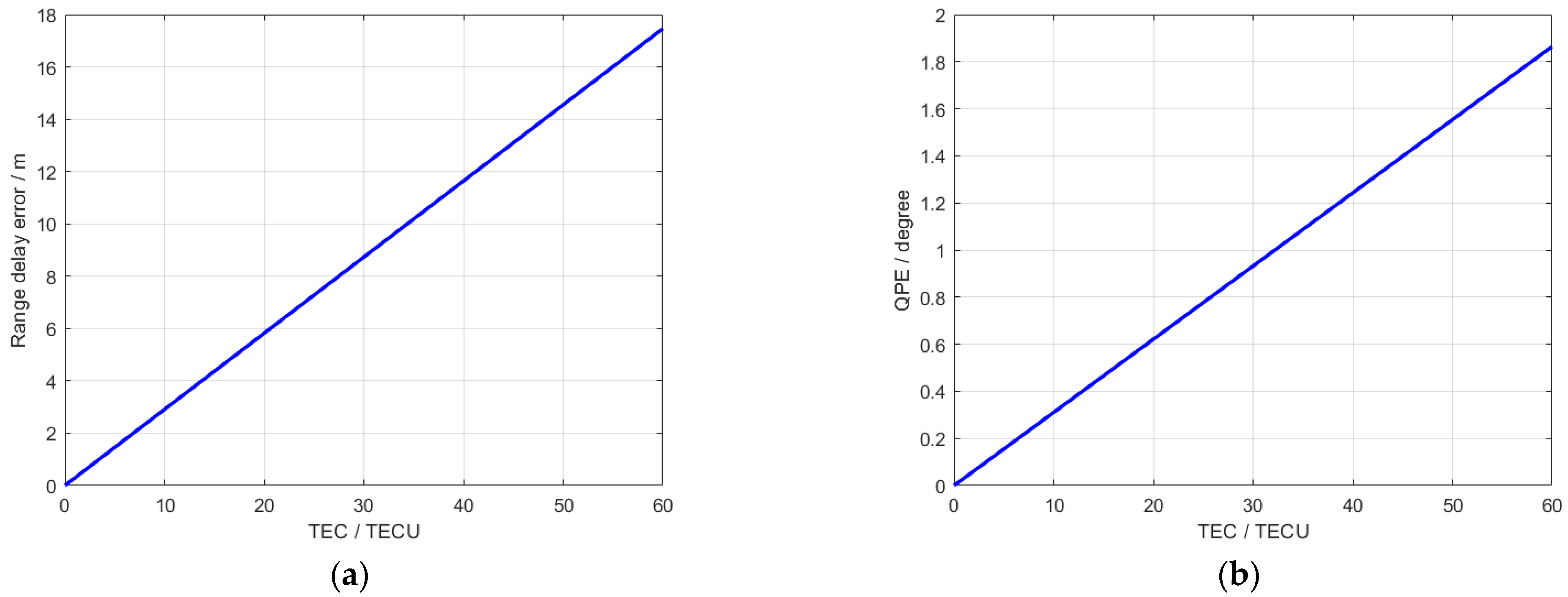
Equation (6) shows that the group delay and range delay error are proportional to the TEC in the ionosphere and inversely proportional to the f c 2 of the transmitted signal. Figure 5 takes the GPS L5 signal as an example to simulate the range delay and QPE introduced by ionospheric dispersion under different TEC. When the TEC is less than 50 TECU (the peak value of TEC throughout the day in the experimental area is less than 50 TECU), the range delay is less than one resolution unit. The QPE is less than 2 degrees. Therefore, it can be considered that ionospheric dispersion has no impact on the studied GNSS-BSAR imaging.
The ionospheric scintillation effect is caused by irregularities. The general method to describe the scintillation effect is to use the phase screen model, which treats the ionosphere as a thin layer (phase screen). As the satellite moves, the signal passing through the ionosphere sweeps across the ionospheric phase screen producing different additional phases. Due to the complexity of irregularities, the additional phase changes are random phases, and only statistical methods can be used to describe their characteristics. The power spectral density can be expressed as [28]:
P S D φ ( κ ) = T κ o 2 + κ 2 p
where κ o = 2 π / L o , L o represents the turbulence outer scale of irregularities. κ represents the wave number, p is the power spectrum index, and T represents a constant proportional to the ionospheric disturbance, expressed as:
T = A · C k L
where A represents a quantity that is related to parameters such as wavelength, radar viewing angle, and power spectral index, with the specific expression and value available from [28]. C k L represents the intensity of ionospheric disturbance at the 1 km scale.
Due to the phase error is random, only its statistical property can be analyzed. Using the power spectral density shown in Equation (7), the root mean square (RMS) of the phase error can be expressed as [28]:
ϕ R M S = 2 κ C P S D φ κ d κ
where κ C = 2 π / L C . L C represents the synthetic aperture length on the ionosphere. As the synthetic aperture time becomes longer, the azimuth resolution become finer, and the phase error introduced becomes larger.
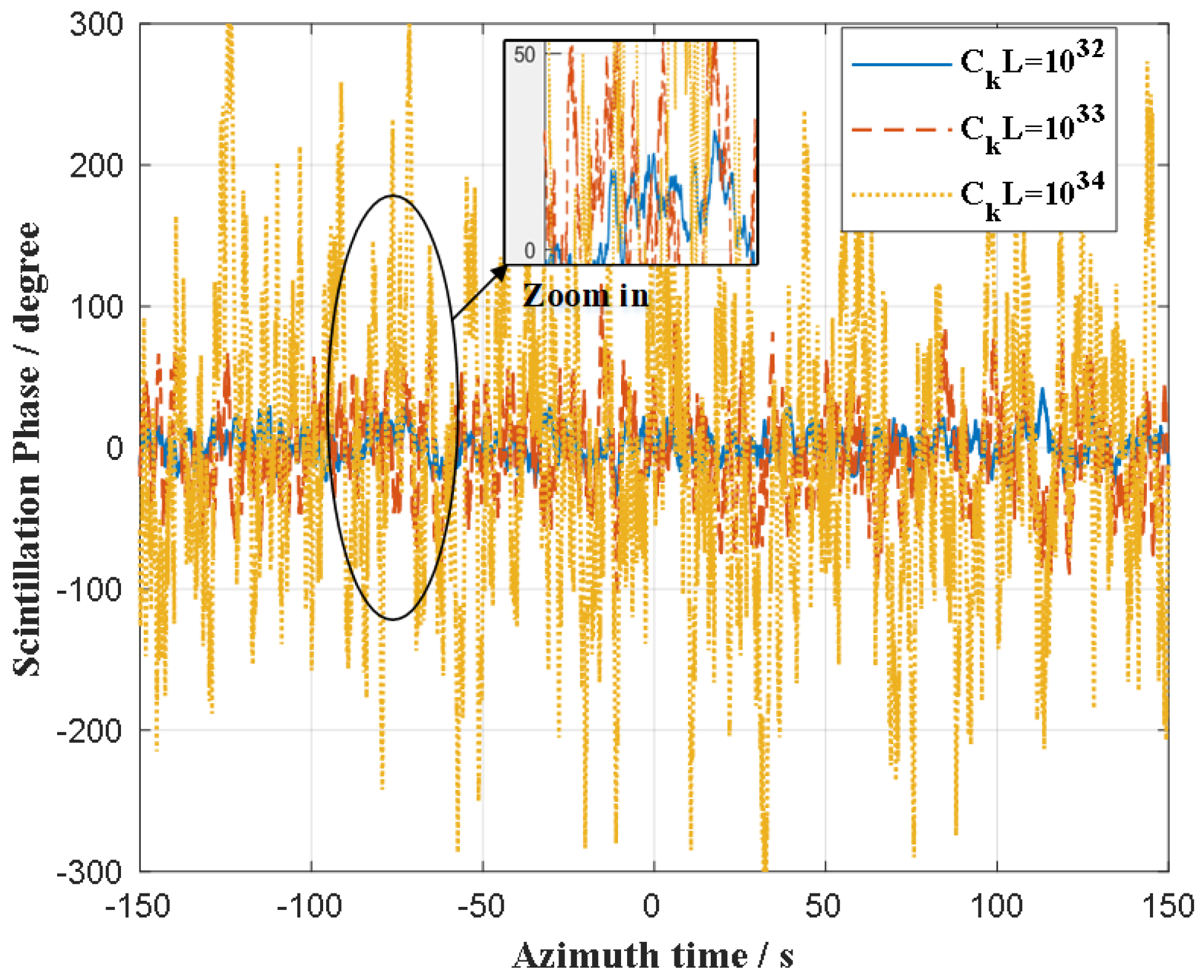
The scintillation effect will produce high-order phase errors in the azimuthal dimension. Figure 6 simulates the scintillation phase error of the GPS L5 signal under the ionospheric disturbance intensities C k L are 10 32 , 10 33 , and 10 34 , respectively, when it passes through the ionosphere. Moreover, 10 32 , 10 33 , and 10 34 represent weak scintillation, medium scintillation, and strong scintillation respectively. And the synthetic aperture time is 300 s. Figure 6 shows that even when the ionospheric scintillation is weak, the phase error caused by it can reach about 45 degrees. For GNSS-BSAR system, this phase error cannot be ignored and must be compensated to achieve precise azimuth focusing of SAR image.
The above analysis can be summarized as follows:
  • The atmosphere on the Earth’s surface is mainly divided into the troposphere and the ionosphere. In the studied GNSS-BSAR system, combining the signal and system characteristics, only the ionospheric effect is considered.
  • The ionospheric dispersion effect is caused by the background ionosphere, which causes delays and pulse width changes in the range dimension of the echo, resulting in range delay error. Due to the limitation of GNSS signal resolution, the impact of this error can be negligible.
  • The ionospheric scintillation effect will introduce random phase errors in the azimuth direction, thereby affecting the azimuth focusing and causing an overall increase in the side lobe level. The greater the intensity of the scintillation is, the worse the SAR image quality is. In next Section 3, the proposed ionospheric scintillation error extraction and compensation method based on the reference channel will be introduced in detail.

3. The Ionospheric Scintillation Compensation-Based Modified BP Imaging Method

The configuration of separate transmitter and receiver increases the flexibility and application, enabling the GNSS-BSAR system to provide richer spatial and geometric information in a variety of environments. However, the unique configuration also causes the target echo to have different characteristics from traditional monostatic SAR. The Back Projection (BP) algorithm can accurately process echo across different time and spatial locations and is suitable for bistatic SAR systems. This section first introduces the application of the traditional BP algorithm in the dual-channel receiving GNSS-BSAR system and analyzes the limitations of the current process. Then, the ionospheric scintillation phase error extraction technology based on reference channel processing is introduced, and error separation is performed through polynomial fitting. Finally, the modified BP algorithm is proposed, which divides the azimuth compensation phase of the imaging channel into difference phase and reference phase (including ionospheric scintillation error and other Doppler phase errors). This approach facilitates high-precision azimuth focusing in the GNSS-BSAR system through two-step azimuth phase compensation process.

3.1. Basic Process and Analysis of BP Imaging Algorithm

The BP algorithm is a classic imaging algorithm in time domain. It calculates the position and phase of echo at each grid point on the ground mesh falling on the signal mesh. The echo of that grid point on the ground mesh is coherently integrated. The echoes from other grid points are incoherently superimposed, resulting in a very low intensity. Therefore, the integrated intensity can reflect the electromagnetic scattering intensity at that grid point on the ground mesh. For the entire ground scene area, the above process is operated point by point, and finally, a well-focused SAR image can be obtained. The advantage of the BP algorithm is that the principle is clear. There are no restrictions on the motion mode of the radar platform, and no approximation is made during the derivation process. Therefore, the BP algorithm can be competent for various modes of SAR imaging processing. It is an imaging processing algorithm with high precision and wide applicability.
In the GNSS-BSAR system, the echo after pulse compression in the imaging channel can be expressed as:
S r 3 t , τ = rect τ R t / c T p P τ R t c exp j 2 π R t λ j 2 π f d c t
where P · represents the autocorrelation function of the ranging code. The meanings of other variables are the same as in Equation (5).
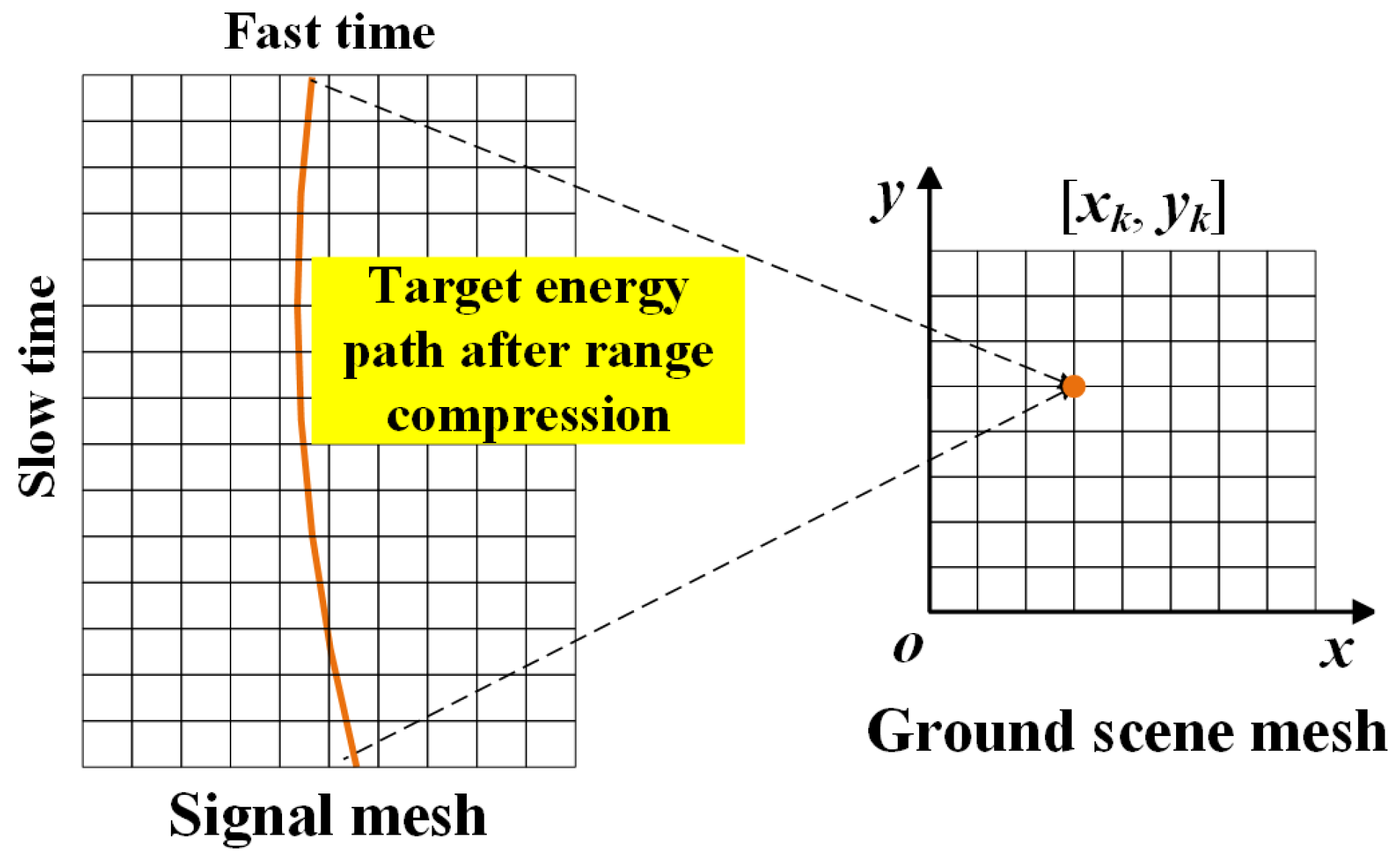
Figure 7 shows the process of data processing using classic BPA, which is described in detail below.
  • The imaging area is divided into a two-dimensional ground mesh, where x and y are the two-dimensional coordinates corresponding to the grid points respectively. And the ground grid spacing d x and d y should be smaller than the imaging resolution in the corresponding directions.
  • For a certain pixel point x k , y k on the ground mesh, the range migration trajectory τ = τ x k , y k ; t of the point is calculated according to its coordinate value and the positions of the GNSS transmitter and receiver. And then the energy of the target echo along the trajectory can be extracted. Finally, the azimuth-dimensional signal S r 3 t , τ x k , y k ; t can be recombined.
  • Based on the coordinate value x k , y k and the positions of the transmitter and receiver, Doppler phase history of the grid point can also be calculated. The azimuth phase compensation is operated on the one-dimensional signal S r 3 t , τ x k , y k ; t , that is, multiply it by the complex conjugate of the Doppler phase exp j 2 π R x k , y k ; t / λ j 2 π f d c t of the target echo at that point, eliminate its azimuth phase modulation.
  • Accumulate the one-dimensional signal S r 3 t , τ x k , y k ; t along the azimuth direction to obtain the coherent integrated energy of the target echo at that ground grid point and assign the integration result to S g x k , y k .
  • Traverse all points on the ground mesh and repeat the above steps 2–4 to obtain the final SAR image S g x , y projected onto the ground.
The whole process can be summarized as follows:
S g x k , y k = 0 N T p S r 3 t , τ x k , y k ; t × exp j 2 π R x k , y k ; t λ + j 2 π f d c t d t
After BPA processing, the focused SAR image backprojected onto the ground scene mesh can be obtained.
In the step 3 of the above processing flow, the Doppler phase history of the echo needs to be calculated and compensated based on the relative geometric relationship between the target, receiver, and GNSS satellite. In theory, there is no problem with this operation. However, for GNSS-BSAR imaging, the synthetic aperture time is usually long, especially for ground-based receiving configurations. To obtain fine azimuth resolution, it is often necessary to accumulate hundreds of seconds. GNSS satellites usually use atomic clocks, and the clocks are calibrated regularly, so they are relatively accurate. For radar applications, it is generally considered that the clock error of GNSS satellites can be ignored. In the GNSS-BSAR system, the impact of receiver clock error is mainly considered. The requirements for the frequency stability of the local oscillator of the receiver under ultra-long synthetic aperture time can be analyzed below. Taking a ground-based fixed receiver as an example, assuming that the synthetic aperture time T a of the system are 300 s and the azimuth phase accuracy requirement is Δ ϕ π , then the maximum frequency error allowed by the system is Δ f = Δ ϕ / 2 π T a 0.002 Hz . The requirements are quite strict and cannot be met by most conventional GNSS receivers. Therefore, the influence of the local oscillator drift of the receiver must be considered. In addition, according to the analysis in Section 2.3, the ionospheric scintillation effect will also introduce phase error.
In summary, under the long synthetic aperture time of GNSS-BSAR, the time-frequency errors and ionospheric scintillation error between the receiver and satellite transmitter will cause Doppler phase deviation, ultimately leading to azimuthal defocus. The modified phase compensation scheme for step 3 of current BP process is described in the following part.

3.2. The Proposed Modified BP Imaging Algorithm

3.2.1. Ionospheric Scintillation Error Extraction Based on Reference Channel Processing

In the GNSS-BSAR system, the direct wave signal received by the reference channel has the advantages of high SNR and simple equivalent range model. The dual-channel receiving system uses the same local oscillator, which provides coherence. In the studied scenario, the target scene area was close to the receiver, and it could be considered that the two channels had the same Doppler phase error. Here, the reference channel signal was first analyzed, and the overall Doppler phase error was extracted for imaging channel phase compensation. In addition, the ionospheric scintillation error is separated from the overall errors to provide possible reference information for ionospheric research.
In actual data processing, the reference channel directly receives the navigation satellite signals through the right-hand circularly polarized antenna. The signal processing flow is shown in Figure 8. First, it was necessary to capture the navigation signal and determine the currently visible satellites. Then, the accurate initial code phase and carrier frequency were obtained through tracking, which was used for bistatic synchronization and Doppler phase (or carrier) extraction. Finally, through navigation data decode and position computation, the position coordinate of the navigation satellite with the receiver as the coordinate origin was obtained, which was used for subsequent SAR imaging. The principle of navigation signal acquisition and tracking is very mature [29] and will not be described in detail in this paper. Taking the intermediate frequency receiver as an example (the experimental data in this work are also collected through IF receiver), the tracked carrier frequency contains the Doppler frequency/phase information for every millisecond of the radar observation duration. The tracked carrier frequency is very important for azimuth focus of the signals in imaging channel.
The tracked carrier frequency is recorded as T f d t , t represents the azimuth time (also called slow time), and the interval is 1 ms. A carrier frequency update value can be tracked and obtained after each equivalent pulse. It is worth noting that this paper uses an IF receiver as an example, and the tracked carrier frequency has not undergone IF demodulation. Because T f d t is discrete, the measured Doppler phase of the reference channel can be obtained by accumulation as follows:
ϕ r e f t = i = 1 N t T f d t i I F c × T p
where I F c represents the tracked carrier frequency at the radar observation center time. T p represents the equivalent pulse repetition period, which is 1 ms. i represents the azimuth time corresponding to the i-th pulse. In the above equation, N t changes with the independent variable t, corresponding to the number of pulses when the independent variable takes a certain value.
In actual measurements, the reference phase ϕ r e f is not only the Doppler phase generated by the movement of the navigation satellite relative to the receiver, but also includes the frequency error of the receiver’s local oscillator and the influence of ionospheric scintillation effects. Therefore, the reference phase can also be expressed by the following form:
ϕ r e f t = 2 π R x r , y r ; t λ 2 π f d c t + ϕ e ϕ e = ϕ l e + ϕ h e
where f d c represents the satellite Doppler central frequency. x r , y r represents the coordinates of the receiver. ϕ l e represents the low-order phase error from zero to third order, which is caused by the fixed frequency offset of the receiver intermediate frequency and the drift of the local oscillator of the receiver. ϕ h e represents the residual high-order phase, which is the phase error caused by atmospheric effects and thermal noise. According to the analysis in Section 2.3, the high-order phase error is mainly the phase error caused by ionospheric scintillation. Using polynomial fitting, the ionospheric scintillation error can be extracted from the reference phase as information for analyzing the impact of atmospheric effects. The process can be expressed as follows:
ϕ i o n t = ϕ h e t = ϕ r e f t ϕ l e t = ϕ r e f t i = 0 3 w i t i
where w i represents the i-th order polynomial fitting coefficient.
It is worth mentioning that in the proposed modified BP algorithm, the extracted reference channel Doppler phase will be used as a whole for phase compensation. But for the purpose of analyzing the impact of ionospheric scintillation error and observe the possible diurnal variation curve of ionospheric scintillation, the ionospheric scintillation error will be stripped off using Equation (14) in this paper. In the actual experimental data processing, the imaging results before and after ionospheric scintillation error compensation will be separately studied.

3.2.2. The Two-Step Azimuth Phase Compensation-Based Modified BP Imaging Algorithm

Utilizing the characteristics of dual-channel receiving of the GNSS-BSAR system, this paper proposes a two-step azimuth phase compensation algorithm to solve the problem of errors compensation, such as ionospheric scintillation phase error under ultra-long synthetic aperture time. This method decomposes the azimuth phase of the target echo into the reference phase extracted from the reference channel and the difference phase of the target point relative to the direct wave signal of the reference channel. For the ground-based fixed receiver platform, the imaging area is close to the receiver, and the reference channel and imaging channel use the same local oscillator. And Figure 4 also shows that the ionospheric effect has almost the same impact on R d and R t (blue dashed line and red solid line). Therefore, the phase errors of the signals of the two channels can be considered consistent. The azimuth doppler phase extracted from the reference channel signal not only includes the Doppler phase caused by the motion of the satellite transmitter relative to the receiver, but also includes the error caused by the local oscillator drift of the receiver, the receiver thermal noise error, and the ionospheric scintillation error.
Taking the receiver as the coordinate origin, the ENU coordinate was established as Figure 4. For the target point k located at x k , y k , its azimuth phase can be expressed as:
ϕ k t = 2 π R x k , y k ; t λ 2 π f d c t + ϕ e
where ϕ e represents the sum of various azimuth phase errors after removing the satellite motion’s Doppler phase. Based on the analysis in Section 3.2.1, the phase error ϕ e was approximately consistent in the reference channel and imaging channel.
According to the analysis in Section 3.2.1, the azimuth reference phase of the reference channel signal can be expressed as the Equation (13). Because the ENU coordinate system uses the receiver as the origin, x r , y r = 0 , 0 in the Equation (13). According to the previous analysis, ϕ e cannot be calculated accurately, but it can be estimated and eliminated using the Doppler phase tracked by the reference channel.
By deforming the expression of the azimuth phase in Equation (15) of the target point k, we can obtain:
ϕ k t = 2 π R x k , y k ; t λ 2 π f d c t + ϕ e = 2 π R x r , y r ; t λ 2 π f d c t + ϕ e + 2 π R x r , y r ; t R x k , y k ; t λ = ϕ r e f t + ϕ d i f f x k , y k ; t
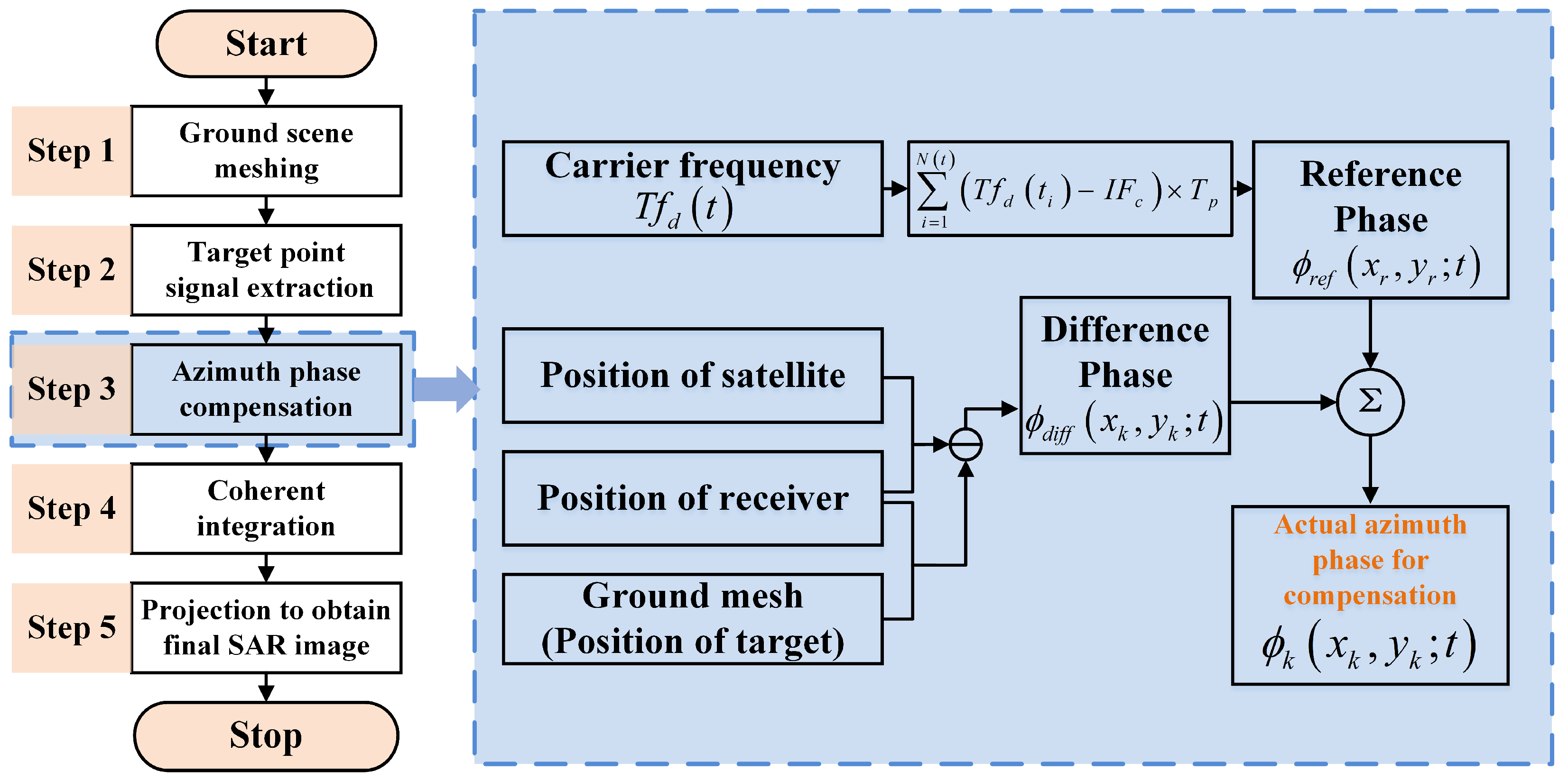
where we define ϕ d i f f x k , y k ; t = 2 π R x r , y r ; t R x k , y k ; t / λ as the difference phase. In this way, the azimuth phase of the target point k is decomposed into two parts: the reference phase and the difference phase, which facilitates phase compensation in actual data processing.
The flow chart of the two-step phase compensation algorithm is shown in Figure 9. First, the Doppler phase extraction technology was used to extract the carrier frequency observations tracked by the reference channel and obtain the reference phase ϕ r e f t through integration. Then, the satellite position information obtained from ephemeris calculation and the receiver position information obtained from positioning were used to calculate the difference Doppler phase ϕ d i f f x k , y k ; t between target point k and the receiver. Finally, the two types of phases were added to give the actual azimuth phase ϕ k t required for compensation. Use the resulting ϕ k t to replace the target Doppler phase in step 3 in Section 3.1. Then, continue to complete steps 4 and 5 to obtain a SAR image with high-precision focus in azimuth.

4. Experimental Results

To verify the feasibility of the proposed modified BP algorithm and explore the influence of ionospheric effects on the GNSS-BSAR system, we developed a GNSS-based passive radar experimental platform. Experiments were conducted at three distinct times—morning, midday, and evening—on a specific day to perform SAR imaging for the same scene, as detailed below.

4.1. Experimental Setup

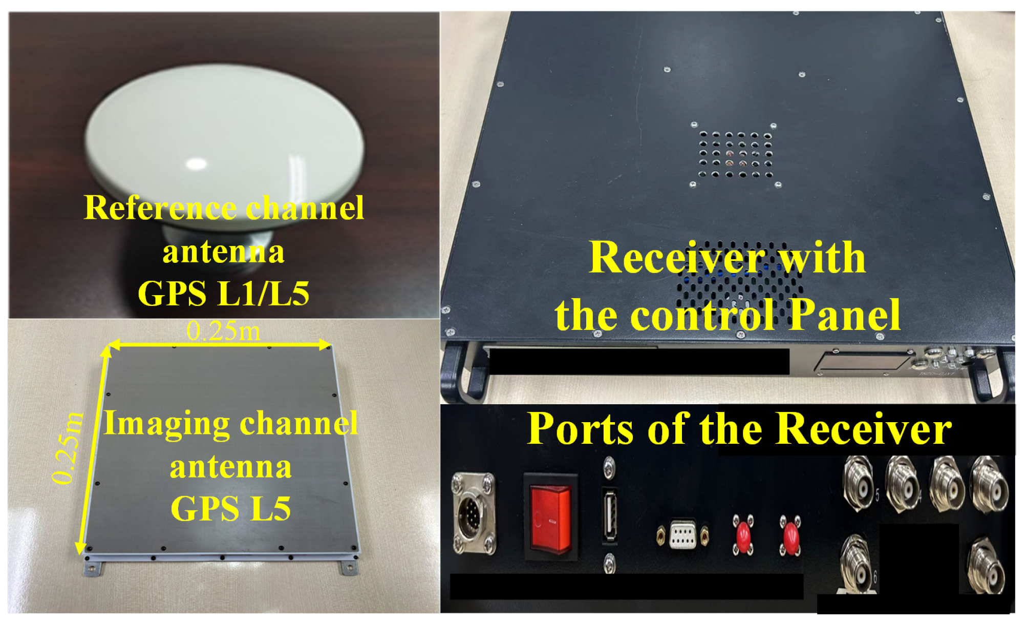
The constructed experimental platform is shown in Figure 10. It included a GNSS signal high-speed acquisition receiver, which adopted a superheterodyne structure design and directly stores the original intermediate frequency signal to facilitate subsequent flexible data analysis and processing. It also included L5 high-gain reflected signal receiving antenna, full-frequency GNSS direct signal receiving antenna, and supporting power supplies, cables, mobile workstations, etc. Considering that GNSS signals are right-hand circularly polarized electromagnetic waves, the platform used the left-hand circularly polarized antenna to receive echo to maximize the reflected energy and suppresses the direct signal energy.
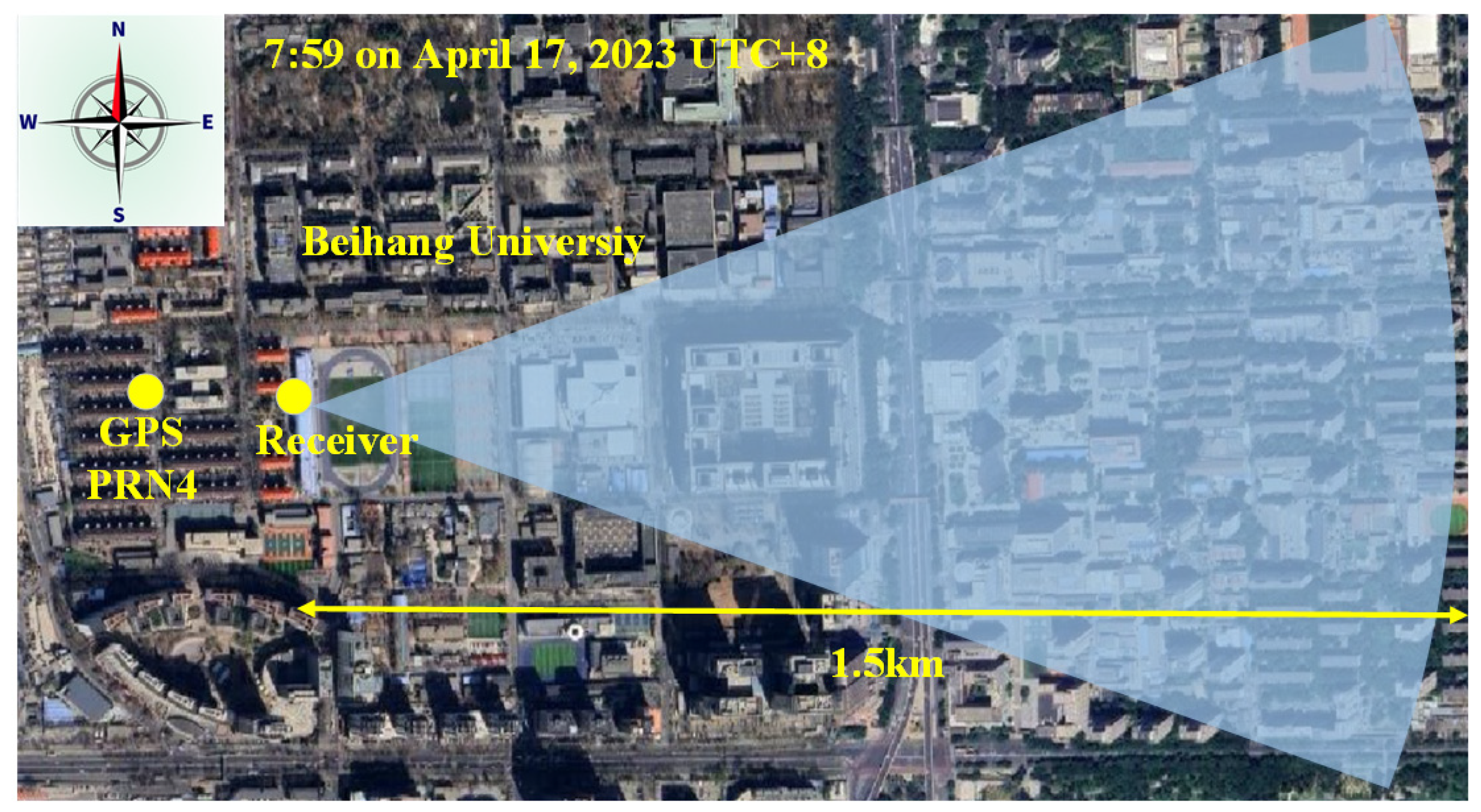
The GNSS-BSAR imaging experiment was carried out at the Xueyuan Road Campus of Beihang University in Beijing, China. The experiment collected data at three different times in the morning, middle and evening of a certain day, namely 7:59 on 17 April 2023, 11:55 on 17 April 2023, and 23:04 on 17 April 2023 (UTC + 8). It is worth mentioning that the weather on the experiment day was clear. However, the intensity of ionospheric scintillation is influenced by many complex factors, including solar activity, geomagnetic activity, geographic location, and seasonal variations. The recorded data and the proposed processing method in this paper only provide a preliminary validation of the diurnal variation of ionospheric scintillation, conducting a qualitative study. Therefore, the atmospheric and weather conditions at the moment of obtaining the three sets of experimental data are not described in detail here. The on-site photos of the experiment are shown in Figure 11. Taking the first set of experiment as an example, the illustration of the experimental scene is shown in Figure 12. For ease of system setup, the left-hand circularly polarized receiving antenna was placed at a height within 1 m above the ground. Additionally, considering the obstructions in the surrounding environment and the polarization characteristics of the reflected navigation signals, we set the cutoff elevation angle for GPS satellites at 30 degrees. The receiver was placed on the playground stand, and the reflect antenna pointed east to observe nearby buildings within about 1.5 km. The GPS satellite PRN4 was selected as the illuminator, which formed a typical backscattering configuration with the receiver and imaging area. Each set of experiments carried out 5 min of continuous observation. Table 1 lists more experimental parameters. When using GNSS signals for positioning, multipath interference elimination is often considered. In this paper, we used the GNSS signals for bistatic SAR imaging, and the influence of multipath effects is not considered in this application. After long-time coherent processing, multipath effects may be reflected in the final SAR imaging product. This requires subsequent potential image interpretation and analysis, which is beyond the scope of this paper.

4.2. Reference Channel Processing Results

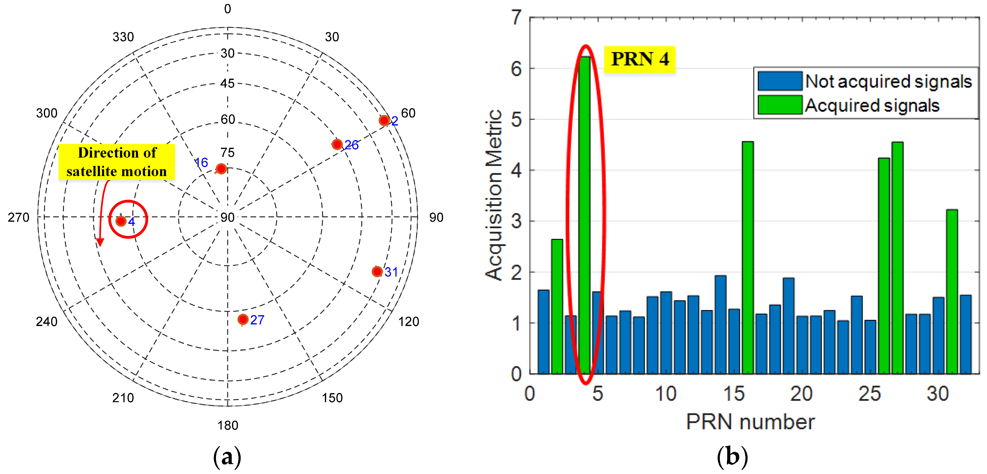
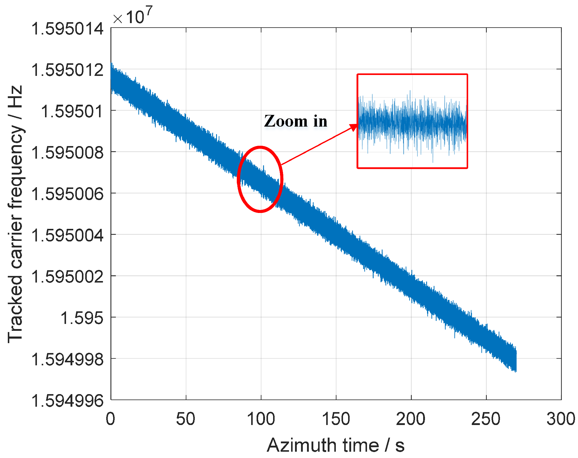
The reference channel data were processed using the proposed method in Section 3.2. Taking the first set of experimental data (7:59 on 17 April 2023) as an example, Figure 13 shows the results of GPS satellite acquisition and tracking. More than four GPS satellites were successfully captured. In order to make the transmitter and receiver located on the same side of the imaging observation scene, forming a typical bistatic configuration, the GPS satellite PRN4 was selected as the transmitter. Figure 14 shows the precise carrier frequency obtained by continuous tracking for 300 s for this satellite. After partial amplification, it can be clearly seen that the measured carrier frequency (Doppler) had been experiencing severe jitter. The tracked carrier frequency could be used to calculate the Doppler phase, which still contained intermediate frequency information of the receiver.
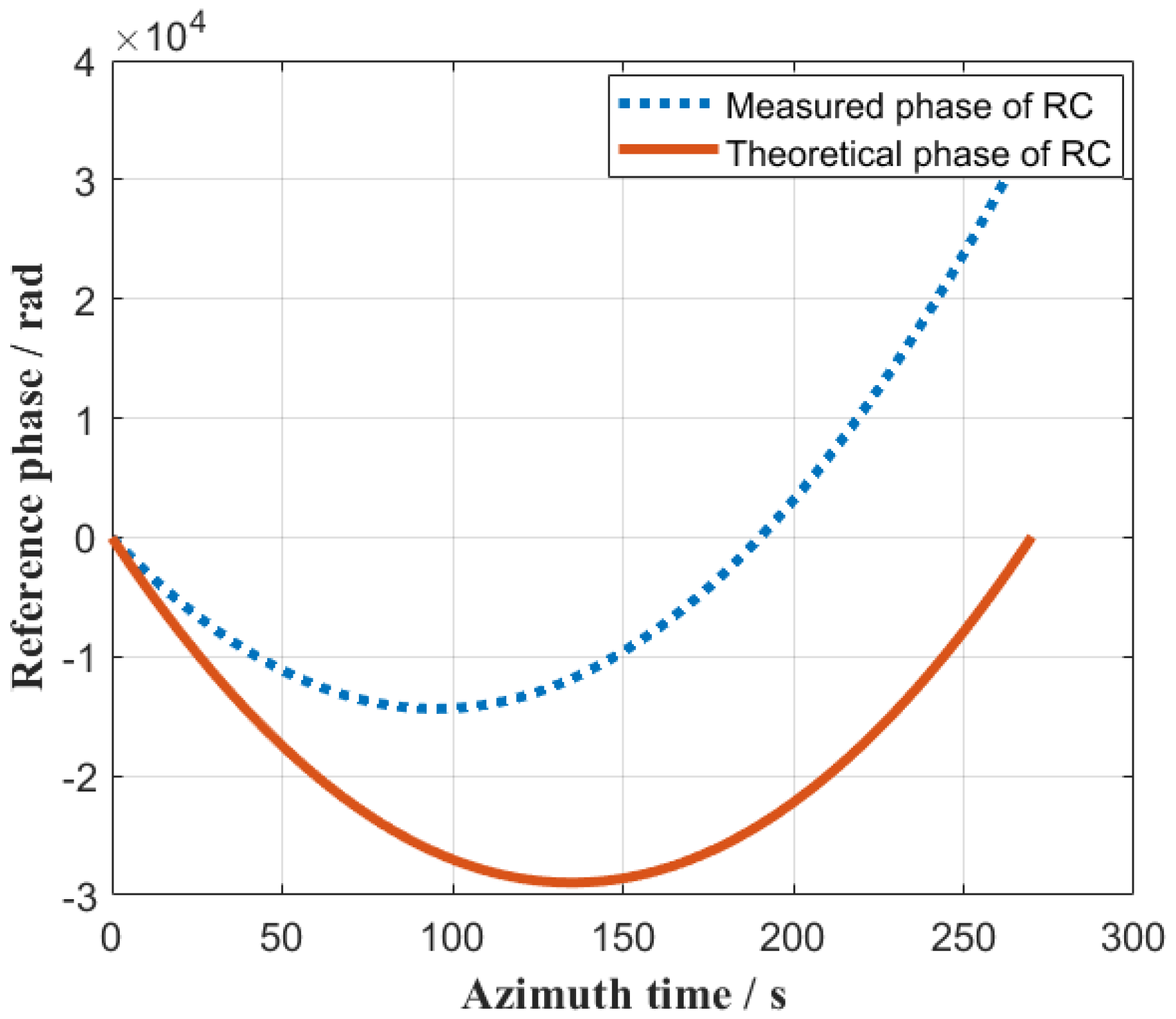
According to Equations (12) and (13), the measured value and theoretical value of the Doppler phase of the reference channel could be calculated, and the results are shown in Figure 15. There was a clear difference in Doppler center frequency. Moreover, since the measured Doppler phase was obtained by the tracked carrier frequency (as shown in Figure 14), it was not as smooth as the theoretical Doppler phase and has fluctuations. Due to the long synthetic aperture time, if the theoretical phase curve is directly used to achieve phase compensate for the echo, the energy of the target between different pulses will be directed at different phase angles, or even cancel each other, making effective energy integration impossible.
Furthermore, using the proposed error extraction method in Section 3.2, the ionospheric scintillation error could be extracted from the measured Doppler phase. Figure 16 shows the total Doppler phase error and the fitted ionospheric scintillation error extracted from the three sets of data in the morning, midday, and evening. The three experiments used GPS satellite PRN 4, 30, and 18 as transmitters, respectively. The sky map at that moment of the experiment can be found on the public website, which is consistent with the results obtained by acquisition and tracking. The trends of the total Doppler phase errors obtained from the three experiments were generally consistent. This was because the azimuth angles and trajectories of the three satellites were relatively close at that time of observation. Polynomial fitting was performed on the total phase error, and the residual value after fitting mainly reflected the influence of the ionospheric scintillation error. Regarding these three data sets, the ionospheric scintillation phase during the morning and noon remained within two radians, while it increased at night, reaching up to five radians. It can be preliminarily verified that there were changes in ionospheric scintillation at different times of the day. In addition, the specific curve that can reflect the diurnal variation of ionospheric scintillation requires more experimental data for statistical analysis to be obtained.

4.3. Imaging Channel Processing Results

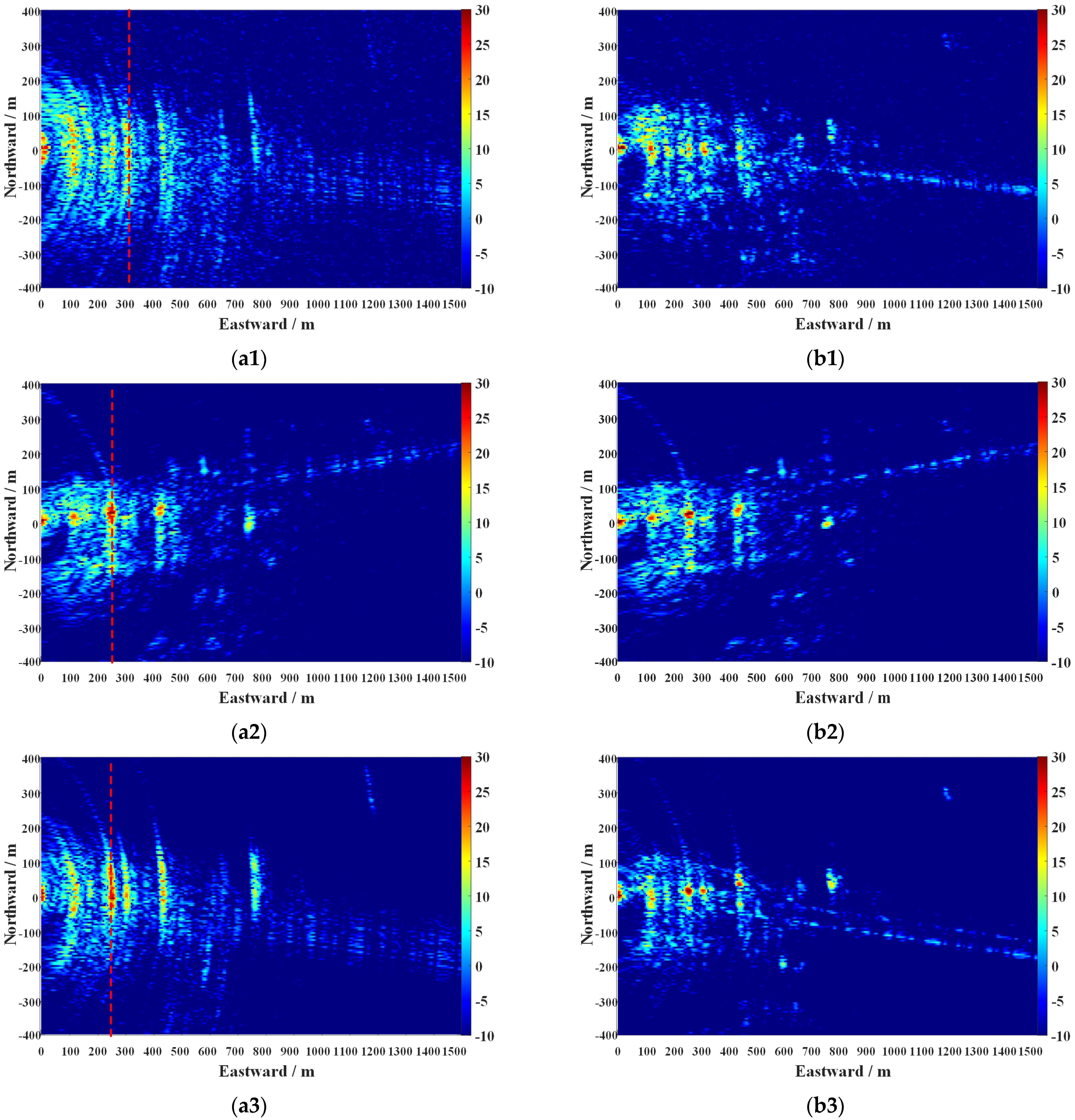
The proposed modified BP algorithm was used to perform two-step azimuth phase compensation on the three sets of experimental data using the Doppler phase extracted from the reference channel. The echo energy of the target between different pulses was adjusted to be consistent, and coherent integration could be achieved. Figure 17 shows the imaging results before and after ionospheric scintillation error compensation. The red dotted lines indicate the location of the selected strong scattering areas, which were used for subsequent comparative analysis of the azimuth profile. Here, we performed error separation on the total Doppler phase, and we only compensated or did not compensate the residual error after polynomial fitting to separately observe the impact of ionospheric scintillation. In fact, azimuth focusing can be achieved by directly using the total reference channel Doppler phase for compensation according to the process in Figure 9.
To reduce the contrast ratio of the imaging results, the SAR images were taken as decibel values and normalized with the noise energy as the reference. Without ionospheric scintillation error compensation, the imaging results were obviously defocused in the azimuth direction. In addition, when different satellites (PRN4, 30 and 18) were used as illuminators, the strong scattering areas of the imaging results were roughly the same, but there were still differences. For example, the amplitude at the position 300 m eastward in Figure 17(b1) was significantly stronger than Figure 17(b2). This was because there were certain differences in the altitude angles of the three satellites at the experiment time, and the geometric configurations could not be exactly the same, which ultimately led to differences in strong scattering details.

5. Discussion

5.1. Performance Analysis of the Proposed Method

5.1.1. Comparative Analysis with Phase Gradient Autofocus (PGA)

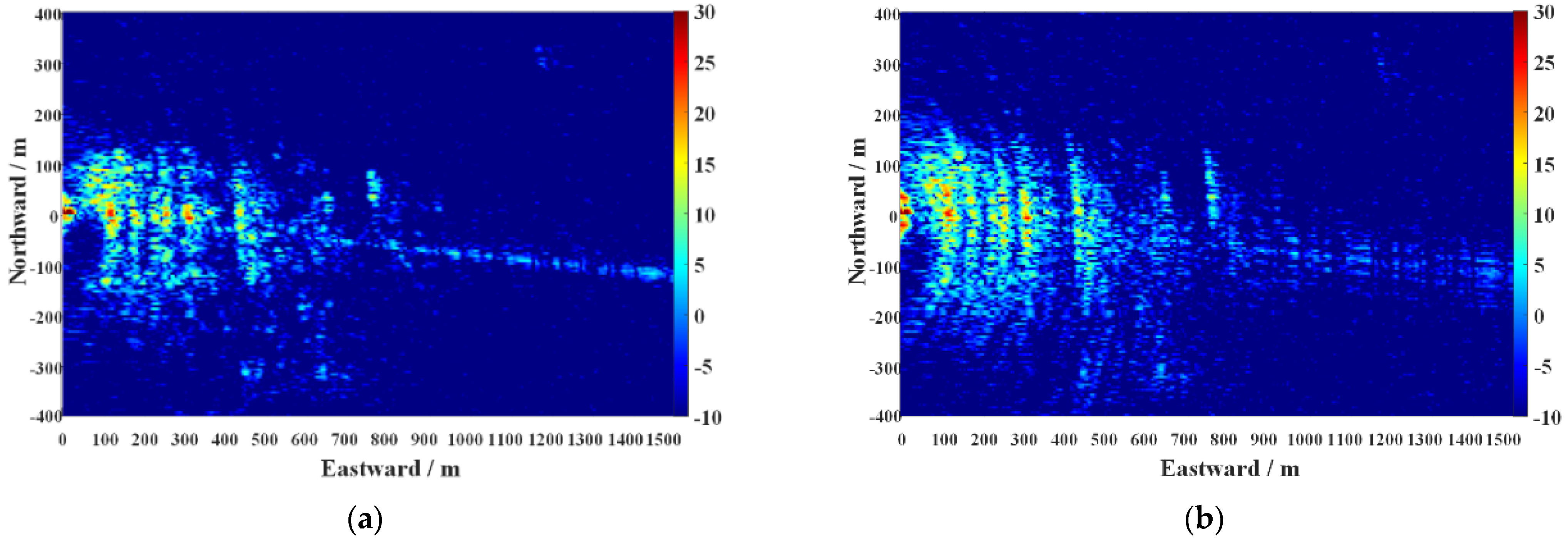
Autofocus algorithms are effective techniques for addressing phase errors in SAR signals. These algorithms estimate the phase error function from the echo data and then compensate for it to obtain well-focused images. The PGA algorithm, based on the maximum likelihood estimation theory, provides optimal estimation and is suitable for high-resolution SAR phase error correction in most imaging scenarios. In this section, both the proposed method and the traditional PGA algorithm were used to process the degraded imaging results of the first set of experimental data (7:59 on 17 April 2023, UTC + 8). The comparative processing results are shown in Figure 18.
Compared to the original imaging result without azimuth phase error compensation, Figure 18 show significant improvements in the azimuth focusing. However, it can be observed that the improvement in the imaging result after PGA processing was relatively limited. This is because the PGA algorithm has certain limitations, particularly its dependence on prominent points in the scene. Due to the limited range resolution of the studied GNSS-BSAR system, it is difficult to have isolated strong points within the same range resolution cell. Additionally, the PGA algorithm has limited capability in estimating and compensating for low-frequency and high-order phase errors. For cases with significant defocusing, as shown in Figure 17(a1), the performance of PGA is not ideal.
On the other hand, the processing result of the proposed method, as shown in Figure 18b, exhibited better focusing performance. The comparison of the azimuth profile before and after processing will be introduced in the Section 5.2. This is because the proposed method directly utilizes the reference phase extracted from the reference channel for compensation, without relying on the limitations of scene contrast or parameter estimation capabilities, and does not require the presence of strong prominent points in the scene. When the analysis in Section 3.2.1 is satisfied, it can be considered that the reference channel and the imaging channel experience the same phase errors. Using the proposed two-step phase compensation algorithm, high-precision azimuth focusing can be achieved. From this perspective, the proposed method is not a new method in mechanism, but rather a novel method in the processing mode specifically designed for the dual-channel GNSS-BSAR system. The results of the actual data processing also demonstrate its effectiveness in addressing the azimuth degraded problem in GNSS-BSAR imaging.

5.1.2. Computational Complexity Analysis

One complex multiplication was considered equivalent to six floating-point operations (FLOPs), and one complex addition was two FLOPs. The interpolation kernel length is N i n , and one interpolation operation requires 2 2 N i n 1 FLOPs. Based on the processing flow in Section 3, the computational complexity of the proposed two-step azimuth phase compensation-based BP method could be calculated.
I p r o p o s e d = N x N y N a 4 N i n 2 N a + 8
where Na represents the equivalent number of pulses in the azimuthal dimension. The directions of x and y are consistent with the definitions in Figure 7. Nx and Ny represent the number of ground grid points in the corresponding directions. It can be observed that the computational load of this algorithm is mainly influenced by the size of the ground scene grid. Additionally, the above computational load is calculated starting from the signal in Equation (10), excluding the computational load of navigation signal preprocessing and range pulse compression.
In the data processing of this work, the algorithm’s parameters are set in Table 2.
dx and dy represent the grid resolutions in the corresponding directions, both set to 5 m. Given the imaging scene of 1500 m by 800 m, the values for Nx and Ny could be determined. The calculated computational load for performing imaging operation was approximately 1.04 TFLOPs. The program was executed in MATLAB R2022b on a computer equipped with an Intel Core i7-10750H @ 2.60 GHz processor and 64 GB RAM. The proposed method’s execution time was about 6241 s. It is worth noting that when combining the ionospheric scintillation error compensation (whether the proposed two-step processing method or the traditional PGA-based method) with the BP algorithm, the time consumed by BP imaging far exceeds that of the former. In other words, the computational load of the former can be almost ignored. Therefore, the computational complexity focuses solely on the deployed method in this paper, without comparing it to other possible algorithms.

5.2. Imaging Performance Evaluation

Figure 19 displays the azimuth profiles of strong scattering areas from three imaging sets, located at 340 m east, 270 m east, and 270 m east, respectively, corresponding to the position of the red dotted line in Figure 17(a1–a3). The blue dashed line in the figure represents the azimuth profile before ionospheric scintillation error compensation, showing significant defocusing and low peak energy. In contrast, the solid red line is the compensated azimuth profile, which is clearly well-focused. To enhance the clarity of the curves in the north direction, the receiver was used as the origin of the coordinates, and only a range of 400 m was intercepted. The actual imaging range extended 800 m in the northward (as indicated in Figure 17). The effectiveness of the proposed modified BP method based on two-step phase compensation has been preliminarily verified.
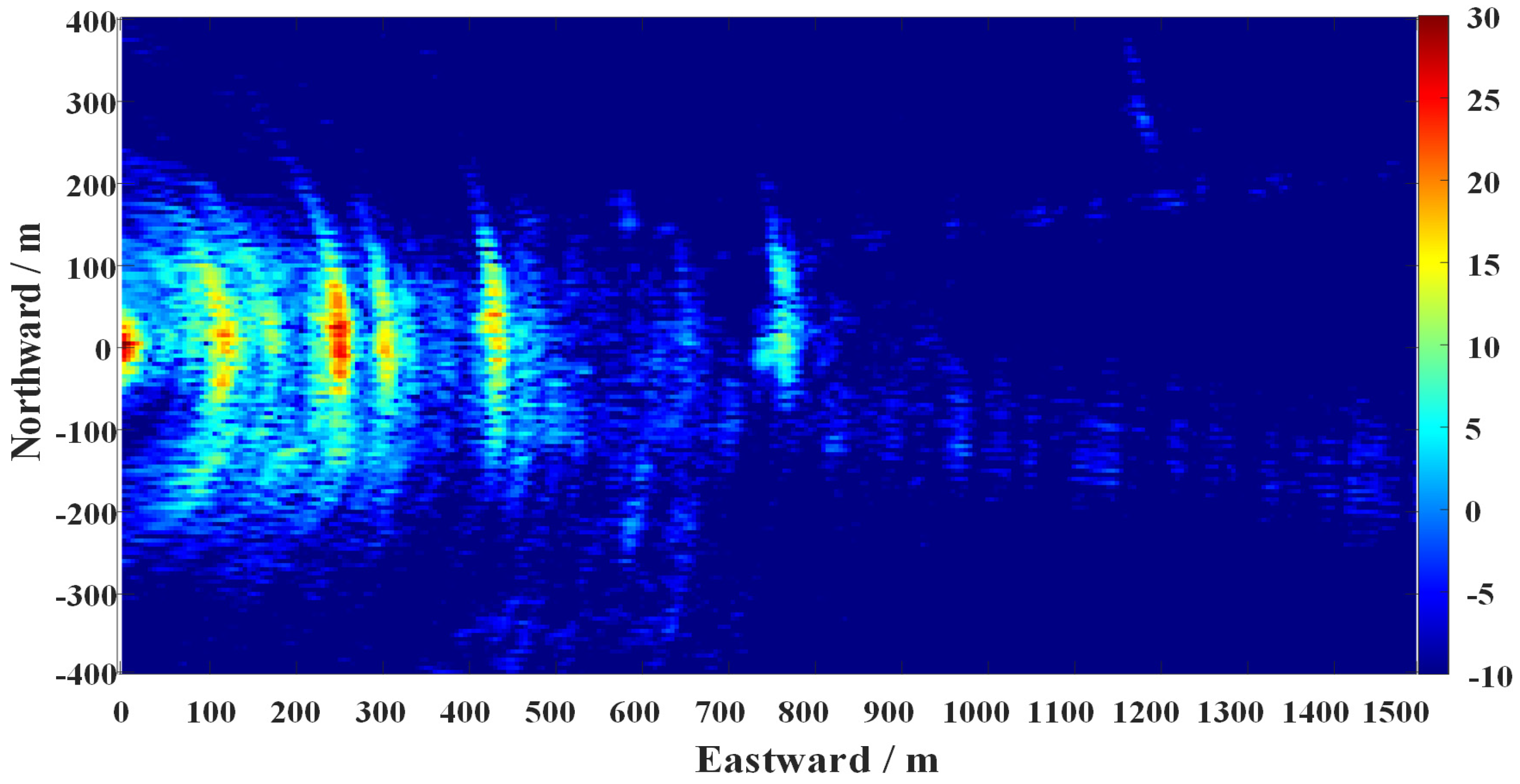
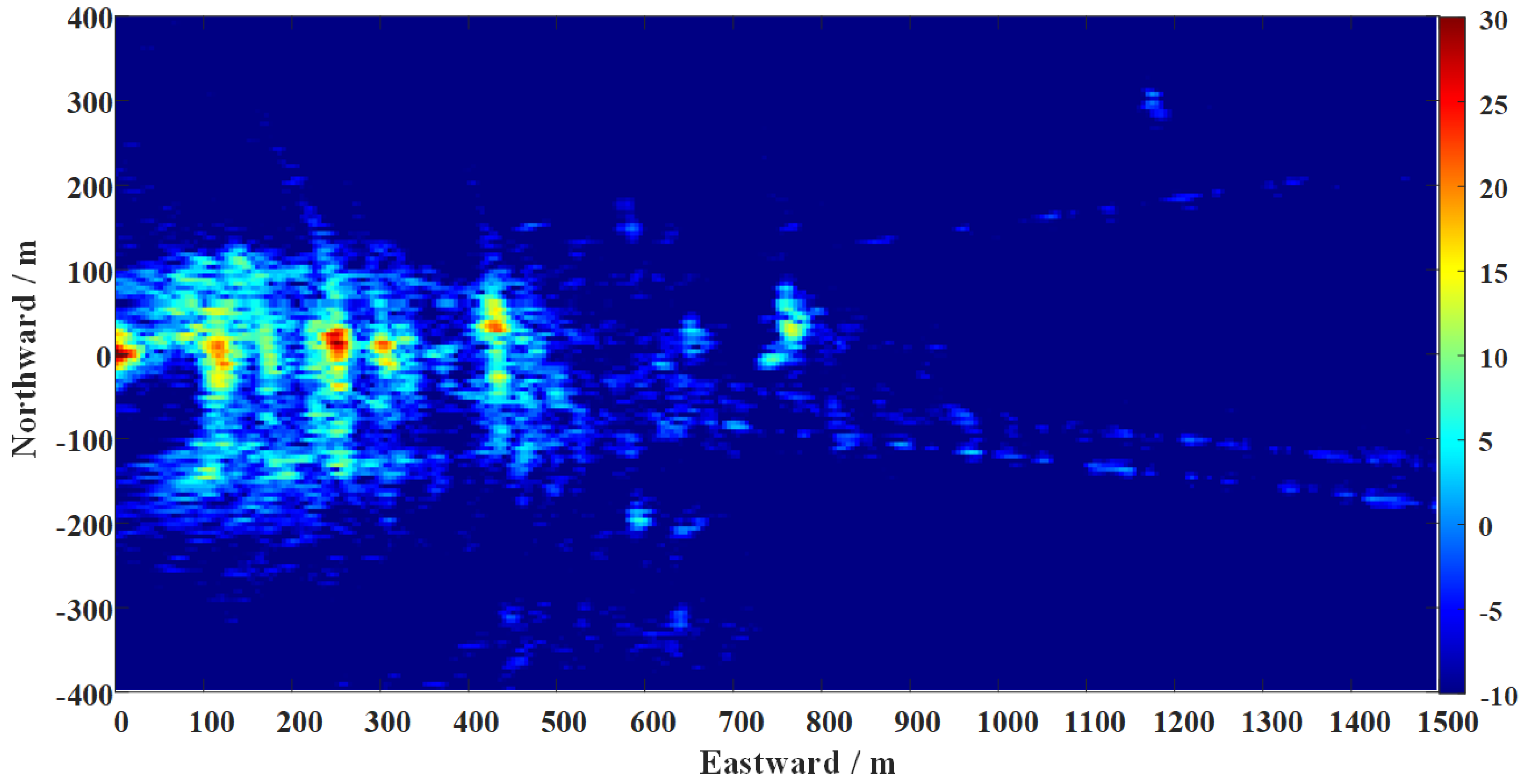
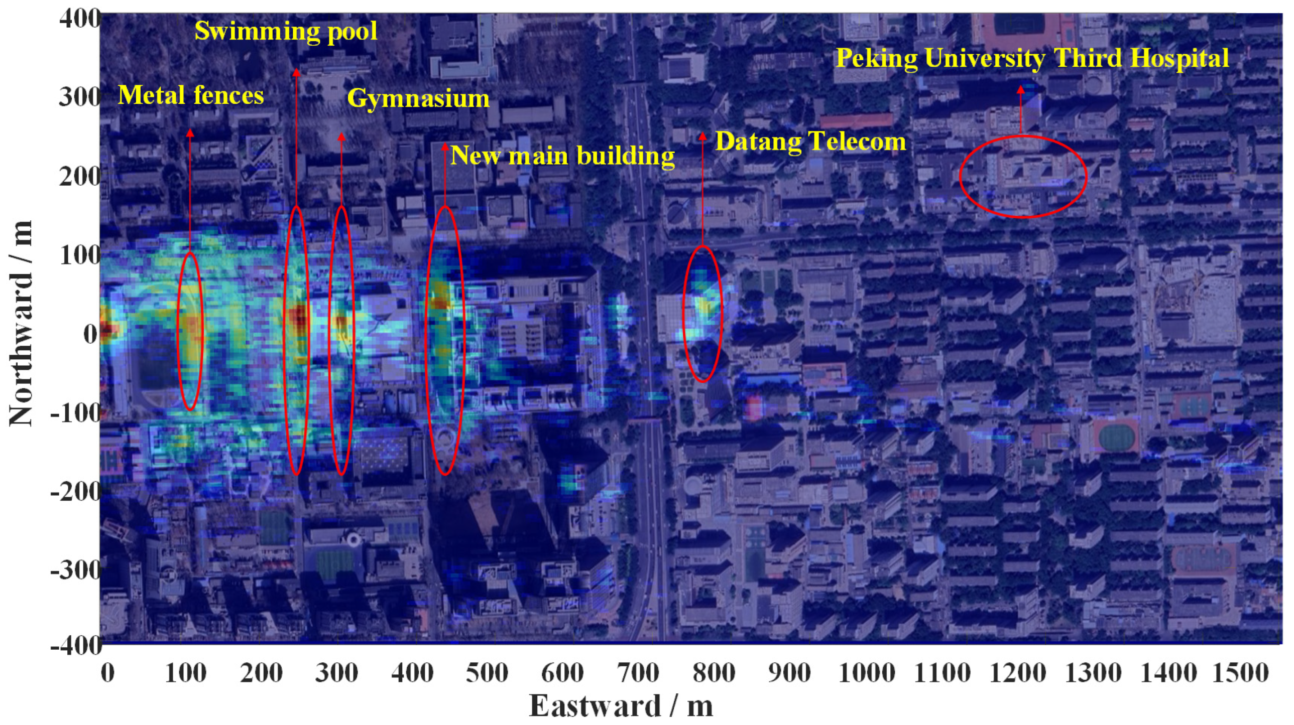
According to the analysis in Section 4.3, the three groups of experiments had different strong scattering points because of using different transmitters (GPS satellites). Through incoherent superposition, the fusion results of the three experimental data sets can be obtained. Figure 20 and Figure 21 display the results before and after compensation for ionospheric scintillation errors, respectively. Overlaying Figure 21 with the optical image of the area (from Google Earth), the effect is shown in Figure 22. Clearly, the strong scattering area of the SAR image roughly coincided with the target position of the optical image. Some strong scattering areas included the swimming pool about 270 m to the east, the gymnasium about 340 m to the east, the front edge of the new main building about 470 m to the east, the office building of Datang Telecom about 780 m to the east, Peking University Third Hospital about 1270 m to the east, etc. In addition, the metal fences of playgrounds and basketball courts formed a dihedral angle with the ground (about 100 m and 185 m eastward) at those experimental moments, which also caused strong electromagnetic scattering.

5.3. Limitaitons and Future Work

There are still limitations to the current work. On the one hand, it relies on only three sets of experimental data to extract ionospheric scintillation errors and perform SAR imaging. However, the ionospheric scintillation is related to local time, season, solar activity cycle, geomagnetic activity, and other factors. The study of its mechanism is a very complex research subject, which is beyond the scope of this paper. Based on the characteristics of dual-channel receiving, this paper focused on the compensation of the Doppler phase error introduced by ionospheric scintillation in the GNSS-BSAR system. Therefore, more experiments and mathematical statistical analysis need to be carried out in the future, which may provide helpful references for the study of ionospheric effects. On the other hand, the employed BP algorithm has high computational complexity. Speeding up the data processing efficiency for large-scale imaging is also an issue that will continue to be studied in the future. Finally, it is worth mentioning that Figure 20 demonstrates the use of the incoherent accumulation method for preliminary image fusion. The results illustrate the natural potential of GNSS-BSAR in multi-source fusion, which is also our possible future research direction.

6. Conclusions

This paper explored GNSS-BSAR imaging, focusing on the extraction and compensation of phase errors due to atmospheric effects and receiver’s time-frequency errors under long synthetic aperture time. Based on the dual-channel receiving characteristic of the system, a modified BP imaging algorithm using two-step azimuth phase compensation was proposed. Initially, the reference phase was extracted from the received direct wave of the reference channel, extracting both low-order phase errors from receiver local oscillator drift and high-order phase errors due to ionospheric scintillation. Subsequently, the target echo’s azimuth phase in the imaging channel was divided into reference phase and difference phase. The former can be corrected using the Doppler phase extracted from the reference channel, while the latter can be solved based on the positional information. This algorithm can eliminate the azimuth phase error in the imaging channel and effectively improve the focusing accuracy of SAR images. Experiments using GPS L5 signals as illuminators were conducted at different times in the morning, midday, and evening, performing coherent accumulation imaging about 300 s on a 1.5 km by 0.8 km ground scene. The comparative processing results with PGA show that the proposed method was not limited by scene contrast, prominent scatters, high-order error estimation capability, or iterative convergence. It can directly compensate for azimuth phase errors, demonstrating more precise azimuth focusing capability, which verifies the effectiveness and advantages of the proposed method in the studied dual-channel GNSS-BSAR system. Moreover, ionospheric scintillation errors extracted from these experiments indicate diurnal variations in ionospheric scintillation intensity, suggesting potential research applications.
The proposed method can also be adapted to other passive SAR imaging systems, offering certain applicability. Future work will aim to enhance the algorithm’s processing efficiency. In addition, the intensity of ionospheric scintillation is related to factors such as solar activity, geomagnetic activity, geographic location, and seasonal variations. Therefore, more experiments and analysis will be designed, which may provide helpful references for enriching the ionospheric research.

Author Contributions

Conceptualization, T.T. and J.C.; data curation, Z.R. and P.Z.; formal analysis, T.T. and H.Y.; investigation, Z.R.; methodology, T.T. and P.W.; software, T.T.; supervision, P.W. and J.C.; validation, H.Y. and H.Z.; writing—original draft, T.T.; writing—review and editing, J.C. and H.Z. All authors have read and agreed to the published version of the manuscript.

Funding

This research was funded by National Natural Science Foundation of China (NNSFC), grant number 62101014, the Beijing Natural Science Foundation, grant number 4222006 and the National Natural Science Foundation of China (NNSFC), grant number U2241202.

Data Availability Statement

The data presented in this study are available on request from the corresponding author.

Acknowledgments

Thanks to the editors and reviewers for their careful review, constructive suggestion, and reminding, which helped improve the quality of the paper.

Conflicts of Interest

The authors declare no conflicts of interest.

References

  1. Moreira, A.; Prats-Iraola, P.; Younis, M.; Krieger, G.; Hajnsek, I.; Papathanassiou, K.P. A Tutorial on Synthetic Aperture Radar. IEEE Geosci. Remote Sens. Mag. 2013, 1, 6–43. [Google Scholar] [CrossRef]
  2. Wang, Y.; Min, R.; Li, L.; Ding, Z. High-Squint High-Frame-Rate Uniform-Resolution Video SAR: Parameter Design and Fast Imaging. IEEE Trans. Aerosp. Electron. Syst. 2023, 59, 9160–9176. [Google Scholar] [CrossRef]
  3. Koch, V.; Westphal, R. New Approach to a Multistatic Passive Radar Sensor for Air/Space Defense. IEEE Aerosp. Electron. Syst. Mag. 1995, 10, 24–32. [Google Scholar] [CrossRef]
  4. Glennon, E.; Dempster, A.; Rizos, C. Feasibility of Air Target Detection Using GPS as a Bistatic Radar. In 2005 International Symposium on GPS/GNSS; UNSW Library: Sydney, Australia, 2005. [Google Scholar]
  5. Ma, H.; Antoniou, M.; Cherniakov, M. Passive GNSS-Based SAR Resolution Improvement Using Joint Galileo E5 Signals. IEEE Geosci. Remote Sens. Lett. 2015, 12, 1640–1644. [Google Scholar] [CrossRef]
  6. Santi, F.; Antoniou, M.; Pastina, D. Point Spread Function Analysis for GNSS-Based Multistatic SAR. IEEE Geosci. Remote Sens. Lett. 2015, 12, 304–308. [Google Scholar] [CrossRef]
  7. Zeng, T.; Liu, F.; Antoniou, M.; Cherniakov, M. GNSS-Based BiSAR Imaging Using Modified Range Migration Algorithm. Sci. China Inf. Sci. 2015, 58, 1–13. [Google Scholar] [CrossRef]
  8. Zhou, X.-K.; Chen, J.; Wang, P.-B.; Zeng, H.-C.; Fang, Y.; Men, Z.-R.; Liu, W. An Efficient Imaging Algorithm for GNSS-R Bi-Static SAR. Remote Sens. 2019, 11, 2945. [Google Scholar] [CrossRef]
  9. Wu, S.; Xu, Z.; Wang, F.; Yang, D.; Guo, G. An Improved Back-Projection Algorithm for GNSS-R BSAR Imaging Based on CPU and GPU Platform. Remote Sens. 2021, 13, 2107. [Google Scholar] [CrossRef]
  10. Antoniou, M.; Cherniakov, M. GNSS-Based Bistatic SAR: A Signal Processing View. EURASIP J. Adv. Signal Process. 2013, 2013, 98. [Google Scholar] [CrossRef]
  11. Antoniou, M.; Zeng, Z.; Feifeng, L.; Cherniakov, M. Experimental Demonstration of Passive BSAR Imaging Using Navigation Satellites and a Fixed Receiver. IEEE Geosci. Remote Sens. Lett. 2012, 9, 477–481. [Google Scholar] [CrossRef]
  12. Zhang, Q.; Antoniou, M.; Chang, W.; Cherniakov, M. Spatial Decorrelation in GNSS-Based SAR Coherent Change Detection. IEEE Trans. Geosci. Remote Sens. 2015, 53, 219–228. [Google Scholar] [CrossRef]
  13. Cherniakov, M.; Zeng, T. Passive Bistatic SAR with GNSS Transmitters. In Bistatic Radar: Emerging Technology; Wiley Online Library: Hoboken, NJ, USA, 2008; pp. 339–361. [Google Scholar]
  14. Liu, F.; Antoniou, M.; Zeng, Z.; Cherniakov, M. Coherent Change Detection Using Passive GNSS-Based BSAR: Experimental Proof of Concept. IEEE Trans. Geosci. Remote Sens. 2013, 51, 4544–4555. [Google Scholar] [CrossRef]
  15. Ma, H.; Antoniou, M.; Cherniakov, M. Passive GNSS-Based SAR Imaging and Opportunities Using Galileo E5 Signals. Sci. China Inf. Sci. 2015, 58, 062305. [Google Scholar] [CrossRef]
  16. Zeng, H.-C.; Wang, P.-B.; Chen, J.; Liu, W.; Ge, L.; Yang, W. A Novel General Imaging Formation Algorithm for GNSS-Based Bistatic SAR. Sensors 2016, 16, 294. [Google Scholar] [CrossRef] [PubMed]
  17. Liu, F.; Fan, X.; Zhang, T.; Liu, Q. GNSS-Based SAR Interferometry for 3-D Deformation Retrieval: Algorithms and Feasibility Study. IEEE Trans. Geosci. Remote Sens. 2018, 56, 5736–5748. [Google Scholar] [CrossRef]
  18. Huang, C.; Li, Z.; An, H.; Sun, Z.; Wu, J.; Yang, J. Optimal GNSS-Based Passive SAR Large Field-of-View Imaging via Multistatic Configuration: Method and Experimental Validation. IEEE J. Sel. Top. Appl. Earth Obs. Remote Sens. 2022, 15, 9873–9884. [Google Scholar] [CrossRef]
  19. Meyer, F.; Bamler, R.; Jakowski, N.; Fritz, T. The Potential of Low-Frequency SAR Systems for Mapping Ionospheric TEC Distributions. IEEE Geosci. Remote Sens. Lett. 2006, 3, 560–564. [Google Scholar] [CrossRef]
  20. Belcher, D. Theoretical Limits on SAR Imposed by the Ionosphere. IET Radar Sonar Navig. 2008, 2, 435–448. [Google Scholar] [CrossRef]
  21. Wang, C.; Zhang, M.; Xu, Z.-W.; Chen, C.; Guo, L.-X. Cubic Phase Distortion and Irregular Degradation on SAR Imaging Due to the Ionosphere. IEEE Trans. Geosci. Remote Sens. 2015, 53, 3442–3451. [Google Scholar] [CrossRef]
  22. Hu, C.; Li, Y.; Dong, X.; Wang, R.; Ao, D. Performance Analysis of L-Band Geosynchronous SAR Imaging in the Presence of Ionospheric Scintillation. IEEE Trans. Geosci. Remote Sens. 2017, 55, 159–172. [Google Scholar] [CrossRef]
  23. Liu, F.; Fan, X.; Zhang, L.; Zhang, T.; Liu, Q. GNSS-Based SAR for Urban Area Imaging: Topology Optimization and Experimental Confirmation. Int. J. Remote Sens. 2019, 40, 4668–4682. [Google Scholar] [CrossRef]
  24. Santi, F.; Bucciarelli, M.; Pastina, D.; Antoniou, M.; Cherniakov, M. Spatial Resolution Improvement in GNSS-Based SAR Using Multistatic Acquisitions and Feature Extraction. IEEE Trans. Geosci. Remote Sens. 2016, 54, 6217–6231. [Google Scholar] [CrossRef]
  25. Ji, Y.; Dong, Z.; Zhang, Y.; Zhang, Q. An Autofocus Approach With Applications to Ionospheric Scintillation Compensation for Spaceborne SAR Images. IEEE Trans. Aerosp. Electron. Syst. 2022, 58, 989–1004. [Google Scholar] [CrossRef]
  26. Lin, H.; Deng, Y.; Zhang, H.; Wang, J.; Liang, D.; Fang, T.; Wang, R. Estimating and Removing Ionospheric Effects for L-Band Spaceborne Bistatic SAR. IEEE Trans. Geosci. Remote Sens. 2022, 60, 1–16. [Google Scholar] [CrossRef]
  27. Dong, X.; Hu, J.; Hu, C.; Long, T.; Li, Y.; Tian, Y. Modeling and Quantitative Analysis of Tropospheric Impact on Inclined Geosynchronous SAR Imaging. Remote Sens. 2019, 11, 803. [Google Scholar] [CrossRef]
  28. Priyadarshi, S. A Review of Ionospheric Scintillation Models. Surv. Geophys. 2015, 36, 295–324. [Google Scholar] [CrossRef]
  29. Borre, K.; Akos, D.M.; Bertelsen, N.; Rinder, P.; Jensen, S.H. A Software-Defined GPS and Galileo Receiver: A Single-Frequency Approach; Springer Science & Business Media: Berlin/Heidelberg, Germany, 2007. [Google Scholar]
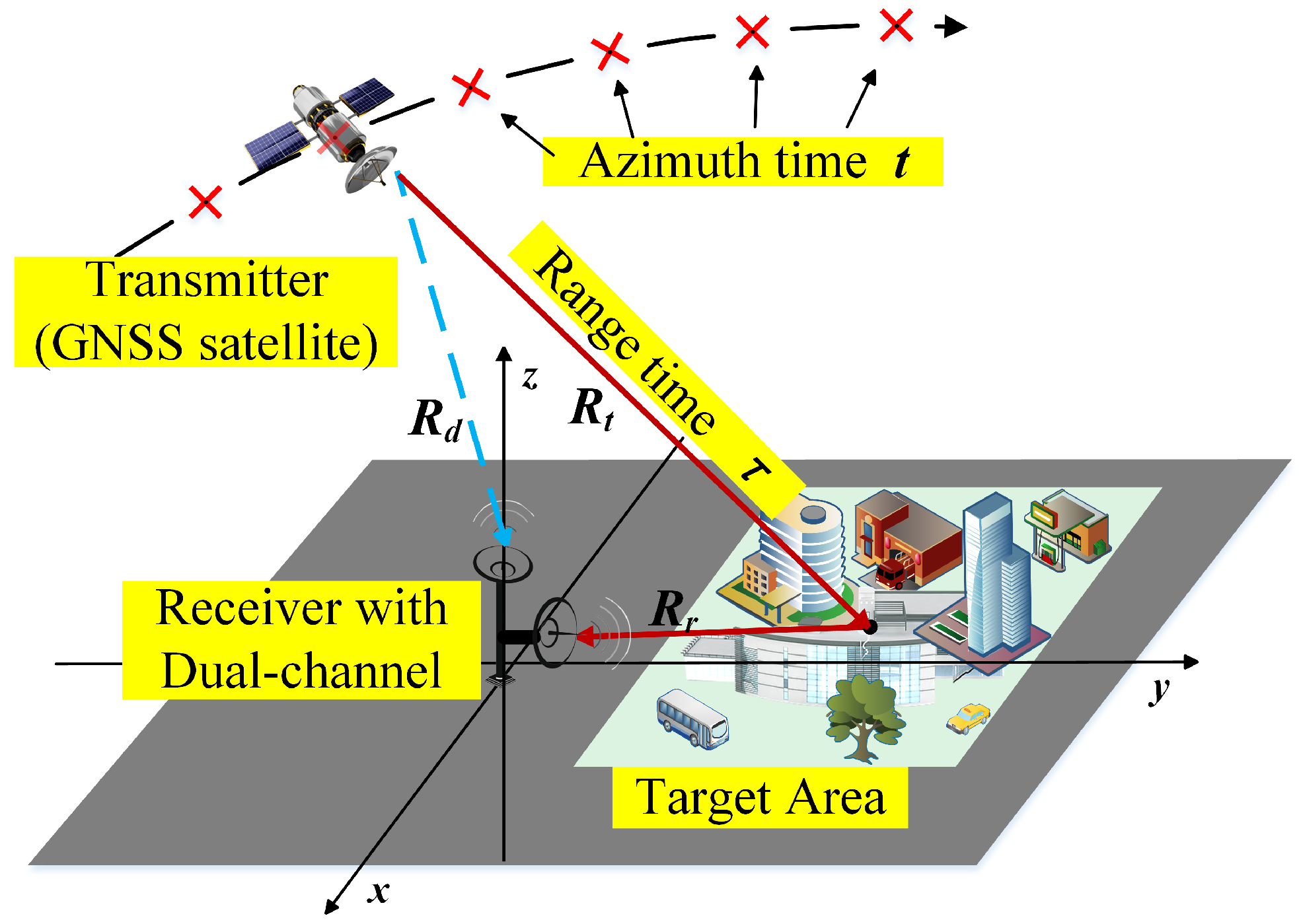
Figure 1. The system configuration of the studied GNSS-BSAR system.
Remotesensing 16 02345 g001
Figure 2. Typical structure of a GNSS signal (taking GPS as an example).
Remotesensing 16 02345 g002
Figure 3. Schematic diagram of two-dimensional SAR matrix formation.
Remotesensing 16 02345 g003
Figure 4. Atmospheric distribution in the GNSS-BSAR system.
Remotesensing 16 02345 g004
Figure 5. The variation of range delay error and QPE with the TEC of the ionosphere. (a) The variation curve of range delay with TEC; (b) the variation curve of QPE with TEC.
Remotesensing 16 02345 g005
Figure 6. Ionospheric scintillation phase error (CkL = 1032, CkL = 1033 and CkL = 1034).
Remotesensing 16 02345 g006
Figure 7. Principle diagram of the classic BPA.
Remotesensing 16 02345 g007
Figure 8. The navigation signal receiving process in the reference channel for the GNSS-BSAR system.
Remotesensing 16 02345 g008
Figure 9. The diagram of the proposed two-step azimuth phase compensation processing.
Remotesensing 16 02345 g009
Figure 10. The constructed experimental platform.
Remotesensing 16 02345 g010
Figure 11. On-site photographs of the experiment taken at different times of the day: (a) in the morning, (b) at midday, (c) in the evening.
Remotesensing 16 02345 g011
Figure 12. The illustration of the experimental scene.
Remotesensing 16 02345 g012
Figure 13. GPS satellite acquisition results and sky map. (a) Sky map at the test time; (b) acquisition results at the test time.
Remotesensing 16 02345 g013
Figure 14. The reference channel carrier frequency tracking results.
Remotesensing 16 02345 g014
Figure 15. Comparison of the theoretical value and the measured value of the reference phase.
Remotesensing 16 02345 g015
Figure 16. Reference channel Doppler phase errors extraction results from three sets of experimental results. (a) In the morning; (b) at midday; (c) in the evening.
Remotesensing 16 02345 g016
Figure 17. Imaging results before and after ionospheric scintillation error compensation: (a1) imaging results before phase error compensation (morning); (a2) imaging results before phase error compensation (midday); (a3) imaging results before phase error compensation (evening); (b1) imaging results after phase error compensation (morning); (b2) imaging results after phase error compensation (midday); (b3) imaging results after phase error compensation (evening).
Remotesensing 16 02345 g017
Figure 18. Comparative analysis of actual data processing results. (a) Result of the proposed method; (b) result using traditional PGA.
Remotesensing 16 02345 g018
Figure 19. Comparison of azimuth profiles of strong scattering points. (a) First set of experiments in the morning; (b) second set of experiments at noon; (c) third set of experiments in the evening.
Remotesensing 16 02345 g019
Figure 20. Incoherent accumulation results of three SAR images (Before phase error compensation).
Remotesensing 16 02345 g020
Figure 21. Incoherent accumulation results of three SAR images (after phase error compensation).
Remotesensing 16 02345 g021
Figure 22. Overlapped result of the focused SAR image and the optical image.
Remotesensing 16 02345 g022
Table 1. The parameters used in the experiment.
QuantityValueQuantityValue
Satellite signal sourceGPS L5 PRN 4Pulse width1 ms
Signal bandwidth20.46 MHzEquivalent PRF1000 Hz
Receiver IF139.95 MHzReflect antenna gain12 dBi
Sampling Rate62 MHzIntegration time300 s
Table 2. Parameter settings of the proposed algorithm.
NaNinNxNydxdy
300,0001630016055
Disclaimer/Publisher’s Note: The statements, opinions and data contained in all publications are solely those of the individual author(s) and contributor(s) and not of MDPI and/or the editor(s). MDPI and/or the editor(s) disclaim responsibility for any injury to people or property resulting from any ideas, methods, instructions or products referred to in the content.