Article

Interferometric Calibration Model for the LuTan-1 Mission: Enhancing Digital Elevation Model Accuracy

1
National Key Laboratory of Microwave Imaging, Aerospace Information Research Institute, Chinese Academy of Sciences, Beijing 100190, China
2
School of Electronic, Electrical and Communication Engineering, University of Chinese Academy of Sciences, Beijing 100049, China
3
China Center for Resources Satellite Data and Application, Beijing 100049, China
*
Author to whom correspondence should be addressed.
Remote Sens. 2024, 16(13), 2306; https://doi.org/10.3390/rs16132306
Submission received: 31 March 2024 / Revised: 13 June 2024 / Accepted: 20 June 2024 / Published: 24 June 2024

Abstract

:
The LuTan-1 (LT-1) mission, China’s first civilian bistatic spaceborne Synthetic Aperture Radar (SAR) mission, comprises two L-band SAR satellites. These satellites operate in bistatic InSAR strip map mode, maintaining a formation flight with an adjustable baseline to generate global digital elevation models (DEMs) with high accuracy and spatial resolution. This research introduces a dedicated interferometric calibration model for LT-1, tackling the unique challenges of the bistatic system, such as interferometric parameter coupling and the π -ambiguity problem caused by synchronization phase errors. This study validates the model using SAR images from LT-1 and Xinjiang corner reflector data, achieving interferometric phase accuracy better than 0.1 rad and baseline accuracy better than 2 mm, thereby producing high-precision DEMs with a height accuracy meeting the 5 m requirement.

1. Introduction

Digital elevation models (DEMs) fundamentally represent the Earth’s surface topography and offer essential insights for both academic and practical applications, such as landslide detection, navigation, climate research, hydrological modeling, and geospatial analysis [1,2,3,4]. Interferometric Synthetic Aperture Radar (InSAR) is an advancement in DEM technology that utilizes the phase differences between radar signals to generate precise 3D models of the Earth’s terrain [5,6,7,8]. Notably, the bistatic SAR system, which employs separate transmitters and receivers on different platforms, enhances the accuracy of DEMs [9]. This configuration allows for single-pass data collection, accelerating the data-gathering process. Furthermore, the bistatic SAR system reduces temporal decorrelation impacts in a rapidly changing environment, ensuring more reliable data [10,11].
The launch of LuTan-1 (LT-1), China’s inaugural civilian bistatic SAR satellite, marks a significant leap in Earth observation technology [12]. The LT-1 mission successfully launched two L-band SAR satellites, LT-1A and LT-1B, from the Jiuquan Satellite Launch Center on 26 January and 27 February 2022, respectively [13]. LT-1 aims to achieve DEMs with the precision of 1:50,000 scale topographic maps, with the primary requirement being precise interferometric calibration [14].
The accuracy of DEMs produced through InSAR is significantly influenced by various interferometric parameters, each affecting the height accuracy to different extents [15,16,17]. These parameters include flight altitude error, slant range error, interferometric phase error, and baseline error, with their impact on InSAR-derived heights ranging from least to most substantial [18]. Precision orbit determination is effectively employed to minimize flight altitude errors [19], and geometric calibration methods proficiently address slant range inaccuracies [20]. We primarily address the more challenging aspects of interferometric phase error and baseline error, which are more crucial than flight altitude error and slant range error for enhancing the accuracy and reliability of DEM.
Classical InSAR systems, such as the Shuttle Radar Topography Mission (SRTM) [21] and TanDEM-X [10], have set benchmarks in achieving precise interferometric calibration, which is pivotal for generating global DEMs. The SRTM used a collaborative calibration approach, employing sensitivity equations to fine-tune interferometric parameters simultaneously, thus facilitating accurate DEM production [22]. However, this method introduced coupling errors due to the simultaneous calibration of parameters, impacting the precision in assessing systematic errors. Therefore, it is crucial to employ external reference data and establish a comprehensive calibration process to mitigate the error coupling among interferometric parameters
The TanDEM-X mission, the first spaceborne bistatic SAR mission, adopted an independent calibration strategy that capitalizes on the unique error characteristics of interferometric parameters [16]. This approach achieved remarkable accuracies, with an interferometric phase precision of ±7.5 mm and baseline accuracy of 2 mm [23,24,25]. TanDEM-X’s calibration success proved its efficacy and served as a blueprint for subsequent InSAR systems like Gaofen-3 and TH-2 satellites [26], promoting advancements in interferometric calibration. Additionally, numerous studies have focused explicitly on independent baseline calibration methods [27,28,29].
Despite TanDEM-X’s formidable calibration achievements, LT-1 faces distinct challenges in adopting similar methodologies due to differences in data formats and processing chains. The critical challenges for LT-1 calibration are as follows.
A primary concern is the π -ambiguity in interferometric phases, a phenomenon unique to bistatic systems. This ambiguity arises from the synchronization link processing, where the sum of synchronization phases from two satellites results in a combined average, potentially deviating from the expected 2 n π phase ambiguity to 2 n π + π . Highlighted during the TanDEM-X mission, this issue underscores the complexity of understanding π -ambiguity’s impact on phase calibration. However, the problem of π -ambiguity remains unresolved, presenting an ongoing challenge in the field.
Moreover, the complexity of the LT-1 calibration process is compounded by its reliance on a differential global positioning system (DGPS) to compute spatial baseline vectors. The interferometric baseline vector, critical for accurately gauging the displacement between SAR antennas, cannot be directly derived from DGPS data due to the presence of temporal baselines [29]. Unlike TanDEM-X, which does not address the temporal baseline within the calibration process, LT-1 incorporates initial baseline estimation into the interferometric processing, further complicating the error coupling issue. The greater baseline length of LT-1, compared to TanDEM-X, necessitates a refined baseline model to accommodate the rapid relative satellite motion.
A further complication arises from LT-1’s operation in the L-band, known for its significant penetration capability, which introduces meters of error due to uncertain penetration depths [30,31]. However, current methods for estimating penetration depth lack precision. To mitigate this, deploying corner reflectors with a strong Radar Cross Section (RCS) is essential for calibration, as the penetration depth of the L-band is minimal on such reflective targets [32].
This study aims to develop a robust interferometric calibration model for LT-1 to address these challenges. It proposes a method for modeling interferometric phase calibration to resolve the π -ambiguity. It explicitly examines and calibrates the baseline for LT-1. Data from corner reflectors are used to calibrate baseline and interferometric phase errors accurately.
The remaining sections of this paper are structured as follows. Section 2 delves into the mechanics of interferometric calibration, detailing the flow of the process along with methodologies for absolute interferometric phase and baseline calibration. Section 3 presents an overview of the calibration sites and the SAR data utilized in this study, including a statistical analysis of interferometric phase error, baseline error, and DEM results. In Section 4, the discussion pivots to evaluating whether the precision of interferometric phase error and baseline error meets the accuracy requirements for DEM. This section also outlines future directions for this line of research. Section 5 concludes the paper, summarizing this work’s key results and contributions.

2. Methodology

2.1. Interferometric Calibration Flow

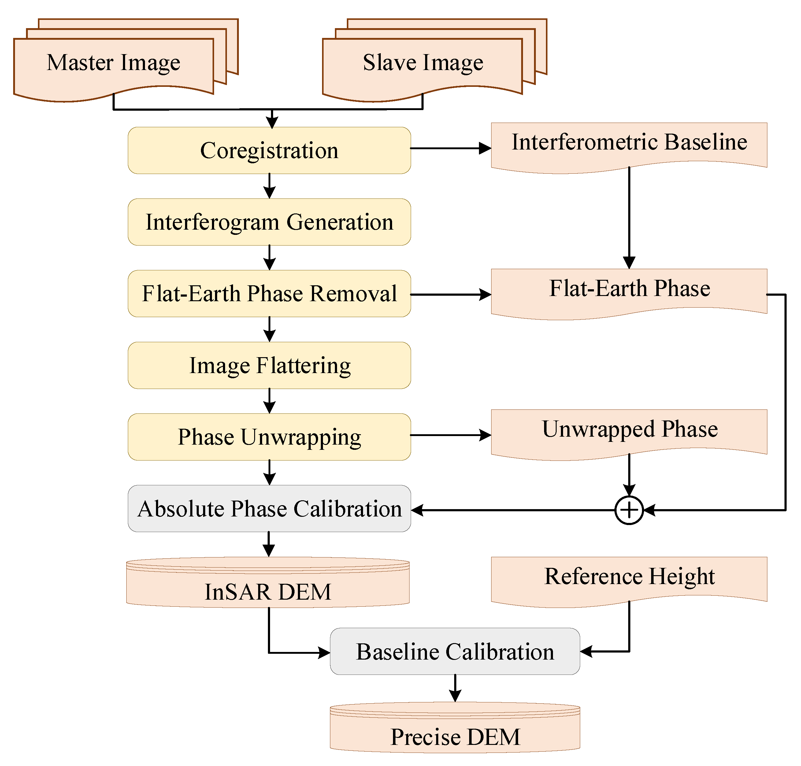
The process for calibrating the critical interferometric parameters is illustrated in Figure 1, detailing the steps involved in the interferometric calibration workflow.
(1) Coregistration. The coregistration of master and slave SAR images is achieved through the correlation coefficient method [33]. Initially, 1000 points boasting coherence coefficients above 0.9 are identified across the image. The registration offsets for these points are calculated, followed by the polynomial fitting of these offsets. Coregistration is deemed successful if the average residual of the polynomial fitted values to the actual values is under 0.06 pixels, ensuring high precision in image alignment. When traditional methods do not meet the accuracy requirements, advanced models can be used as references to obtain the registration offsets [34,35,36].
(2) Interferometric baseline derivation. Utilizing registration offsets, the relative positions of the master and slave satellites are determined. This information is crucial for computing the temporal baseline, providing a foundation for accurate interferometric baseline measurements.
(3) Interferogram generation. SAR single-look complex (SLC) images, consisting of complex data (both real and imaginary components), undergo interferometric processing. This step involves the conjugate multiplication of two SAR complex images to compute phase differences at each corresponding point, resulting in a comprehensive interferometric phase map that includes amplitude and phase information.
(4) Flat-Earth phase removal. This step is designed to counteract the influence of Earth’s topography on interferometric phase measurements [37]. In regions perceived as flat, terrain variations and the Earth’s inherent curvature generate overlaying interference fringes, complicating analyses such as phase unwrapping. By utilizing the interferometric baseline determined in a previous step and estimating the phase over a theoretically flat surface, this process subtracts the flat-Earth phase from the overall interferometric phase. This subtraction effectively isolates phase contributions due to terrain variations, simplifying the interpretation of interference fringes.
(5) Image flattering. During InSAR data analysis, unclear interference fringes, marked by “spikes” and discontinuities, can diminish the efficiency and accuracy of phase unwrapping. Addressing these anomalies is critical, as errors propagate through the phase unwrapping process. A mean filtering algorithm is applied at this juncture to refine the interferometric phase quality, paving the way for more precise analysis and interpretation.
(6) Phase unwrapping. The phase difference in an interferogram is represented by principal phase values within the range ( π , π ] . To accurately derive the actual phase difference, phase unwrapping is necessary. This critical step directly influences the height accuracy of the DEM, employing a default weighted branch cuts algorithm for phase unwrapping [38]. Should the initial results prove inadequate, alternative methodologies, such as network flow-based or minimum spanning tree-based algorithms [39], are considered.
(7) Absolute phase calibration. This crucial step addresses the residual phase offset following phase unwrapping. The radargrammetric method is employed to determine the absolute phase shift, ensuring alignment with real-world measurements and enhancing the fidelity of the DEM. This step will be elaborated further in the subsequent section.
(8) Baseline calibration. With the interferometric phase converted to the initial InSAR height, baseline calibration is performed using corner reflector heights. This final adjustment refines the baseline measurements, solidifying the accuracy of the DEM produced through the InSAR process.
(9) DEM generation. This step integrates the refined phase and baseline to obtain the DEM.

2.2. Absolute Phase Calibration Model

Discrepancies in the unwrapped phase compared to the accurate absolute interferometric phase are influenced by two primary components: the phase unwrapping algorithm’s starting point variances and the differential transmit/receive channels across the master and slave SAR systems [15,38]. Errors from the unwrapping process are categorized as algorithm-induced, distinguishing them from system-induced inaccuracies. Calibration of the interferometric phase is crucial, focusing on harmonizing the discrepancies caused by the diverse transmit/receive channels between the master and slave SARs.
Further complicating the accuracy of the absolute interferometric phase are errors introduced by phase synchronization issues between the master and slave SARs, errors arising during the imaging and interferometry processes, and phase perturbations caused by the radar’s inherent thermal noise and quantization noise [17,40]. These errors are generally random within the system. Using high signal-to-noise ratio corner reflectors can maintain these random errors within permissible bounds.
In bistatic mode, the phase of the master SAR echo and slave SAR echo at the ground point P can be expressed as follows [41]:
ϕ 1 = 2 π R 1 λ + ϕ t 1 + ϕ r 1 + ϕ p 1 + ϕ n 1 + arg S p q 1
ϕ 2 = 2 π R 2 λ + ϕ t 1 + ϕ r 2 + ϕ p 2 + ϕ n 2 + arg S p q 2
where ϕ 1 is the phase of the master SAR echo; ϕ 2 is the phase of the slave SAR echo; λ is the wavelength; 2 π R λ is the phase caused by the round-trip delay of electromagnetic waves between the satellite and the ground point; ϕ t is the transmitting channel delay; ϕ r is the receiving channel delay; ϕ p is the phase error caused by the processor; ϕ n is the phase error caused by noise; arg S p q is the phase error introduced by ground targets under specific polarization; and Subscripts 1 and 2 represent master SAR and slave SAR, respectively. Given that the bistatic SAR system’s antennas receive ground echo almost simultaneously in identical polarization modes, it is logical to conclude that ground targets remain constant and that the scattering matrix is the same for both SARs.
The interferometric phase is the phase difference of two radar echo signals, and it can be expressed as follows:
Δ ϕ m = 2 π ( R 1 R 2 ) λ + ( ϕ r 1 ϕ r 2 ) + ( ϕ p 1 ϕ p 2 ) + ( ϕ n 1 ϕ n 2 ) + n π
where Δ ϕ m is the phase acquired by interferometric processing; 2 π ( R 1 R 2 ) λ is the phase used for interferometric height measurement, simplified as Δ ϕ ; ( ϕ r 1 ϕ r 2 ) is the phase error caused by receiving the channel delay differences of two SARs; and ( ϕ p 1 ϕ p 2 ) is the phase error caused by the processor differences of two SARs. Equation (3) can be reinterpreted accordingly:
Δ ϕ m = Δ ϕ + Δ ϕ o f f + Δ ϕ n + n π
where Δ ϕ represents the interferometric phase of interest, and ϕ = 2 π ( R 1 R 2 ) λ . Δ ϕ off denotes the phase shift caused by variations in the reception channels and processors. Δ ϕ n is the combination of two Gaussian noises and can be considered as a single Gaussian noise.
The interferometric phase obtained through the interferometric processing is Δ ϕ m , while the interferometric phase used to generate the DEM is Δ ϕ . Thus, absolute interferometric phase calibration involves extracting Δ ϕ from Δ ϕ m and identifying the phase shift Δ ϕ off in Equation (4).
The formula for the reference interferometric phase, which is determined by the corner reflector’s coordinate, is given below:
ϕ r e f = 2 π λ P S P G C P P M P G C P
where ϕ r e f is the reference interferometric phase; P M and P S are the positions of the master and slave SARs when observing the ground point, respectively; and P G C P is the position of the corner reflector.
The absolute interferometric phase calibration model is established as follows:
ϕ e r r = ϕ r e f ϕ f l a ϕ u n w
where ϕ e r r is the interferometric phase error; ϕ f l a and ϕ u n w are the flat-Earth phase and unwrapped phase, respectively.
The flat-Earth phase refers to the phase component that results from the curvature of the Earth. When SAR signals are transmitted from a satellite and reflected back from the Earth’s surface, the Earth’s curvature introduces a predictable phase shift in the received signals. This phase shift needs to be removed to isolate the phase changes caused by topography and surface displacement.
The unwrapped phase is the result of phase unwrapping. SAR signals are inherently periodic and measured modulo 2 π , meaning the phase can only be observed within a range of π to π rad. Phase unwrapping aims to reconstruct the true phase values by resolving the ambiguities introduced by this 2 π wrapping, effectively “stitching together” the wrapped phase values to produce a continuous phase map. The unwrapped phase represents the actual phase differences, which can then be used to infer topographic height.
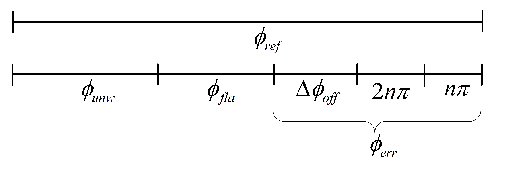
The composition of the interferometric phase is illustrated in Figure 2. The data obtained from the interferometric processing include the unwrapped phase and the flat-Earth phase. The phase error ϕ e r r derived from Equation (6) includes Δ ϕ o f f and the integer multiples of π phase shift caused by interferometric processing and phase synchronization. Therefore, to obtain Δ ϕ o f f and resolve the ambiguity in the interferometric phase resulting from phase unwrapping and the π -ambiguity caused by synchronization, it is essential to remove the integer multiples of π from ϕ e r r and retain only its fractional part as the absolute interferometric phase shift. This is achieved by performing a modulo operation of ϕ e r r with π :
Δ ϕ o f f = ϕ e r r mod π = ϕ e r r π · round ϕ e r r / π
where mod ( · ) stands for the modulo operation, and round ( · ) refers to rounding the input number to the nearest integer.
After identifying the interferometric phase error, the initial interferometric phase can be refined through specific corrective measures as follows:
Δ ϕ = ϕ f l a + ϕ u n w + Δ ϕ o f f + n π
where the term n π represents the sum of ambiguous phases introduced by the phase unwrapping and synchronization process. In regions lacking corner reflectors, the ambiguous phase can be acquired through the registration offset between the master and slave SAR images or through the utilization of external height [42].

2.3. Baseline Calibration Model

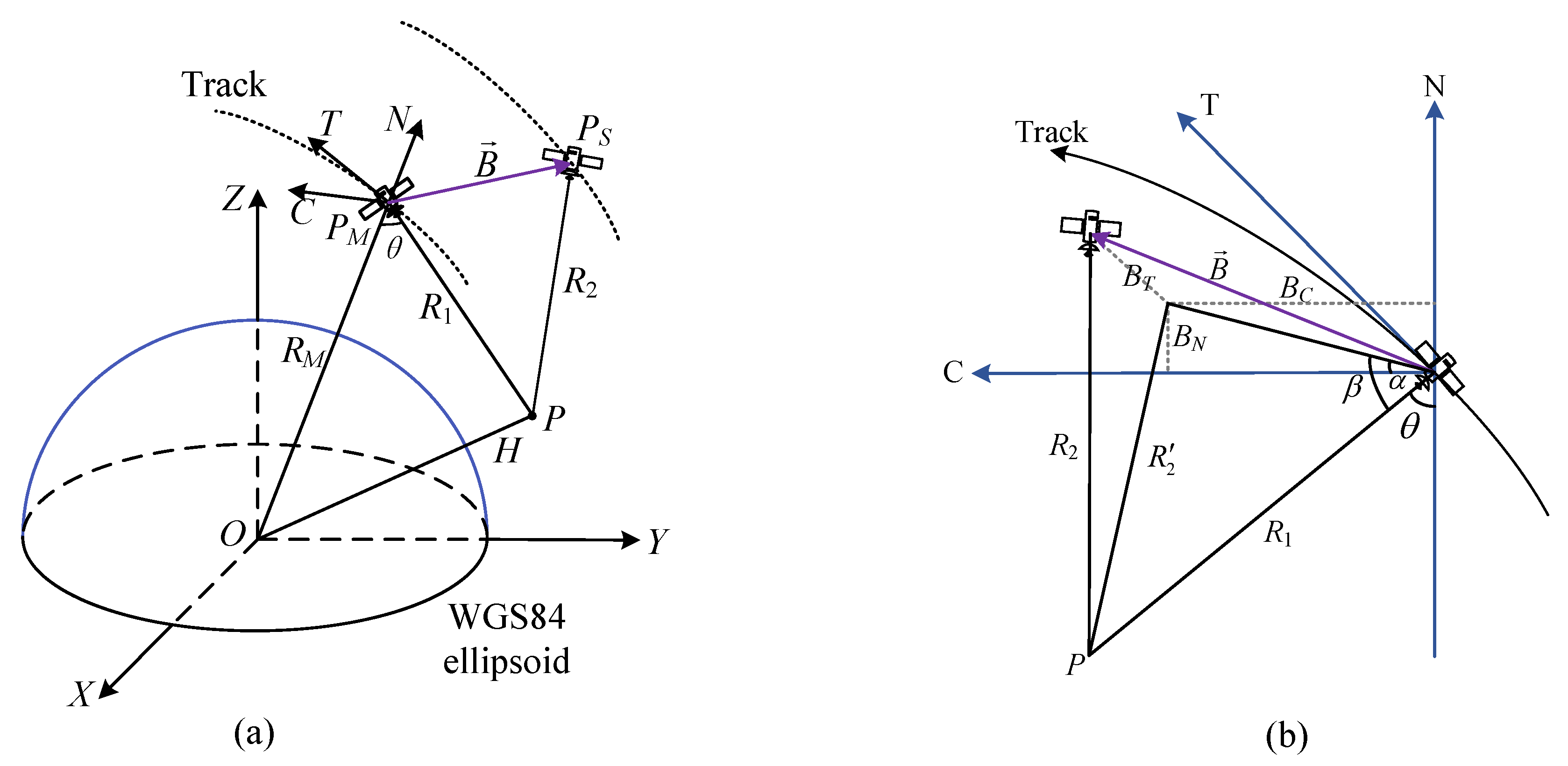
Figure 3a illustrates the geometric representation of ground point P observation within the bistatic system, showcasing two coordinate systems: the Earth-Centered, Earth-Fixed (ECEF) coordinate system and the Track Cross–Track Normal (TCN) coordinate system.
In the ECEF framework, the origin O is positioned at the Earth’s center. The Z-axis aligns parallel to the Earth’s rotational axis, directed towards the North Pole. The X-axis extends towards the equator’s intersection with the prime meridian, and the Y-axis, orthogonal to the XZ-plane, points eastward toward the equator’s crossing with the 90° east meridian.
The TCN coordinate system originates at the master SAR antenna, with the T-direction aligned along the satellite’s flight path, indicating the along-track direction. The N-direction extends from the Earth’s center towards the satellite, while the C-direction is orthogonal to the TN-plane, ensuring a right-handed coordinate system.
As depicted in Figure 3a, P M and P S represent the positions of the master SAR and the slave SAR, respectively. R 1 and R 2 are the slant ranges from the master and slave SAR to the ground point P, respectively. R M is the distance from the master SAR to the Earth’s center. H denotes the height of point P from the Earth’s surface. B represents the interferometric baseline, which is defined as the vector difference between the positions of the two satellites when observing the same ground point. Typically, the two satellites do not observe the same point on the ground simultaneously. Therefore, the interferometric baseline can be defined as follows:
B E C E F = P S ( t S ) P M ( t M ) = B X B Y B Z
where B X , B Y , and B Z are the baseline components along the X-axis, Y-axis, and Z-axis, respectively; t S and t M are the acquisition times of point P in the slave and master images, respectively. The relationship between t S and t M is as follows:
t S = t M Δ x a z t s a
where Δ x a z is the azimuth shift obtained by the coregistration step, and t s a is the azimuth sampling time.
The baseline vector is projected from the ECEF coordinate system onto the TCN coordinate system:
B T C N = t c n · B E C E F = B T B C B N
where t , c , and n represent the unit vectors of the T-axis, C-axis, and N-axis, respectively. B T , B C , and B N represent the baseline components along the T-axis, C-axis, and N-axis, respectively.
Baseline calibration primarily focuses on identifying the baseline errors in the C-axis and N-axis, which correspond to the cross-track and radial baseline errors in the TanDEM-X system, respectively [24]. Due to its minimal effect on height measurement, the baseline error in the T-axis is typically not addressed by calibration, and it can be effectively corrected through coregistration. The vector representing baseline errors is formulated as follows:
B e r r = 0 Δ B C Δ B N
where Δ B C and Δ B N represent the baseline errors in the C-axis and N-axis, respectively.
Therefore, the precise baseline is as follows:
B p r = B T C N + B e r r
Applying the phase-to-height conversion, we calculate the height of point P:
H = R M 2 + R 1 2 2 R M R 1 cos θ R e
where R e is the radius of the Earth, and θ is the incidence angle.
Based on the geometric relationship depicted in Figure 3b, the incidence angle can be solved as follows:
θ = π 2 β α = π 2 arccos B C N 2 + R 1 2 R 2 2 2 B C N 2 R 1 2 arccos B C B C N
where α is the elevation angle of the baseline; B C N is the baseline vector in the CN-plane, and B C N = B C 2 + B N 2 ; β is the angle between the baseline B and the slant range R 1 ; and R 2 2 is the length of the projection of R 2 onto the CN-plane:
R 2 2 = R 2 2 B T 2 = R 1 + λ 2 π ϕ 2 B T 2
where ϕ is the absolute interferometric phase.
By contrasting InSAR-derived height with the reference height H r e f , we can ascertain the baseline error by formulating the following equation:
H r e f H B p r = 0
where H B p r represents the InSAR height generated with the baseline B p r . The solution of Equation (17) is as follows:
B ^ e r r = arg min B e r r H r e f H ( B T C N + B e r r )
where H is a matrix composed of the height of several point targets.

3. Results and Analysis

3.1. Study Area and Datasets

The chosen calibration site must meet three key criteria. First, it should have predominantly flat topography to minimize elevation errors associated with the misplacement of image control points and to prevent SAR shadowing effects, ensuring high image quality. Second, the site must feature an exposed, unvegetated landscape to avoid low-coherence areas such as those covered by vegetation or water, thereby enhancing the signal-to-noise ratio. Lastly, the area should exhibit arid conditions with little to no precipitation, maintaining a stable environment with minimal landform changes.
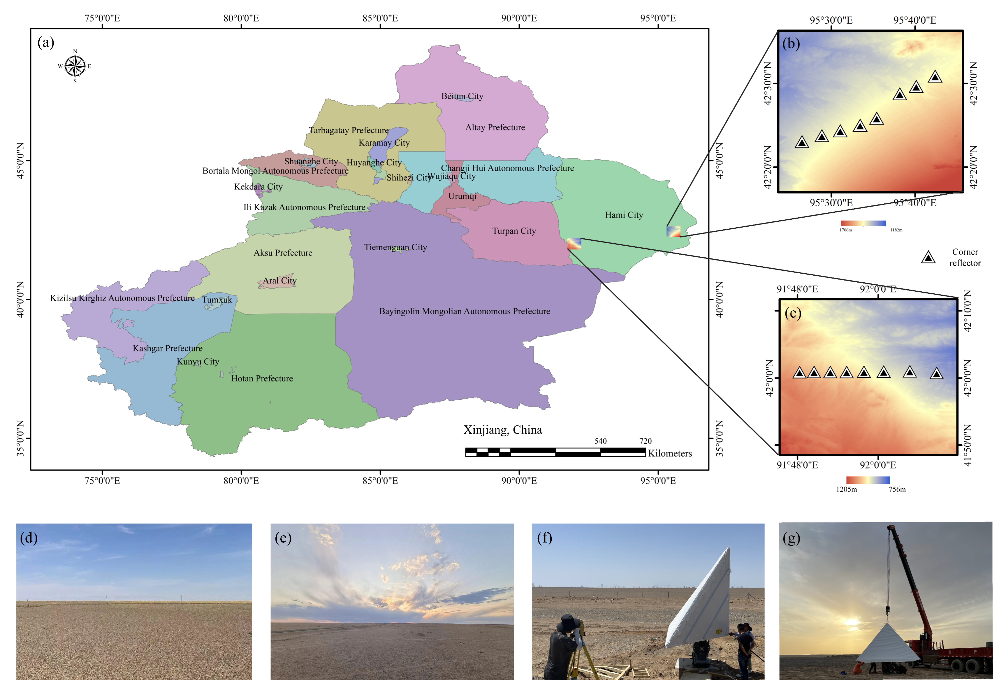
The study area in the Hami South Gobi region of Xinjiang is depicted in Figure 4. It is selected for its suitability as a natural calibration site for interferometric SAR and fulfills all site selection criteria. The region is notably flat, with an average slope of less than 2.3°, and features sparse vegetation consisting mainly of sand, exposed rocks, and gullies. Characterized by a temperate continental climate with minimal annual rainfall and consistently low soil moisture, the area’s topography remains stable, preserving the backscattering coefficient’s consistency year-round.
At our chosen calibration site, 16 three-meter triangular corner reflectors were deployed, with their locations marked by triangles in Figure 4b,c. These reflectors were chosen for their defined geometric centers and high RCS peaks. Figure 4b depicts LT-1’s observations of the near-range swath at a 21° looking angle, designated as test site A, while Figure 4c presents the far-range swath observations at a 41° looking angle, identified as test site B. Each site hosts eight corner reflectors for calibration. The deployment was designed to investigate the impact of the looking angle on interferometric parameter error.
Two satellite formations were conceived for LT-1 to conduct interferometric height measurements. Formation 1 ensured Chinese territory coverage, and Formation 2 achieved global reach to 85° latitude. These formations dictated the slave satellite’s orbit relative to the master satellite.
In the operational phase, the LT-1A and LT-1B satellites successfully executed Formation 1’s flight plan in June 2022, followed by detailed observations of the study area’s corner reflectors in July. In mid-September 2022, the satellites transitioned to Formation 2 and continued their observations. This operational timeline allowed us to select LT-1 data spanning July to November for a comparative analysis of interferometric errors under both formations. The selected LT-1 SAR images for interferometric calibration are shown in Table 1.

3.2. Interferometric Phase Shift

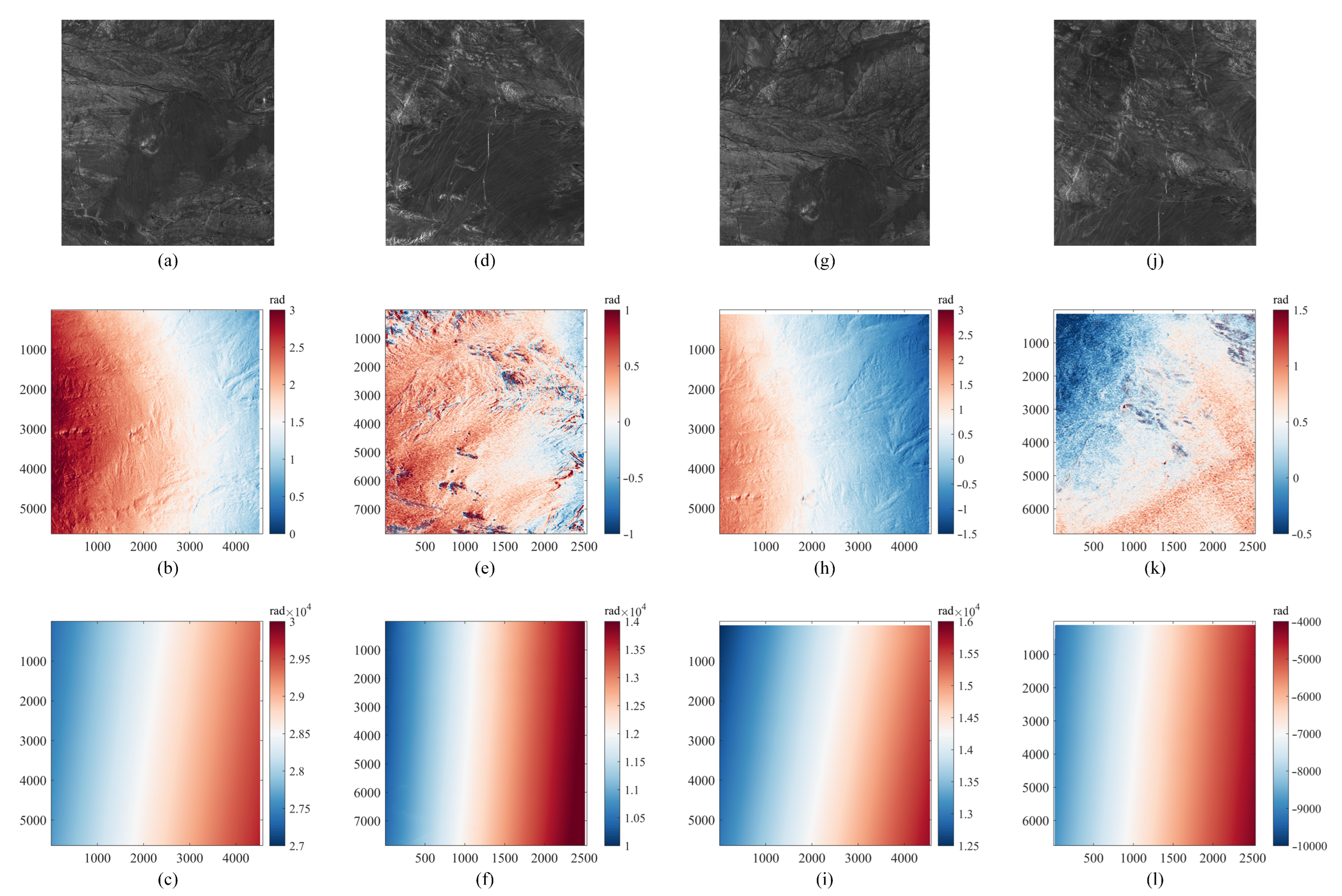
We begin by detailing the interferometric phase shift results using four distinct SAR image sets from LT-1, targeting different test sites and formations. The datasets include an image of test site B under Formation 1 (Figure 5a), an image of test site A under Formation 1 (Figure 5d), an image of test site B under Formation 2 (Figure 5g), and an image of test site A under Formation 2 (Figure 5j), with their respective SceneIDs being 29607, 30278, 49960, and 51501. The corresponding unwrapped phase results from interferometric processing are depicted in Figure 5b,e,h,k, while the flat-Earth phases are illustrated in Figure 5c,f,i,l.
The unwrapped phase results of the LT-1 data, as illustrated in Figure 5b,e,h,k, demonstrate robust performance, notably free from blocking or unwrapping errors. The process utilizes the combined unwrapped phase and flat-Earth phase from Figure 5 for interferometric phase calibration. We extract interferometric phase values at specific calibration points by sampling the interferogram. These values are then deducted from the reference interferometric phase, derived from Equation (5), to ascertain the initial phase error. Following this, the phase shift is calculated in accordance with Equation (7). The initial phase error and phase shift are detailed in Table 2.
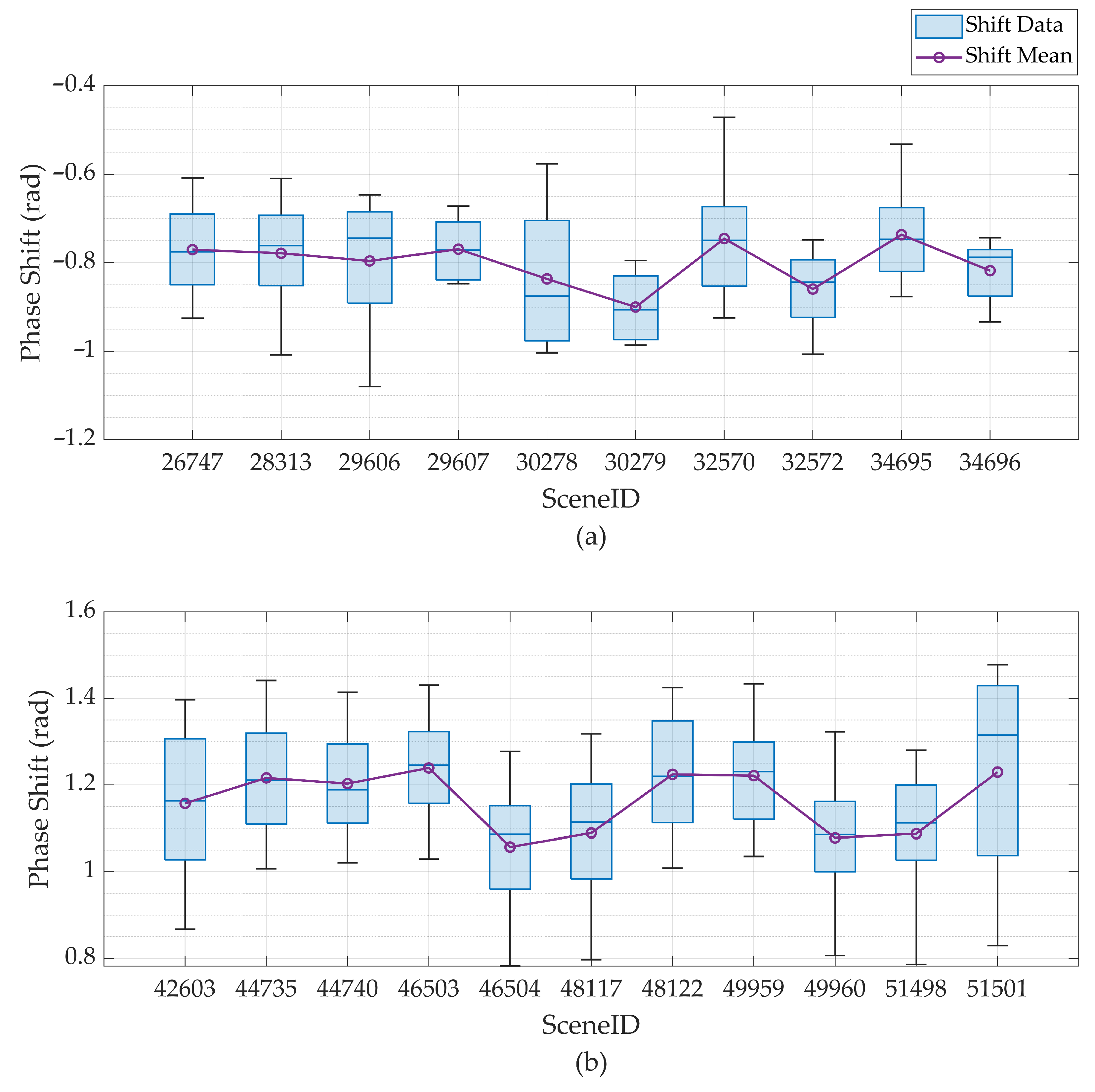
The analysis in Table 2 highlights variations in phase shift measurements across images from the same formation, indicating phase errors of −0.76 rad for SceneID 29607 and −0.83 rad for SceneID 30278, resulting in a 0.07 rad difference between them. Additionally, phase errors for SceneIDs 49960 and 51501 are 1.07 rad and 1.22 rad, respectively, showing a 0.15 rad difference. There is a notable 1.83 rad disparity between SceneIDs 29607 and 49960, despite being captured using the same range beam. This points to satellite formation as the primary factor influencing phase shift discrepancies, rather than the beam and looking angle. These observations are visually summarized in Figure 6, depicting the interferometric phase shift variations across different formations.
For each selected SAR image, eight calibration points generate a corresponding set of eight interferometric phase shift measurements. A box chart is constructed for each scene to depict the distribution of these phase shifts visually. This chart includes a rectangular box outlining the interquartile range of the data, with a horizontal line marking the median. Whiskers extend from the box to denote the minimum and maximum values. In Figure 6, the mean values are represented by purple circles. For instance, SceneID 26747 showcases phase shift extremes of −0.61 rad (maximum) and −0.92 rad (minimum). The dataset’s middle 50%, shown by the blue box, spans from −0.84 rad to −0.69 rad, with the median depicted as a blue horizontal line at −0.78 rad and the mean marked by a purple circle at −0.77 rad.
Aggregating the phase shift measurements, the average phase shift for images under Formation 1 is −0.80 rad, with a standard deviation of 0.049 rad. Additionally, the average phase shift in Formation 2 is 1.16 rad, with a standard deviation of 0.068 rad. Employing Equation (8), the interferometric phase can be compensated.

3.3. Baseline Error

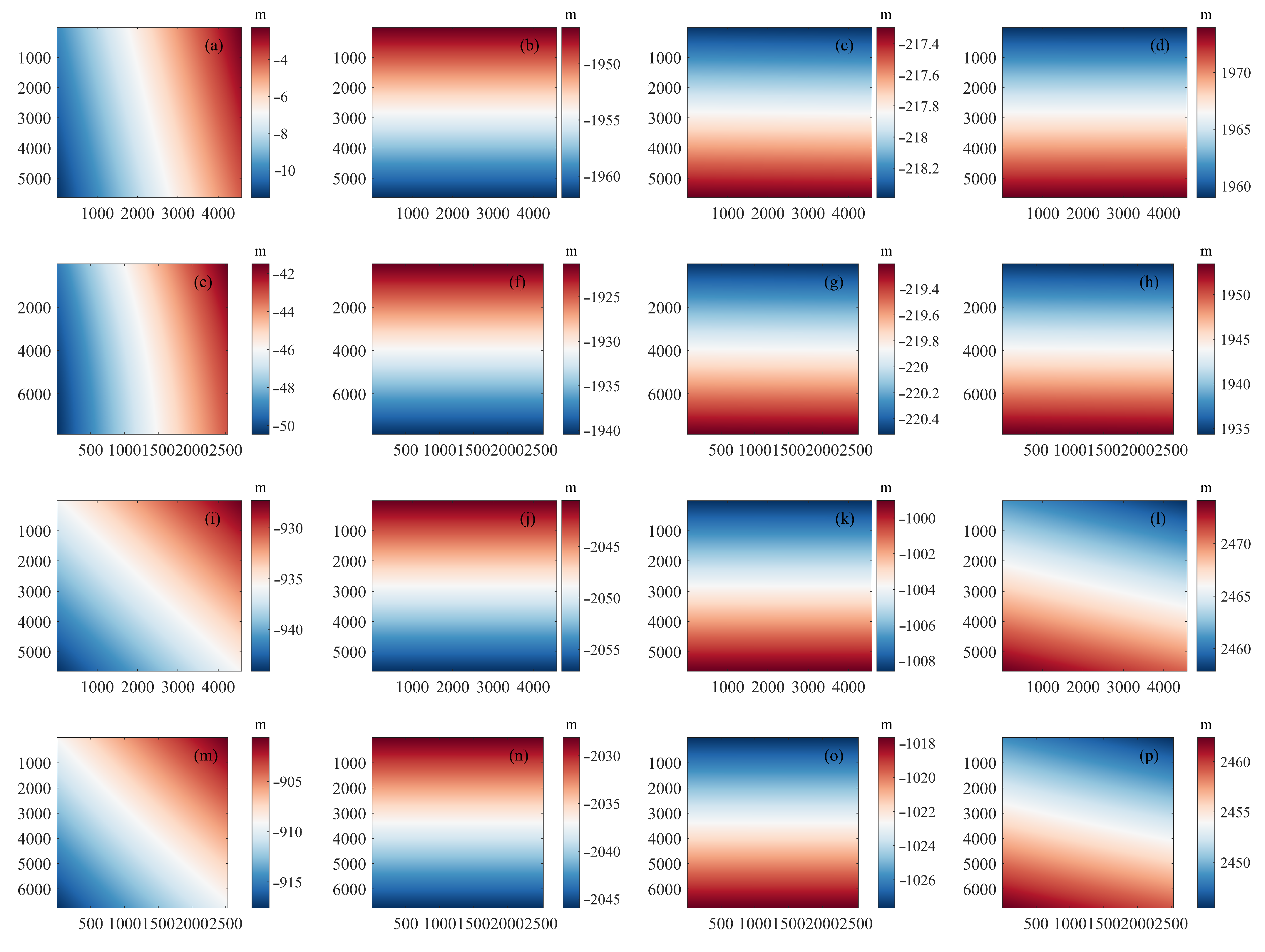
Figure 7 depicts the initial baseline of four sample data. Figure 7a–p represent the baseline values for Scenes 29607, 30278, 49960, and 51501, respectively.
Figure 7 visually distinguishes the variances between LT-1’s Formations 1 and 2, particularly highlighting two key disparities. Firstly, the T-axis (or along-track) baseline length starkly contrasts the formations. Formation 1 maintains a span of a few tens of meters, whereas Formation 2 stretches beyond 900 m. This discrepancy markedly affects the overall baseline lengths of the two formations. Secondly, the rate of change in the T-axis baseline diverges between the formations. While the C-axis and N-axis baselines exhibit nearly linear alterations over time, the T-axis baseline demonstrates nonlinear shifts. Such nonlinearity is characteristic of bistatic interferometric SAR satellites. Unlike the repeat-pass counterparts that operate via a single satellite and thus maintain nearly parallel orbits across revisits, the bistatic system features distinct orbital parameters for the master and slave satellites to sustain a helix formation, resulting in non-parallel orbits.
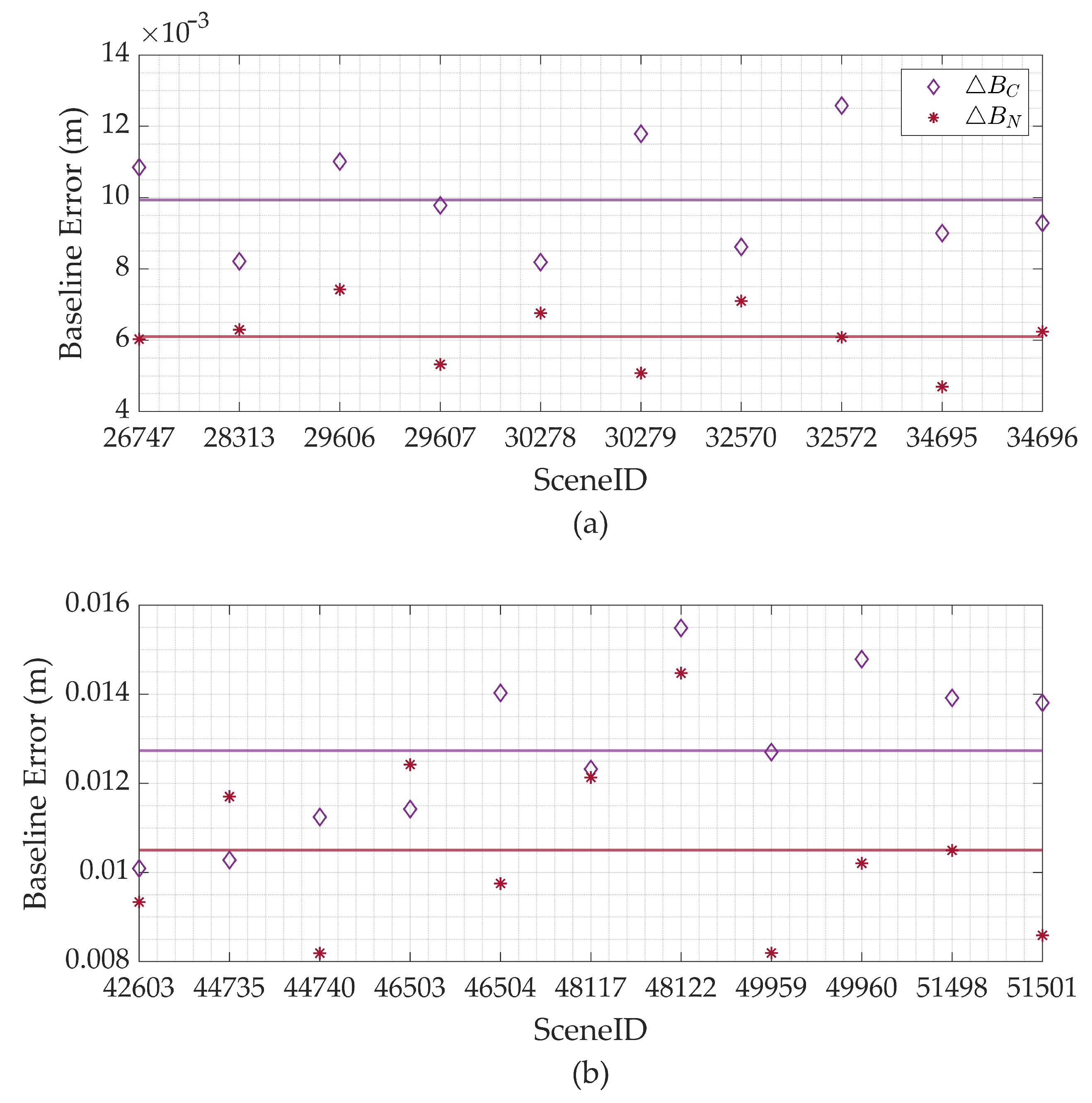
Upon adjusting for the interferometric phase shift, baseline calibration proceeds. This phase shift compensation is uniformly applied across SAR images from identical formations. The resulting baseline data are categorized into two groups corresponding to each formation. The derived baseline error outcomes for four sample datasets are compiled in Table 3. Long-term monitoring of baseline errors is graphically depicted in Figure 8. This provides insights into the stability and accuracy of the baseline measurements over time.
In Figure 8, the baseline errors along the C-axis and N-axis are depicted by purple rhombuses and red markers, respectively. Horizontal lines in matching colors show the mean values for these errors. For LT-1’s Formation 1, the C-axis shows an average baseline error of 9.93 mm (standard deviation: 1.54 mm), and the N-axis has an average error of 6.10 mm (standard deviation: 0.87 mm). In Formation 2, the average baseline errors increase to 12.73 mm for the C-axis (standard deviation: 1.82 mm) and 10.49 mm for the N-axis (standard deviation: 1.99 mm).

3.4. DEM Generation

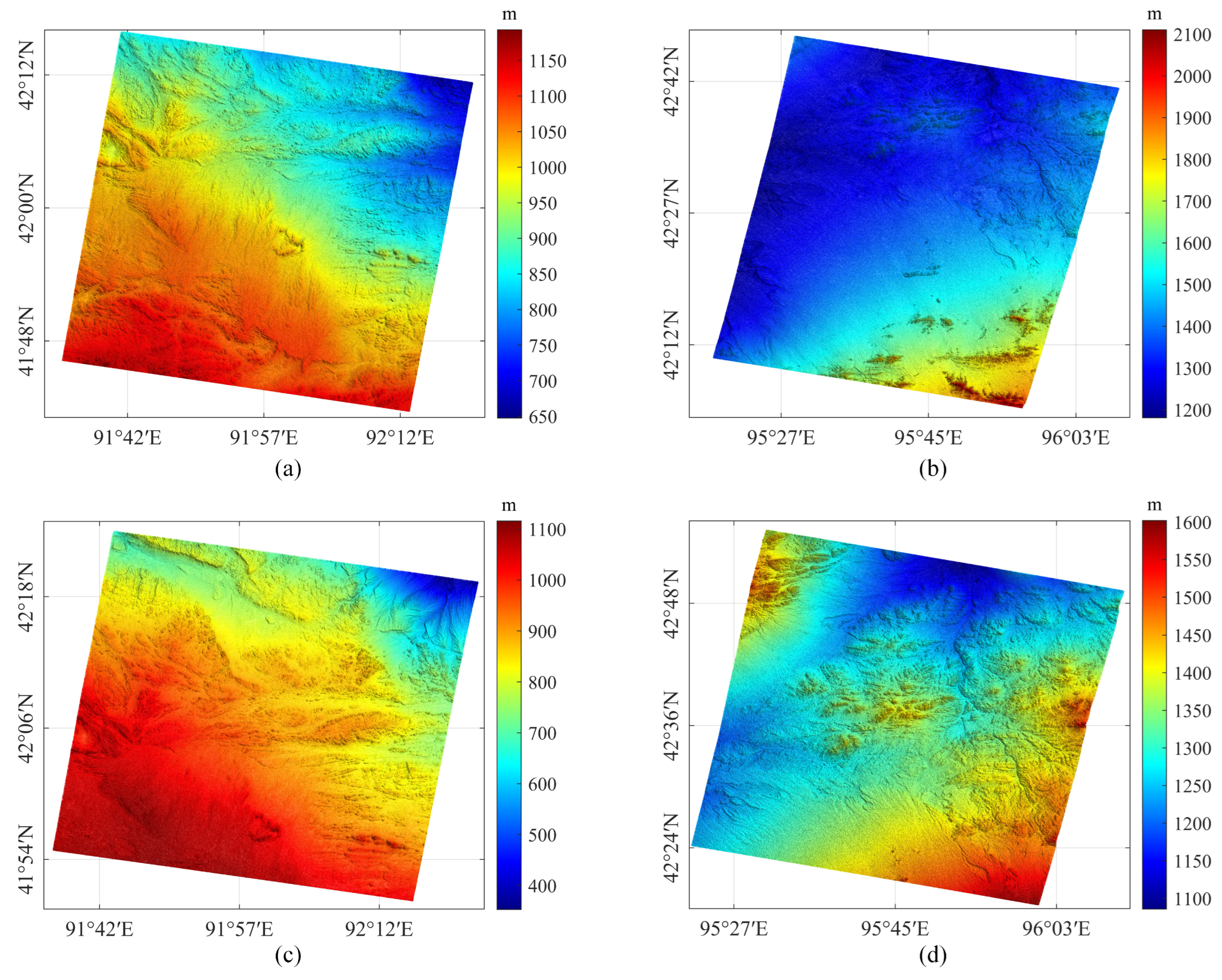
After compensating for the interferometric phase and baseline errors, DEMs for the four sample datasets are generated using the phase-to-height conversion principle, as depicted in Figure 9.
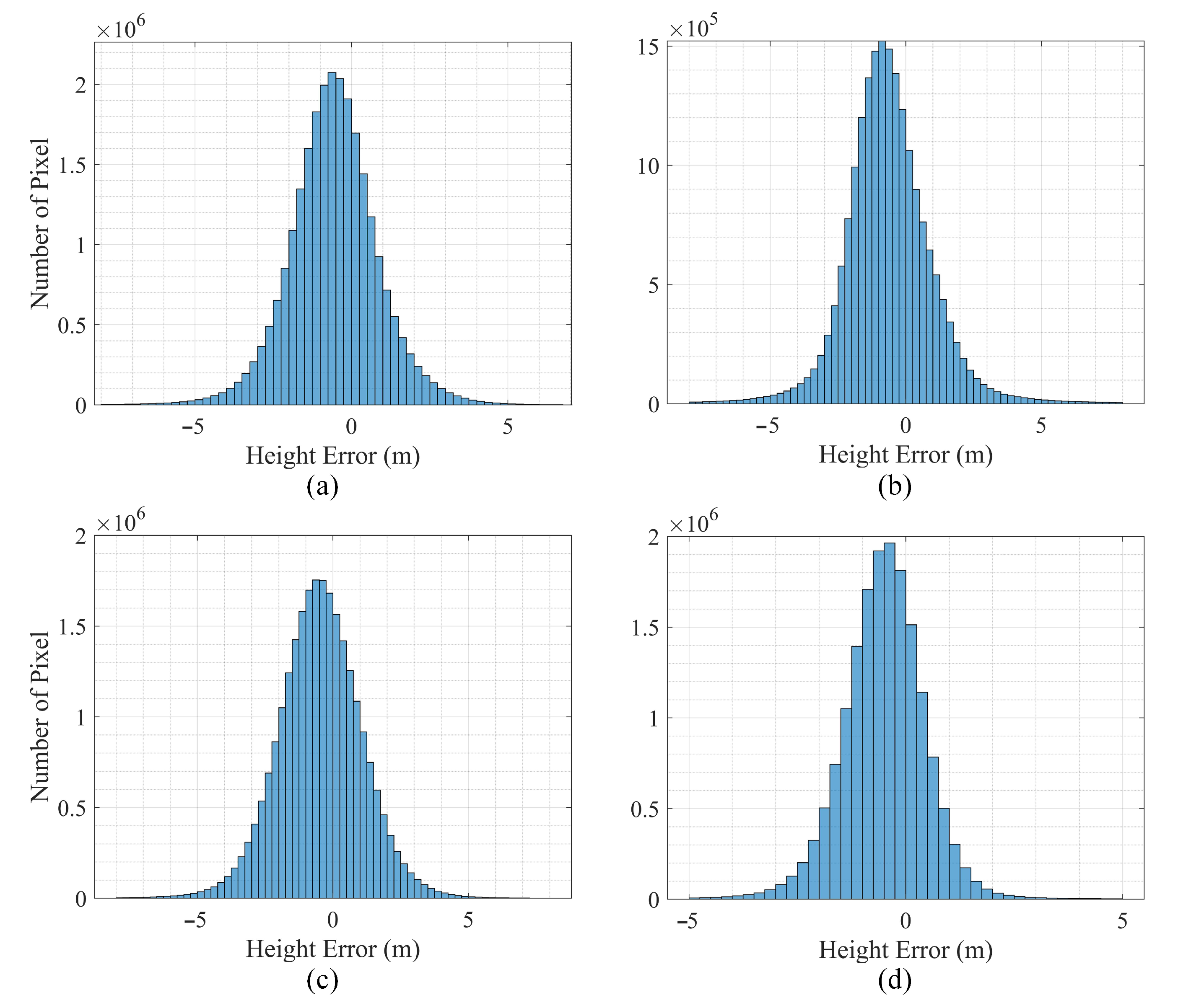
These InSAR-derived DEMs are then benchmarked against TanDEM-X DEMs, with error distributions shown in Figure 10. The comparison yields the following average height errors and standard deviations: for SceneID 29607, −0.57 m (±0.18 m); for SceneID 30278, −0.62 m (±0.41 m); for SceneID 49960, −0.47 m (±0.15 m); and for SceneID 51501, −0.51 m (±0.25 m). These findings highlight the accuracy and reliability of the InSAR DEMs relative to the TanDEM-X standards, affirming the effectiveness of the interferometric calibration and phase-to-height method in DEM generation.
The observed negative average height errors in the LT-1 DEMs are significant. The different penetration capabilities of the SAR bands primarily cause these errors. TanDEM-X’s X-band SAR contrasts with LT-1’s L-band SAR. The L-band SAR penetrates more deeply into the sandy environments of the arid Gobi desert. This deeper penetration into the dunes can result in height errors ranging from 1 to 2 m [31].
Comprehensive DEM generation from all SAR images, followed by meticulous statistical error analysis, results in an error bar graph (Figure 11). This graph showcases the mean error (red marker) and standard deviation (purple error bars). The study area’s height error predominantly ranges from −0.75 to −0.25 m. The highest standard deviation of height error is recorded at 0.58 m. These findings confirm that the derived DEMs meet the set criteria for height accuracy and highlight the impact of SAR band characteristics on DEM precision.

4. Discussion

Compared to previous work, this study highlights several innovative aspects in the calibration of the LT-1 bistatic SAR system. Our work compensates for temporal baselines and provides a more detailed calibration process, offering valuable insights for bistatic SAR interferometric calibration. By addressing challenges such as π -ambiguity and extended baseline lengths, our model improves upon previous missions like TanDEM-X. Integrating DGPS data for precise baseline estimation and employing corner reflectors to mitigate L-band penetration errors significantly enhance calibration accuracy, resulting in high-precision DEMs that meet the 5 m height accuracy requirement.
Additionally, an accuracy analysis of the interferometric phase and baseline is presented, ensuring the reliability of our results. Finally, this study outlines limitations and future recommendations to refine calibration techniques further.

4.1. Accuracy Analysis

We found that the variation in interferometric errors is more closely linked to changes in the satellite system’s formation than to alterations in the beam swath. This variation can be attributed to adjustments in the attitudes of the master and slave SAR systems following formation changes, which influence a range of errors, including attitude measurement, beam pointing control, time synchronization, and phase synchronization errors. These errors, in turn, can affect various complex processes such as internal calibration, orbit control, imaging, and synchronization, leading to changes in interferometric errors. Hence, our experimental data suggest that interferometric errors are closely associated with the system’s formation.
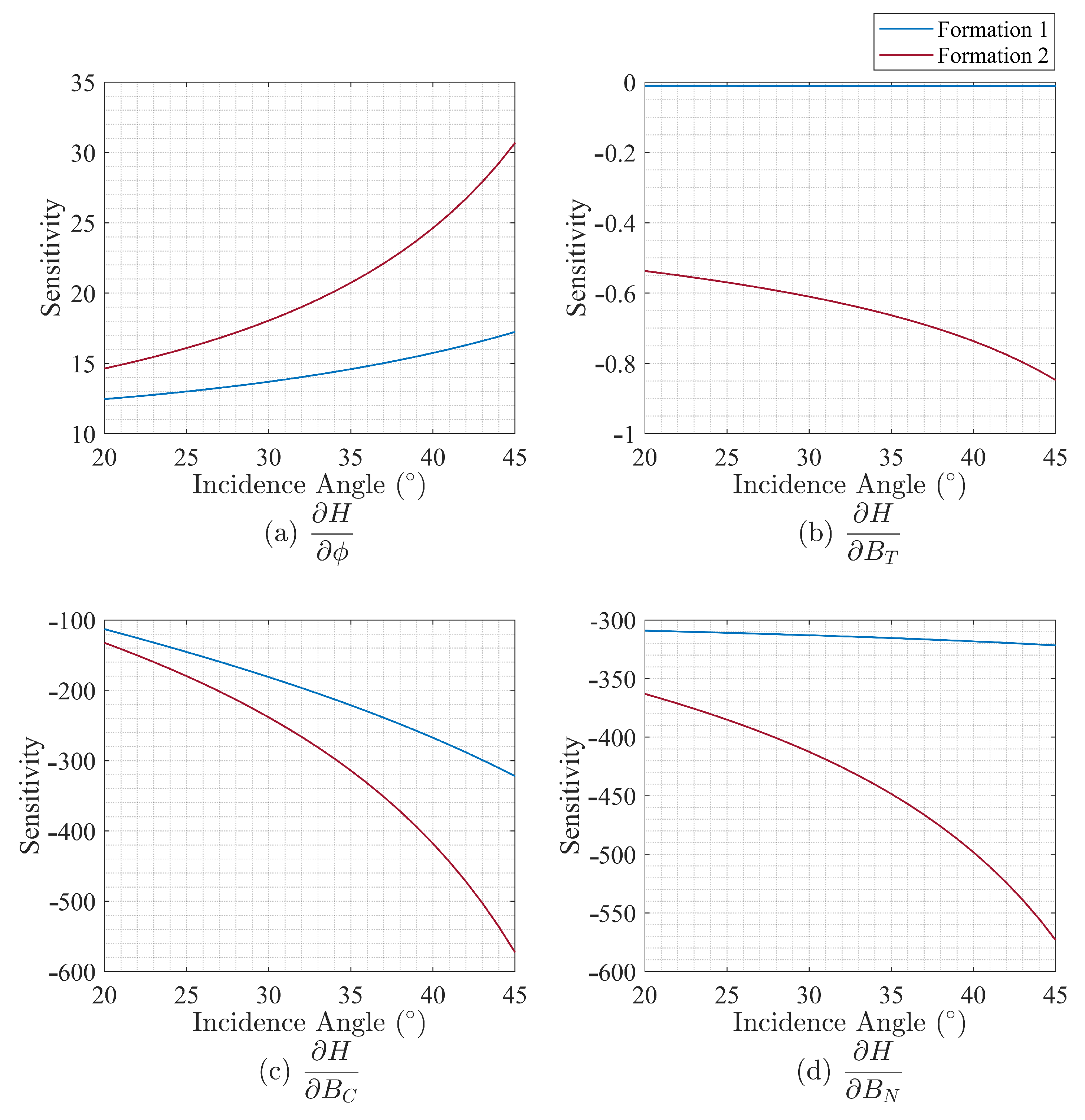
While the DEMs generated in this study fulfill the accuracy requirements, the precision of the obtained interferometric errors has not been assessed. According to the phase-to-height conversion principle, the accuracy of height measurements depends on the accuracy of the baseline length and the interferometric phase. The question arises: how do variations in baseline length and interferometric phase impact height accuracy across different formations?
This section aims to explore this by deriving the relationship between height H and variables ϕ , B T , B C , and B N through the combination of Equations (14)–(16):
H ϕ = R M λ sin θ ( R 1 + ϕ λ 2 π ) 2 π 1 a B C N H + R e
H B T = B T R M sin θ 1 a B C N H + R e
H B C = R 1 R M sin θ H + R e B C R 1 B C N 2 R 1 B C a B C N 4 3 1 a 1 B C N 3 B C 2 B N
H B N = R 1 R M sin θ H + R e B N R 1 B C N 2 R 1 B C a B C N 4 3 1 a + B C N 3 B C
where
a = ( B C 2 + B N 2 + B T 2 + R 1 2 ( R 1 + ϕ λ 2 π ) 2 ) 2 4 R 1 2 B C N 2
By inputting the parameters of LT-1 Formations 1 and 2 into the designated equations, we have determined the height error sensitivities, as showcased in Figure 12. This figure illustrates the dependency of height sensitivity on the incidence angle, with distinct representations for each formation: Formation 1 is depicted with a blue curve, while a red curve represents Formation 2. Notably, Formation 2 demonstrates a strong impact of interferometric error on height, which intensifies with an increase in incidence angle. According to Figure 12, the highest sensitivity is observed at the maximum incidence angle for Formation 2. Errors in the interferometric phase and baseline errors along the C-axis and N-axis result in significant height discrepancies.
In the analysis of LT-1 data, the precision in interferometric phase error for Formation 1 is 0.049 rad, and the baseline errors are 1.54 mm for the C-axis and 0.87 mm for the N-axis. These result in height errors of 0.85 m, −0.49 m, and −0.28 m, respectively, at the maximum incidence angle. Meanwhile, Formation 2, with precisions of 0.068 rad for the interferometric phase, 1.82 mm for the C-axis, and 1.92 mm for N-axis baseline errors, incurs height errors of 2.08 m, −1.04 m, and −1.11 m. Through numerical analysis, it is demonstrated that the accuracy of the interferometric phase and baseline measurements in this study meets the height accuracy requirements.

4.2. Limitations and Future Recommendations

In finalizing the interferometric calibration for the LT-1 system, this study has achieved stable corrections for interferometric phase shift and baseline errors. Despite these advancements, several limitations require further exploration.
First, while the calibration method has shown promising results in the flat terrain of Xinjiang, China, its effectiveness in environments with challenging interferometric qualities, such as mountainous regions, forests, and urban areas, has yet to be assessed. These complex topography and variable surface characteristics may demand tailored or alternative calibration strategies.
Second, addressing the challenge of the penetration effect inherent in the low frequency system is critical. This study mitigated this effect through calibration with point targets, which exhibit strong scattering properties and significant RCS, thus minimizing penetration effects. Future research should explore the application of distributed targets, such as those derived from ICESat laser altimetry. Obtaining distributed target data is easier, more flexible, and less costly than acquiring point target data. However, it introduces complexities in accurately estimating reference heights and interferometric phases due to the L-band’s penetration depth. Overcoming these challenges is essential for extending the applicability of the proposed method and maintaining calibration accuracy across varied environments and satellite systems.

5. Conclusions

This paper aims to conduct an interferometric calibration of the bistatic SAR system LT-1 to produce high-precision DEMs. It details the calibration process for LT-1, focusing on preventing erroneous correlations between interferometric parameters, and introduces models for absolute phase and baseline calibration specific to the bistatic SAR system. This study successfully completed its calibration experiments by leveraging corner reflector data from Xinjiang, China, and analyzing SAR data from LT-1 collected between July and November 2022.
Our results demonstrate a clear correlation between the calibration outcomes and the operational formation of LT-1, which varied over the observation period. From July to mid-September, LT-1 operated in Formation 1, then transitioned to Formation 2. Notably, Formation 2 exhibited an extended baseline length relative to Formation 1. In terms of specific values, Formation 1 yielded an interferometric phase error of −0.80 rad (standard deviation: 0.049 rad), a C-axis baseline error of 9.93 mm (standard deviation: 1.54 mm), and an N-axis baseline error of 6.10 mm (standard deviation: 0.87 mm). Under Formation 2, the interferometric phase error increased to 1.16 rad (standard deviation: 0.068 rad). The C-axis baseline error was 12.73 mm (standard deviation: 1.82 mm), and the N-axis baseline error was 10.49 mm (standard deviation: 1.99 mm).
Following the application of compensated interferometric parameters, the generated DEMs satisfied the height accuracy requirement of 5 m. Further analysis confirmed that the calibration precision is adequate for producing DEMs with a 1:50,000 scale topographic map accuracy, validating the LT-1 calibration model.
This study plans to explore interferometric calibration with distributed targets and extend height accuracy validation beyond the Gobi desert, aiming to enhance the model’s applicability and precision across diverse geographical landscapes.
Author Contributions

Conceptualization, J.M., Y.W. (Yu Wang) and J.H.; Data curation, J.H. and A.W.; Formal analysis, J.M., Y.W. (Yachao Wang) and G.L.; Funding acquisition, Y.W. (Yu Wang), J.H. and A.W.; Investigation, J.M. and S.S.; Methodology, J.M. and Y.W. (Yu Wang); Project administration, Y.W. (Yu Wang), J.H. and A.W.; Resources, J.H.; Software, J.M., Y.W. (Yachao Wang) and G.L.; Supervision, Y.W. (Yu Wang), J.H. and A.W.; Validation, J.M., Y.W. (Yachao Wang) and G.L.; Visualization, S.S.; Writing—original draft, J.M. and S.S.; Writing—review and editing, J.M. and Y.W. (Yu Wang). All authors have read and agreed to the published version of the manuscript.

Funding

This research was funded by the National Natural Science Foundation of China undergrant number 61771453.

Data Availability Statement

No new data were created or analyzed in this study. Data sharing is not applicable to this article.

Acknowledgments

The authors would like to thank the associate editor, the anonymous reviewers and the engineers who deployed the corner reflectors at the calibration site for their invaluable assistance and contributions.

Conflicts of Interest

The authors declare no conflicts of interest.

References

  1. Rossi, C.; Minet, C.; Fritz, T.; Eineder, M.; Bamler, R. Temporal monitoring of subglacial volcanoes with TanDEM-X—Application to the 2014–2015 eruption within the Bárðarbunga volcanic system, Iceland. Remote Sens. Environ. 2016, 181, 186–197. [Google Scholar] [CrossRef]
  2. Rexer, M.; Hirt, C. Comparison of free high resolution digital elevation data sets (ASTER GDEM2, SRTM v2.1/v4.1) and validation against accurate heights from the Australian National Gravity Database. Aust. J. Earth Sci. 2014, 61, 213–226. [Google Scholar] [CrossRef]
  3. Vaze, J.; Teng, J.; Spencer, G. Impact of DEM accuracy and resolution on topographic indices. Environ. Model. Softw. 2010, 25, 1086–1098. [Google Scholar] [CrossRef]
  4. Pradhan, B.; Al-Najjar, H.A.; Sameen, M.I.; Mezaal, M.R.; Alamri, A.M. Landslide detection using a saliency feature enhancement technique from LiDAR-derived DEM and orthophotos. IEEE Access 2020, 8, 121942–121954. [Google Scholar] [CrossRef]
  5. Zebker, H.A.; Farr, T.G.; Salazar, R.P.; Dixon, T.H. Mapping the world’s topography using radar interferometry: The TOPSAT mission. Proc. IEEE 1994, 82, 1774–1786. [Google Scholar] [CrossRef]
  6. Wright, T.J.; Parsons, B.E.; Lu, Z. Toward mapping surface deformation in three dimensions using InSAR. Geophys. Res. Lett. 2004, 31. [Google Scholar] [CrossRef]
  7. Geymen, A. Digital elevation model (DEM) generation using the SAR interferometry technique. Arab. J. Geosci. 2014, 7, 827–837. [Google Scholar] [CrossRef]
  8. Rosen, P.A.; Hensley, S.; Joughin, I.R.; Li, F.K.; Madsen, S.N.; Rodriguez, E.; Goldstein, R.M. Synthetic aperture radar interferometry. Proc. IEEE 2000, 88, 333–382. [Google Scholar] [CrossRef]
  9. Walterscheid, I.; Ender, J.H.; Brenner, A.R.; Loffeld, O. Bistatic SAR processing and experiments. IEEE Trans. Geosci. Remote Sens. 2006, 44, 2710–2717. [Google Scholar] [CrossRef]
  10. Zink, M.; Bachmann, M.; Brautigam, B.; Fritz, T.; Hajnsek, I.; Moreira, A.; Wessel, B.; Krieger, G. TanDEM-X: The new global DEM takes shape. IEEE Geosci. Remote Sens. Mag. 2014, 2, 8–23. [Google Scholar] [CrossRef]
  11. Zink, M.; Moreira, A.; Hajnsek, I.; Rizzoli, P.; Bachmann, M.; Kahle, R.; Fritz, T.; Huber, M.; Krieger, G.; Lachaise, M.; et al. TanDEM-X: 10 years of formation flying bistatic SAR interferometry. IEEE J. Sel. Top. Appl. Earth Obs. Remote Sens. 2021, 14, 3546–3565. [Google Scholar] [CrossRef]
  12. Jin, G.; Liu, K.; Liu, D.; Liang, D.; Zhang, H.; Ou, N.; Zhang, Y.; Deng, Y.; Li, C.; Wang, R. An advanced phase synchronization scheme for LT-1. IEEE Trans. Geosci. Remote Sens. 2019, 58, 1735–1746. [Google Scholar] [CrossRef]
  13. Cai, Y.; Li, J.; Yang, Q.; Liang, D.; Liu, K.; Zhang, H.; Lu, P.; Wang, R. First demonstration of RFI mitigation in the phase synchronization of LT-1 bistatic SAR. IEEE Trans. Geosci. Remote Sens. 2023, 61, 5217319. [Google Scholar] [CrossRef]
  14. Mou, J.; Hong, J.; Wang, Y.; Du, S.; Xing, K.; Qiu, T. LT-1 Baseline Calibration Method Based on Improved Baseline Calibration Model. In Proceedings of the IGARSS 2022-2022 IEEE International Geoscience and Remote Sensing Symposium, Kuala Lumpur, Malaysia, 17–22 July 2022; pp. 7452–7455. [Google Scholar]
  15. Crosetto, M. Calibration and validation of SAR interferometry for DEM generation. ISPRS J. Photogramm. Remote Sens. 2002, 57, 213–227. [Google Scholar] [CrossRef]
  16. González, J.H.; Bachmann, M.; Krieger, G.; Fiedler, H. Development of the TanDEM-X calibration concept: Analysis of systematic errors. IEEE Trans. Geosci. Remote Sens. 2009, 48, 716–726. [Google Scholar] [CrossRef]
  17. Mohr, J.J.; Merryman Boncori, J.P. An Error Prediction Framework for Interferometric SAR Data. IEEE Trans. Geosci. Remote Sens. 2008, 46, 1600–1613. [Google Scholar] [CrossRef]
  18. Lu, R.; Wen, J.; Zhao, D.; Liu, Y.; Hou, Y.; Chen, C. Analysis of Influencing Factors of Distributed Satellite InSAR Height-Measurement Accuracy based on Positioning Equation. In Proceedings of the 2022 3rd China International SAR Symposium (CISS), Shanghai, China, 2–4 November 2022; pp. 1–8. [Google Scholar]
  19. Li, T.; Tang, X.; Zhou, X.; Zhang, X. LuTan-1 SAR Main Applications and Products. In Proceedings of the EUSAR 2022, 14th European Conference on Synthetic Aperture Radar, Leipzig, Germany, 25–27 July 2022; pp. 1–4. [Google Scholar]
  20. Mou, J.; Wang, Y.; Hong, J.; Wang, Y.; Wang, A.; Sun, S.; Liu, G. First Assessment of Bistatic Geometric Calibration and Geolocation Accuracy of Innovative Spaceborne Synthetic Aperture Radar LuTan-1. Remote Sens. 2023, 15, 5280. [Google Scholar] [CrossRef]
  21. Farr, T.G.; Rosen, P.A.; Caro, E.; Crippen, R.; Duren, R.; Hensley, S.; Kobrick, M.; Paller, M.; Rodriguez, E.; Roth, L.; et al. The shuttle radar topography mission. Rev. Geophys. 2007, 45. [Google Scholar] [CrossRef]
  22. Sarabandi, K.; Brown, C.; Pierce, L.; Zahn, D. Calibration of the shuttle radar topography mission using point and distributed targets. In Proceedings of the IGARSS 2000. IEEE 2000 International Geoscience and Remote Sensing Symposium, Honolulu, HI, USA, 24–28 July 2000; pp. 2718–2720. [Google Scholar]
  23. González, J.H.; Antony, J.M.W.; Bachmann, M.; Krieger, G.; Zink, M.; Schrank, D.; Schwerdt, M. Bistatic system and baseline calibration in TanDEM-X to ensure the global digital elevation model quality. ISPRS J. Photogramm. Remote Sens. 2012, 73, 3–11. [Google Scholar] [CrossRef]
  24. Antony, J.W.; Gonzalez, J.H.; Schwerdt, M.; Bachmann, M.; Krieger, G.; Zink, M. Results of the TanDEM-X baseline calibration. IEEE J. Sel. Top. Appl. Earth Obs. Remote Sens. 2013, 6, 1495–1501. [Google Scholar] [CrossRef]
  25. Gruber, A.; Wessel, B.; Huber, M.; Roth, A. Operational TanDEM-X DEM calibration and first validation results. ISPRS J. Photogramm. Remote Sens. 2012, 73, 39–49. [Google Scholar] [CrossRef]
  26. Li, T.; Fan, J.; Liu, Y.; Lu, R.; Hou, Y.; Lu, J. An Improved Independent Parameter Decomposition Method for Gaofen-3 Surveying and Mapping Calibration. Remote Sens. 2022, 14, 3089. [Google Scholar] [CrossRef]
  27. Yang, Q.; Wang, J.; Wang, Y.; Lu, P.; Jia, H.; Wu, Z.; Li, L.; Zan, Y.; Wang, R. Image-based baseline correction method for spaceborne InSAR with external DEM. IEEE Trans. Geosci. Remote Sens. 2023, 61, 5202216. [Google Scholar] [CrossRef]
  28. Liu, G.; Hanssen, R.F.; Guo, H.; Yue, H.; Perski, Z. Nonlinear model for InSAR baseline error. IEEE Trans. Geosci. Remote Sens. 2016, 54, 5341–5351. [Google Scholar] [CrossRef]
  29. Xu, B.; Li, Z.; Zhu, Y.; Shi, J.; Feng, G. SAR interferometric baseline refinement based on flat-Earth phase without a ground control point. Remote Sens. 2020, 12, 233. [Google Scholar] [CrossRef]
  30. Dall, J. InSAR elevation bias caused by penetration into uniform volumes. IEEE Trans. Geosci. Remote Sens. 2007, 45, 2319–2324. [Google Scholar] [CrossRef]
  31. Qi, Y.; Wang, Y.; Hong, J.; Du, S. Additional reference height error analysis for baseline calibration based on a distributed target DEM in TwinSAR-L. Remote Sens. 2021, 13, 2750. [Google Scholar] [CrossRef]
  32. Schubert, A.; Small, D.; Gisinger, C.; Balss, U.; Eineder, M. Corner Reflector Deployment for SAR Geometric Calibration and Performance Assessment; ESRIN: Frascati, Italy, 2018. [Google Scholar]
  33. Zou, W.; Li, Y.; Li, Z.; Ding, X. Improvement of the accuracy of InSAR image co-registration based on tie points—A review. Sensors 2009, 9, 1259–1281. [Google Scholar] [CrossRef] [PubMed]
  34. Li, L.; Han, L.; Ding, M.; Cao, H.; Hu, H. A deep learning semantic template matching framework for remote sensing image registration. ISPRS J. Photogramm. Remote Sens. 2021, 181, 205–217. [Google Scholar] [CrossRef]
  35. Li, L.; Han, L.; Ding, M.; Liu, Z.; Cao, H. Remote Sensing Image Registration Based on Deep Learning Regression Model. IEEE Geosci. Remote Sens. Lett. 2022, 19, 8002905. [Google Scholar] [CrossRef]
  36. Li, L.; Han, L.; Ding, M.; Cao, H. Multimodal Image Fusion Framework for End-to-End Remote Sensing Image Registration. IEEE Trans. Geosci. Remote Sens. 2023, 61, 5607214. [Google Scholar] [CrossRef]
  37. Desai, K.; Joshi, P.; Chirakkal, S.; Putrevu, D.; Ghosh, R. Analysis of performance of flat earth phase removal methods. Int. Arch. Photogramm. Remote Sens. Spat. Inf. Sci. 2018, 42, 207–209. [Google Scholar] [CrossRef]
  38. Gutmann, B.; Weber, H. Phase unwrapping with the branch-cut method: Role of phase-field direction. Appl. Opt. 2000, 39, 4802–4816. [Google Scholar] [CrossRef]
  39. Yu, H.; Xing, M.; Bao, Z. A fast phase unwrapping method for large-scale interferograms. IEEE Trans. Geosci. Remote Sens. 2013, 51, 4240–4248. [Google Scholar]
  40. Cai, Y.; Li, J.; Wang, Y.; Yang, Q.; Zhang, Y.; Chen, Y.; Lu, P.; Wang, R. Detecting and Removing Phase Jitters for the Phase Synchronization of LT-1 Bistatic SAR. IEEE Geosci. Remote Sens. Lett. 2023, 20, 4011705. [Google Scholar] [CrossRef]
  41. Freeman, A. SAR calibration: An overview. IEEE Trans. Geosci. Remote Sens. 1992, 30, 1107–1121. [Google Scholar] [CrossRef]
  42. Rossi, C.; Gonzalez, F.R.; Fritz, T.; Yague-Martinez, N.; Eineder, M. TanDEM-X calibrated raw DEM generation. ISPRS J. Photogramm. Remote Sens. 2012, 73, 12–20. [Google Scholar] [CrossRef]
Figure 1. Interferometric calibration workflow of LT-1.
Remotesensing 16 02306 g001
Figure 2. The composition of the interferometric phase.
Remotesensing 16 02306 g002
Figure 3. The geometric diagram. (a) Illustration of the observation of ground point P within the bistatic system. (b) Baseline decomposition and projection diagram.
Remotesensing 16 02306 g003
Figure 4. Location of the calibration site. (a) Xinjiang, China. (b) Location of test site A. (c) Location of test site B. (d,e) Topographic conditions of the study area. (f,g) Deployment of corner reflectors.
Remotesensing 16 02306 g004
Figure 5. Initial interferometric phase result. (a) Master SAR image with SceneID 29607. (b) Unwrapped phase with SceneID 29607. (c) Flat-Earth phase with SceneID 29607. (d) Master SAR image with SceneID 30278. (e) Unwrapped phase with SceneID 30278. (f) Flat-Earth phase with SceneID 30278. (g) Master SAR image with SceneID 49960. (h) Unwrapped phase with SceneID 49960. (i) Flat-Earth phase with SceneID 49960. (j) Master SAR image with SceneID 51501. (k) Unwrapped phase with SceneID 51501. (l) Flat-Earth phase with SceneID 51501.
Remotesensing 16 02306 g005
Figure 6. Box chart of interferometric phase shift result. (a) Formation 1. (b) Formation 2.
Remotesensing 16 02306 g006
Figure 7. Initial baseline value. (a) T-axis baseline with SceneID 29607. (b) C-axis baseline with SceneID 29607. (c) N-axis baseline with SceneID 29607. (d) Total baseline length with SceneID 29607. (e) T-axis baseline with SceneID 30278. (f) C-axis baseline with SceneID 30278. (g) N-axis baseline with SceneID 30278. (h) Total baseline length with SceneID 30278. (i) T-axis baseline with SceneID 49960. (j) C-axis baseline with SceneID 49960. (k) N-axis baseline with SceneID 49960. (l) Total baseline length with SceneID 49960. (m) T-axis baseline with SceneID 51501. (n) C-axis baseline with SceneID 51501. (o) N-axis baseline with SceneID 51501. (p) Total baseline length with SceneID 51501.
Remotesensing 16 02306 g007
Figure 8. Baseline error result. (a) Formation 1. (b) Formation 2.
Remotesensing 16 02306 g008
Figure 9. DEM of four sample images generated by LT-1 interferometer. (a) SceneID 29607. (b) SceneID 30278. (c) SceneID 49960. (d) SceneID 51501.
Remotesensing 16 02306 g009
Figure 10. Height error histogram of four sample images. (a) SceneID 29607. (b) SceneID 30278. (c) SceneID 49960. (d) SceneID 51501.
Remotesensing 16 02306 g010
Figure 11. The accuracy of DEM.
Remotesensing 16 02306 g011
Figure 12. The sensitivity of interferometric parameters to height. (a) H ϕ . (b) H B T . (c) H B C . (d) H B N .
Remotesensing 16 02306 g012
Table 1. Selected LT-1 SAR images for interferometric calibration.
DateSceneIDOrbitIDRegionFormationOrbit DirectionIncidence Angle
7 July 2022267472418B1Descending44.42°
14 July 2022283132530B1Descending46.03°
30 July 2022296062773A1Descending24.83°
30 July 2022296072773B1Descending45.99°
7 August 2022302782887A1Descending24.76°
7 August 2022302792887B1Descending45.99°
23 August 2022325703125A1Descending24.74°
23 August 2022325723125B1Descending45.94°
8 September 2022346953365A1Descending24.77°
8 September 2022346963365B1Descending46.04°
18 October 2022426033958B2Descending45.98°
26 October 2022447354077B2Descending45.97°
3 November 2022465034196A2Descending24.66°
3 November 2022465044196B2Descending45.97°
11 November 2022481174315B2Descending45.98°
11 November 2022481224315A2Descending24.66°
19 November 2022499594434A2Descending24.67°
19 November 2022499604434B2Descending45.97°
27 November 2022514984553B2Descending45.99°
27 November 2022515014553A2Descending24.75°
Table 2. Interferometric phase shift results of four sample data.
SceneID29607302784996051501
Initial phase error (rad)18.0730.5626.1932.62
Phase shift (rad)−0.76−0.831.071.22
Table 3. Baseline error results of four sample data.
SceneID29607302784996051501
B C (mm)9.788.1814.7913.80
B N (mm)5.326.7510.218.59
Disclaimer/Publisher’s Note: The statements, opinions and data contained in all publications are solely those of the individual author(s) and contributor(s) and not of MDPI and/or the editor(s). MDPI and/or the editor(s) disclaim responsibility for any injury to people or property resulting from any ideas, methods, instructions or products referred to in the content.