Abstract
Nowadays, zenith telescope-based digital zenith cameras (DZC), such as the COmpact DIgital Astrometric Camera (CODIAC) and VErtical by STArs (VESTA), are used to determine highly precise astrogeodetic deflections of the vertical (DoVs). The CODIAC and VESTA were developed by Eidgenossische Technische Hochschule (ETH) Zurich and University of Latvia, respectively, and only two CODIACs and four VESTAs were produced. The CODIAC has an established accuracy higher than 0.05″, while the accuracy of VESTA is ~0.1″. These two DZCs, which are the most used DZCs of the last decade, were used effectively over many survey campaigns. In this study, we used both the CODIAC and VESTA to conduct simultaneous observations at the School of Management and Engineering Vaud (HEIG-VD) in Yverdon-les-Bains, Switzerland, over five nights in August 2021. Our DZC measurements with CODIAC and VESTA mark the second time that simultaneous parallel observations were made with two different DZCs. Additionally, the VESTA was never tested against another DZC through comparative simultaneous measurements. These comparative measurements between the VESTA and CODIAC allowed for VESTA precision validation and checking the agreement between the two DZCs. The results of repeated, comparative DoV observations over five nights at HEIG-VD revealed a DoV measurement precision of VESTA around 0.13–0.16″ for 15 min long observation session and 0.10–0.13″ for 50 min long observation session. Mean DoV differences between CODIAC and VESTA at HEIG-VD were 0.08″ and −0.06″ for the North–South and East–West components, respectively.
1. Introduction
The astrogeodetic deflection (or deviation) of the vertical (DoV) is the angular difference between the direction of the gravity vector or plumbline at a point on the Earth’s surface and the ellipsoidal surface’s normal through the same point for a particularly described ellipsoid [1,2]. There are several methods for determining DoV, including combining spirit levelling and global navigation satellite systems (GNSS), deriving DoV from gravimetric geoid models [3,4], but the conventional and most precise method for determining DoV is by directly observing the astronomical latitude [Φ] and longitude [Λ] using astrogeodetic systems. Geodetic latitude [φ] and longitude [λ]) are usually measured separately by GNSS receivers located at the same benchmarks. From these, the North–South (ξ) and East–West (η) components of astrogeodetic DoV can be calculated as follows (e.g., [5,6]):
ξ = Φ − φ
η = (Λ − λ) cos φ
Nowadays, state-of-the-art astrogeodetic systems—zenith telescope-based digital zenith cameras (DZCs) [7] and, most recently, the robotic total station-based astrogeodetic systems [8,9]—are used to determine highly precise astrogeodetic DoVs.
The journey of the DZC development dates back to the beginning of the new millennium. The University of Hannover and Eidgenossische Technische Hochschule (ETH) Zurich successfully developed the first two DZCs, the TZK2-D [10,11] and DIADEM [12,13], respectively. These DZCs consist of a rotating platform with telescope, charge-coupled device (CCD) assembly, tiltmeter, levelling and rotation mechanism, control computer and other equipment.
These systems inspired many researchers elsewhere to develop their own DZCs, such as in Latvia [14,15] and Turkey [16,17]. The DIADEM was recently upgraded to the COmpact DIgital Astrometric Camera (CODIAC), and two CODIACs—‘Blue’ and ‘Red’—were created. The VErtical by STArs (VESTA), a smaller and more portable DZC, was developed at the University of Latvia and reached operational status in 2016 when prototype of VESTA was manufactured [14]; additional three VESTA DZCs were manufactured in 2019.
The main applications of DoVs include geoid or quasi-geoid determinations and geoid validation, as well as other applications such as correcting precision engineering measurements [18]. CODIAC DZCs were used for various survey campaigns in Switzerland (e.g., [19,20]) and the determination of a precise gravity field and geoid slope validation surveys in USA [21,22,23]. Like the CODIAC, the Latvian DZC VESTA, was used for dense DoV measurements within Latvia; these obtained DoVs were then used for quasi-geoid determinations [24].
Since measuring DoVs with DZCs is an absolute measurement technique, systematic errors caused by, for example, unmodelled atmospheric effects or thermal deformations of the instruments may remain in the data. The atmospheric effect known as anomalous refraction is of particular interest in astrogeodetic observations, as it is the most significant source of error. Anomalous refraction refers to any deviation from the simple radial-symmetric refraction model of the atmosphere. According to this model, there should be no refraction in the zenith direction. However, anomalous refraction affects all astrogeodetic observations [25].
In order to estimate precision of DZCs, it is important to perform repeated observations at the same site over extended periods of time under various external and meteorological conditions [26]. Taking these repeated comparative measurements with at least two different DZCs at the same site is also crucial for checking agreement between DZCs.
In this study, the VESTA (Figure 1a) was brought to School of Management and Engineering Vaud (HEIG-VD) in Yverdon-les-Bains, Switzerland, for parallel measurements with the CODIACs (Figure 1b). The VESTA and CODIAC Blue were deployed over five nights (from 26 July to 12 August 2021), and on the final night, the CODIAC Red was also deployed with them. Therefore, the five overnight parallel observations were completed, resulting in a comprehensive dataset for further evaluation.
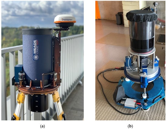
Figure 1.
(a) VESTA [24] and (b) CODIAC digital zenith cameras (DZCs).
This marked the second time that DZC simultaneous parallel observations were made with different DZCs; the first was using TZK2-D and DIADEM in 2010 [7]. Moreover, the VESTA had never previously been tested through comparative simultaneous measurements against other DZCs. This is of particular interest since the VESTA concept differs from other DZCs, especially in its DoV calculation strategy. As the CODIAC has an established accuracy higher than 0.05″ [19], the comparison between the VESTA and CODIACs allowed for the precision validation of VESTA using CODIAC as a reference, as well as determining the agreement between the DZCs.
2. VESTA versus CODIAC
Each DZC design is unique, even as they share many of the same components. This section will briefly highlight the main differences between the instrument design, observation procedures and data processing of both DZCs.
VESTA and CODIAC are comprised of the standard DZC components: telescope, tiltmeter, CCD camera, focuser, GPS receiver and antenna, control computer and base platform. The main technical components of VESTA and CODIAC are given in Table 1. There are several differences between the two DZCs. VESTA has only one two-axis Lippmann high-resolution tiltmeter (HRTM), while CODIAC uses two each of the Wyler and Lippmann single axis tiltmeters. GPS is exploited for both positioning and timing in VESTA, but only for timing purposes in CODIAC. VESTA uses a 20 cm catadioptric telescope which is lighter than the telescope of CODIAC. Meanwhile, the field of view of the VESTA is smaller, with a maximum star magnitude of 12–14. Both DZCs can be used remotely, which is the most important advantage when working in the winter season. VESTA has built-in control computer and system communication via a remote desktop connection to avoid cable connections, whereas CODIAC is connected to an external control computer but can be used remotely via an application such as teamviewer, etc. The mechanical design of VESTA enables portability, making it operable by one person, while the CODIAC has heavy mechanical structure and telescope. The mechanical components of VESTA are manufactured from aluminium, which is susceptible to thermal deformations. In contrast, CODIAC uses some invar elements to minimize thermal deformations. A comparison of the VESTA and CODIAC is provided in Table 2.

Table 1.
The technical components of VESTA and CODIAC.

Table 2.
Selected specifications of VESTA and CODIAC.
Additionally, the observation procedure differs for both DZCs. A typical VESTA session lasts approximately 30–50 min and includes 20–32 rotation positions, with 10 frames obtained at each position. Each frame includes a star image file, tiltmeter reading data and timing information. The VESTA rotating assembly can be rotated through any azimuth and is not limited to cardinal directions. When the requested number of frames in an instrument rotation position is acquired, the rotating assembly is lowered to the rotation position. Rotation to the next position and re-levelling is executed and data acquisition in the new position continues. VESTA levelling is carried out at the start of each measuring position to ensure smallness of tiltmeter corrections, and this levelling is repeated if, at the beginning of a frame acquisition, tilt is considered too big. The number of frames per position, direction and rotation angle between positions most often is controlled by a session scenario. For continuous overnight sessions, the loop mode can be selected, allowing for uninterrupted observations over multiple hours. All observation session operations are carried out automatically; the observer needs only install the system, launch the observation session after selecting session scenario and be aware of the system status.
In contrast, the CODIAC observations last approximately 15–20 min for one session; each session consists of four series of observations. The number of measurements per series can be selected in the software. Typically, either 8 or 12 measurements are performed. The following example explains the process with 12 measurements. After automatic levelling to approximately 3 arcseconds, the camera enters a short waiting time for the inclinometers to stabilize. The system then performs the first 6 CCD shots. The telescope is turned in the second position (rotation of 180° around the vertical axis) and, after a short stabilization time, 12 further CCD shots are taken. The instrument rotates back into the first position, stabilizes and the last 6 CCD shots are taken. Note that 12 measurements result in 24 CCD shots. The corresponding shots from the first and the second position are combined in post-processing to eliminate systematic effects. Tiltmeters are continuously recording during the whole acquisition, so that the values can be filtered in postprocessing. After this first series, the whole camera is automatically rotated by 90° and levelled again, to acquire another series with another azimuth. A total of 4 series is acquired for every session, allowing for a so-called azimuthal calibration [10] that removes the remaining systematic errors. The overview of the main observation steps is depicted in Figure 2.
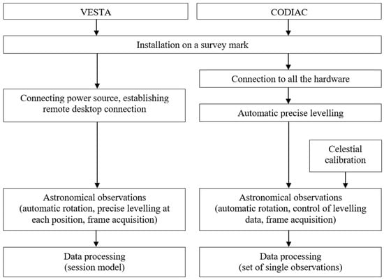
Figure 2.
Main observation steps of VESTA and CODIAC.
The basic VESTA data processing steps are: zenith area stars selection from the reference star catalogue (GAIA EDR3); accurate apparent place calculation (using the NOVAS vector astrometry package); star image identification with reference stars; and calculation of coordinates of ellipsoidal normal projection on CCD frame corrected by tiltmeter data. Calculating DoV values from VESTA measurements is different from other DZC calculations and is based on the analysis of the pattern created by the calculated coordinates of ellipsoidal normal projection on the CCD frame when the instrument is rotated. For this purpose, a session model is created, and a least square adjustment algorithm is used to determine model parameters, including both DoV components. This is carried out for a number of subsets of data contained in a sliding time interval window; a time series of DoV values for the average moment of each subset (spaced in time by duration of a position, i.e., about 2 min) is obtained as a result. The calculation of the session model is described in more detail in Zarins et al. (2016) [14] and (2018) [15].
3. Case Study
In July–August 2021, VESTA was brought to HEIG-VD in Yverdon-les-Bains, Switzerland, for comparative measurements with the CODIACs. Five overnight observations were completed during the nights of 2, 8, 9, 10 and 11 August 2021, resulting in a comprehensive dataset. Nightly measurement duration (nightly variation from 5 to 8 h) was limited mainly by cloud cover; cloud cover also did not allow for measurements during the nights of August 3–7. On the first four nights, CODIAC Blue (station 2) was deployed along with VESTA (station 1)—the setup is shown in Figure 3—while on the last night, both CODIACs, Blue (station 3) and Red (station 4), were deployed with VESTA, see Figure 4. The geodetic coordinates to calculate the DoV for stations 1, 3 and 4 were measured with a dual frequency GNSS receiver at least 30 min time intervals, and, for station 2, were obtained by long-term precise GNSS observations. The setup of the systems is shown in Figure 3 and Figure 4. Three small boreholes were drilled into the concrete slabs covering the roof to enable firm set up of the VESTA tripod. The distance between VESTA and CODIAC Blue was ~3 m, oriented in NE–SW direction, and ~1 m between CODIAC Blue and CODIAC Red.
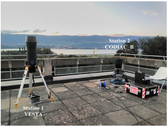
Figure 3.
Comparative measurements of VESTA and CODIAC Blue (CODIAC_B) at HEIG-VD.
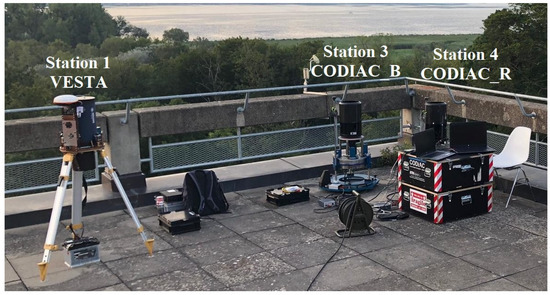
Figure 4.
Comparative measurements of VESTA and two CODIACs at HEIG-VD. CODIAC_B: CODIAC Blue, CODIAC_R: CODIAC Red.
At the start of each night’s measurements, the VESTA was set up, and the operator waited 30–60 min for VESTA to reach ambient temperature to minimize thermal deformations during the measurements. Each VESTA measurement session was controlled by a session scenario: 96 rotating positions, with 10 frames obtained at each position, and the loop mode activated to provide an uninterrupted overnight observation session. The VESTA CCD camera exposure time is 0.5 s. Approximately 2150–3300 frames per night were obtained during this study. The VESTA’s meteo sensor records temperature, pressure and humidity during measurement sessions which may assist in interpreting DoV value changes due to anomalous refraction effects.
An amount of 110 single values (each representing a 15 min session) were collected by CODIAC Blue during all five nights, and 31 values by CODIAC Red during the final observation night. Since VESTA performs continuous observations, the five nights of observations resulted in five separate time series of DoV values with total length of ~29.5 h (with an ~2 min time step within a session).
4. Results
Comparing VESTA and CODIAC measurements must consider that VESTA makes continuous measurements, and its results are represented as time series of model solutions for data subsets within a moving time window (with an ~2 min time step), while CODIAC results are set of single solutions for ~15 min long, consecutive, non-overlaying sessions. Therefore, to compare VESTA and CODIAC measurements, the authors selected individual points from VESTA time series of 12-position time window solutions with times closest to individual CODIAC session time moments. The 12 positions represent 15–18 min measurement time; therefore, it is the most appropriate number of positions for comparing against CODIAC’s 15 min long individual measurements. The selected VESTA time tags differ slightly from the CODIAC time tags by ~50 s or less, which is rather negligible. The results of both DoV components for VESTA and CODIAC over the five nights are shown in Figure 5.
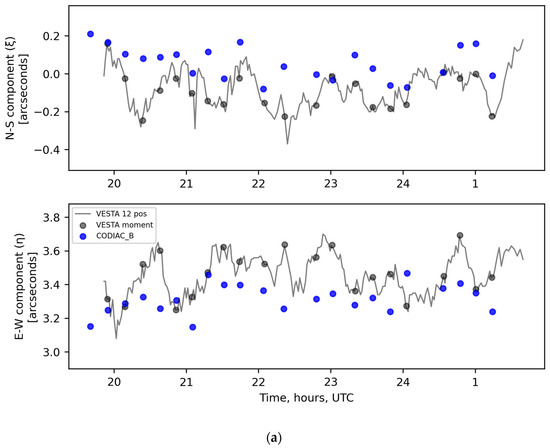
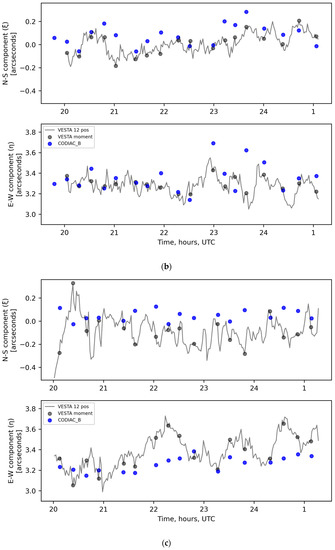
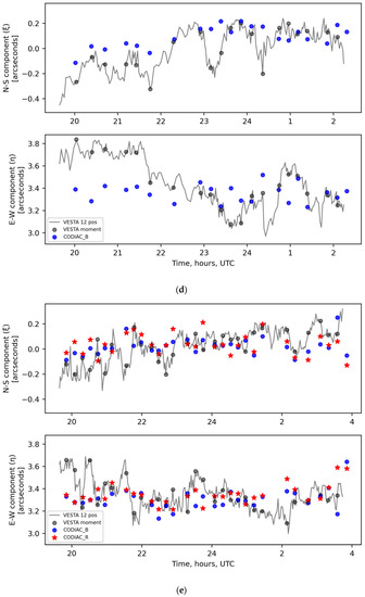
Figure 5.
Time series of both deflection of the vertical (DoV) components at HEIG-VD: (a) 2 August 2021; (b) 8 August 2021; (c) 9 August 2021; (d) 10 August 2021; and (e) 11 August 2021. Thin grey line: VESTA 12-position (~15–18 min) time window solution; grey dots: selected individual points from VESTA time series of 12-position time window solution with time closest to individual CODIAC measurement time moments; blue dots: CODIAC Blue individual measurements; red stars: CODIAC Red individual measurements.
The detailed statistical results of DoV values for each night and the mean values over the five nights are shown in Table 3. In this table, the VESTA DoV results represent the 12-position time window solutions. The comparative statistics between VESTA and CODIAC’s DoV values for each night and the mean value comparison over the five nights are shown in Table 4. The SD of the differences between those selected VESTA points and CODIAC Blue for those five nights is 0.14″ for ξ and 0.17″ for η. However, the mean difference of the five-night measurements was 0.08″ for ξ and -0.06″ for η.

Table 3.
Statistics of the nightly values for VESTA and CODIACs.

Table 4.
Differences between VESTA and CODIAC observed DoVs, and corresponding statistics.
The DoV values of VESTA (selected 12-position time window solution points) and CODIACs at the HEIG-VD stations are plotted in Figure 6. It can be clearly seen that the VESTA-measured DoV values were scattered in the direction of larger ξ values and smaller η values than the CODIAC DoV values. This effect is also represented in histograms (Figure 7), where the difference between mean ξ and η values is also visible.
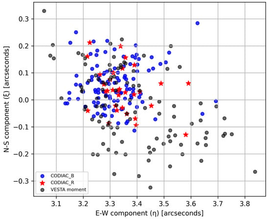
Figure 6.
The North–South (ξ) and East–West (η) components of deflection of the vertical (DoV) data for the VESTA, CODIAC Blue (CODIAC_B) and CODIAC Red (CODIAC_R) at HEIG-VD.
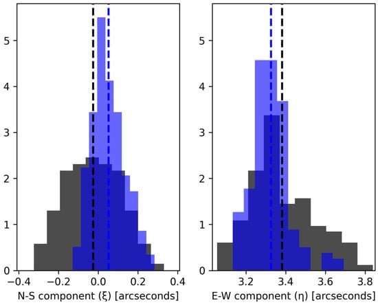
Figure 7.
Histogram of VESTA (grey) and CODIAC Blue and Red (blue) measurement results (ξ, η) obtained during the campaign. Dashed vertical lines represent corresponding mean value.
5. Discussion
The continuous 12-position time window solutions of VESTA represent low-frequency cyclical behaviour, which most likely originates from anomalous refraction effect. After selecting individual measurement points, most of this information is lost. Nevertheless, a rather sharp change in observed VESTA DoV values can be seen in the August 10 results before 22:00 UTC (Figure 5d). Meanwhile, the CODIAC E-W (η) component measurement results for August 10 were much less dispersed; however, a similar but not-as-large-as for VESTA drop in the N-S (ξ) component values can be seen before 22:00 UTC on August 10.
In Table 3, the most stable results for VESTA were from August 8 (standard deviation (SD) 0.10″ for ξ and 0.07″ for η), but for CODIAC—from August 9 (SD 0.05″ for ξ and 0.07″ for η). The largest SD for VESTA was from August 10 (0.16″ for ξ and 0.21″ for η) and from August 8 for CODIAC—(0.09″ for ξ and 0.14″ for η). The overall five-night precision of VESTA was characterized by a mean SD of 0.14″ for ξ and 0.16″ for η. In comparison, the five-night precision of CODIAC Blue was 0.08″ for ξ and 0.10″ for η. Overall, it is clear that the CODIAC 15 min observation results were less dispersed by 0.06″ for both DoV components than VESTA results of similar length.
In Table 4, the SD is similar when comparing between VESTA and CODIAC Red (one night); however, the mean difference was smaller (0.02″ for ξ and less than −0.01″ for η). The shift in ξ and η between VESTA and CODIAC Blue was more or less present for all five nights but was much smaller on the last night.
Since the standard observation session length for VESTA is 30–50 min, which corresponds to 20–32 positions, the research team selected individual points from the VESTA time series of 20 and 32 position time window solutions, which had times closest to the individual CODIAC measurement time moments, and calculated the SDs. This was carried out to understand how VESTA DoV values behave in relation to the number of measurement session positions (results in Figure 8). On most nights, the VESTA DoV value SD drops with higher number of positions. Mean SD of ξ drops from 0.14″ (12 positions) to 0.10″ (32 positions), and mean SD of η from 0.16″ to 0.13″, respectively. This means a 0.03–0.04″ improvement of precision by increasing the number of positions by 20. Additionally, the mean SD of the differences between CODIAC Blue and VESTA dropped from 0.14″ for 12 positions to 0.10″ for 32 positions for ξ and from 0.17″ to 0.15″ for η, respectively. This means that even 50 min VESTA observations resulted in a 0.02–0.03″ higher SD than the CODIAC’s 15 min observations. The mean difference of the five-night measurements between CODIAC Blue and VESTA 32 positions DoV results remained the same: 0.08″ for ξ and −0.06″ for η.
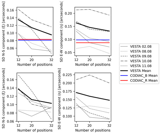
Figure 8.
Change of VESTA SD in relation to number of VESTA measurement session positions. Top—SD for VESTA and CODIAC observed DoV values; bottom—SD of differences between CODIAC Blue and VESTA.
Astrogeodetic observations are affected by atmospheric conditions. Meteorological data were recorded by a sensor installed on VESTA. The logged temperature, pressure and humidity data were inspected for any unusual behaviour (such as temperature increases over the night). However, no such unusual events were identified, the meteorological conditions over five observation nights were similar. Figure 9 presents an example of temperature, pressure and humidity logged data for August 8. Studies suggest that anomalous refraction is caused by tilted atmospheric layers that result in horizontal temperature and pressure gradients of atmosphere [29]. It is impossible to detect such gradients using a single meteorological sensor in this case. A single sensor can only detect sharp changes in meteorological parameters, such as those caused by passing warm or cold atmospheric fronts. Network of meteo sensors around the DZC observation site should be used to detect the temperature and pressure gradients.
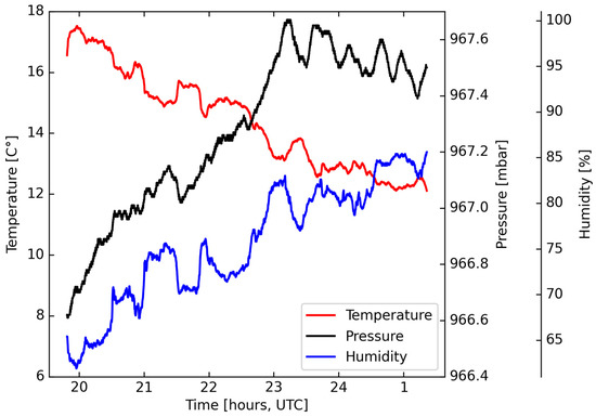
Figure 9.
Logged temperature, pressure and humidity data of VESTA meteo sensor, August 8.
6. Conclusions
This paper describes the second time that simultaneous parallel observations using different digital zenith cameras (DZCs) were made, and the first time in which the VESTA was tested through comparative simultaneous deflections of the vertical (DoV) measurements against other DZCs (CODIAC Blue and Red). The comparative simultaneous astrogeodetic observations were conducted with the VESTA and CODIAC Blue on the roof of HEIG-VD building over four nights, and with the VESTA and two CODIACs (Blue and Red) on the fifth night in August 2021.
In this research, the precision of VESTA was determined by the results of the repeated comparative DoV observations over the five nights at HEIG-VD, which revealed a DoV measurement precision of approximately 0.13–0.16″ for 15 min long observation sessions (12 position time window solutions). In contrast, the CODIAC measurement precision was approximately 0.08–0.10″ over the five nights. It was also investigated how 20 and 32 position time window solutions (30 and 50 min long sessions, respectively) of VESTA behave and their precision was determined to be approximately 0.10–0.13″ for 50 min long observation sessions.
The agreement between CODIAC and VESTA was determined by the five-night mean DoV differences between CODIAC Blue and VESTA at HEIG-VD. The CODIAC DoV results are considered the reference values in this case. The mean DoV differences between CODIAC Blue and VESTA were 0.08″ and −0.06″ for the North–South and East–West components, respectively. On the other hand, VESTA results correspond well with CODIAC Blue and Red results on fifth night—the nightly mean results are almost identical.
Although the origin of the higher dispersion within VESTA’s results cannot be clearly identified, a likely explanation might be more pronounced thermal deformations in the instrument assembly, as the main construction material is aluminium, while CODIAC uses some invar elements. Additionally, due to re-levelling after each rotation, VESTA sessions tend to be longer than comparable CODIAC sessions, therefore potentially increasing the thermal effects.
The difference between VESTA and CODIAC results may also be due to the use of different star catalogues during measurement data post-processing. VESTA utilizes the GAIA EDR3 star catalogue, whereas CODIAC uses the UCAC4 star catalogue. GAIA EDR3 provides star position accuracy at the level of better than one milli-arcsecond [27], whereas UCAC4 may contain errors of up to a few tens of milli-arcseconds [28].
Furthermore, astronomical anomalous refraction is an additional source of error that cannot be avoided in astrogeodetic methods [25,30]. Anomalous refraction effects depend on the season, and are more pronounced in summer [21], when this comparative campaign took place. Therefore, it can be assumed that the results of both VESTA and CODIAC are equally affected by anomalous refraction.
Author Contributions
Conceptualization, I.V., D.W., S.G. and M.A.; methodology, I.V. and D.W.; software, I.V., D.W., S.G. and A.Z.; validation, D.W., S.G. and A.Z.; formal analysis, I.V.; investigation, I.V., D.W. and A.Z.; resources, I.V., D.W., S.G. and M.A.; data curation, I.V. and D.W.; writing—original draft preparation, I.V. and M.A.; writing—review and editing, D.W., S.G., M.A., A.Z. and M.O.; visualization, I.V.; supervision, S.G. and A.Z.; project administration, I.V. and M.A.; funding acquisition, I.V. and M.A. All authors have read and agreed to the published version of the manuscript.
Funding
This research was supported by the European Regional Development Fund activity “Post-doctoral Research Aid”, project No. 1.1.1.2/VIAA/4/20/666 “Investigation on accuracy improvement of automated zenith camera’s VESTA deflection of vertical measurements” and the Scientific and Technological Research Council of Turkey (TUBITAK) 2219 International Postdoctoral Research Fellowship Programme (grant number: 1059B192000149).
Data Availability Statement
Not applicable.
Conflicts of Interest
The authors declare no conflict of interest. The funders had no role in the design of the study; in the collection, analyses, or interpretation of data; in the writing of the manuscript; or in the decision to publish the results.
References
- Jekeli, C. An analysis of vertical deflections derived from high-degree spherical harmonic models. J. Geod. 1999, 73, 10–22. [Google Scholar] [CrossRef]
- Featherstone, W.E.; Rüeger, J.M. The importance of using deviations of the vertical for the reduction of survey data to a geocentric datum. Aust. Surv. 2000, 45, 46–61. [Google Scholar] [CrossRef]
- Vittuari, L.; Tini, M.A.; Sarti, P.; Serantoni, E.; Borghi, A.; Negusini, M.; Guillaume, S. A comparative study of the applied methods for estimating deflection of the vertical in terrestrial geodetic measurements. Sensors 2016, 16, 565. [Google Scholar] [CrossRef] [PubMed]
- Wan, X.; Annan, R.F.; Jin, S.; Gong, X. Vertical deflections and gravity disturbances derived from HY-2A data. Remote Sens. 2020, 12, 2287. [Google Scholar] [CrossRef]
- Robbins, A.R. Deviation of the vertical. Emp. Surv. Rev. 1951, 11, 28–36. [Google Scholar] [CrossRef]
- Heiskanen, W.A.; Moritz, H. Physical Geodesy; Institute of Physical Geodesy, Technical University Graz: Graz, Austria, 1984. [Google Scholar]
- Hirt, C.; Bürki, B.; Somieski, A.; Seeber, G. Modern determination of vertical deflections using digital zenith cameras. J. Surv. Eng. 2010, 136, 1–12. [Google Scholar] [CrossRef]
- Guillaume, S.; Bürki, B.; Griffet, S. QDaedalus: Augmentation of total stations by CCD sensor for automated contactless high-precision metrology. In Proceedings of the FIG Working Week 2012, Rome, Italy, 6–10 May 2012. [Google Scholar]
- Hardy, R.; Fancher, K.; Erickson, B.; Breidenbach, S.; Ahlgren, K.; van Westrum, D.; Geoghegan, C.; Hilla, S.; Jordan, K. Performance Assessment of the Total Station Astrogeodetic Control System (TSACS). In Proceedings of the AGU Fall Meeting Abstracts, New Orleans, LA, USA, 13–17 December 2021. [Google Scholar]
- Hirt, C. Entwicklung und Erprobung Eines Digitalen Zenitkamerasystems für Die Hochpräzise Lotabweichungsbestimmung. Ph.D. Thesis, Universitat Hannover, Hannover, Germany, 2004. (In German). [Google Scholar]
- Hirt, C.; Seeber, G. Accuracy analysis of vertical deflection data observed with the Hannover Digital Zenith Camera System TZK2-D. J. Geod. 2008, 82, 347–356. [Google Scholar] [CrossRef]
- Bürki, B.; Müller, A.; Kahle, H.-G. DIADEM: The new digital astronomical deflection measuring system for high-precision measurements of deflections of the vertical at ETH Zurich. Gravity Geoid Space Mission. 2004. [Google Scholar] [CrossRef]
- Somieski, A.E. Astrogeodetic Geoid and Isostatic Considerations in the North Aegean Sea, Greece. Ph.D. Thesis, ETH Zürich, Zürich, Germany, 2008. [Google Scholar]
- Zariņš, A.; Rubans, A.; Silabriedis, G. Digital zenith camera of the University of Latvia. Geod. Cartogr. 2016, 42, 129–135. [Google Scholar] [CrossRef]
- Zarinš, A.; Rubans, A.; Silabriedis, G. Performance analysis of Latvian zenith camera. Geod. Cartogr. 2018, 44, 1–5. [Google Scholar] [CrossRef]
- Halicioglu, K.; Deniz, R.; Ozener, H. Digital astro-geodetic camera system for the measurement of the deflections of the vertical: Tests and results. Int. J. Digit. Earth 2016, 9, 914–923. [Google Scholar] [CrossRef]
- Albayrak, M.; Halicioğlu, K.; Özlüdemir, M.T.; Başoğlu, B.; Deniz, R.; Tyler, A.R.B.; Aref, M.M. The use of the automated digital zenith camera system in Istanbul for the determination of astrogeodetic vertical deflection. Bol. Cienc. Geod. 2019, 25. [Google Scholar] [CrossRef]
- Mirghasempour, M.; Jafari, A.Y. The role of astro-geodetic in precise guidance of long tunnels. Int. Arch. Photogramm. Remote Sens. Spat. Inf. Sci. 2015, XL-1/W5, 453–457. [Google Scholar] [CrossRef]
- Albayrak, M.; Willi, D.; Guillaume, S. Field comparison of the total station-based QDaedalus and the zenith telescope-based CODIAC astrogeodetic systems for measurements of the deflection of the vertical. Surv. Rev. 2023, 55, 247–259. [Google Scholar] [CrossRef]
- Albayrak, M.; Guillaume, S.; Willi, D.; Hirt, C.; Herrera Pinzón, I.D.; Marti, U.; Ozludemir, M.T.; Müller, L.; Shum, C.K. Results from the third QDaedalus astrogeodetic system observation campaign in the mountainous terrain of the Surses region in Switzerland (2021). J. Surv. Eng. 2023; accepted. [Google Scholar]
- Guillaume, S. Determination of a Precise Gravity Field for the CLIC Feasibility Studies. Ph.D. Thesis, Eidgenössische Technische Hochschule ETH Zürich, Zürich, Germany, 2015. [Google Scholar]
- Wang, Y.M.; Becker, C.; Mader, G.; Martin, D.; Li, X.; Jiang, T.; Breidenbach, S.; Geoghegan, C.; Winester, D.; Guillaume, S.; et al. The Geoid Slope Validation Survey 2014 and GRAV-D airborne gravity enhanced geoid comparison results in Iowa. J. Geod. 2017, 91, 1261–1276. [Google Scholar] [CrossRef]
- van Westrum, D.; Ahlgren, K.; Hirt, C.; Guillaume, S. A Geoid Slope Validation Survey (2017) in the rugged terrain of Colorado, USA. J. Geod. 2021, 95, 9. [Google Scholar] [CrossRef]
- Morozova, K.; Jäger, R.; Zarins, A.; Balodis, J.; Varna, I.; Silabriedis, G. Evaluation of quasi-geoid model based on astrogeodetic measurements: Case of Latvia. J. Appl. Geod. 2021, 15, 319–327. [Google Scholar] [CrossRef]
- Hirt, C. Monitoring and analysis of anomalous refraction using a digital zenith zamera system. Astron. Astrophys. 2006, 459, 283–290. [Google Scholar] [CrossRef]
- Völgyesi, L.; Tóth, G. Improvement of QDaedalus measurements with continuous detection of environmental parameters. Acta Geod. Geophys. 2021, 56, 607–622. [Google Scholar] [CrossRef]
- Prusti, T.; de Bruijne, J.H.J.; Brown, A.G.A.; Vallenari, A.; Babusiaux, C.; Bailer-Jones, C.A.L.; Bastian, U.; Biermann, M.; Evans, D.W.; Eyer, L.; et al. The Gaia mission. Astron. Astrophys. 2016, 595, A1. [Google Scholar]
- Zacharias, N.; Finch, C.T.; Girard, T.M.; Henden, A.; Bartlett, J.L.; Monet, D.G.; Zacharias, M.I. The fourth US Naval Observatory CCD astrograph catalog (UCAC4). Astron. J. 2013, 145, 44. [Google Scholar] [CrossRef]
- Taylor, M.S.; McGraw, J.T.; Zimmer, P.C.; Pier, J.R. On the source of astrometric anomalous refraction. Astron. J. 2013, 145, 82. [Google Scholar] [CrossRef]
- Hirt, C. Anomalous atmospheric refraction and comments on “fast and accurate determination of astronomical coordinates …” (Balodimos et al. 2003, Survey Review 37(290): 269–275). Surv. Rev. 2012, 44, 285–289. [Google Scholar] [CrossRef]
Disclaimer/Publisher’s Note: The statements, opinions and data contained in all publications are solely those of the individual author(s) and contributor(s) and not of MDPI and/or the editor(s). MDPI and/or the editor(s) disclaim responsibility for any injury to people or property resulting from any ideas, methods, instructions or products referred to in the content. |
© 2023 by the authors. Licensee MDPI, Basel, Switzerland. This article is an open access article distributed under the terms and conditions of the Creative Commons Attribution (CC BY) license (https://creativecommons.org/licenses/by/4.0/).