Abstract
The airborne array position and orientation measurement system (array POS) is a key device for high-resolution multi-dimensional real-time imaging motion compensation of military reconnaissance mapping. Abnormal values will appear in array POS inertial devices and measurement data in an environment of strong interference, which often leads to a decrease or even divergence in the combination accuracy. The existing detection methods based on innovation characteristics are only sensitive to measurement outliers, which are the abnormal data caused by the strong interference environment. In this paper, an improved innovation robust outliers detection method is proposed, which is valid for both measurement outliers and inertial device outliers. First, the improved outliers detection method based on the innovation of array POS is described. The gain matrix is adaptively adjusted by using the statistical characteristics of innovation. At the same time, the information distribution coefficient is adaptively adjusted by using the filtering performance of the sub filter, which realizes the detection and correction of measurement outliers. Then, the outlier detection method of inertial devices based on extrapolation prediction is added. The predicted value of the inertial device is extrapolated by the fourth-order difference method, and the outliers are recognized and eliminated by the adaptive threshold, which contributes to improving the robustness and accuracy of array POS. STD is selected in this paper to statistic the accuracy of array POS. Compared with the traditional federated Kalman filtering (KFK) methods, the accuracies of position, speed, heading angle and horizontal attitude angle of the left node and right node are all improved when there are outliers in the measurement data. Compared with the fault-tolerant federated combination method based on innovation characteristics, the accuracies of position, speed, heading angle and horizontal attitude angle of the left node and right node are all improved when there are abnormal values in the inertial device data.
1. Introduction
The array POS is composed of a high-precision main inertial measurement unit and several MPOS, which are used for the motion compensation of subarray antenna [1,2,3,4]. The array POS sometimes works in poor environments, such as with strong interference in military reconnaissance mapping, which greatly increases the probability of abnormal values in inertial devices and measurement data [5,6,7,8]. At present, the federated filtering method is the most commonly used real-time combination method of array POS, which uses the sub filters running in parallel to improve the operation speed and robustness of the system [9,10,11]. However, the federated filtering method cannot detect and correct outliers. As a result, the precision of the array POS integrated navigation is reduced or even diverged, and the imaging quality of the load is seriously affected. To solve this problem, the state chi-square detection method [12,13,14,15] and the innovation characteristic method [16,17,18] are the most commonly used outlier detection methods. However, the state chi-square detection method will be affected by the initial value error, system noise and modeling error of the POS system, which will eventually make the state recursive value deviate from the true value. In the meanwhile, the state chi-square detection method is computationally expensive, which reduces the real-time performance of anomaly detection [19]. The characteristics are counted by the innovation zero mean Gaussian white noise in the innovation characteristic method [20], and it is simple in calculation and sensitive to measurement anomalies, which is more suitable for array POS implementation combination estimation. Nevertheless, both the state chi-square detection method and the innovation characteristic method are only sensitive to the measurement of abnormal information. The anomaly of inertial device information and measurement information caused by environmental interference will be coupled into the statistical characteristics, which leads to the failure of the innovation characteristic method when the inertial data is abnormal. Thus, an adaptive fault-tolerance combined estimation method is proposed in this paper that can detect not only the anomaly of measurement information but also the anomaly of inertial devices to improve the fault tolerance of the system in an environment with strong interference. First, the simplest and fastest measurement anomaly detection method of array POS based on innovation characteristics is described. The characteristics of zero mean Gaussian white distribution in an ideal state is used to detect the measurement outliers in this method. In addition, the outlier assessment and correction algorithm of the inertial devices based on extrapolation prediction is added. The extrapolation prediction method detects and corrects outliers by analyzing the statistical characteristics of the difference between the estimated value and the original value of the data, and it has the advantages of simple operation and strong real-time performance [21] because of the use of the original information. Finally, the effectiveness of the method is verified by the semi-physical experiments under an airborne environment with strong interference.
This article is organized as follows, the array POS system is briefly introduced in Section 2. In Section 3, the principle of the improved innovation robust outliers detection method for array POS is introduced in detail. In Section 4, the semi-physical simulations are carried out, which verifies the correctness of the proposed method. Finally, the conclusions are explained in Section 5.
2. Composition of Array POS System
The array POS system is illustrated in Figure 1, which includes the main inertial measurement unit (IMU) system, several sub-IMUs, distributed multi-source information fusion processing system (FPCS), Fiber Bragg grating deformation measurement system and GNSS. With the advantages of large design freedom, good temperature stability and low optical noise, the fiber optic gyroscope is adopted in the main inertial measurement unit, which is combined with the GNSS to provide a space–time benchmark for the sub inertial measurement unit. The micro POS system is used in sub-IMU to improve the measurement accuracy of the slave node. Because micro POS has the advantages of small size, light weight and low cost, it is easier for each subarray antenna to be equipped with a sub-IMU for motion compensation. The flexible baseline deformation measurement is a key technical problem in restricting the accurate acquisition of the motion parameters of each antenna and the time-varying spatial relationship between each array element antenna. The fiber Bragg grating sensor is used to measure the displacement vector. The FPCS is not only responsible for multi-source data processing, combined filtering of main system and transfer and alignment of subsystems but also completes the information interaction with multiple types of loads. Moreover, it also stores all original data during work for later processing. The field-programmable gate array (FPGA) and digital signal processing (DSP) board are adopted in the FPCS system, which can overcome the problem of difficult data interaction caused by the relative independence of multiple single FPCS [22]. A global information fusion software is included in the array POS that can solve the problem of time–space mismatch in flexible baseline multi node motion information fusion so as to realize the high-precision measurement of imaging load motion information and relative spatial information of each sub node and the state estimation of each node.
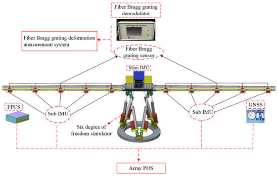
Figure 1.
The diagram of the array POS system.
3. Adaptive Outlier Fault-Tolerant Combined Estimation Model of Array POS System
As the core device of an array POS, the micro POS mainly includes a micro inertial measurement unit (MIMU), a dual antenna GNSS and a magnetometer system (MMS) [23,24]. Although it has the advantages of small size, light weight and low cost, the probability of abnormal values in its inertial devices and measurement data in a strong interference environment is greatly increased, which leads to low measurement accuracy and even failures. Thus, the detection and elimination of inertial devices and measurement outliers become extremely important. To improve the robustness of the system, the adaptive anti outlier method is added on the basis of the federated filter structure, the overall flow of which is shown in Figure 2. On the one hand, the adaptive anti outlier algorithm based on the extrapolation prediction is introduced to detect and modify the outliers of MIMU data, which realizes the anti-outlier processing at the device level. On the other hand, the adaptive anti-outlier algorithm based on innovation characteristics is adopted to detect and modify the outliers of measurement information, which realizes the anti-outlier processing at the system level.
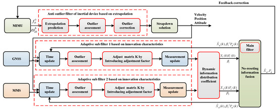
Figure 2.
The overall flow of the improved innovation robust outliers detection method.
3.1. Mathematical Model of the System
3.1.1. State Equation Mathematical Expression
Each subsystem of the array POS realizes multi-sensor information fusion by federated filtering, as shown in Figure 2. MIMU is the primary reference system, which can obtain the position, velocity and attitude information via strapdown solution. Additionally, there are two sub filters. MIMU and GNSS constitute sub filter 1, while MIMU and the magnetometer measurement system (MMS) constitute sub filter 2. The measurement information is input into the corresponding sub filter, and the results are transmitted to the main filter after filtering, which can achieve the global state estimation.
The state equation of the system is shown as Equation (1), where is the state vector of 15 dimensions, which is shown as Equation (2).
, and are, respectively, the misalignment angles of the east, north and up. , and are, respectively, the velocity errors in the east, north and up directions. is the latitude error. is the longitude error, while is the height error. , and are the random constant drift of gyroscopes, respectively, in the x-axis, y-axis and z-axis directions. , and are the constant offsets of the accelerometer, respectively, in the x-axis, y-axis and z-axis directions. is the system noise vector, which is the zero mean Gaussian white noise as shown in Equation (3), where , and are the random error of the gyroscope in the x-axis, y-axis and z-axis directions, respectively, and , and are the random error of the accelerometer in the x-axis, y-axis and z-axis directions, respectively. Furthermore, its covariance matrix is , as shown in Equation (4), which is determined by the noise level of the gyroscope and accelerometer. is the state transition matrix [20], which is not repeated here. is the system noise driving matrix, which is shown as Equation (5), where is the attitude transfer matrix.
3.1.2. Measurement Equation Mathematical Expression
The measurement equation of sub filter 1 is shown as Equation (6), where is the measured variable as shown in Equation (7). is the measurement noise vector, which contains the GNSS position, speed and heading angle noise. Furthermore, its variance matrix is , which is selected according to the noise level of the speed, position and heading angle of the dual antenna GNSS.
The expression of is shown in Equation (8), where , are the radius of meridian circle and prime vertical circle, respectively. is the latitude. Define , and is the element of row and column . In this way, , in Equation (8) can be expressed as Equations (9) and (10).
The measurement equation of sub filter 2 is shown as Equation (11), where is the measurement variable provided by MMS, and its expression is shown in Equation (12). is the measurement noise vector. The expression of is shown as Equation (13).
3.2. Assessment and Correction Method of Abnormal Values of Measurement Information Based on Innovation
The measurement information plays a very important role in integrated navigation and directly affects the accuracy of integrated navigation. Thus, it is necessary to reduce the weight or eliminate the abnormal value through abnormal fault detection when the measurement information is disturbed by the external environment. The judgment and correction method of abnormal values in the measurement information has the advantages of being simple, fast and effective. Based on the traditional measurement information anomaly detection method, the adjustment factor is introduced into the information distribution coefficient of the federated filter in this paper to realize dynamic information coefficient distribution, which can reduce the information proportion of abnormal information in global fusion and eventually achieve better anomaly correction effect. The improved method based on innovation is elaborated as follows.
The Kalman filtering equation is established for each sub filter, as shown in Equations (14)–(19), whereas Equation (16) is named innovation. That is the difference between the actual observation and the estimated observation, and the corresponding innovation covariance is shown in Equation (20).
In an ideal state, the innovation value is distributed as zero mean Gaussian white noise. The innovation can be expressed as shown in Equation (21) when the measurement value is abnormal, where is the abnormal measurement value. It is clear in formula that the original characteristics of innovation are inevitably affected by abnormal measurement values, which ultimately affects the filtering results by which the abnormal measurement value can be detected.
The detection of the abnormal measurement value is shown in Equation (22). That is, the measurement value will be considered as an abnormal value if the absolute value of the innovation is less than times the innovation covariance, where is constant.
The adjustment factor is introduced when the measurement value is abnormal, the expression of which is shown in Equation (23). It is clear that is less than 1 when the measurement value is abnormal.
The gain matrix can be expressed as Equation (24) after the introduction of the adjustment factor. It can be seen that the gain matrix will be decreased when the measurement value is abnormal, which weakens the weight of the abnormal value in the state estimation correction process and eventually suppresses the adverse effect of the abnormal value on the filtering.
Additionally, the information distribution coefficient of the sub filter can be expressed as Equation (25), which is constructed by the adjustment factors of each sub filter in this paper.
The state estimation value and estimated covariance matrix of the sub filter at the current time are reset by the and at the current time in the global filter solution, as shown in Equations (26) and (27). This method can reduce the information proportion in the global fusion, which can minimize the impact of sub filter exceptions on the system without changing the structure of the federated filter when the sub filter is abnormal, so as to achieve the detection and correction of outliers at the system level.
3.3. Assessment and Correction of Abnormal Values of Inertial Devices Based on Extrapolation Prediction
The inertial device in each subsystem of the array POS performs a strapdown solution through acceleration and angular velocity detected by inertial devices to obtain motion information such as position, velocity and attitude. However, in a strong interference environment, the measurement results from inertial devices are prone to outliers and affect the strapdown solution results and, ultimately, affect the real-time integration accuracy. Thus, it is necessary to detect and correct the outliers at the device level. The outlier judgment and correction method based on extrapolation prediction, making full use of the original data information, calculates and uses the difference between the estimated value of the data and the original value to detect and correct the abnormal value. and are the angular velocity and acceleration at the moment in the carrier coordinate system output by MIMU.
The predicted values of the gyroscope and accelerometer at the current time extrapolated by the fourth order difference method are shown in Equation (29), where is the weight, which can obtain the predicted values at the moment to detect outliers, and the judgment criteria are shown in Equations (30) and (31).
where is constant. and are the variance in gyroscope and accelerometer data, respectively, and the expressions are shown in Equation (32). To reduce the calculation, the variance is solved recursively, and the expression is shown in Equation (33), where , are the mean value of the first k data of the gyroscope and accelerometer, respectively, and the expression is shown in Equation (34).
If the value at time k is abnormal, it will be replaced by the prediction value obtained from Equation (29), which is shown in Equation (35).
This method can reduce the information proportion in the global fusion, which can minimize the impact of sub filter exceptions on the system without changing the structure of the federated filter when the sub filter is abnormal. This method realizes the detection and correction of abnormal value not only at the device level but also at the system level.
4. Flight Test and Result Analysis
In the navigation system, a flight experiment is the most effective verification method. However, the implementation of a flight experiment requires a large amount of manpower, material resources and financial resources. Simulation experiments based on real flight data are often used to verify the effectiveness of the method in the navigation system, which is called a semi-physical simulation experiment or a physical mathematical simulation experiment. The original GNSS data and gyro and acceleration data used in this paper are real flight test data, but the outliers are imposed by simulation. In this way, the verification method is called a semi physical simulation verification in this paper.
4.1. Flight Test Condition
The flight experimental setup includes the airplane, the self-designed array POS system, which includes an array POS computer system (DPCS), GNSS, a main IMU and six sub IMUs and the base station. The parameters of each sub IMU are listed in Table 1. Figure 3 shows the main flight experimental setup. The GNSS antenna is installed on the top of the aircraft, and the base station with GNSS station and receiver is located in the open place where it can timely receive the position and attitude signal of the airplane. The array POS is installed in the wing box under the belly. The wing box adopts a double cantilever beam structure, which is designed according to the deformation law of the airplane wing in the air. It is notable that the lever arm between main IMU and sub IMU is measured by the laser total station instrument before the experiment is carried out. The whole flight path is shown in Figure 4.

Table 1.
The critical parameter indices of sub IMU.
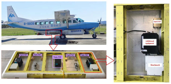
Figure 3.
The flight experimental setup.
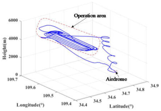
Figure 4.
The whole flight experiment process.
In actual flight, due to the limitation of the number of antennas, only the left node and the right node are equipped with dual antennas. For the convenience of description, the installation diagram of the array POS is simplified as Figure 5, and the following processing is illustrated with the left node and the right node. The data from a 2-min stable flight phase are selected for the semi physical simulation verification experiment. The simulation parameter settings of each sub-IMU are shown in Table 2.

Figure 5.
The installation diagram of array POS.

Table 2.
The simulation parameter settings of each sub-IMU.
4.2. Verification of Assessment and Correction Method for Abnormal Values of Measurement Information Based on Innovation
Military application is a potential application background for the array POS, where there are various types of deliberate jamming. However, the consequence of all types of deliberate jamming is that there are outliers in measurement data or in inertial device data. Referring to a large number of flight-test and vehicle-test data, we find that outliers mainly have two forms: isolated type and continuous type. Therefore, in this paper, discrete and continuous noises are superimposed on normal measurement data to simulate measurement data in a strong interference environment.
4.2.1. Simulation Condition and Initialization
Concerning the measurement information in the array POS, GNSS has long-term stability in accuracy and is used to correct the error accumulated by IMU over time. However, the measurement outliers may appear in some special cases, such as large maneuvers of the carrier, entering strong electromagnetic fields or areas with many clouds. Thus, to test the effectiveness of the proposed method when there are outliers in measurement information, GNSS data is superimposed with outliers.
As shown in Figure 6, the height, up-velocity and heading angle data output from dual antennas are superimposed with five isolated random outliers and five continuous outliers. The isolated random outliers are superimposed when time is 50 s and the continuous outliers are 75 s. The mean value of continuous outliers is 5, and the variance is 10, while the interval of the isolated outlier is 5 s. The processed data of GNSS in the left node and right node are shown in Figure 6a,b, respectively.
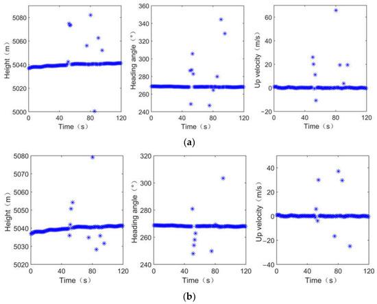
Figure 6.
Data from GNSS after adding outliers. (a) Data from GNSS in left node after adding outliers; (b) Data from GNSS in right node after adding outliers.
4.2.2. Simulation Results and Analysis
The comparison result between the proposed method and the traditional method of position, velocity and attitude are shown in Figure 7. It is noted that the traditional FKF in this section is the traditional federated Kalman filtering algorithm. Figure 7a shows the position errors. It can be seen in the figure that the maximum latitude error, longitude error and altitude error of the left node calculated by traditional KFK are 0.78 m, 1.19 m and −9.15 m, respectively, while those of the left node calculated by the proposed method are 0.23 m, 1.18 m, 1.21 m, respectively. The maximum latitude error, longitude error and altitude error of the right node calculated by traditional KFK are −0.56 m, 1.23 m and −17.76 m, respectively, while those of the right node calculated by the proposed method are 0.22 m, 1.23 m and 1.11 m, respectively. The latitude and height are both greatly improved by the proposed method in both the left node and the right node when there are abnormal values in the measurement information. In Figure 7b, the maximum north velocity errors of the left node and the right node calculated by traditional KFK are 1.40 m/s and 0.26 m/s, while those calculated by the proposed method are −1.39 m/s and −0.22 m/s, respectively. The maximum east velocity errors of the left node and the right node calculated by traditional KFK are 0.62 m/s and 0.57 m/s, while those calculated by the proposed method are −0.27 m/s and −0.16 m/s, respectively. The maximum up velocity errors of the left node and the right node calculated by traditional KFK are −4.98 m/s and −9.46 m/s, while those calculated by the proposed method are 0.32 m/s and −0.09 m/s, respectively. That is, the north velocity, east velocity and the up velocity of the left node and the right node all fluctuate greatly when outliers appear. In Figure 7c, the maximum heading angle errors of the left node and the right node calculated by traditional KFK are −2.61° and −2.65°, while those calculated by the proposed method are 0.26° and −0.37°, respectively. The maximum pitch angle errors of the left node and the right node calculated by traditional KFK are −0.96° and −1.23°, while those calculated by the proposed method are −0.32° and −0.25°, respectively. The maximum roll angle errors of the left node and the right node calculated by traditional KFK are −3.88° and 4.23°, while those calculated by the proposed method are −0.16° and −0.23°, respectively. Namely, all the attitude angles are affected by abnormal values, and the proposed method effectively eliminates the influence of abnormal values in both the left node and the right node.
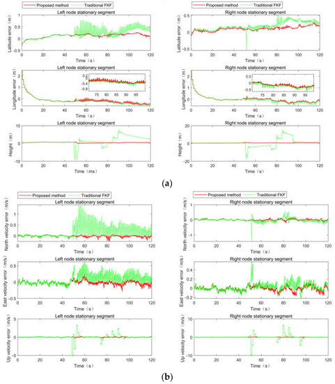
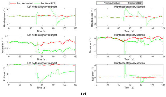
Figure 7.
Comparison of filtering results. (a) Position comparison of filtering results; (b) velocity comparison of filtering results; (c) attitude comparison of filtering results.
Standard deviation (STD) is adopted in this section to quantify the errors of the array POS calculated by the proposed method and the traditional FKF. Table 3 shows the accuracy of the left node and right node. The real-time combination accuracies of position, velocity, heading and pitch angle and roll angle of the left node and right node are both improved by the proposed method when there are abnormal values in the GPS data. The accuracies of position, speed, heading and pitch angle and roll angle of the left node are improved by 79.05%, 83.34%, 82.49%, 67.42% and 91.87%, respectively. The accuracies of position, speed, heading and pitch angle and roll angle of the right node are improved by 81.81%, 86.44%, 84.25%, 58.95% and 86.76%, respectively, which proves the effectiveness of the proposed method in this paper in the detection of abnormal values in measurement information.

Table 3.
STD accuracies of position, velocity and attitude.
4.3. Verification Assessment and Correction of Abnormal Values from Inertial Devices Based on Extrapolation Prediction
4.3.1. Simulation Condition and Initialization
The sub-IMUs with small volume, low cost and light weight, whose inertial device performance is relatively poor, are adopted in the array POS,. As a result, inertial device outliers may occur in a harsh flight environment or some strong interference environments. In this way, to verify the effectiveness of the proposed method, the data from the gyro and accelerometer in the x-axis direction are superimposed with five isolated outliers and five continuous outliers. The mean value of the continuous outliers is 5, and the variance is 10, while the interval of the isolated outlier is 5 s. The processed data from the gyro and accelerometer in the x-axis are shown in Figure 8a,b, respectively. It is noted that data in the stable flight phase are selected to count the measurement accuracy of the POS system. Since the attitude angle is small in the stable flight phase, the abnormal values added on the gyroscope and accelerometer in the x-axis direction only have a great impact on the position and speed in one direction, and the effect in other directions is not obvious, which does not affect the verification results.
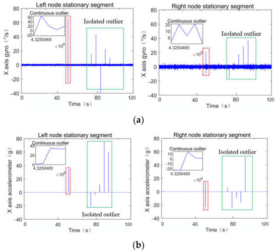
Figure 8.
Data from the IMU after adding outliers. (a) Data from the gyro in the x-axis direction after adding outliers; (b) data from the accelerometer in the x-axis direction after adding outliers.
4.3.2. Simulation Results and Analysis
The comparison result between the proposed method and the traditional method of position, velocity and attitude are shown in Figure 9. It is noted that the traditional method in this section is the fault-tolerant federated combination method based on innovation characteristics. In Figure 9a, the maximum latitude error, longitude error and altitude error of the left node calculated by the traditional method are −12.91 m, 1.22 m and 0.89 m, respectively, while those calculated by the proposed method are 3.62 m, 1.21 m and 0.89 m, respectively. The maximum latitude error, longitude error and altitude error of the right node calculated by the traditional method are −14.08 m, 1.26 m and 0.81 m, respectively, while those calculated by the proposed method are 1.16 m, 1.26 m and 0.79 m, respectively. The latitude is most affected by abnormal values, and the accuracy is greatly improved by the proposed method in both the left node and the right node, which matches the previous analysis. In Figure 9b, the maximum north velocity error, east velocity error and up velocity error of the left node calculated by the traditional method are −5.20 m/s, 0.22 m/s and 0.28 m/s, respectively, while those calculated by the proposed method are 0.12 m/s, 0.22 m and 0.28 m, respectively. The maximum north velocity error, east velocity error and up velocity error of the right node calculated by the traditional method are −5.18 m/s, −0.27 m/s and −0.18 m/s, respectively, while those calculated by the proposed method are 0.10 m/s, 0.13 m and −0.18 m, respectively. The north velocity of the left node and the right node fluctuate greatly, and the east and up velocity are relatively stable when an abnormal value appears, which also matches the previous analysis. In Figure 9c, the maximum heading angle error of the left node and the right node calculated by the traditional method are −0.26° and −0.38°, and those calculated by the proposed method are also −0.26° and −0.38°, respectively. The maximum pitch angle error of the left node and the right node calculated by the traditional method are −0.82° and −0.93°, and those calculated by the proposed method are 0.81° and −0.81°, respectively. The maximum roll angle error of the left node and the right node calculated by the traditional method are −0.77° and −0.99°, and those calculated by the proposed method are 0.14° and −0.15°, respectively. Compared with heading and pitch angle, roll angle is more affected by abnormal values, and the proposed method effectively eliminates the influence of abnormal values both in the left node and the right node.
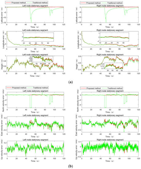
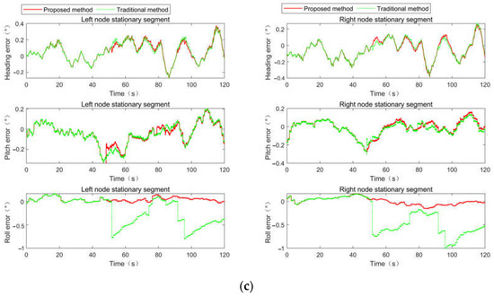
Figure 9.
Comparison of filtering results. (a) Position comparison of filtering results; (b) velocity comparison of filtering results; (c) attitude comparison of filtering results.
Table 4 shows the accuracy of the left node and right node. STD is also selected as the error statistics method in this section. The real-time combination accuracies of position, velocity, heading and pitch angle and roll angle of the left node and right node are both improved by the proposed method when there are abnormal values in MIMU. The accuracies of position, speed, heading and pitch angle and roll angle of the left node are improved by 78.57%, 84.86%, 0.17%, 7.38% and 83.23%, respectively. The accuracies of position, speed, heading and pitch angle and roll angle of the right node are improved by 80.47%, 87.80%, 1.43%, 8.89% and 78.30%, respectively, which proves the effectiveness of the proposed method in this paper in the detection of abnormal values in inertial devices.

Table 4.
STD accuracy of position, velocity and attitude.
5. Conclusions
The inertial devices and measurement systems of the array POS are vulnerable to a strong interference environment, which leads to the decline or even divergence in the accuracy of their combined results. An improved innovation robust outlier detection method is proposed to solve this problem in this paper. On the filter structure, the isolated and continuous outliers of device level and system level are detected and corrected, respectively. The effectiveness of this method is verified by a semi-physical simulation experiment based on an actual flight experiment. The results indicate that the accuracies of position, speed, heading and pitch angle and roll angle of the left node are improved by 79.05%, 83.34%, 82.49%, 67.42% and 91.87%, respectively. The accuracies of position, speed, heading and pitch angle and roll angle of the right node are improved by 81.81%, 86.44%, 84.25%, 58.95% and 86.76%, respectively, when there are abnormal values in the measurement data. Furthermore, the accuracies of position, speed, heading and pitch angle and roll angle of the left node are improved by 78.57%, 84.86%, 0.17%, 7.38% and 83.23%, respectively. The accuracies of position, speed, heading and pitch angle and roll angle of the right node are improved by 80.47%, 87.80%, 1.43%, 8.89% and 78.30%, respectively, when there are abnormal values in the inertial device data. The robustness of the array POS system is improved by the method in this paper, which has good application value in the project. The practical engineering application will be carried out in the future.
Author Contributions
Conceptualization, B.J. and L.J.; methodology, B.J.; software, B.J.; validation, B.J. and L.J.; formal analysis, B.J. and L.J.; investigation, L.J. and W.M.; resources, L.J.; data curation, L.J.; writing—original draft preparation, B.J.; writing—review and editing, B.J., L.J. and Q.C.; visualization, B.J., L.J., Q.C. and W.M.; supervision, L.J.; project administration, L.J.; funding acquisition, L.J. All authors have read and agreed to the published version of the manuscript.
Funding
This research was funded by the National Natural Science Foundation of China under Grant 61722103, Grant 62173019, Grant 61973020 and Grant 61873019 and, in part, by the Beijing Natural Science Foundation under Grant 4222047.
Data Availability Statement
Not applicable.
Conflicts of Interest
The authors declare no conflict of interest.
References
- Qu, C.; Li, J.; Bao, J.; Zhu, Z. Design and Development of Array POS for Airborne Remote Sensing Motion Compensation. Remote Sens. 2022, 14, 3420. [Google Scholar] [CrossRef]
- Qu, C.; Li, J. A novel relative motion measurement method based on distributed POS relative parameters matching transfer alignment. Measurement 2022, 202, 111890. [Google Scholar] [CrossRef]
- Wang, B.; Ye, W.; Liu, Y. Enhanced Disturbance Suppression Method Based on Nonlinear H∞ Filtering for Distributed POS in Aerial Earth Observation Imaging Application. IEEE Trans. Geosci. Remote Sens. 2022, 60, 5211509. [Google Scholar] [CrossRef]
- Wang, B.; Ye, W.; Liu, Y. Variational Bayesian cubature RTS smoothing for transfer alignment of DPOS. IEEE Sens. J. 2020, 20, 3270–3279. [Google Scholar] [CrossRef]
- Gautam, D.; Lucieer, A.; Malenovský, Z.; Watson, C. Comparison of MEMS-Based and FOG-Based IMUs to Determine Sensor Pose on an Unmanned Aircraft System. J. Surv. Eng. 2017, 143, 04017009. [Google Scholar] [CrossRef]
- Cai, T.; Xu, Q.; Zhou, D.; Gao, S.; Liu, Y.; Huang, J.; Emelyantsev, G.I.; Stepanov, A.P. A Multimode GNSS/MIMU Integrated Orientation and Navigation System. In Proceedings of the 2019 26th Saint Petersburg International Conference on Integrated Navigation Systems (ICINS), St. Petersburg, Russia, 27–29 May 2019. [Google Scholar]
- Lu, H.; Zhang, H.; Fan, H.; Liu, D.; Wang, J.; Wan, X.; Zhao, L.; Deng, Y.; Zhao, F.; Wang, R. Forest Height Retrieval Using P-band Airborne Multibaseline SAR Data: A Novel Phase Compensation Method. ISPRS J. Photogramm. Remote Sens. 2021, 175, 99–118. [Google Scholar] [CrossRef]
- Mahmoud, R.; Ahmed, E.R. Integration of Multi-Constellation GNSS Precise Point Positioning and MEMS-Based Inertial Systems Using Tightly Coupled Mechanization. Positioning 2015, 6, 81–95. [Google Scholar]
- Zhou, Q.; Zheng, L.; Yu, G.; Li, H.; Zhang, N. A Novel Adaptive Kalman Filter for Euler Angle Based MEMS IMU/ Magnetometer Attitude Estimation. Meas. Sci. Technol. 2020, 32, 045104. [Google Scholar] [CrossRef]
- Wang, Q.; Cui, X.; Li, Y.; Ye, F. Performance Enhancement of a USV INS/CNS/DVL Integration Navigation System Based on an Adaptive Information Sharing Factor Federated Filter. Sensors 2017, 17, 239. [Google Scholar] [CrossRef] [PubMed]
- Li, Z.; Liu, Z.; Zhao, L. Improved robust Kalman filter for state model errors in GNSS-PPP/MEMS-IMU double state integrated navigation. Adv. Space Res. 2021, 67, 3157–3168. [Google Scholar] [CrossRef]
- Xiao, X.; Liu, J. Adaptive Fault-tolerant Federated Filter with Fault Detection Method Based on Combination of LSTM and Chi-square Test. In Proceedings of the 40th Chinese Control Conference, Shanghai, China, 26–28 July 2021; pp. 3059–3064. [Google Scholar]
- Zhang, H.; Dong, L.; Zhang, G. Application of hybrid chi-square test method in fault detection of integrated navigation system. J. Chin. Inert. Technol. 2016, 24, 696–700. [Google Scholar]
- Li, S.; Zhang, M.; Ji, Y.; Zhang, Z.; Cao, R.; Chen, B.; Li, H.; Yin, Y. Agricultural Machinery GNSS/IMU Integrated Navigation Based on Fuzzy Adaptive Finite Impulse Response Kalman Filtering Algorithm. Comput. Electron. Agric. 2021, 191, 106524. [Google Scholar] [CrossRef]
- Hu, X.; Wang, Z. A New Method Based on Dual-State Chi-Square Fault-Tolerant to Inertial/Acoustic Range Integrated Navigation System with Single Transponder. In Proceedings of the 2019 26th Saint Petersburg International Conference on Integrated Navigation Systems (ICINS), St. Petersburg, Russia, 27–29 May 2019. [Google Scholar]
- Zhang, C.; Zhao, X.; Pang, C.; Zhang, L.; Feng, B. The Influence of Satellite Configuration and Fault Duration Time on the Performance of Fault Detection in GNSS/INS Integration. Sensors 2019, 19, 2147. [Google Scholar] [CrossRef] [PubMed]
- Xiong, L.; Xia, X.; Lu, Y.; Liu, W.; Gao, L.; Song, S.; Yu, Z. IMU-based Automated Vehicle Body Sideslip Angle and Attitude Estimation Aided by GNSS using Parallel Adaptive Kalman Filters. IEEE Trans. Veh. Technol. 2020, 69, 10668–10680. [Google Scholar] [CrossRef]
- Cong, N.; Wang, W.; Zhu, Z. Design of improved fault-tolerant filtering algorithm based on multi-source information fusion. In Proceedings of the 2020 Chinese Automation Congress (CAC), Shanghai, China, 6–8 November 2020; pp. 918–923. [Google Scholar]
- Zhang, H.; Xiao, Y.; Yang, C.X. Integrated navigation system based on fauIt detection using double state Chi-square test. Acta Aeronaut. Astronaut. Sin. 2020, 41 (Suppl. S2), 724271. [Google Scholar]
- Gong, X.L.; Ding, X.S. Adaptive CDKF Based on Gradient Descent with Momentum and its Application to POS. IEEE Sens. J. 2021, 21, 16201–16212. [Google Scholar] [CrossRef]
- Liang, X.; Bo, Y.; Yang, X.; Yuan, D.; Wang, X.; Chang, H. A Redundant Fused MIMU Attitude System Algorithm Based on Two-stage Data Fusion of MEMS Gyro Clusters Array. Measurement 2021, 184, 109993. [Google Scholar]
- Ye, W.; Liu, Z.; Li, C.; Fang, J. Enhanced Kalman Filter using Noisy Input Gaussian Process Regression for Bridging GNSS Outages in a POS. J. Navig. 2018, 71, 565–584. [Google Scholar] [CrossRef]
- He, Y.J.; Lu, X.D.; Lv, C.H. Calculation and correction method for MEMS strap-down Inertial Navigation System. Comput. Meas. Control 2010, 18, 1364–1366. [Google Scholar]
- Ren, C.; Liu, Q.; Fu, T. A Novel Self-Calibration Method for MIMU. IEEE Sens. J. 2015, 15, 5416–5422. [Google Scholar] [CrossRef]
Disclaimer/Publisher’s Note: The statements, opinions and data contained in all publications are solely those of the individual author(s) and contributor(s) and not of MDPI and/or the editor(s). MDPI and/or the editor(s) disclaim responsibility for any injury to people or property resulting from any ideas, methods, instructions or products referred to in the content. |
© 2022 by the authors. Licensee MDPI, Basel, Switzerland. This article is an open access article distributed under the terms and conditions of the Creative Commons Attribution (CC BY) license (https://creativecommons.org/licenses/by/4.0/).