Article

Study of Coastal Effects Relevant for Offshore Wind Energy Using Spaceborne Synthetic Aperture Radar (SAR)

by
Bughsin’ Djath
1,*,
Johannes Schulz-Stellenfleth
1 and
Beatriz Cañadillas
2,3
1
Institute of Coastal Systems-Analysis and Modeling, Helmholtz-Zentrum Hereon, 21502 Geesthacht, Germany
2
UL International GmbH, 26122 Oldenburg, Germany
3
Institute of Flight Guidance, Technische Universität Braunschweig, 38108 Braunschweig, Germany
*
Author to whom correspondence should be addressed.
Remote Sens. 2022, 14(7), 1688; https://doi.org/10.3390/rs14071688
Submission received: 2 March 2022 / Revised: 25 March 2022 / Accepted: 28 March 2022 / Published: 31 March 2022

Abstract

:
Coastal wind speed gradients relevant for offshore windfarming are analysed based on synthetic aperture radar (SAR) data. The study concentrates on situations with offshore wind directions in the German Bight using SAR scenes from the European satellites Sentinel-1A and Sentinel-1B. High resolution wind fields at 10 m height are derived from the satellite data set and respective horizontal wind speed gradients are investigated up to about 170 km offshore. The wind speed gradients are classified according to their general shape with about 60% of the cases showing an overall increase of wind speeds with growing distance from the coast. About half of the remaining cases show an overall wind speed decrease and the other half a decrease with a subsequent increase at larger distances from the coast. An empirical model is fitted to the horizontal wind speed gradients, which has three main parameters, namely, the wind speed over land, the equilibrium wind speed over sea far offshore, and a characteristic adjustment length scale. For the cases with overall wind speed increase, a mean absolute difference of about 2.6 m/s is found between wind speeds over land and wind speeds far offshore. The mean normalised wind speed increase with respect to the land conditions is estimated as 40%. In terms of wind power density at 10 m height this corresponds to an absolute average growth by 0.3 kW/m2 and a normalised increase by 160%. The distance over which the wind speed grows to 95% of the maximum wind speed shows large variations with maximum above 170 km and a mean of 67 km. The impact of the atmospheric boundary layer stability on horizontal wind speed gradients is investigated using additional information on air and sea temperature differences. The absolute SAR-derived wind speed increase offshore is usually higher in unstable situations and the respective adjustment distance is shorter. Furthermore, we have found atypical cases with a wind speed decrease offshore to be often connected to stable atmospheric conditions. A particular low-level jet (LLJ) situation is analysed in more detail using vertical wind speed profiles from a wind LIDAR system.

1. Introduction

Offshore windfarming has become a rapidly expanding component in the global energy sector. In Germany, about 1500 turbines with 7.8 MW capacity were installed in coastal waters by 2020 and a further growth to 30 GW is planned until 2030 [1]. On a global scale, the offshore wind power capacity grew from 3 GW in 2010 to 23 GW in 2018 [2] and has now reached 35 GW [3]. For two main reasons this technology has become an attractive option. Firstly, wind speeds above water are usually significantly higher than above land. Secondly, the airflow over water is usually less turbulent than over land. As the installation costs grow with water depth and the costs for the integration into the electrical grid grow with distance from land, most offshore windfarms (OWFs) are still built in relative proximity (about 100 km) to the shoreline [4].
The higher wind power available offshore is caused by differences of mechanical and thermodynamic properties of the ocean and the land. Over a big patch of homogeneous ocean or land surface one can usually find an atmospheric boundary layer, which is in an approximate equilibrium with respect to pressure gradients, frictional forces and the Coriolis force. However, in coastal areas, where most of the existing offshore wind farms are located, a complex transition process occurs between the land and the ocean boundary layer. This phenomenon is of particular interest for offshore wind directions, where an internal boundary layer (IBL) forms downstream of the land boundary. The three-dimensional (3D) dynamics of the atmosphere in this transition zone is complicated and constitutes a challenge for numerical forecasting for different reasons. Firstly, there is usually insufficient information about roughness properties of the land surface, and the sea surface roughness is affected by ocean surface waves, which have a complex dynamics by themselves. Secondly, the formation of the IBL is strongly conditioned by the 3D dynamics of turbulence (e.g., horizontal advection), which is still a challenge for atmospheric models as well. Thirdly, the stability of the boundary layer is affected by the sea surface temperature in the transition region. These temperatures often show horizontal gradients related to changes in water depths, which are still difficult to capture accurately by either satellites or numerical ocean models.
As the representation of coastal effects in numerical models is still challenging, measurements are important to improve the understanding and the prediction of the respective processes [5,6]. The importance of thermal effects and sea surface roughness was investigated in a number of previous studies [7,8,9]. The role of advection processes in the land-sea transition region and their relevance for offshore wind farms was discussed in Dörenkämper et al. [10]. Large Eddy Simulations (LES) were used in Dörenkämper et al. [11] to study the dependence of wind power available to a wind farm on the distance from the shoreline.
In this study, satellite synthetic aperture radar (SAR) data are used to analyse coastal effects and the potential impacts on offshore wind farms are briefly discussed. SAR data provide information on near surface wind speeds over the ocean with high spatial resolution (e.g., 400 m) and are independent of cloud or daylight conditions [12,13]. These data are therefore well suited to study the spatial evolution of the wind field from land towards the sea under different atmospheric conditions. SAR data have already been used in the offshore wind context in several previous studies [13,14,15,16,17,18]. Barthelmie et al. [19] looked at coastal wind speed gradients at the Danish coast with SAR as well, although the focus of their study was on in-situ and model data analysis. More detailed discussions of shapes of horizontal wind speed gradients or dependencies on stability of the boundary layer were not given.
The main objective of this study is to analyse the shape of the horizontal wind speed gradients derived from SAR datasets and the respective dependence on the stability of the atmospheric boundary layer in OWF areas. Furthermore, the goal is to condense the SAR information into an empirical model for the coastal effect, which can be used as a reference in subsequent studies.
The study is focused on the German Bight, which is a particularly interesting region to study coastal effects, because the mirrored L-shaped form of the coastline leads to offshore wind directions for both easterly and southerly winds. A characteristic of the German Bight is the very shallow water depth with a maximum of about 50 m and Wadden Sea areas, which are periodically falling dry following the dominant M2 tidal component with 12.42 h period [20,21]. Also, the shape of the coastline is complicated by the east Frisian and north Frisian barrier islands, as well as various bays. Temperature differences between the water and the air advected from land are important factors for the stability of the boundary layer and can have impacts on coastal effects as well. Sea surface temperature variations related to variable water depths are an additional complicating factor.
The paper is structured as follows: In Section 2, data and methods are described. In particular, general theoretical aspects of coastal effects are introduced. The analysis of horizontal wind speed gradients and the stability dependence are presented in Section 3. The discussion is presented in Section 4. Finally the summary and the outlook are given in Section 5.

2. Data and Methods

The primary data sets used for the analysis in this study are based on the wind speed derived from SAR. Auxiliary data sets and the applied methods are introduced in this section.

2.1. Synthetic Aperture Radar (SAR) Derived Wind Field

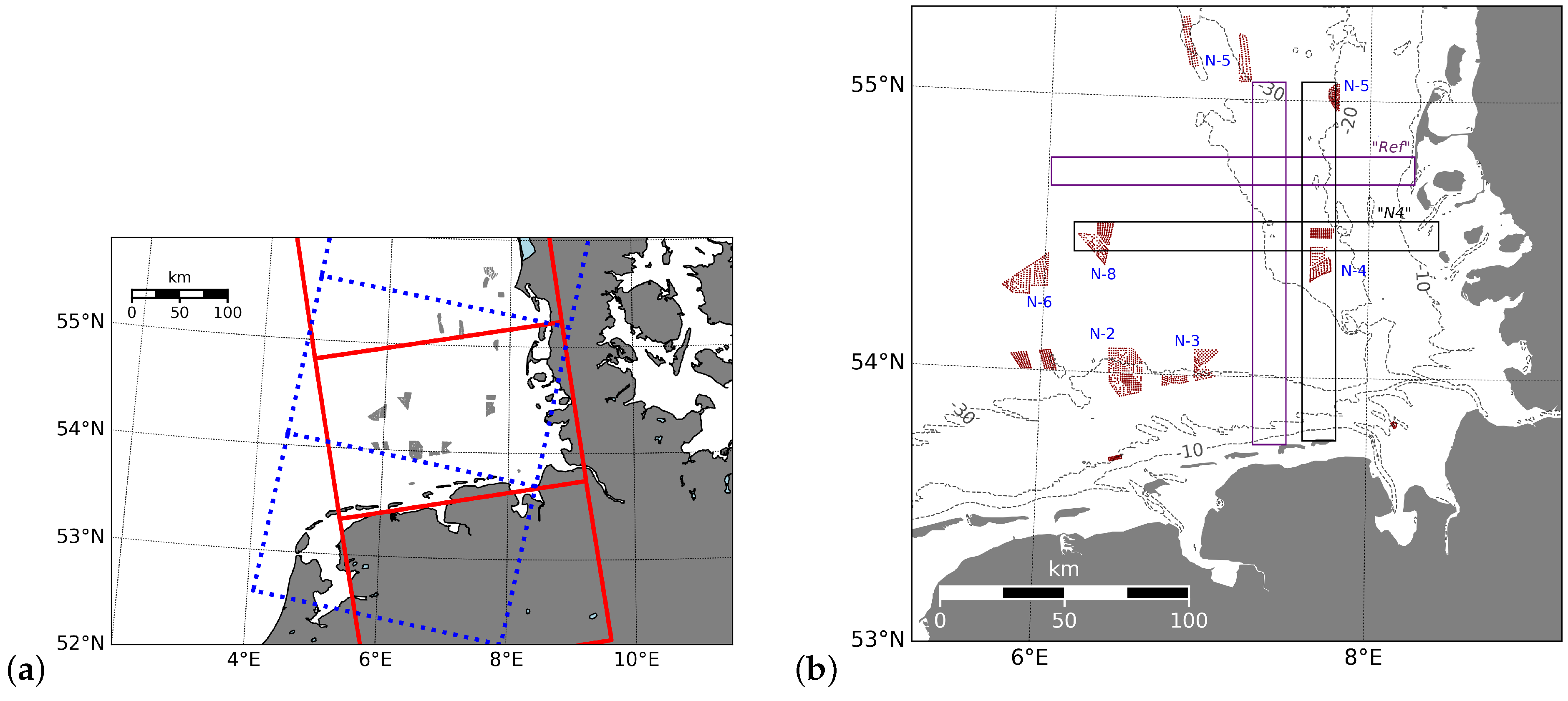
The analysis of the horizontal wind speed profiles is based on C-band SAR data from the satellites Sentinel-1A and Sentinel-1B, which are operated in the framework of the Copernicus program [22,23]. The Sentinel-1A/B overflights over the German Bight (Figure 1) are around 5UTC for descending or 17UTC for ascending orbits (Figure 2a). With both satellites each location is sampled with identical imaging geometry every 6 days. The investigation of horizontal wind speed maps from SAR is performed from January 2017 to December 2020 and focused on the imaging geometries that cover almost the entire German Bight and totally encompass the transects considered for the study (see Section 2.3 and Figure 2b). This leads to 244 and 243 SAR scenes for morning and evening overflights, respectively.
The conversion of the SAR radar cross section into 10 m wind speed is traditionally performed through geophysical model functions (GMFs). There are two main approaches for the SAR wind speed retrieval. In the first approach, the GMF relates the calibrated normalized radar cross section (NRCS) to the wind speed, the wind direction and a radar incidence angle typically between 20 and 45 . The wind direction is yet unknown, but can be obtained either from streak-like features on the SAR image [25,26], or provided by an external data source (e.g., meteorological datasets). A limitation of this approach is uncertainties in the wind direction. The determination of the wind direction through an NRCS image can be challenging, as there is no guarantee of having visible streak-like features. Furthermore, this procedure often contains some 180 ambiguity. However, an external source of wind direction has often a coarser resolution, which means that wind direction variability at smaller scales is potentially neglected. Nonetheless, the use of external wind direction usually works well where wind direction gradients are smooth. In the second approach, wind speed can be retrieved directly from SAR image without any wind direction information [27,28,29]. For instance, in Kerbaol et al. [28], the SAR wind algorithm is based on the smearing of the SAR image in flight direction (azimuth) caused by the orbital motion of the sea surface. However, in coastal and nearshore areas, this technique has limitations as the shoaling and refraction of ocean waves can modulate the radar backscatter caused by local winds [30]. In addition, this approach underestimates wind speeds in situations of offshore winds, as the fetch and depth-limited waters affect the growth of the wave spectrum [31]. Since this study focuses on the variability of offshore winds, the second approach for wind retrieval was not used for the analysis presented here. Hourly wind data from the model run by the German Weather Service (DWD) are used to provide directional information for the first approach (see Section 2.5.2) to avoid any ambiguities and for consistency. The raw satellite signal is calibrated using the SNAP software tool [32]. To eliminate the effect of speckle noise from the radar signal, the retrieved wind speed is smoothed down to a resolution of 400 m. This procedure is a reasonable compromise between noise reduction and the preservation of a high spatial resolution of the retrieved wind field. The GMF used for the derivation of wind speed from SAR in this study is CMOD5.N [33], which is tuned for winds speeds at neutral conditions. The detailed procedures regarding the 10 m wind retrieval are given in Djath et al. [17] and Djath et al. [13].
The use of CMOD5.N for the SAR wind speed retrieval introduces some errors for the cases, where the boundary layer is not neutral. It was shown in Hasager et al. [15] that the standard deviation of the derived SAR wind speed in comparison to in-situ measurements is about 1.9 m/s. It is important to emphasize in this context that the present study is mainly concerned with relative changes of wind speeds, i.e., changes with respect to the wind speed over land. In a first approximation, the wind speed profile over the ocean can be modelled as
u ( z ) = Φ ( z , u * , L ) = u * κ log ( z z 0 ) Ψ ( z / L ) ,
where u * is the friction velocity, κ is the Karman constant, z 0 is the ocean surface roughness length and L is the Obukhov length. The stability function Ψ has different forms for stable and unstable conditions and the version used here can be found in Leelössy et al. [34]. An approximation of the roughness length z 0 can be derived from the friction velocity using the Charnock relation [34]. For a given incidence angle and wind direction, the observed radar cross section is mainly determined by u * , i.e., the wind speed at 10 m height derived from CMOD5.N can be written as
U 10 = Φ ( z = 10 m , u * , L = )
which is Equation (1) evaluated for neutral conditions and z = 10 m. We now analyse the error in the estimation of the relative wind speed increase for the case that the boundary is not neutral, i.e., L = L < . Let us denote the saturated friction velocity far offshore as u O S * . We know from our statistical analysis presented in Section 3.5, that the relative wind speed increase with respect to land conditions is typically about 40%; the friction velocity close to the land is therefore of the order of u l a n d * = u O S * /1.4. The correction factor that needs to be applied to derive the “true” U 10 wind speed from the CMOD5.N estimate is Φ ( u * , L = L ) / Φ ( u * , L = ) . The correction factor C for the ratio of offshore wind speed and land wind speed is
C ( L , u O S * ) = Φ ( u O S * , L = L ) Φ ( u l a n d * , L = ) Φ ( u O S * , L = ) Φ ( u l a n d * , L = L ) .
This function was evaluated for friction velocities u O S * [ 0.1   m / s , 1   m / s ] and for L [ 8   m , 1000   m ] (representing stable to neutral conditions) and L [ 1000   m , 2   m ] (representing neutral to unstable conditions). The derived range for the ratio was C [ 0.979 , 1.000 ] for unstable conditions and C [ 1.000 , 1.030 ] for stable conditions. This means that the percentage error for the relative wind speed increase due to the use of CMOD5.N in non-neutral conditions is 3% at most, which is regarded as negligible for the presented analysis.

2.2. Theoretical Background of Coastal Effects

Typically, wind speeds increase with growing distance from the coast in situations where the wind is blowing from land to sea. The primary reason for this effect is that the land surface roughness is about two orders of magnitude higher than the roughness of the sea surface. The frictional forces are therefore reduced and the air in the boundary layer is accelerated. At the same time a transformation takes place between the boundary layers over land and the ocean, respectively. In the transition zone a so called IBL forms, which can extend to more than 100 km offshore until a balanced marine boundary layer is established. Details of this transition process depend not only on the ratio of the land and sea roughness length scales m = z l a n d / z o c e a n , but also on the stability of the boundary layer. In general, the boundary layer adjustment process is taking place over shorter length scales in unstable conditions.
To illustrate these effects a simple atmospheric model as described in Taylor [9] can be used. The model describes the airflow over a step discontinuity of surface roughness. In the following we will denote the roughness lengths of the land and the ocean by z l a n d and z s e a , respectively. The 2D model is based on the numerical solution of the momentum equation
U U x + W U z = τ z
and the continuity equation
U x + W z = 0
with the shear stress given by
τ = κ 2 ( z + z s e a ) 2 ( U x ) 2 ,
where κ is the von Karman constant. The horizontal wind speed component in x direction is denoted by U and the vertical component in z direction is represented by W. Equation (6) corresponds to neutral conditions and is generalised in this study using a respective stability function Φ according to
τ = κ 2 1 Φ 2 ( z / L ) ( z + z s e a ) 2 ( U x ) 2
with Obhukov length L. A similar approach was utilised in Taylor [8], where an additional prognostic equation for temperature was used. Following previous studies [35], the stability function was formulated for stable conditions (L > 0) as
Φ ( z / L ) = 1 + 5 z / L
and for unstable conditions (L < 0) as
Φ ( z / L ) = ( 1 16 z / L ) 1 / 4 .
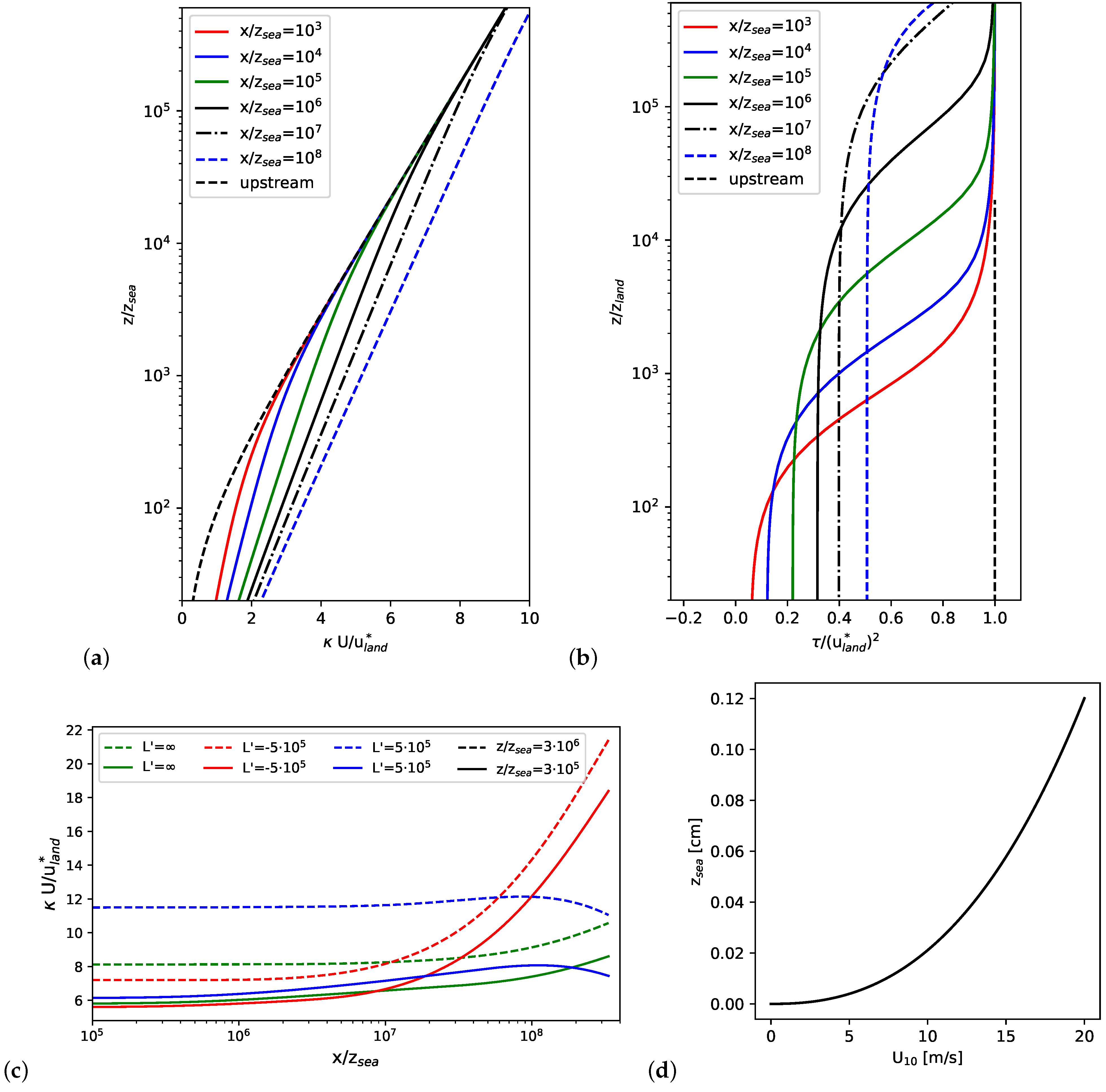
More details about the numerical treatment used to solve the equations above can be found in Taylor [9]. Figure 3 shows a simulation of vertical profiles of normalised wind speeds (a) and normalised stresses (b) for neutral conditions (L = ) and a roughness ratio m = 55 . These are extended versions of plots, which can be found in Taylor [9]. The black dashed line corresponds to the upstream horizontal wind speed profile over land. One can see that the highest wind speed increases near the coast are found in the lower levels and growing wind speeds at higher levels are found further offshore. The friction velocity, which is the square root of the normalised horizontal stress, shows a strong drop near the coast and then slowly recovers to higher values. As the model assumes identical momentum fluxes into the boundary layer over land and ocean from above, the friction velocity profile that eventually forms far offshore is the same as over land (dashed black lines). The order of magnitude for sea surface roughness lengths can be seen in Figure 3d, where z s e a is plotted as a function of wind speed at 10 m height making the simplifying assumption that the sea state is fully developed [36]. Assuming that the roughness length z s e a is 0.1 cm, the blue dashed curves in Figure 3a,b correspond to a distance of about 10 km to land and the boundary layer is obviously still far from an equilibrium at that stage.
In Figure 3c, horizontal wind speed profiles of wind speeds are plotted at two normalised heights. The profiles in green, blue and red, respectively, refer to neutral, stable and unstable boundary layers. The curves are obtained using different values for the normalised Obhukov length L’ = L/ z s e a in combination with the stability functions in Equations (8) and (9). One can see that the acceleration effect is strongest in unstable conditions. It is also interesting to see that for stable conditions, the wind speed starts to drop at a certain land distance after reaching a maximum. These simulations are supposed to give a very simplifying qualitative impression about the basic mechanisms and are not perfectly expected to match observations.
An important conclusion from the study presented in Taylor [9] is that under certain simplifying assumptions, the downstream wind speed profiles scale with the upstream wind speed and also with the equilibrium wind speed that is finally obtained far offshore. This means that it makes sense to look at relative wind speed changes in relation to the land or ocean conditions. In the following analysis of SAR-derived wind speed transects, we will make use of this property.

2.3. Downwind Horizontal Wind Speed Gradient Estimations

In this study, surface wind fields derived from SAR data (Section 2.1) with a particular focus on offshore wind directions, i.e., winds blowing from land towards the sea, are analysed. For the land boundaries of the German Bight, offshore winds can be found for a wide wind direction sector of more than 90 from northeast to southwest (see Figure 1 and Figure 4). Atmospheric wakes downstream of wind farms in the German Bight (see Figure 1 and Figure 2b) are superimposed on coastal effects especially for southwesterly wind directions. Cluster N-4 (Figure 1) is relatively isolated from neighbouring wind farms and the surrounding area was therefore chosen to analyse coastal effects with and without wake interaction. The investigation of the horizontal wind gradient focuses on southerly and easterly wind directions. The geometric structures of the southern and eastern coastlines of the German Bight are different. For the eastern coastline the barrier islands are distributed over a larger area and the coastline therefore has a more fuzzy appearance. As we suspected that these differences have an impact on the boundary layer transition process, both wind directions were analysed separately (Figure 2b). More precisely, we consider easterly and southerly winds with wind directions ranging, respectively, from 60 to 120 and from 160 to 200 (see Table 1) to increase the probability to collect SAR wind field acquisitions with respect to offshore winds for more robust statistics.
To closely follow the evolution of the offshore winds with growing distance from the shore, two transects are defined parallel to the wind direction coming from the land: (1) One transect (named “Ref”) is considered in the area that is free of wind farms in order to minimise their effects on the horizontal wind speed profiles (Figure 2b); (2) A second transect is placed in such a way that it crosses the wind farms (e.g., cluster N-4 for easterly and southerly wind) to analyse potential interactions of coastal effects with the atmospheric wakes. This transect is hereafter named “ N 4 ” as it crosses the cluster N-4. The width of the transects are chosen to be 13 km, which is wide enough to represent the large-scale variability. Furthermore, the width of the transects is large enough to include wake effects, as the length scale of most wind farms in the German Bight is of the order of 10 km. It is well known that SAR data in very shallow water can be affected by oceanic effects, which are not related to surface wind speeds [37]. As the water depths in the German Bight close to land is in fact small for the most part (see Figure 1 and Figure 2b), the start point of the transects on the land side is defined as the 10 m water depth isobath. The bathymetry effects on the surface roughness and the retrieved wind speed as reported in Horn Rev by Christiansen and Hasager [38] are negligible around the cluster N-4 and do not impact the results. The elongated transects are subdivided into 2 km bins, which leads to boxes of 2 km × 13 km each. The wind speed is therefore spatially averaged over each 26 km 2 . This finally leads to one-dimensional horizontal SAR wind speed transect of u 10 that depends on the distance from the shore.
In the following three types of horizontal wind speed gradients will be considered using different types of normalisation and scaling of the wind speed:
  • the absolute wind speed u 10 ( x ) ,
  • the wind speed increase δ u 10 ( x ) = u 10 ( x ) u l a n d ,
  • the normalised wind speed increase R u 10 ( x ) = δ u 10 ( x ) / u l a n d .
Here, u 10 ( x ) is the horizontal wind speed derived from SAR at 10 m, u l a n d is the wind speed over land, u o f f s h o r e is the equilibrium wind speed that is obtained at some distance from the shoreline, and the coordinate x corresponds to the distance from the coast with respect to wind direction. As SAR is not able to provide wind information over land, it is clear that estimates of u l a n d can only be approximations based on measurements over areas covered by the sea that are very close to the land boundary. In the next section a method is presented to estimate both u l a n d and u o f f s h o r e as part of a one-dimensional fitting procedure.

2.4. Empirical Model for Horizontal Wind Speed Gradients

In order to condense the information retrieved from SAR into a few parameters, an empirical model is used to describe the one-dimensional downstream horizontal wind speeds from the coastline towards the sea, assuming that the horizontal wind speed gradients have a exponential behavior. With the coordinate x defined as before, the model can be written as
u f ( x ) = u l a n d   +   u o f f s h o r e u l a n d 1 exp ( x σ ) .
The parameter σ describes the distance at which about 63% of the final wind speed increase
Δ u = u o f f s h o r e u l a n d
is observed. In addition, the distance x 95 % will be considered, at which the wind speed has increased to 95% of its final value u o f f s h o r e . This distance can be expressed as
x 95 % = σ log 0.05 u o f f s h o r e Δ u .
The model given by Equation (10) is fitted to observed wind speed gradients using a least-squares approach, i.e., the following cost function is minimised
J ( σ , Δ u , u l a n d ) = i = 1 N ( u f ( x i ) u S A R ( x i ) ) 2 ,
where u S A R denotes the SAR wind measurements and the profile is sampled on N discrete points x 1 , , x N . A binsize of about 2 km was used for the subsequent analysis and the number of bins is around N = 60 . The nonlinear minimisation problem defined by Equation (13) was solved using a Gauss–Newton iteration method to obtain estimates for the parameters σ , Δ u , u l a n d and hence also u o f f s h o r e as well as x 95 % . From Equation (10), the modelled wind speed increase δ u f and the normalised wind speed increase R f can be derived as follows:
δ u f ( x ) =   u o f f s h o r e u l a n d 1 exp ( x σ )
and
R f ( x ) =   u o f f s h o r e u l a n d 1 1 exp ( x σ ) .
Given Equation (15) the expected maximum of the normalised wind speed increase R m a x f can be expressed as
R m a x f = R f ( x = ) =   u o f f s h o r e u l a n d / u l a n d .
Denoting the number of available SAR wind speed transects u 10 ( x ) by N p and the i t h transect by u 10 ( i ) ( x ) , the mean normalised wind speed increase R u 10 ( x ) is estimated as follows:
R u 10 ( x ) = 100 % × 1 N p i = 1 N p u 10 ( i ) ( x ) 1 N p i = 1 N p u l a n d ( i ) 1 N p i = 1 N p u l a n d ( i ) .
Downstream the coast the power density (power per rotor disc area) associated to the wind speed gradient from SAR measurements can also be computed using u f (Equation (10)) as:
ψ ( x ) = 1 2 ρ η ( u f ( x ) ) 3 ,
where ρ = 1.225 kg/m2 is the density of air and η the power coefficient (here η is taken as 0.4). In offshore, the average power density ψ is therefore expressed knowing the estimates of u o f f s h o r e as:
ψ o f f s h o r e = 1 2 ρ η 1 N p i = 1 N P ( u o f f s h o r e ( i ) ) 3 .
Scaling Equation (18) with the u l a n d in a similar way as in Section 2.3 and Equation (15), the average normalised power density transect R ψ ( x ) is computed as follow:
R ψ ( x ) = 100 % × 1 N p i = 1 N p u ( i ) f ( x ) 3 1 N p i = 1 N p ( u l a n d ( i ) ) 3 1 N p i = 1 N p ( u l a n d ( i ) ) 3 .

2.5. Auxiliary Data Sets

2.5.1. LIDAR Wind Profile

Wind LIDAR (Light Detection And Ranging) [39] is an optical remote sensing system to measure wind speed and direction as well as aerosol distributions. For that purpose, a pulsed light beam is emitted from a ground station into the atmosphere and is then reflected by aerosols. While the distance to an aerosol is determined by the time the light takes to travel to the target and back to the emitter, the velocity measurement relies on the Doppler shift of the optical wave. Knowing the frequency shift along three different coordinate axes it is possible to calculate the wind speed in each direction and subsequently the total wind speed vector. The main advantage of LIDAR compared to in-situ measurement techniques is the large vertical range. Measurements are—depending on weather conditions and device–feasible up to altitudes of several kilometers. Since the principle relies on optical measurements, a wind LIDAR does not work properly in clouds or foggy weather. Doppler LIDAR measurements are already well established in the wind energy research and their accuracy has been tested against met mast data up to 100 m above ground (offshore and onshore (at least over not too complex terrain)), (e.g., Courtney et al. [40], Canadillas et al. [41], Goit et al. [42]).
In this study, a so-called “WindCube” of type WLS8 vertical profiling, developed and manufactured by Leosphere (now Vaisala) and owned by the Institute of Flight Guidance at the Technical University (TU) Braunschweig [43], is used. The pulsed laser rotates in a coning pattern so that light is back-scattered by particles in the air and collected by the optical system. The acquisition of wind speeds in all three axial directions is accomplished by inclining the laser at 15 and measuring at azimuth intervals of 90 . This creates four distinctive measuring volumes. An electronic processing unit converts the signal and post-processes the data. The measurement quality is evaluated according to a threshold based on the carrier-to-noise ratio (CNR), which is dependent upon weather conditions, such as the aerosol backscatter, turbulence, humidity, and precipitation.
The system was deployed by UL International GmbH on 9 August 2019 (and still on going) on the coast of the Norderney island (Germany, Figure 1) to acquire coastal data as part of the X-Wakes project [44]. The system retrieves data of wind speed and wind direction at 25 altitudes (40 m to 500 m with a vertical resolution of 10 m up to 100 m, 20 m up to 400 m, and 50 m up to 500 m). In the framework of this study, LIDAR data are only used as complementary data to check and understand some unusual wind speed gradient depicted by SAR. LIDAR data allow us to analyse the wind variation at the coast, not only during the SAR passage period (single snapshot), but also before and after the satellite acquisition time.

2.5.2. Weather Forecast Data

Weather forecast data based on models and observations are provided by the DWD. DWD employs numerous numerical weather prediction (NWP) models for regional and global domain at fine resolution. Since 2015, the operational global NWP model is based on the ICOsahedral Nonhydrostatic (ICON) model [45,46]. In the ICON model operational ensemble data assimilation techniques are included, which utilise several observations (radiosonde, aircraft, wind profiler, surface level, satellite data) to compute a consistent state of the atmosphere and surface variables that are then used as initial state for the forecast. For the Sea Surface Temperature (SST) products, the DWD system uses the OSTIA [47] SST-analysis and observations from ships and buoys.
The ICON model can provide high resolution output at a local domain through nesting modelling approach. The used DWD products cover Europe with a spatial resolution of ∼7 km. Hourly air-sea thermal components (SST, air temperature) and surface wind fields are provided by DWD. The air temperature from DWD is given at 2 m height, while horizontal wind components are delivered at 10 m height. Previous studies found a good agreement between DWD products and FINO-1 [48] mast measurements [17,49]. In this study, the stability of the boundary layer is estimated through the thermal stability using the air temperature and the SST. The thermal stability is computed as the vertical gradient of potential temperature near the surface (see Djath et al. [17], Platis et al. [50]) and defined as:
δ θ δ z = T 2 T 1 Δ z γ ,
where T 2 is the air temperature at 2 m, T 1 is the SST, Δ z is the height difference (here Δ z = 2 m), and γ is the dry adiabatic lapse rate ( γ –0.01 K/m). The atmosphere is defined as thermally neutral and stable for δ θ δ z 0 , whereas unstable stratification is characterised by δ θ δ z 0 .
As previously mentioned, the study focuses on the use of SAR data for the analysis of horizontal wind speed gradients. The strict validation of SAR-derived wind fields with auxiliary data sets is out of the study scope. The LIDAR and the DWD wind fields are used as supportive material to check and particularly explain the process of unusual wind speed gradient patterns.

3. Results

3.1. Coastal Effects in the German Bight

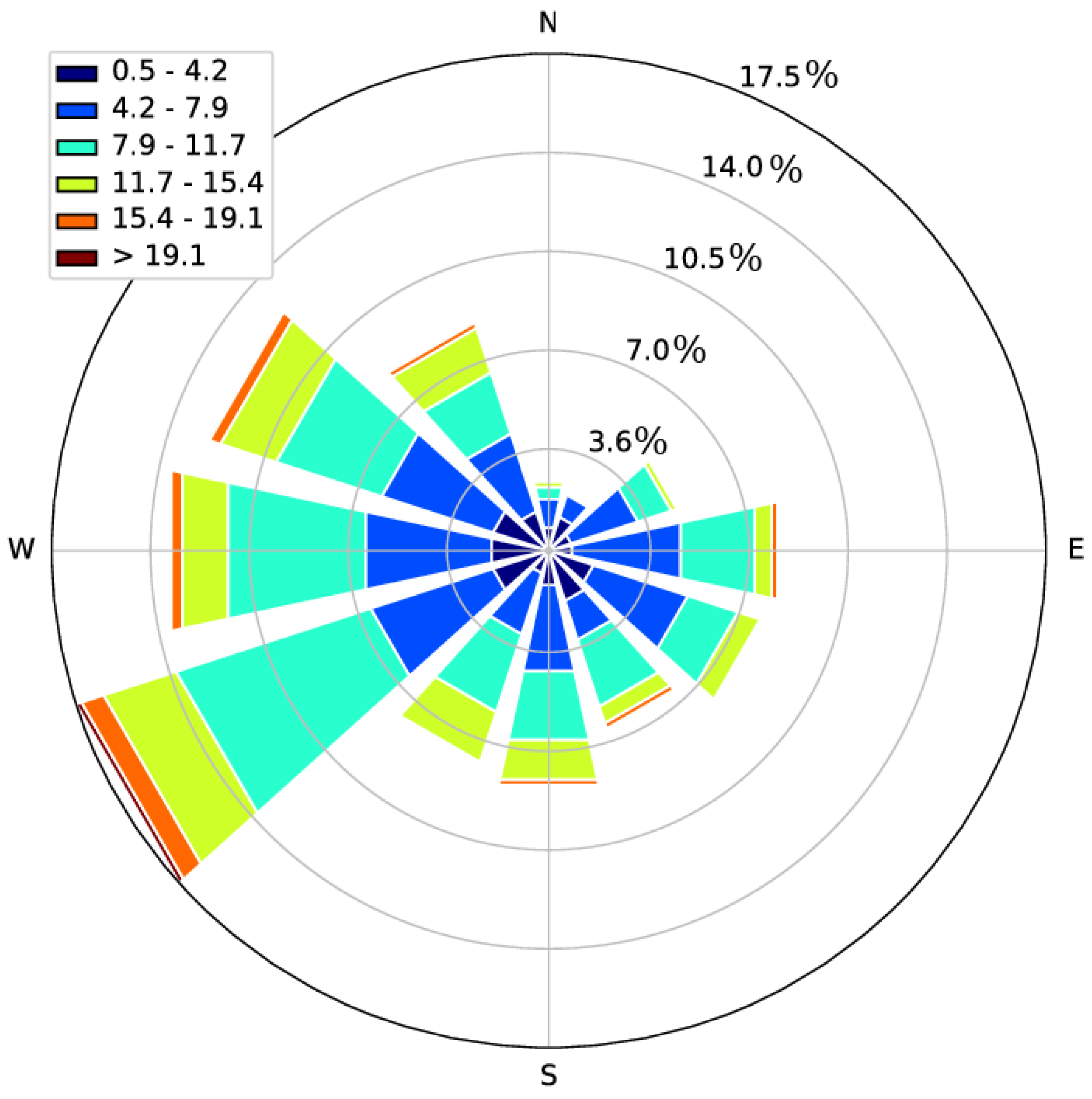
Figure 4 shows the distribution of wind directions for the period 2017–2020 at the location of the cluster N-4 for wind speed at 10 m height from DWD. The wind rose indicates a clear predominance of west/southwestly wind directions [51,52,53]. Previous studies showed a correlation between atmospheric stability and wind direction in the North Sea [10,51]. Based on FINO1 data [48], Emeis et al. [51] found that stable atmospheres are coupled with Southwest wind directions. Warmer air originating from land in southwesterly direction is advected eastward over the colder sea inducing stable stratification over the North Sea.
A clear seasonal variability is observed for the air-sea temperature difference and thus the thermal stability (Figure 5a–h). A climatology of the SST from DWD over the period 2017–2020 shows that the coolest temperature occurs during winter time in December–January–February (DJF) (see Figure 5a). The temperatures at the eastern and southern coast are cooler than the ones in the deeper sea because of the shallow depth near the shore. The same observation is made for the air temperature in winter (not shown), where the air is colder in general. Because of the shallow depth at the coast, the water cools faster there than in the deeper sea. This leads to weaker thermal stratification of the boundary layer further offshore than closer to land (see Figure 5b). In spring, the air starts heating up and the sea surface also gets warmed (Figure 5c). The thermal stability increases over the entire sea (Figure 5d). Relatively small differences in the thermal stability between the shallow and deep areas can be seen. The air temperature reaches its maximum in summer June-July-August (JJA), with highest values in the coastal regions (Figure 5e). As the sea surface temperatures are also at their highest in this season near the coast, the thermal stability ultimately decreases (Figure 5f). Higher instability is found in the shallow areas than in the deeper water, because the smaller water volume heats up faster. The transition from summer to autumn is characterised by a decrease of the air temperature. The sea surface temperature also decreases because of the air-sea interaction (Figure 5g). However, due to the higher heat capacity of the water, the sea surface is still warmer than the air, which causes unstable stratification with higher value in the sea (Figure 5h).
In the following, we introduce two case studies of the coastal effects in Section 3.2 and Section 3.3 to give a first impression of wind speed gradients derived from the SAR data, before a respective statistical analysis is presented in the subsequent sections. The first case on 6 April 2018 demonstrates a shape of horizontal wind speed gradients that is mostly frequently observed, whereas the second case on 25 August 2019 refers to an unusual decrease in the wind speed.

3.2. Example of Horizontal Wind Speed Gradient on 6 April 2018

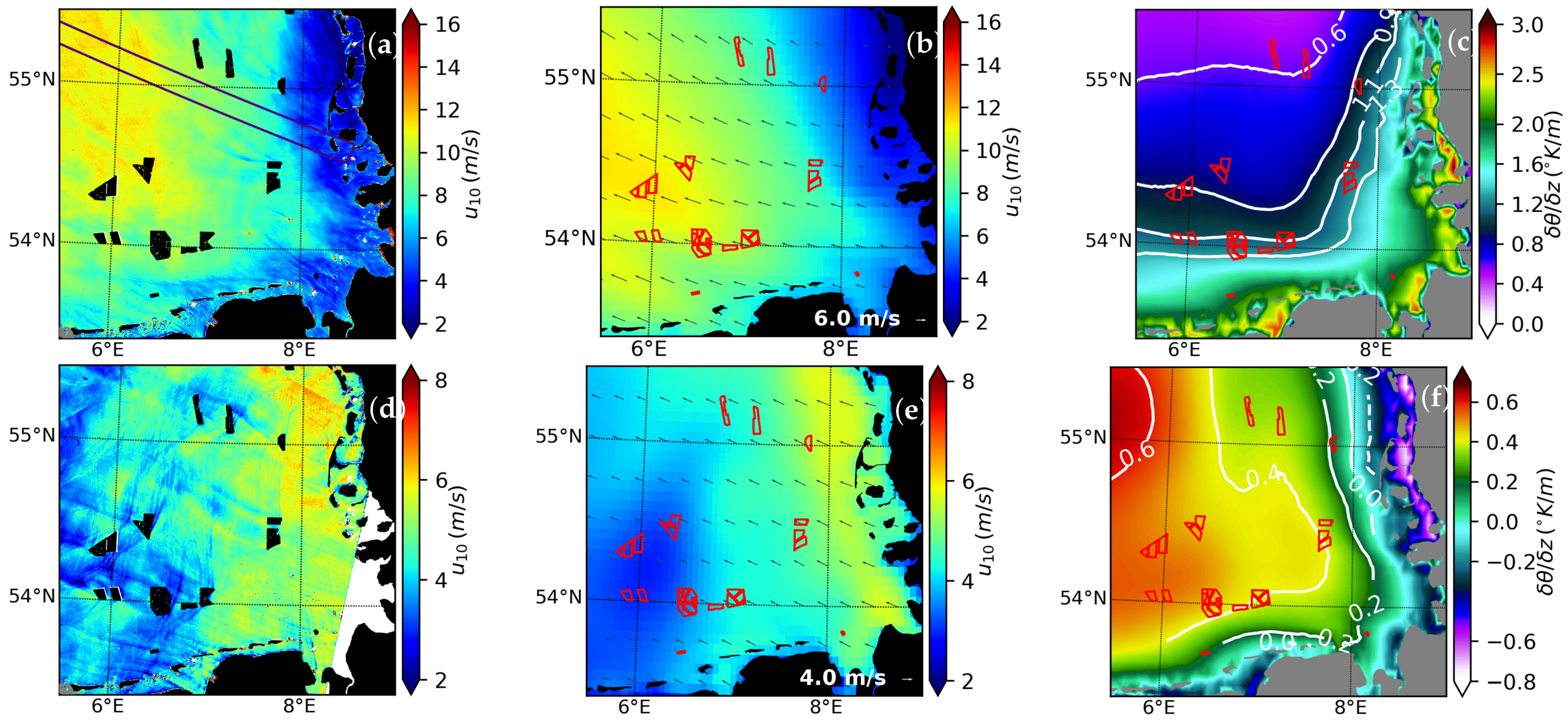
A typical example of increasing surface wind speeds with increasing distance from the shore is shown in Figure 6a,b. The 10 m SAR wind field displayed in Figure 6a was acquired on 6 April 2018 at 17:16UTC. The wind direction is from the east-south-east ( w d 109 ) as indicated by the DWD wind arrows in Figure 6b during the satellite overflight. The atmospheric condition is more stable (with higher thermal stability) as defined by Equation (21) (Figure 7c) closer to the coast than further offshore. Figure 7a shows the horizontal wind speed u 10 computed over the transect “Ref” (rectangle in Figure 6a). The wind speeds increase gradually with distance away from the coast. In addition, the respective water depths along the transect is shown in green with a separate vertical axis on the right. Similarly, in Figure 7b the thermal stability is superimposed as a green curve showing a decrease as u 10 increases away from the coast. It is clearly noticeable that following a more rapid wind increase in the initial part, the wind starts to adjust to an equilibrium after roughly 130 km distance offshore. The horizontal wind speed obtained with the empirical model given by Equation (10) (red dashed curve in Figure 7c,d) closely follows the observed SAR wind field. Based on the fitting procedure the parameters u l a n d and u o f f s h o r e are estimated as 3.8 m/s and 11.7 m/s, respectively. This yields a maximal absolute increase of 7.8 m/s. This is in good agreement with the horizontal evolution of the parameter δ u 10 in Figure 7c, which also shows a wind speed increase exceeding 7 m/s. The adjustment distance x 95 % is estimated as 166 km and is indicated by a yellow dashed line in Figure 7c. The estimation of the maximum of R u 10 shows more than 180% wind speed growth. The modelled wind speed increase δ u f and normalised wind increase R f using Equation (14), 15 (red dashed curves in Figure 7c,d), respectively, show good agreement with the observed quantities δ u 10 and R u 10 as well. R u 10 was estimated from Equation (17) with N p = 1 .
The increase of the horizontal wind speed is also confirmed by DWD (Figure 6b and blue curves in Figure 7a–d). However, although the wind near the coast is higher for DWD, the magnitude of the increase is far weaker (∼4.8 m/s and ∼120%) than for SAR. One explanation of this difference could be the coarser resolution of DWD. Therefore, in the following the statistical analysis are solely based on the high resolution SAR winds.

3.3. Example of Horizontal Wind Speed Gradient on 25 August 2019

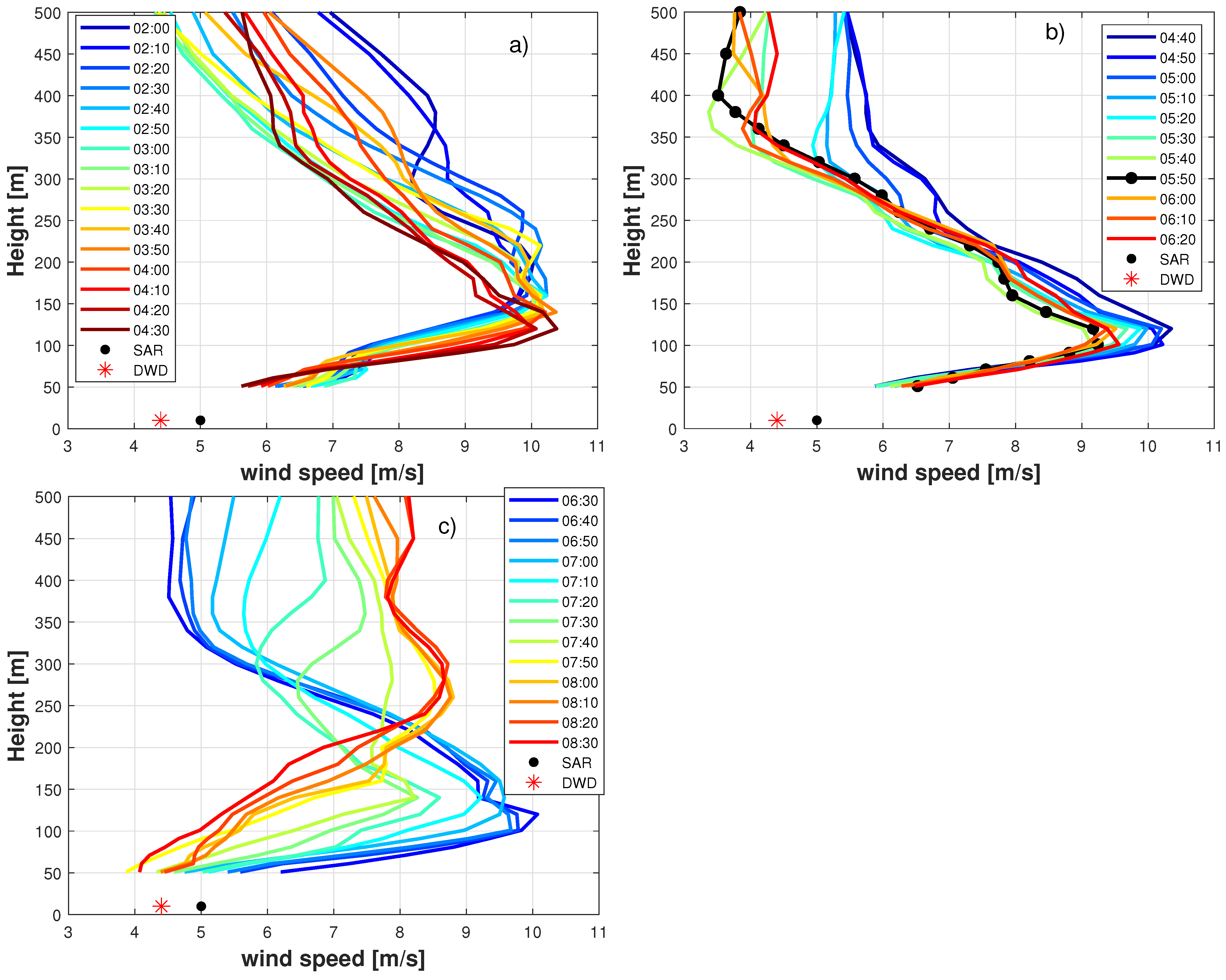
Unlike the previous case on 6 April 2018, this case illustrated in Figure 6d,e shows an unexpected behaviour for the horizontal wind speed. On 25 August 2019 at 05:48UTC, the observed 10 m SAR wind field (Figure 6d) indicates higher amplitudes near the land rather than far offshore, even though the wind direction comes from the land (wind arrows in Figure 6e). In other words, the wind speed decreases with distance away from the coast. The wind speed amplitude at the coast is about 6 m/s and drops below 4 m/s beyond 100 km offshore. The decrease of the horizontal wind speed observed in SAR is confirmed by the 10 m wind speed from DWD data (Figure 6e), which does not include any wind-farm parametrizations to take into account wakes generated behind the offshore wind farms. One has to mention that the analysis of the synoptic conditions reveals no precipitation and frontal structures that could potentially explain this unusual wind speed gradient. Higher values of stable stratification are found in the west, where the wind speed is also low (Figure 6f). The highest stability values are also found in this area of low wind speed. To understand the behaviour of the wind on 25 August 2019, we take a look at the vertical wind speed profiles measured by a wind LIDAR located at Norderney (Section 2.5.1, and Figure 1). The wind speed from SAR and DWD at Norderney is 5 m/s and 4.4 m/s, respectively, which is close to the lowest level’s LIDAR measurement. For further analysis, temporal evolution of the LIDAR wind profiles are also investigated. Figure 8a–c show the wind speed evolution (10 min time-step) for a period before, during and after the SAR overflight on 25 August 2019. Prior to the morning transition, a low-level jet (LLJ) with an average jet core height of about 200 m above ground is observed (Figure 8a), decreasing to 120 m around SAR acquisition time (Figure 8b). The jet is spread over a wider altitude band after 6:30UTC and finally starts to disappear around 8:00UTC (Figure 8c). This phenomenon is found to have a high frequency of occurrence between evening and morning at these latitudes [54].

3.4. Statistical Analysis: Horizontal Wind Speed Gradients

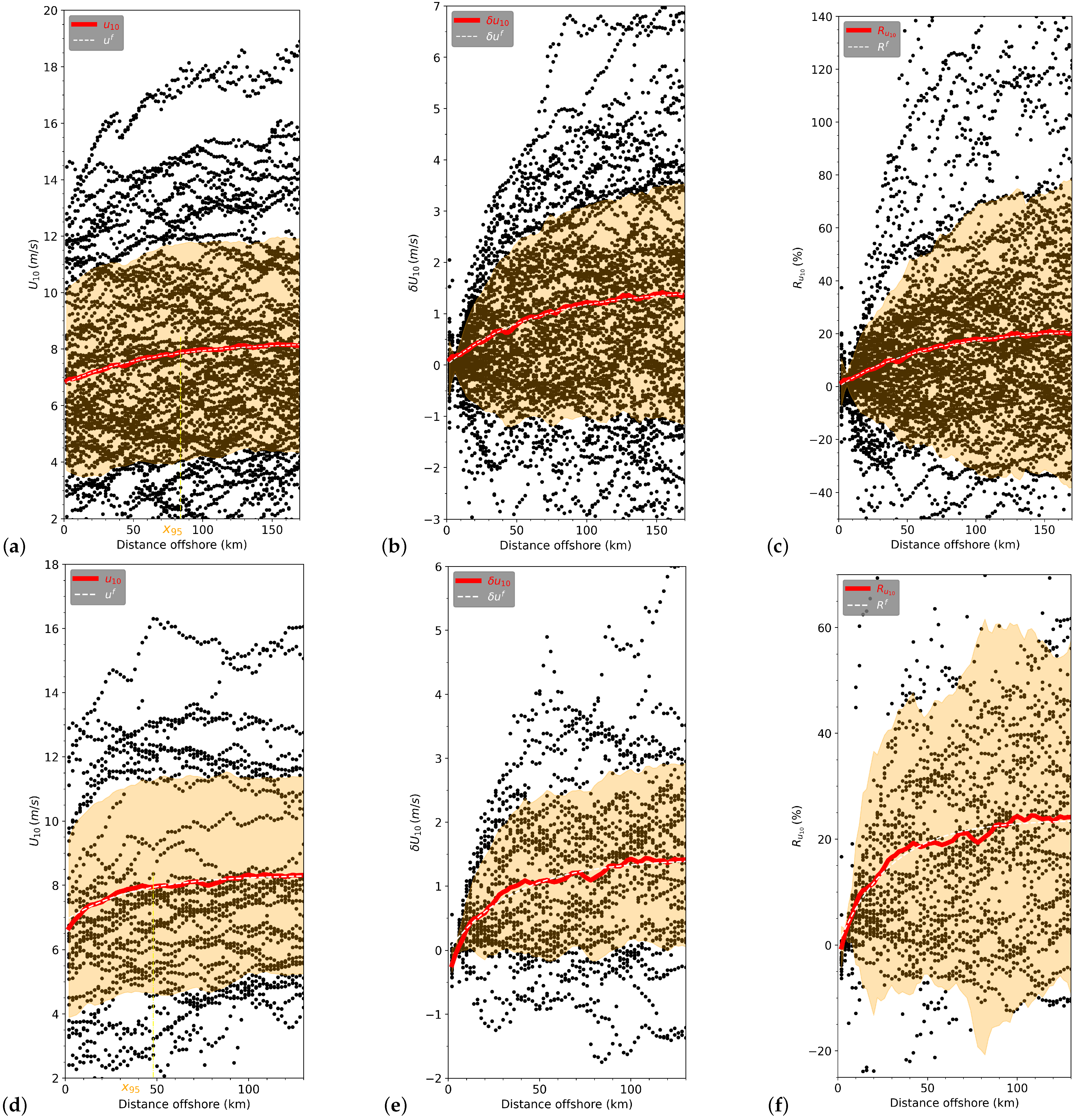
As mentioned in Section 2.1 and Section 2.3, SAR derived 10 m wind speeds over a period of four years are investigated. In the same way as in Section 3.2, the horizontal wind speed gradients are estimated considering the transect boxes set up in Section 2.3 for offshore wind directions. With respect to easterly winds with wind directions between 60 and 120 , 70 profiles are found for the entire four-year period (Table 1). A plot of all the wind speed transects of u 10 for easterly winds is displayed in Figure 9a–c. The u 10 curves show a general trend of the wind field from the coast to offshore. The mean wind speed gradient (red curve in Figure 9a) exhibits an overall progressive intensification of the wind speed with distance from the shore. On average, the wind speed increase is higher than 1 m/s in terms of absolute values (red curve, Figure 9b) and the relative normalised increase is about 20% (red curve, Figure 9c) beyond roughly 80 km offshore. The empirical model (yellow dotted line) indicates increases of the parameters Δ u , R m a x f , x 95 % of about 1.5 m/s, 22% and 84 km, respectively.
Similarly to the eastern wind speed gradients, southerly offshore winds are also analysed (Figure 9d–f). In this case the average wind transects of u 10 (red curve in Figure 9d) is also characterised by a rapid increase of the wind speed close to land. The wind speed increase δ u 10 exceeds 1.3 m/s beyond ∼50 km offshore (Figure 9e). Consistently, the empirical model indicates values for Δ u 10 and x 95 % of about 1.4 m/s and 38 km, respectively. The average relative increase R u 10 (red curve, Figure 9f) displays an overall growth above 18%, which is consistent with the estimate R m a x f of 20%.

3.5. Classification of Shape of Wind Speed Gradients

The detailed analysis of the horizontal wind speed gradients for easterly wind directions suggests that they can be classified into three main categories:
  • The horizontal wind speed transects of u 10 that increase with distance to the land (Figure 10a). They are hereafter referred to as “INCS”.
  • From the coast to offshore, the horizontal wind speed transects of u 10 that show a wind speed decrease with growing distance to land (Figure 10b). In the following these cases will be called “DECS”.
  • Some horizontal wind speed transects of u 10 display a delay in the wind speed increase, which begins further offshore (Figure 10c). These types are hereafter referred to as “LINCS” (Late INCreasing Samples).
There remains only a very small percentage of the samples (∼3%), that do not exhibit any clear trend and are thereby not classified according to the three categories defined above. As expected, the class “INCS” represents the highest percentage of the cases with about ∼60%. The “DECS” and “LINCS” classes represent, respectively, about 21% and 15% of the total samples (Table 2). This distribution is confirmed by the superimposed error bars for the three categories (gray vertical segments in Figure 10), which refer to the standard deviation of the estimator for the mean. The error bars are computed by dividing the sample standard deviation by the square root of the sample size. They indicate the interval of confidence, which is at the lowest amplitude for the “INCS” samples, but becomes increasingly larger moving from “DECS” to “LINCS”. The error bars around the mean wind speed gradients are bigger for southerly than for the easterly cases, because the uncertainty of the mean estimator grows due to smaller sample size.
The average of u 10 for the class “INCS” with easterly and southerly wind directions (Figure 10a,d and Figure 11a) shows an increase above 2.5 m/s and 1 m/s, respectively. By fitting of the empirical model the increase Δ u of 2.9 m/s (2.3 m/s) and an adjustment distance x 95 % of 90 km (38 km) for easterly (southerly) winds are found (Figure 11b,c). This indicates that the adjustment towards the equilibrium occurs over a shorter distance for southerly than easterly wind directions. Although the wind speeds far offshore are about the same magnitude (Figure 10a,d and Figure 11a), the relative increase (Figure 11b) is also lower for easterly than southerly winds as the wind speed close to land is slightly higher along the east coast of the German Bight. The normalised relative increase (Figure 11c) for easterly and southerly winds exceeds, respectively, 40% and 30% far offshore. The parameters Δ u and x 95 % for “INCS” cases are higher than the respective values estimated for the overall data set (Section 3.4). Interestingly, wind speed transects of u 10 for the class “INCS” seem to be associated with strong instability of the boundary layer (Figure 10a,d). For the class “DECS”, the wind speed transects of u 10 show an absolute decrease of about 2 m/s and 1 m/s for easterly and southerly winds, respectively, (Figure 10b,e). For both wind directions, the mean of u 10 for the class “LINCS” shown in Figure 10c,f seems to behave like the “DECS” mean in the first 40 km after which the wind speed starts increasing. The average magnitude of increase is about 2 m/s over 150 km offshore. Compared to “INCS”, the thermal gap is reduced between the air temperature and the SST, which ultimately lowers the instability of the boundary layer for the classes “DECS” and “LINCS”. The detailed inspection of the horizontal wind speed gradients for “LINCS” cases indicates that these are mostly satellite measurements taken in the morning (around 5UTC).
In the following, the rest of the analysis is mainly based on “INCS” cases since they are the most expected and frequent situations.

3.6. Distribution of the Parameters x 95 % , R m a x f , u l a n d and u o f f s h o r e , and Atmospheric Stability Dependence

The parameters x 95 % , R m a x f , Δ u , u l a n d , and u o f f s h o r e are estimated from SAR derived u 10 ( x ) transects with the empirical model Equation (10) to get an impression about their statistical distribution. The computation of these parameters are performed on the samples from the class “INCS” from combined easterly and southerly wind directions. Figure 12 shows respective histograms and scatter plots of these parameters. The histogram of the adjustment distance x 95 % in Figure 12a indicates that in most of the cases the adjustment distance is below 100 km, but still distances of 200 km and above can occur. As can be seen in Figure 12b, the wind speed increase Δ u grows with the adjustment distance x 95 % . The average Δ u and x 95 % of about 2.6 m/s and ∼67 km are, respectively, estimated. The distribution in Figure 12b–f also illustrates the stability dependence of the parameters x 95 % , u l a n d , u o f f s h o r e , Δ u and R m a x f (Equation (16)). Overall, the blue and red dots refer to the parameters derived from u 10 associated with unstable and stable thermal stratification, respectively. Figure 12c shows that the wind speed increase grows with the equilibrium wind speed offshore. According to the theoretical model Taylor [9] one would in fact expect a linear relationship, but as already explained in Section 2.2, this model is based on a number of simplifying assumptions. The growth of the wind speed increase with the wind speed offshore is seemingly higher for unstable than stable stratification.
The behaviour of the parameter R m a x f as a function of x 95 , u o f f s h o r e and u l a n d is illustrated in Figure 12d–f. For better visualisation the scale for R m a x f is not continuous, but is split into two parts separated by the hatched area. The parameter R m a x f noticeably grows with increasing adjustment distance and drops for higher values of u l a n d or u o f f s h o r e . It is interesting once again to remember that according to the theoretical model in Section 2.2 the normalised wind increase R m a x f should stay constant with regard to changes of either u l a n d or u o f f s h o r e , if a constant surface roughness ratio is assumed. Figure 12f indicates that the stable cases are usually linked to lower land wind speeds and that higher normalised increases can be observed in these conditions. Figure 12d–f also show that the longest adjustment distances are found for stable conditions. As explained before, this is to be expected, because unstable conditions accelerate the adjustment process. In the following we have a closer look at the stability dependence of the horizontal wind speed gradients.

3.7. Influence of the Atmospheric Stability on Wind Speed Gradients

An investigation of potential impacts of the thermal stability over the sea on the wind speed gradients is performed. The wind speed u 10 associated with thermally stable conditions are separated from the ones related to unstable stratification. This procedure is carried out for the dominating class “INCS” with a focus on the transects “Ref” (“Undisturbed” winds) and “N4”.

3.7.1. “Undisturbed” Horizontal Wind Speed Gradients

Figure 13a,d refer to the thermally stable (solid red line) and unstable (solid black line) samples for the “Ref” transect for easterly and southerly winds. Similarly to the structure of the horizontal wind speed gradients in Figure 10a, stable (“STA”) and unstable (“UNS”) cases display a strong initial speed up with growing distance from land until an equilibrium is reached. The mean wind speeds are in fact significantly lower for the stable cases for both wind directions. This observation was already made earlier in Figure 12c,e,f, which showed that most of the distribution of the estimated parameters u l a n d and u o f f s h o r e associated with unstable conditions (colored blue dots) had higher magnitude. The green curves refer to thermal stability and indicate a difference between stable and unstable cases of roughly 2.5 K/m and 1.5 K/m, respectively, for easterly and southerly winds.
The curves of R u 10 displayed in Figure 13b,d show higher normalised increases by approximately a factor of two for the stable cases for easterly winds, whereas a factor of about 1.5 is found for southerly winds. For both wind directions, the “UNS” cases intensify rapidly from the coast, but stabilised wind conditions appear to be achieved over a shorter distance for southerly winds. Likely, the “STA” increases over an extended distance to adjust to steady wind conditions. The distance over which the wind keeps increasing is beyond ∼90 km (40 km) and ∼120 km (60 km), respectively, for “UNS” and “STA” from easterly (southerly) winds. The computed adjustment distances x 95 % considering easterly winds are of about 72 km and 115 km for unstable and stable thermal stratification, respectively. However, the estimated adjustment distance x 95 % from southerly winds is about 30 km and 50 km for “UNS” and “STA”, respectively. Intuitively, this observation makes sense since higher turbulence can be expected to accelerate the adjustment processes in the boundary layer. Obviously, the adjustment distances from southerly winds are still relatively small in comparison to the values found for easterly winds. Although the wind speed increase from southerly winds seems relatively similar (not shown), the normalised wind speed increase R u 10 (Figure 13d) appears to be higher for “STA” than for “UNS”. The estimated parameters are summarised in Table 3.
It is interesting to note that the normalised wind speeds for unstable conditions are quite similar for easterly and southerly winds with maximum values of about 30%. These are also the conditions with significantly higher wind speeds. The major difference is found for the stable cases with maximum values of about 80% and 40%, respectively. One can also see that the stability of the stable cases is in fact slightly higher for the easterly wind directions. The wind speeds near the land in stable conditions are about 40% lower for easterly winds and the sea surface roughness, therefore smaller in the initial phase of sea-state development. Furthermore, the drag coefficient relating wind speed at 10 m height to friction velocity decreases with stability [55]. The fact that the drag coefficient is lower for stable conditions also indicates that the observed larger increase for easterly winds in neutral conditions is not an artefact of the SAR wind measurements, because one would expect a bias towards lower wind speeds in those conditions [56].

3.7.2. Interaction of Coastal Wind Speed Gradients with OWF Wakes

The OWF wakes are characterised by a deceleration of wind speed downwind from the wind farms. The length of the wakes depends on stability, where thermally stable boundary layers are favorable for longer wakes, while unstable stratification tends to diffuse wakes relatively quickly due to higher vertical momentum fluxes [16,17,38,50,53]. In the following we will have a closer look at the interaction of coastal effects with atmospheric wakes generated by the cluster N-4.
Figure 14a,b show the horizontal wind speed gradients for the class “INCS” that are associated with the thermally unstable stratification for the transects “Ref” and “N4” from easterly (a) and southerly (b) winds. The associated stability transects are superimposed as green curves with separate vertical axis on the right. The SAR measurements within the OWFs are contaminated by the strong radar reflection from wind turbines and are therefore not used for wind speed estimation. For both wind directions, as expected, the “Ref” cases presents continuous curves, with a rapid increase in the first 50 km followed by a nearly steady state. It is obvious that for easterly wind directions the cluster N-4 is located in an area with significant lateral wind speed gradients associated with coastal effects. For southerly wind directions the spatial variability of the background wind field within cluster N-4 is smaller because the upstream distance to the coast is longer and wind speeds are closer to equilibrium. Before impinging the cluster N-4, the “Ref” and “N4” relatively display comparable horizontal wind speed gradients. The main differences arise downstream of the wind farm with roughly 5% smaller wind speeds in the transect passing through the OWF. In easterly winds the wind speed downstream of the OWF is actually higher than upstream. This means that the impact of the wakes on the wind is more than compensated by the coastal effect. However, a slight negative slope or gap between the upstream and downstream wind amplitude that depicts wind deficit can be seen in the first 15 km after crossing the cluster N-4 for the southerly wind. This indicates wake impacts are still present in the downstream wind field. Overall, the horizontal wind speed gradients for “N4” show an increasingly weak slope downstream the wind farm in comparison to the “Ref” cases. The normalised wind speed increase (not shown) is lower for “N4” than for “Ref” for both wind directions.
In Figure 14c,d, u 10 for the class “INCS” related to stable stratification are considered. Upstream the wind farm, the wind speed amplitude from “Ref” is lower than “N4” for easterly winds (Figure 14c), while the wind field from “Ref” and “N4” are quite similar for southerly winds (Figure 14d). Overall, for easterly and southerly winds, the curves of u 10 from “N4” display a significant drop in wind amplitude immediately downstream the cluster N-4, which extends at least over 20–30 km. This wind speed decrease reflects the wake effects that have superimposed the background air flow. As a consequence of the wake superposition that reduces upstream wind speed, the horizontal wind speed gradient downstream has a stronger slope in the first 30 km than the reference horizontal wind speed gradient. This increases the horizontal wind speed gradient and therefore the adjustment distance towards the equilibrium. The wakes indeed subdivide the horizontal wind speed transect of u 10 into two horizontal wind speed gradients. The first horizontal wind speed gradient is the upstream wind starting from the shore to the cluster N-4 and is a result of the step in the surface roughness between the coast and the sea. The second horizontal wind speed gradient downstream the cluster N-4, starting from the highest reduced wind speed increases gradually towards a certain “normal” conditions, where the wake effects are attenuated. In this sense, the wind farms can also be considered as a surface rougher than the sea.
Obviously, the locations of the cluster N-4 on the curve of u 10 derived from easterly and southerly winds (Figure 14) are quite different. The cluster N-4 is about 35–50 km and 65 km far offshore with respect to eastern and southern coasts, respectively. The cluster N-4 is located where the wind speed is more or less stabilised for southerly wind direction. However, this is the opposite for easterly wind direction. Hence, this cluster undergoes stronger horizontal wind speed variations in easterly than southerly wind directions. This could lead to weaker (or no impact) on the power production for southerly than easterly winds.

4. Discussion

The investigation of the evolution of the horizontal wind field indicates that the wind intensifies gradually with growing distance away from the coast. Considering transects (Figure 2b) around the cluster N-4 the difference between horizontal winds offshore and the ones near the land is significant. The evolution of the horizontal wind fields can be defined as a two-phase process: The first phase concerns the rapid intensification of the wind speed and the second phase refers to the adaptation of wind to a relatively stable state far away from the coast. These observations are consistent with previous studies [57,58,59].
An average wind speed increase Δ u of about 1.5 m/s and 1.3 m/s for all classes combined for easterly and southerly winds is, respectively, found. The scaling of the wind speed increase with respect to u l a n d yields a mean normalised wind speed increase of more than 18% for both wind directions. The parameter u l a n d is estimated through the fitting of an empirical model, which is more stable than a direct use of satellite signals close to land. The detailed analysis of the structure of horizontal wind speed gradients for easterly and southerly winds reveals different behaviours of the wind field, which are classified into three categories: The class “INCS” predominantly represents about 60% while the class “DECS” and “LINCS” constitute about, respectively, 20% and 15% of all cases. The “INCS” cases represent what should be expected when the wind blows over a discontinuity in the surface roughness [8,60]. They obviously follow the two-phase process. Higher values for Δ u of about 2.9 m/s and 2.3 m/s are consistently estimated by the empirical model for, respectively, easterly and southerly winds. The adjustment distance x 95 % is evaluated to 91 km and 38 km for, respectively, easterly and southerly winds. Overall, a maximum of R u 10 of about 46% is found for easterly winds and of about 32% for southerly winds. Hence, R u 10 for southerly winds is two thirds lower than that for easterly winds, although the wind rose and the average wind field indicate that the magnitude of the wind fields for both wind directions are quite comparable and small. In addition, southerly winds appear to increase rapidly and adjust to a stable state over shorter distance in comparison to easterly winds. There is a possible reason for these differences of the adjustment distance between the easterly and southerly cases. One hypothesis is that this has to do with differences in the overall structure of the eastern and southern coastline in the German Bight. The bathymetry shows that the eastern coastline has a more fuzzy geometric structure with the North Frisian islands spread over a wider range of distances from the mainland compared to the East Frisian islands. This could explain why the boundary layer transition process appears to be smoother for easterly winds. Another possible explanation is related to differences in the stability for easterly and southerly winds. It became apparent in Figure 14 that stable situations have a higher stability for easterly than for southerly directions and unstable situations have a higher instability for easterly than for southerly directions. This is to some extend consistent with the stability roses shown in Platis et al. [61], although there is a strong stability increase in the south-west directional sector, that is partly included in the angular range used for our analysis of southerly wind directions.
The empirical model introduced in this study depicts quite well the horizontal wind speed gradient for both considered wind directions. It demonstrates that the horizontal wind speed gradients can be described by an exponential function. The statistical analysis of different variables simulated by the model with respect to the SAR data show that the majority of computed adjustment distances x 95 % are below 100 km. The wind speed over land u l a n d and offshore u o f f s h o r e associated with thermally stable stratification are related to lower wind speed amplitudes. Higher values of R m a x f appear to be associated with higher x 95 % , but are correlated with lower u l a n d and u o f f s h o r e . However, the relationship between R m a x f and the wind speeds is in contradiction with the theoretical model presented in Section 2.2. The fact that higher values of R m a x f are observed for lower wind speeds could be an indication that the missing sea-state dependence of the ocean surface roughness is a relevant deficit of the model. Overall, higher values of the normalised wind speed increase are also found in stable conditions.
The atmospheric stability has been proven to influence the structure of the horizontal wind speed gradients. Regardless of stability impacts, the horizontal winds commonly follow the usual two-phase process regarding the evolution of the wind field. The first phase originates in response to the wind crossing a step of two different surface roughnesses and characterised by an increase of wind speed [8,9,60]. The second phase is then determined by the stratification of the IBL above the sea. The adjustment distance x 95 % of about 75 km and 30 km for, respectively, easterly and southerly winds are estimated for the horizontal wind speed gradients associated with unstable conditions. For thermally stable stratification the adjustment distance x 95 % of about 115 km (50 km) for easterly (southerly) winds are found. Indeed, the adjustment distance is rather shorter in thermally unstable than stable conditions. This result is consistent with previous studies [7,19,62]. In unstable stratifications, the short distance is explained by the fact that strong mixing and turbulence force the winds to quickly adjust to an equilibrium and stable state. On the contrary, the induced strong wind shear in the stable stratification slows wind mixing and consequently extends the adjustment distance towards an equilibrium state. The parameter R u 10 is higher in general for stable than unstable conditions for both wind directions, but the average thermal stability is relatively lower for southerly winds. This is quite counter-intuitive, because one would expect smaller relative increases for higher stability as the airflow is more decoupled from surface roughness changes in this case. This could be another hint that nonlinear sea surface roughness effects related to sea-state development may be a factor to be considered in more details. In stable conditions and near the coast the wind speed appear to be lower for easterly winds than southerly ones. This difference indicates that the evolution of the boundary layer may be significantly different for easterly and southerly wind directions in stable conditions and this should be investigated in more details in future studies using additional information on vertical profiles.
The thermal stability varies with different seasons. Strong stability occurs in spring, while strong instability are found in autumn [10,13,51,63]. As the adjustment distance is affected by the atmospheric stability, it is also impacted by the seasonal variability of the atmospheric stratification. For instance, in early winter or autumn with unstable thermal stratification, the adjustment to equilibrium is accelerated. This leads to shorter adjustment distances in autumn than in spring, where stable conditions are expected.
Horizontal wind speed gradients are obviously influenced by wakes generated behind the wind farm. The impact of the wakes are detectable in the first 20–30 km right behind the cluster N-4, characterised by a lower wind amplitude in comparison to the incoming wind speed upstream the wind farm. As expected, the wind speed gradients are weakly impacted by wakes during unstable stratification, since wakes are short or recovered in these conditions because of the turbulence and mixing [13,17,53,64,65]. The horizontal wind speed gradient is therefore slightly reduced behind the cluster in unstable conditions for the two wind directions. In stable stratification, wakes strongly impact the horizontal wind speed gradient because these conditions are favorable for wakes. A strong wind deficit downstream the cluster N-4 changes the gradient of the horizontal wind speed. The resulting strong wind gradient affects the adjustment distance, which may become longer. The adjustment distance can also depend on the wake length and recovery. This need to be further investigated.
The coastal gradients are important for offshore wind energy [10]. The location of the wind farms regarding the horizontal wind speed transects of u 10 appears to be critical for the power production. The cluster N-4 is closer to the eastern than southern coast. The cluster N-4 is situated in-between the acceleration phase, where the wind speed is still at its lowest amplitude regarding easterly wind directions. This is the opposite for southerly winds, with the winds almost at the equilibrium level. This situation also applies to the cluster N-5, which is far from the southern coast. Consequently, the power production will be much more affected with easterly than southerly winds. However, this may not be the case for the cluster N-8 located far away from the eastern coast. In addition, the wind speed at the cluster N-8 has a higher wind amplitude than the one at the cluster N-4 and has almost recovered from the wake effects. Considering “INCS” measurements from both easterly and southerly winds, the average power-density ψ (Equation (19)) and the average normalised power density R ψ (Equation (20)) are computed. The power-density increase is estimated as about 0.3 kW/m2. As for the horizontal wind u 10 , the magnitude of R ψ is lower close to the shore, but increases moving with distance from the coast and levels off at 160%. The magnitude of R ψ represents more than twice the maximum of the R u 10 for horizontal wind gradients associated with stable conditions for easterly winds. It is also about four times as big as the respective normalised wind speed increase. These estimations refer obviously to the 10 m wind speeds provided by SAR, and are independent of any particular wind farm characteristics. These numbers show that coastal effects are significantly amplified if wind power is considered instead of wind speed. Further studies are required to translate these results to wind turbine hub heights.
The analysis of horizontal wind fields has also shown a significant number of cases with decreasing wind gradients (“DECS”). The wind at its highest amplitude at the coast, decreases gradually towards an equilibrium. Here, the first phase concerns the decrease, while the second phase refers to the adjustment towards an equilibrium state. The analysis of such cases reveals that “DECS” occur predominantly in stable conditions. The investigation of LIDAR profiles acquired over the same period suggests the occurrence of LLJs at low altitude at the coast in these situations. The higher wind speed amplitude near the coast could be explained by the presence of LLJs. Offshore winds are associated with the occurrence of an IBL due to the change in roughness. The IBL height grows with increasing distance from the coast until an equilibrium is reached. In the case of an LLJ the situation in the lower boundary layer is very much dominated by the high wind speeds within the jet. However, the relative warm water temperatures and the resulting instabilities lead to vertical diffusion of the jet with growing distance from the coast, i.e., higher near-surface wind speeds are predominantly found close to land where the LLJ originated. In stable stratification, the LLJs initially at the coast propagate gradually with distance away from the shore. While moving away from the coast, the LLJs are shifted to higher altitudes and leave lower wind speeds below. This results in decreasing wind speeds with growing distance from the coast.
The minority of cases represented by the profile class “LINCS” appears to be composed mostly of morning samples. These cases could be associated with a very stable nocturnal boundary over land, which is advected over the water in the morning. The high stability leads to a decoupling of the air from roughness changes of the surface, which could explain a delayed response of the boundary layer over the water.

5. Summary–Outlook

The study focused on the coastal effects in the German Bight, where numerous offshore wind farms are erected in the coastal zone. Statistical analysis of horizontal wind speed gradients with respect to winds blowing from the coast to the sea were performed. The study is solely based on the 10 m wind speed derived from SAR. Given the shape of the German Bight, predominant offshore winds are easterly, southerly and southwesterly winds. In order to enable the analysis of “undisturbed” wind speed gradients and its comparison with the potential influence of atmospheric wind farm wakes, the area around the wind farm cluster N-4 was chosen for the analysis. The focus of the study is on southerly and easterly winds, for which the wind direction is approximately perpendicular to the coastline. The investigations reveal that coastal effects are very pronounced in the German Bight. For both wind directions, and most of the cases (60%) a maximum relative and normalised wind speed increase about 2.6 m/s and 40% with growing distance from the coast is found. Also, large variations of the adjustment distance towards the equilibrium with maximum exceeding 170 km and an average of 67 km are showed. Overall, the horizontal wind speed gradients can be described by an exponential law. It was also shown that the wind speed increase in offshore direction is influenced by the thermal stability. The adjustment distance towards the equilibrium is longer for stable than for unstable stratification. The horizontal wind speed gradients are impacted by wakes, especially under stable stratification as these conditions are favorable for long wakes. Thus, strong gradient of horizontal wind downstream the cluster are found. Further investigations on the interaction between the wakes and the wind at the hub height and the internal boundary layer height are still needed. The location of the wind farm clusters with respect to the gradient of the wind speed can strongly affect the power production. Therefore, coastal effects need to be taken into account in the future planning of offshore wind farm installations. Differences between easterly and southerly wind directions with respect to the boundary layer adjustment length scale were discussed. It seems that the more rapid adjustment found for southerly wind directions is consistent with differences in the geometric shape of the coastline as well as with asymmetries of the boundary layer stability with respect to the wind direction. Further analysis is necessary to clarify the origin of this observation in more detail.
Unusual horizontal wind speed gradient cases, i.e., wind speed decreases with growing distance from the coast are found. These situations appear to happen predominantly in stable atmospheric stratification. In addition, the LIDAR measurements reveal that this behaviour could be associated with the occurrence of LLJs. The situations with negative wind speed gradient require further investigations concerning the different physical processes involved. In particular, the 3D dynamics of the boundary layer including vertical profiles of wind, temperature and humidity, as well as vertical fluxes of momentum and heat require more analyses. This study largely focuses on the analysis of horizontal wind fields at near surface levels. It has certainly limitations regarding insights into processes at higher altitudes and the structure of the internal boundary layer. The combination of SAR data with 3D model simulations (e.g., Weather Research and Forecasting (WRF)) or 3D reanalysis data (e.g., ERA5) could be an interesting approach to improve the process understanding in subsequent studies.
The coastal effects are of particular relevance for offshore wind energy, as the wind farms are mostly located in the complex transition area between the land and the ocean boundary layer. The optimal layout of a windfarm, e.g., the turbine spacing is a complicated problem even in a homogeneous boundary layer in equilibrium [66]. The optimization of wind farms in the land/sea transition zone is even more challenging and will certainly benefit from detailed information about the magnitude of the gradients and the associated length scales as given in this study. A practical approach is to use this information in engineering models used for layout optimization in industry, which do not take these effects into account sufficiently so far. A respective analysis will be the subject of future studies combining research and industry perspectives.

Author Contributions

B.D. and J.S.-S. conceptualized the study. B.D. was responsible for the methodology, presented analysis and writing. J.S.-S. and B.C. contributed to the analysis and writing. All authors have read and agreed to the published version of the manuscript.

Funding

The presented work was supported by the Federal Ministry for Economic Affairs and Energy (BMWi) in the framework of the project X-Wakes (grant number 03EE3008F).

Institutional Review Board Statement

Not applicable.

Informed Consent Statement

Not applicable.

Data Availability Statement

The Sentinel 1 data can be found at https://scihub.copernicus.eu/ (last access: 28 February 2022).

Acknowledgments

The X-Wakes project is funded by the German Federal Ministry of Economic Affairs and Energy (BMWi) under grant number 03EE3008F in the framework of the project X-Wakes. The authors thank the European Space Agency for making Sentinel-1 SAR data and the snap toolbox freely available. They would also like to thank the partners from the project X-Wakes for interesting and helpful discussions.

Conflicts of Interest

The authors declare that the research was conducted in the absence of any commercial or financial relationships that could be construed as a potential conflict of interest.

References

  1. Deutsche WindGuard GmbH. Status des Offshore—Windenergieausbaus Deutschland—Status 2020; Deutsche WindGuard GmbH: Varel, Germany, 2020. [Google Scholar]
  2. IEA. Offshore Wind Outlook; Technical Report; IEA: Paris, France, 2019. [Google Scholar]
  3. Lee, J.; Zhao, F. Global Wind Report 2021; Technical Report; Global Wind Energy Council (GWEC): Brussels, Belgium, 2021. [Google Scholar]
  4. Ramírez, L.; Fraile, D.; Brindley, G. Offshore Wind in EuropeKey Trends and Statistics 2019; Technical Report; WindEurope: Brussels, Belgium, 2020. [Google Scholar]
  5. Van Der Laan, M.; Pena, A.; Volker, P.; Hansen, K.S.; Sørensen, N.N.; Ott, S.; Hasager, C.B. Challenges in simulating coastal effects on an offshore wind farm. J. Phys. Conf. Ser. IOP Pub. 2017, 854, 012046. [Google Scholar] [CrossRef] [Green Version]
  6. Schulz-Stellenfleth, J.; Emeis, S.; Dörenkämper, M.; Bange, M.; Canadillas, B.; Neumann, T.; Schneemann, J.; Weber, I.; zum Berge, K.; Platis, A.; et al. Coastal impacts on offshore wind farms—A review focussing on the German Bight area. Meteorol. Z. 2022; accepted for Publication. [Google Scholar]
  7. Lange, B.; Larsen, S.; Højstrup, J.; Barthelmie, R. Importance of thermal effects and sea surface roughness for offshore wind resource assessment. J. Wind Eng. Ind. Aerodyn. 2004, 92, 959–988. [Google Scholar] [CrossRef] [Green Version]
  8. Taylor, P.A. A model of airflow above changes in surface heat flux, temperature and roughness for neutral and unstable conditions. Bound.-Layer Meteorol. 1970, 1, 18–39. [Google Scholar] [CrossRef]
  9. Taylor, P. On wind and shear stress profiles above a change in surface roughness. Q. J. R. Meteorol. Soc. 1969, 95, 77–91. [Google Scholar] [CrossRef]
  10. Dörenkämper, M.; Optis, M.; Monahan, A.; Steinfeld, G. On the Offshore Advection of Boundary-Layer Structures and the Influence on Offshore Wind Conditions. Bound.-Layer Meteorol. 2015, 155, 459–482. [Google Scholar] [CrossRef]
  11. Dörenkämper, M.; Witha, B.; Steinfeld, G.; Heinemann, D.; Kühn, M. The impact of stable atmospheric boundary layers on wind-turbine wakes within offshore wind farms. J. Wind Eng. Ind. Aerodyn. 2015, 144, 146–153. [Google Scholar] [CrossRef] [Green Version]
  12. Lehner, S.; Horstmann, J.; Koch, W.; Rosenthal, W. Mesoscale wind measurements using recalibrated ERS SAR images. J. Geophys. Res. Oceans 1998, 103, 7847–7856. [Google Scholar] [CrossRef]
  13. Djath, B.; Schulz-Stellenfleth, J. Wind speed deficits downstream offshore wind parks—A new automised estimation technique based on satellite synthetic aperture radar data. Meteorol. Z. 2019, 28, 499–515. [Google Scholar] [CrossRef]
  14. Ahsbahs, T.; Badger, M.; Volker, P.; Hansen, K.S.; Hasager, C.B. Applications of satellite winds for the offshore wind farm site Anholt. Wind Energy Sci. 2018, 3, 573–588. [Google Scholar] [CrossRef] [Green Version]
  15. Hasager, C.B.; Badger, M.; Peña, A.; Larsén, X.G.; Bingöl, F. SAR-based wind resource statistics in the Baltic Sea. Remote Sens. 2011, 3, 117–144. [Google Scholar] [CrossRef] [Green Version]
  16. Li, X.; Lehner, S. Observation of TerraSAR-X for studies on offshore wind turbine wake in near and far fields. IEEE J. Sel. Top. Appl. Earth Obs. Remote Sens. 2013, 6, 1757–1768. [Google Scholar] [CrossRef] [Green Version]
  17. Djath, B.; Schulz-Stellenfleth, J.; Canadillas, B. Impact of atmospheric stability on X-band and C-band Synthetic Aperture Radar imagery of offshore windpark wakes. J. Sustain. Renew. Energy 2018, 10, 043301. [Google Scholar] [CrossRef] [Green Version]
  18. Ahsbahs, T.; Maclaurin, G.; Draxl, C.; Jackson, C.R.; Monaldo, F.; Badger, M. US East Coast synthetic aperture radar wind atlas for offshore wind energy. Wind Energy Sci. 2020, 5, 1191–1210. [Google Scholar] [CrossRef]
  19. Barthelmie, R.; Badger, J.; Pryor, S.; Hasager, C.B.; Christiansen, M.B.; Jørgensen, B. Offshore coastal wind speed gradients: Issues for the design and development of large offshore windfarms. Wind Eng. 2007, 31, 369–382. [Google Scholar] [CrossRef]
  20. Becker, G.A.; Dick, S.; Dippner, J.W. Hydrography of the German Bight. Mar. Ecol. Progress Ser. 1992, 91, 9–18. [Google Scholar] [CrossRef]
  21. Schulz-Stellenfleth, J.; Stanev, E.V. Analysis of the upscaling problem—A case study for the barotropic dynamics in the North Sea and the German Bight. Ocean Model. 2016, 100, 109–124. [Google Scholar] [CrossRef]
  22. Torres, R.; Snoeij, P.; Geudtner, D.; Bibby, D.; Davidson, M.; Attema, E.; Potin, P.; Rommen, B.; Floury, N.; Brown, M.; et al. GMES Sentinel-1 mission. Remote Sens. Environ. 2012, 120, 9–24. [Google Scholar] [CrossRef]
  23. Peter, H.; Jaggi, A.; Fernández, J.; Escobar, D.; Ayuga, F.; Arnold, D.; Wermuth, M.; Hackel, S.; Otten, M.; Simons, W.; et al. Sentinel-1A—First precise orbit determination results. Adv. Space Res. 2017, 60, 879–892. [Google Scholar] [CrossRef]
  24. GEBCO Compilation Group. GEBCO 2020 Grid; GEBCO Compilation Group: Paris, France, 2020. [Google Scholar]
  25. Koch, W. Directional Analysis of SAR images aiming at wind direction. IEEE Trans. Geosci. Remote Sens. 2004, 42, 702–710. [Google Scholar] [CrossRef]
  26. Koch, W.; Feser, F. Relationship between SAR-Derived Wind Vectors and Wind at 10 m Height Represented by a Mesoscale Model. Mon. Weather Rev. 2006, 134, 1505–1517. [Google Scholar] [CrossRef] [Green Version]
  27. Chapron, B.; Fouhaily, T.; Kerbaol, V. Calibration and Validation of ERS Wave Mode Products. Document DRO/OS/95-02; Institut Français de Recherche pour l’Exploitation de la Mer: Brest, France, 1995. [Google Scholar]
  28. Kerbaol, V.; Chapron, B.; Vachon, P.W. Analysis of ERS-1/2 synthetic aperture radar wave mode imagettes. J. Geophys. Res. Oceans 1998, 103, 7833–7846. [Google Scholar] [CrossRef]
  29. Benassai, G.; Di Luccio, D.; Corcione, V.; Nunziata, F.; Migliaccio, M. Marine spatial planning using high-resolution synthetic aperture radar measurements. IEEE J. Ocean. Eng. 2018, 43, 586–594. [Google Scholar] [CrossRef]
  30. Zou, Q.; He, Y.; Perrie, W.; Vachon, P.W. Wind-vector estimation for RADARSAT-1 SAR images: Validation of wind-direction estimates based upon geometry diversity. IEEE Geosci. Remote Sens. Lett. 2007, 4, 176–180. [Google Scholar] [CrossRef]
  31. Portabella, M.; Stoffelen, A.; Johannessen, J.A. Toward an optimal inversion method for synthetic aperture radar wind retrieval. J. Geophys. Res. Oceans 2002, 107, 1–13. [Google Scholar] [CrossRef]
  32. Zuhlke, M.; Fomferra, N.; Brockmann, C.; Peters, M.; Veci, L.; Malik, J.; Regner, P. SNAP (Sentinel Application Platform) and the ESA Sentinel 3 Toolbox. In Proceedings of the Sentinel-3 for Science Workshop, Venice, Italy, 2–5 June 2015; Volume 734, p. 21. [Google Scholar]
  33. Verhoef, A.; Portabella, M.; Stoffelen, A.; Hersbach, H. CMOD5. n-the CMOD5 GMF for Neutral Winds; Technical Report SAF/OSI/CDOP/KNMI/TEC/TN/3, 165; KNMI: De Bilt, The Netherlands, 2008. [Google Scholar]
  34. Leelössy, Á.; Molnár, F.; Izsák, F.; Havasi, Á.; Lagzi, I.; Mészáros, R. Dispersion modeling of air pollutants in the atmosphere: A review. Open Geosci. 2014, 6, 257–278. [Google Scholar] [CrossRef]
  35. Rodrigo, J.S.; Cantero, E.; García, B.; Borbón, F.; Irigoyen, U.; Lozano, S.; Fernande, P.; Chávez, R. Atmospheric stability assessment for the characterization of offshore wind conditions. J. Phys. Conf. Ser. IOP Publ. 2015, 625, 012044. [Google Scholar] [CrossRef] [Green Version]
  36. Charnock, H. Wind stress on a water surface. Q. J. R. Meteorol. Soc. 1955, 81, 639–640. [Google Scholar] [CrossRef]
  37. Alpers, W.; Hennings, I. A theory of the imaging mechanism of underwater bottom topography. J. Geophys. Res. 1984, 89, 1029–10546. [Google Scholar]
  38. Christiansen, M.B.; Hasager, C.B. Using Airborne and Satellite SAR for Wake Mapping Offshore. Wind Energy 2006, 9, 437–455. [Google Scholar] [CrossRef]
  39. Sjöholm, M.; Wagner, R.; Lindelöw, P. Commercial lidar profilers for wind energy. A comparative guide. In Proceedings of the European Wind Energy Conference and Exhibition 2008, Brussels, Belgium, 31 March–3 April 2008; Volume 6. [Google Scholar]
  40. Courtney, M.; Wagner, R.; Lindelöw, P. Testing and comparison of LIDARs for profile and turbulence measurements in wind energy. IOP Conf. Ser. Earth Environ. Sci. 2008, 1, 012021. [Google Scholar] [CrossRef]
  41. Canadillas, B.; Westerhellweg, A.; Neumann, T. Testing the performance of a ground-based wind LiDAR system: One year intercomparison at the offshore platform FINO1. DEWI Mag. 2011, 38, 58–64. [Google Scholar]
  42. Goit, J.; Shimada, S.; Kogaki, T. Can LiDARs Replace Meteorological Masts in Wind Energy? Energies 2019, 12, 3680. [Google Scholar] [CrossRef] [Green Version]
  43. Rausch, T.; Schuchard, M.; Ca nadillas, B.; Lampert, A. One Year Measurements of Vertical Profiles of Wind Speed and Wind Direction from 40 to 500 m at Heligoland, German Bight, North Sea, Germany; Technische Universität Braunschweig, PANGAEA: Braunschweig, Germany, 2020. [Google Scholar] [CrossRef]
  44. Schulz-Stellenfleth, J.; Lampert, A.; Emeis, S.; Dörenkämper, M.; Bange, J.; Ca nadillas, B.; Neumann, T.; Schneemann, J.; Weber, I.; zum Berge, K.; et al. Coastal impacts on offshore wind farms. Meteorol. Z. (Contrib. Atmosph. Sci.), 2021; submitted. [Google Scholar]
  45. Wan, H.; Giorgetta, M.A.; Zängl, G.; Restelli, M.; Majewski, D.; Bonaventura, L.; Fröhlich, K.; Reinert, D.; Rípodas, P.; Kornblueh, L.; et al. The ICON-1.2 hydrostatic atmospheric dynamical core on triangular grids–Part 1: Formulation and performance of the baseline version. Geosci. Model Dev. 2013, 6, 735–763. [Google Scholar] [CrossRef] [Green Version]
  46. Zängl, G.; Reinert, D.; Rípodas, P.; Baldauf, M. The ICON (ICOsahedral Non-hydrostatic) modelling framework of DWD and MPI-M: Description of the non-hydrostatic dynamical core. Q. J. R. Meteorol. Soc. 2015, 141, 563–579. [Google Scholar] [CrossRef]
  47. Stark, J.D.; Donlon, C.J.; Martin, M.J.; McCulloch, M.E. OSTIA: An operational, high resolution, real time, global sea surface temperature analysis system. In Proceedings of the OCEANS 2007—Europe, Aberdeen, UK, 18–21 June 2007; pp. 1–4. [Google Scholar] [CrossRef]
  48. Fino123 Homepage. FINO—Forschungsplattformen in Nord- und Ostsee; Fino123: Kiel, Germany, 2021. [Google Scholar]
  49. Borsche, M.; Kaiser-Weiss, A.K.; Kaspar, F. Wind speed variability between 10 and 116 m height from the regional reanalysis COSMO-REA6 compared to wind mast measurements over Northern Germany and the Netherlands. Adv. Sci. Res. 2016, 13, 151–161. [Google Scholar] [CrossRef] [Green Version]
  50. Platis, A.; Bange, J.; Bärfuss, K.; Canadillas, B.; Hundhausen, M.; Djath, B.; Lampert, A.; Schulz-Stellenfleth, J.; Siedersleben, S.; Neumann, T.; et al. Long-range modifications of the wind field by offshore wind parks—Results of the project WIPAFF. Meteorol. Z. 2020, 29, 355–376. [Google Scholar] [CrossRef]
  51. Emeis, S.; Siedersleben, S.; Lampert, A.; Platis, A.; Bange, J.; Djath, B.; Schulz-Stellenfleth, J.; Neumann, T. Exploring the wakes of large offshore wind farms. J. Phys. Conf. Ser. IOP Pub. 2016, 753, 092014. [Google Scholar] [CrossRef] [Green Version]
  52. Platis, A.; Siedersleben, S.K.; Bange, J.; Lampert, A.; Bärfuss, K.; Hankers, R.; Cañadillas, B.; Foreman, R.; Schulz-Stellenfleth, J.; Djath, B.; et al. First in situ evidence of wakes in the far field behind offshore wind farms. Sci. Rep. 2018, 8, 2163. [Google Scholar] [CrossRef]
  53. Cañadillas, B.; Foreman, R.; Barth, V.; Siedersleben, S.; Lampert, A.; Platis, A.; Djath, B.; Schulz-Stellenfleth, J.; Bange, J.; Emeis, S.; et al. Offshore wind farm wake recovery: Airborne measurements and its representation in engineering models. Wind Energy 2020, 23, 1249–1265. [Google Scholar] [CrossRef]
  54. Wagner, D.; Steinfeld, G.; Witha, B.; Wurps, H.; Reuder, J. Low Level Jets over the Southern North Sea. Meteorol. Z. 2019, 28, 389–415. [Google Scholar] [CrossRef]
  55. Zou, Z.; Zhao, D.; Liu, B.; Zhang, J.A.; Huang, J. Observation-based parameterization of air-sea fluxes in terms of wind speed and atmospheric stability under low-to-moderate wind conditions. J. Geophys. Res. Oceans 2017, 122, 4123–4142. [Google Scholar] [CrossRef]
  56. Takeyama, Y.; Ohsawa, T.; Kozai, K.; Hasager, C.B.; Badger, M. Comparison of geophysical model functions for SAR wind speed retrieval in Japanese coastal waters. Remote Sens. 2013, 5, 1956–1973. [Google Scholar] [CrossRef] [Green Version]
  57. Mulhearn, P. On the formation of a stably stratified internal boundary-layer by advection of warm air over a cooler sea. Bound.-Layer Meteorol. 1981, 21, 247–254. [Google Scholar] [CrossRef]
  58. Garratt, J.; Ryan, B. The structure of the stably stratified internal boundary layer in offshore flow over the sea. Bound.-Layer Meteorol. 1989, 47, 17–40. [Google Scholar] [CrossRef]
  59. Barthelmie, R.; Palutikof, J. Coastal wind speed modelling for wind energy applications. J. Wind Eng. Ind. Aerodyn. 1996, 62, 213–236. [Google Scholar] [CrossRef]
  60. Garratt, J. The internal boundary layer—A review. Bound.-Layer Meteorol. 1990, 50, 171–203. [Google Scholar] [CrossRef]
  61. Platis, A.; Hundhausen, M.; Lampert, A.; Emeis, S.; Bange, J. The Role of Atmospheric Stability and Turbulence in Offshore Wind-Farm Wakes in the German Bight. Bound.-Layer Meteorol. 2021, 182, 441–469. [Google Scholar] [CrossRef]
  62. Pryor, S.; Barthelmie, R. Analysis of the effect of the coastal discontinuity on near-surface flow. Ann. Geophys. 1998, 16, 882–888. [Google Scholar] [CrossRef]
  63. Emeis, S. A simple analytical wind park model considering atmospheric stability. Wind Energy 2010, 13, 459–469. [Google Scholar] [CrossRef]
  64. Christiansen, M.B.; Hasager, C.B. Wake effects of large offshore wind farms identified from satellite SAR. Remote Sens. Environ. 2005, 98, 251–268. [Google Scholar] [CrossRef]
  65. Platis, A.; Hundhausen, M.; Siedersleben, S.; Lampert, A.; Bärfuss, K.; Schulz-Stellenfleth, J.; Djath, B.; Emeis, S.; Neumann, T.; Canadillas, B.; et al. Evaluation of a simple analytical model for offshore wind farm wake recovery by in-situ data and Forecasting simulations. Wind Energy 2020, 24, 212–228. [Google Scholar] [CrossRef]
  66. Meyers, J.; Meneveau, C. Optimal turbine spacing in fully developed wind farm boundary layers. Wind Energy 2012, 15, 305–317. [Google Scholar] [CrossRef] [Green Version]
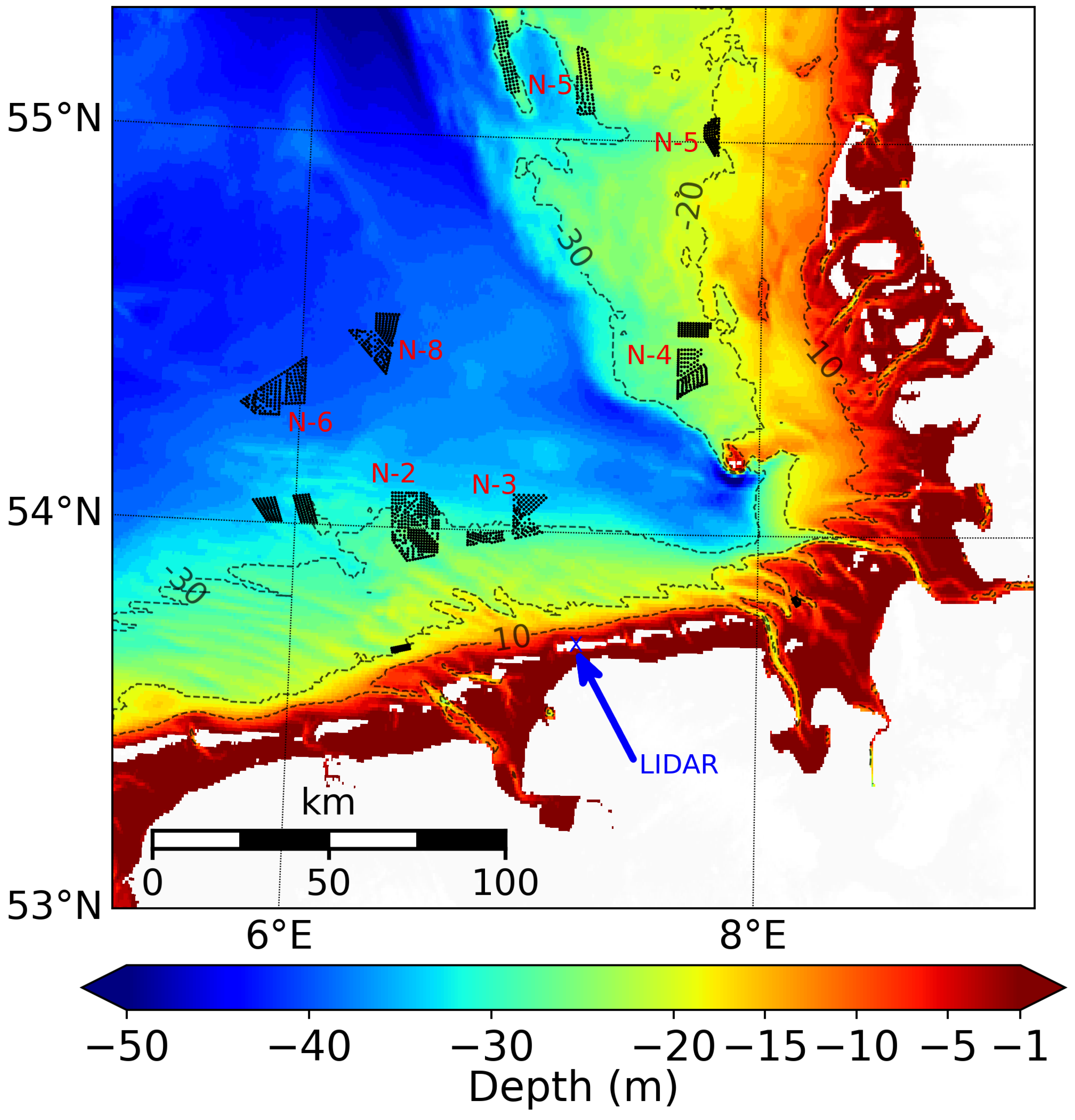
Figure 1. Water depths in the German Bight [24]. The black dots correspond to offshore wind turbines installed by June 2020. The blue arrow indicates the location of the LIDAR (see Section 2.5.1).
Remotesensing 14 01688 g001
Figure 2. Sentinel-1A/B coverage of the entire German Bight (a). Red swath corresponds to ascending orbits (acquired around 17:16UTC) and the blue frame refers to descending orbits (acquired around 05:48UTC). (b) Map showing bathymetry contours with transects over which the wind speed gradients are estimated. The rectangular box in purple represents the transect “Ref” in an area without influence of atmospheric wakes, while the black box indicates the transect through the cluster N-4 (“N4”).
Remotesensing 14 01688 g002
Figure 3. (a) Profiles of normalised wind speeds with z l a n d / z s e a = 55 at different normalised downstream distances for neutral conditions. (b) Associated normalised stress profiles. (c) Downstream transects of normalised wind speeds at two normalised heights z/ z s e a = 10 5 (solid lines) and z/ z s e a = 10 6 (dashed lines). Colors refer to different stabilities of the boundary layer with neutral in green, stable in blue and unstable in red. (d) Sea surface roughness length as a function of 10 m wind speed for a fully developed sea state according to Charnock.
Remotesensing 14 01688 g003
Figure 4. Wind rose computed from DWD data for the wind speed at 10 m height around the cluster N-4 location.
Remotesensing 14 01688 g004
Figure 5. Mean SST and mean thermal stability for the seasons in (a,b) winter (DJF), (c,d) spring (MAM), (e,f) summer (JJA) and (g,h) autumn (SON) from DWD for the period 2017–2020. The black polygons represent the wind farm locations.
Remotesensing 14 01688 g005
Figure 6. (ac): 10 m wind speed from SAR on 6 April 2018 at 17:16UTC (a), DWD colocated 10 m wind (b), and thermal stability from DWD (b). (ce): 10 m wind speed on 25 August 2019 around 05:48UTC from SAR (d), colocated wind and thermal stability from DWD, respectively, in (e,f). The rectangular purple box represents the transect “Ref” in an area without any influence of atmospheric wakes. Red polygons indicate wind farm locations.
Remotesensing 14 01688 g006
Figure 7. (a,b): Corresponding horizontal wind speed gradient of 10 m wind speed from SAR (purple) and DWD (blue) with superimposed curves for bathymetry (green) (a) and for thermal stability (green) (b). The orange dashed line at x 95 marks the adjustment distance according to Equation (12). (c,d): Wind speed increase δ u 10 (c) and normalised wind speed increase R u 10 (d). The purple and blue curves, respectively, refer to SAR and DWD. The red curves in (ad) corresponds to the fitted model given by Equations (10), (14) and (15), respectively.
Remotesensing 14 01688 g007
Figure 8. (ac): Vertical profiles of wind speed from wind LIDAR on 25 August 2019 before the time (a), at the time (b) and after the time (c) of satellite measurement. Black dots and red star symbols represent, respectively, the wind speed from SAR and DWD at the location of the LIDAR.
Remotesensing 14 01688 g008
Figure 9. (ac) 10 m wind speed derived from Sentinel 1A/B (dots) for easterly winds for 2017–2020 along the transect “Ref” in Figure 2b (a). The corresponding parameters δ u 10 , R u 10 are displayed in (b,c), respectively. (df): The same as (ac) but for southerly winds for 2017–2020 along the transect “Ref” (d) and corresponding δ u 10 (e) and R u 10 (f). The red, yellow and white dashed curves represent, respectively, the mean value, the standard deviation and the empirical model fits (Equations (10), (14) and (15)).
Remotesensing 14 01688 g009
Figure 10. (ac): Mean wind speed gradients for classes “INCS” (a), “DECS” (b) and “LINCS” (c) for easterly winds. Air and sea surface temperatures from DWD are, respectively, shown as dashed and solid green lines. (df): The same as (ac), but for southerly winds. The blue and orange dashed lines in (a,b,d) refer to the fitted empirical model.
Remotesensing 14 01688 g010
Figure 11. (ac): Comparison of absolute wind speed (a), wind speed increase (b) and normalised wind speed increase (c) for easterly (red) and southerly (black) winds for “INCS” class. The blue and orange dashed lines in (b,c) refer to the fitted empirical model.
Remotesensing 14 01688 g011
Figure 12. Statistical distribution of estimated parameters x 95 % , Δ u , R m a x f , u l a n d , u o f f s h o r e with respect to thermal stratification from combined wind directions. Histogram of the adjustment distance x 95 % (a). Scatter plots of wind increase Δ u versus x 95 % (b) and versus u o f f s h o r e (c). Scatter plots of maximum normalised wind increase R m a x f versus x 95 % (d), versus u o f f s h o r e (e), and versus u l a n d (f). The hatched areas separate the top and low frames, which have different scaling in the vertical axis. Blue and red colors refer to unstable and stable cases, respectively.
Remotesensing 14 01688 g012
Figure 13. (a,b): Horizontal wind speed gradients (a) and normalised wind speeds (b) for stable (solid red) and unstable (solid black) cases from the “INCS” class for easterly winds. (c,d): The same as (a,b) for southerly wind directions. In (a,c) stable cases (red curves) refer to the scale of the right vertical axis (red) and unstable cases to the scale of left vertical axis (black). Green curves represent thermally stable (solid line) and unstable (dashed line) conditions and refer to the extra green scale on the right. The blue and orange dashed lines refer to the fitted empirical model.
Remotesensing 14 01688 g013
Figure 14. (a,b): Average wind speed gradients for the “INCS” class from unstable cases for easterly (a) and southerly (b) wind directions. (c,d): The same as (a,b) from stable conditions. These curves refer to the horizontally and vertically oriented rectangles shown in Figure 2b passing through cluster N-4 (black line, “N4”) and void of windfarms (red line, “Ref”) for, respectively, easterly and southerly winds. Green curves correspond to thermal stability for the “N4” transect (solid line) and the “Ref” transect (dashed line). The blue and orange dashed lines refer to the fitted empirical model.
Remotesensing 14 01688 g014
Table 1. Offshore wind directions, the corresponding interval and samples considered for the study.
Offshore WindsWind Direction Range (°)Samples
Easterly60 w d 12070
Southerly160 w d 20047
All wind directions 447
Table 2. Three different groups of the shape of the horizontal wind gradients found in four-year period for easterly and southerly wind directions.
Shape TypesSamples (Percentage) < Δ u 10 > (m/s)
Easterly wind
Increasing (“INCS”)60%∼3
Decreasing (“DECS”)22%∼−2
Late increasing (“LINCS”)15%∼2
Southerly wind
Increasing (“INCS”)62%∼2
Decreasing (“DECS”)19%∼−1
Late increasing (“LINCS”)15%∼2
Table 3. Recap of estimated parameters Δ u , x 95 % , u o f f s h o r e , u l a n d , R m a x f from the empirical model for stable and unstable conditions for easterly and southerly unperturbed winds.
Atmospheric Stability Δ u
(m/s)
x 95 %
(km)
R f max
(%)
u land
(m/s)
u offshore
(m/s)
Easterly wind
Unstable3.272378.611.9
Stable2.8115783.76.5
Southerly wind
Unstable2.330317.59.8
Stable2.450435.47.8
Publisher’s Note: MDPI stays neutral with regard to jurisdictional claims in published maps and institutional affiliations.