1. Introduction
Infrared search-and-track systems (ISTS) have been widely applied to military applications such as missile warning, precision guidance, and space surveillance [
1,
2,
3]. Infrared small-object detection is one of the most important techniques that can influence the performance of ISTS [
4]. Infrared small-object detection aims to detect objects including ships, airplanes, and vehicles on backgrounds of sea, sky, and land [
5,
6]. However, as shown in
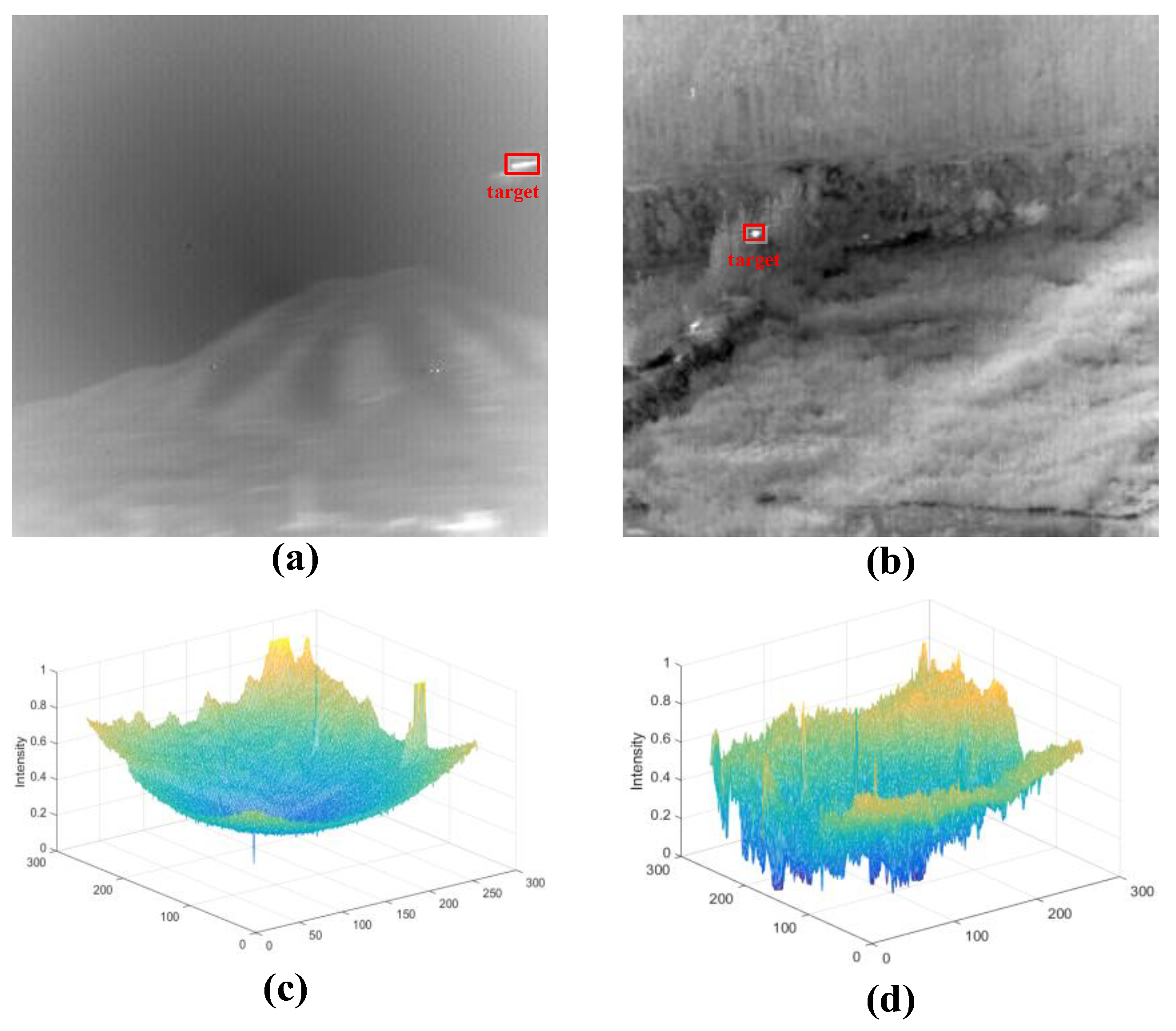
Figure 1, unmanned aerial vehicle (UAV) objects in infrared images may take up only several pixels, with little structural or texture information because they are far from the imaging sensor [
7,
8]; thus, they may reduce the detection robustness. Moreover, complex backgrounds, such as cloud clutter and sea clutter, may lead to low signal-to-clutter ratio (SCR) [
9,
10], which may increase the difficulty of detecting small objects in infrared images. For example, artificial heat sources and heavy clouds may increase the false-alarm rates [
11]. Therefore, detecting objects with infrared image sequences is still a difficult problem.
Infrared object-detection methods usually consist of single-frame-based methods and sequence-based methods according to the number of frames used for detecting objects in infrared images [
12]. Sequence-based methods including 3D matched filter [
13], dynamic programming [
14], pipeline filter [
15], and Kalman filter [
16], assume that the background is static between adjacent frames of the same image sequence. Nevertheless, the background usually changes rapidly in military applications because sensor platforms used for ISTS move fast even though the objects to be detected may remain static [
17]. Therefore, sequence-based approaches are unsuitable for potential applications. Single-frame-based methods that detect objects in each frame by exploring the consistency between background pixels are investigated because they can represent the background information more accurately.
The prior information is one of the most important components in single-frame-based infrared object-detection methods [
18]. The infrared object-detection approaches can be categorized into two types based on the type of prior information used, namely, local prior-based methods and nonlocal prior-based methods [
19].
Local prior-based approaches exploit a local background consistent prior that assumes the background is slowly transitional and close background pixels are highly correlated [
20]. However, real objects may break the local correlation hidden in the background pixels. Under this assumption, traditional local prior-based approaches include 2D least-mean-square filter [
21], morphological filter [
22], max-median filter [
23], and their improved methods. Unfortunately, traditional filters improve the edges of objects as well as the sky–sea surface or heavy cloud clutter because these background structures also break the local correlation. Approaches based on the saliency map that computes the difference between objects and their neighborhood have been proposed to better distinguish objects and background structures [
24]. Multiscale patch-based contrast measure [
25], local contrast measure (LCM) [
26], laplacian of Gaussian filter [
27], multiscale gray difference weighted image entropy [
28], nonnegativity constrained variational mode decomposition [
29], and saliency in the Fourier domain [
30] are used to obtain saliency maps. The local prior-based methods may suffer from a nonuniform or heterogeneous background that ruins the spatial consistency, thereby leading to a high false-alarm rate [
31].
Different from local priors, nonlocal priors explore the nonlocal self-correlation property of background patches by taking advantage of target sparsity and low-rank of background pixels in infrared images [
32]. Essentially, these types of methods model objects in infrared images as a sparse representation of the input data. A classical nonlocal prior-based approach called the infrared patch image (IPI) model [
33] is proposed by taking advantage of the nonlocal relation between background images. However, it suffers from over-shrinking of targets and noise residual due to the nuclear norm of the low-rank regularization term. Therefore, some improved versions of IPI are proposed by better reconstructing a low-rank matrix. The patch tensor model [
34] can explore the nonlocal information on the assumption of low-rank unfolding matrices. Dictionary learning and principal component pursuit approaches can separate the background and target matrix from the original image. However, they cannot effectively handle infrared images with complex background. Total variation should be combined with principal component pursuit to address this problem [
35]. However, the result may be a local minimum because it approximates the
[
36] that represents the total number of nonzero elements as the
[
37], representing the sum of the magnitudes. Moreover,
[
38] is used to optimize the infrared small-object detection approaches to better reach the global minimum [
39]. To accurately detect the small target located in a highly heterogeneous background, a low-rank and sparse representation model is proposed under the multi-subspace cluster assumption [
40]. The nonlocal priors are more powerful and fit the real scenes effectively, but still suffer from sparse edges and noise [
41]. Moreover, existing approaches are faced with two drawbacks, namely, target edges highlighted along with background edges, as shown in
Figure 2a, and no clear edges, as shown in
Figure 2b.
A novel infrared object-detection approach based on spatial–temporal patch tensor and object selection is proposed to fully use effective information in the temporal domain and to maintain a balance between the object-detection performance and computation time. Using the spatial–temporal patch tensor, color-boosted and object selection approach, UAV targets under sky or cloud background can be detected in target images reconstructed from original infrared images. The major contributions of this study are as follows:
The proposed framework is an unsupervised infrared object-detection method which can provide effective means for infrared small-object detection when no labeled information of true UAV targets is acquired.
The proposed spatial–temporal patch tensor can dig out the spatial and temporal evidence hidden in infrared image sequences by performing median pooling operations on three adjacent frames to further suppress the sky or cloud clutter and enable a better target-detection performance.
An object-selection approach is proposed to automatically extract objects from infrared images based on the cluster center derived from unsupervised clustering, which can decrease the search scope of objects and the false-alarm rates.
This paper is organized as follows.
Section 2 introduces the proposed framework for infrared small-object detection consisting of constructing spatial–temporal patch tensor, contrast-boosted, and object-selection approach. Then, the dataset description and experimental setup are depicted in
Section 3. Experimental results and their analysis are shown in
Section 4.
Section 5 concludes the study, and is then followed by future directions.
2. Materials and Methods
An unsupervised infrared UAV target-detection method based on spatial–temporal patch tensor and object selection is proposed in this study.
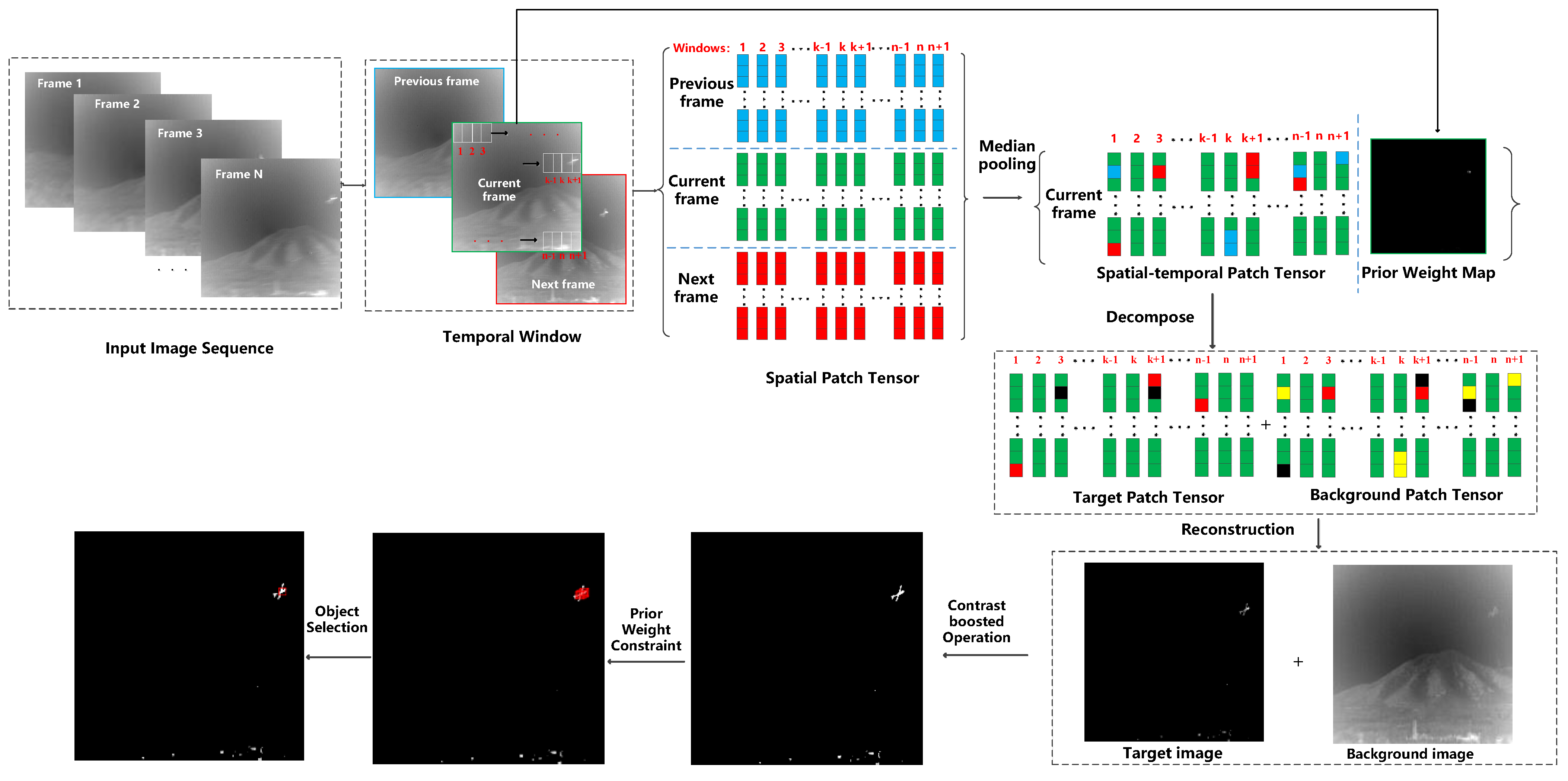
Figure 3 shows that the proposed method can be divided into the following steps.
Constructing spatial–temporal patch tensor for each frame of infrared image sequences. For each frame of the infrared image sequence, its temporal window is constructed with three adjacent frames. Patch tensor is constructed for each frame of the temporal window with t sliding windows whose size is . Median pooling is applied to the patch tensor of all frames in the temporal window to obtain the spatial–temporal patch tensor .
Calculating prior weight map and its patch tensor. The prior weight maps that can reflect the background and object information in infrared images to some extent are calculated for each temporal frame by combining local and nonlocal priors. Patch tensor of prior weight map is constructed for each temporal frame with t sliding windows with a size of .
Decomposing background and target patch tensor from the spatial–temporal patch tensor and patch tensor of prior weight map . The patch tensor of temporal frame is separated into a sparse patch tensor and a low-rank patch tensor with the constraint of , which can be considered a target and background patch tensor.
Reconstructing background and target images from background and target patch tensors. Background image and target image are reconstructed from the background patch tensor and target patch tensor .
Performing the proposed contrast-boosted method on reconstructed target images. To enhance the contrast between gray values of background pixels and target pixels, the contrast-boosted approach that combines Tophat operations with Bothat operations are performed on reconstructed target images to obtain enhanced target images.
Segmenting UAV targets from the enhanced target images by the object-selection approach based on the cluster center. Candidate pixels that satisfy the threshold of prior weight map are obtained for each frame. Then, the object-selection approach is proposed to determine the optimal object number by clustering the candidate object pixels. Each cluster center is considered a detected object.
2.1. Construction of Spatial–Temporal Patch Tensor and Prior Weight Map
Construction of spatial–temporal patch tensor: The existing infrared object-detection methods are usually based on the spatial patch tensor, which may ignore the temporal information hidden in infrared image sequences. Therefore, a spatial–temporal patch tensor is proposed to solve this problem.
The main idea of spatial–temporal patch tensor is shown in
Figure 4. Given an infrared image sequence consisting of three frames
in a sliding window
, a temporal window is initially constructed for each frame, namely,
. Then, a spatial patch tensor is constructed for each frame of the temporal window. Finally, median pooling is performed on all spatial patch tensors to obtain the spatial–temporal patch tensor.
The idea of constructing a spatial patch tensor should be explained prior to illustrating a spatial–temporal patch tensor. Overlapped local patches may contain spatial information hidden in pixels because different patches may include the same pixel in one image. Therefore, a spatial patch tensor from generated overlapped local patches in infrared images is constructed. The procedure can be illustrated as follows. Initially, overlapped local patches are generated from left to right and top to bottom in each frame of infrared image sequences. Then, gray values of each pixel in the overlapped local patches are vectorized as a column of a tensor. Finally, vectors of all local patches in the frame form the spatial patch tensor.
The details of constructing a spatial–temporal patch tensor can be illustrated as follows. A temporal window
is constructed for frame
to fully use the temporal information. For each frame in the temporal windows, spatial patch tensors
are constructed. Three patch tensors in the temporal window that are generated by the local patch located in the same place of image are highly correlated because adjacent frames are usually highly correlated in image sequences. Therefore, the spatial patch tensors in the temporal may be redundant. To reduce the redundancy of the spatial patch tensor and fully use temporal information, median pooling is performed on three spatial patch tensors, as shown in Equation (1), as follows:
where the median value of corresponding elements of three spatial patch tensors is considered the value of the spatial–temporal patch tensor.
The size of the spatial–temporal patch tensor is the same as that of the spatial patch tensor for each frame but with richer temporal information. The spatial–temporal patch tensor can enrich the temporal information and better represent each frame of infrared image sequences.
Construction of prior weight map: Existing prior weight-based methods use structure tensors [
42] to distinguish between image boundaries and real objects. Structure tensors are widely used in many partial differential equation (PDE)-based methods [
43] to estimate the local structure information in the image, including edge orientation. To integrate the local information, the structure tensor is constructed based on a local regularization of a tensorial product, which is defined in Equation (2), as follows:
where
is a Gaussian-smoothed version of a given image
I.
is the standard deviation of the Gaussian kernel; it denotes the noise scale, making the edge detector ignorant of small details.
is a symmetric and positive semi-definite matrix.
Two highest eigenvalues
and
of the structure tensor can be used as two feature descriptors of the local geometry structure, which can be calculated as Equation (3).
A combination of eigenvalues can enhance image boundaries, which can distinguish image boundaries similar to those of targets. The existing local prior is designed in Equation (4).
where
and
can be calculated by applying Equations (2) and (3) to every pixel in the input image
I,
h is a weight-stretching parameter,
and
are the maximum and minimum of eigenvectors
and
, respectively.
However, operator cannot identify whether image boundaries are background or targets. As a result, objects located at corner regions disappear or over-shrink.
To address these problems, the prior weight map
improves the corner strength function
[
44], as shown in Equations (5) and (6).
where
represents the location of pixel. The prior weight map
consists of two parts. The first part
replaces the
operator with the maximum operator
to suppress the problem in the
operator to some extent. In the second part,
and
denote the trace and determinant of the structure tensor, respectively. The second part, namely,
can not only highlight object information as expected, but also identify the objects located at corner regions.
Then, the prior weight map
is normalized with Equation (7).
where
and
represent the minimum and the maximum of the prior weight map
, respectively.
2.2. Reconstructing Background and Target Images from Spatial–Temporal Patch Tensor
Reconstructing background and target patch tensor: Existing methods impose tensor robust principal component analysis [
45] to separate sparse and low-rank tensors, as shown in Equation (8).
where
D,
B and
T represent the input, background, and target patch tensor, respectively;
represents the tradeoff parameter between the background patch tensor and target patch tensor.
represents the number of nonzero elements. However, the low-rank of tensors cannot be evaluated in a mathematical approach.
To approximate the rank of the patch tensor more accurately and to incorporate prior information into the model that separates low-rank and sparse matrices, the objective function is modified in Equation (9), as follows:
where
represents the Hadamard product [
46], and
represents the sum of absolute values of all elements in the tensor. Each element in
represents the reciprocals of the corresponding element in
.
N represents the preserved target rank, and
is the
i-th largest singular value of
B. The objective function Equation (9) can be solved with alternating direction method of multiplier (ADMM) solver [
47] whose procedure is shown in Algorithm 1.
| Algorithm 1.ADMM solver |
| Input: Patch tensor of original image D, prior weight map , tradeoff parameter , penalty factor , preserved target rank N, stopping threshold , and learning rate of penalty factor . |
| Output: Patch tensor of target and background images and . |
| Initialize: = = 0, , , k = 0. |
| (1) Calculate the Langrangian function of Equations (9) with Equation (10).
where represents the langrangian multiplier. is the inner product of two tensors and is the Frobenius norm.
|
| (2) While not end of convergence do |
| (3) Calculate when fixing other parameters by solving Equation (11).
|
| (4) Calculate when fixing other parameters by solving Equation (12).
|
| (5) Calculate and with Equations (13) and (14), respectively.
|
| (6) Check the stopping criterion shown in Equation (15).
|
| (7) k = k + 1 |
| (8) End while |
| (9) Return: background and target patch tensor and |
As shown in
Figure 5, diverse types of patches may include the same pixel because local patches generated by the spatial patch tensor are usually overlapped. As a result, a pixel in infrared images may have several pixel values due to overlapped local patches. To determine pixel values from overlapped patches, a median function is introduced to reconstruct each pixel value as the median values of pixel values from overlapped patches, as shown in Equation (16).
where
and
are vectors including pixel gray values from
p local patches.
Contrast-boosted approach for target images: When reconstructing target and background images from original images, gray values of objects are lost in the background image to some extent because parts of objects are similar to the backgrounds. Therefore, target images should be enhanced in terms of the contrast between object and background to better distinguish between target and background pixels. Therefore, a contrast-boosted approach that combines Tophat [
48] with Bothat [
49] operations is proposed.
The contrast-boosted approach is performed to achieve an enhanced target image
, as shown in Equation (17), as follows:
where
and
can be computed as Equations (18) and (19).
where
b represents the structure elements,
represents the dilation operation, and
represents the erosion operation.
As shown in
Figure 6, the gray values of objects are improved after performing the contrast-boosted method shown in Equation (17) on target images. The enhanced target images can better distinguish between background pixels and object pixels, thereby decreasing the false-alarm rate.
2.3. Object-Selection Approach Based on the Cluster Center
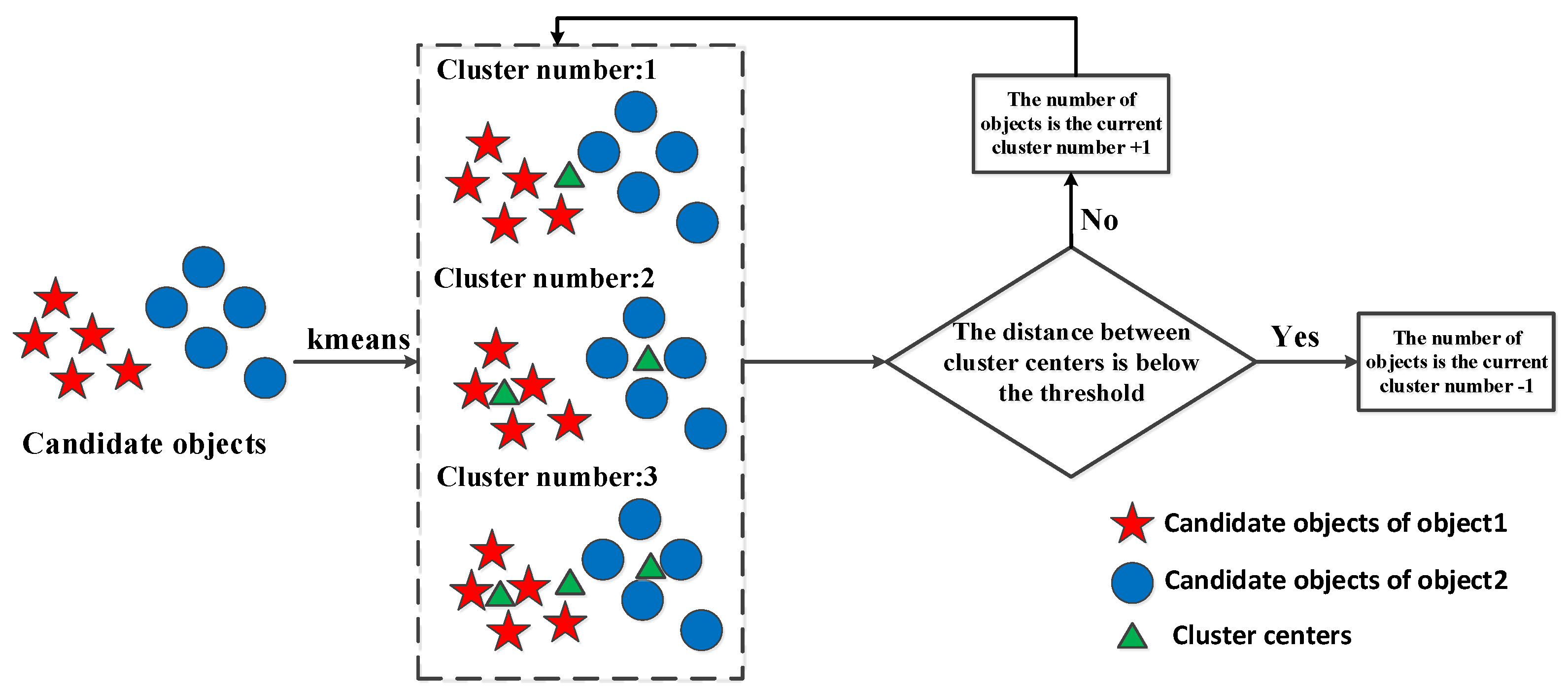
After obtaining enhanced target images, objects should be detected. When detecting objects in target images, the number of objects should be determined. Therefore, an object-selection approach is proposed for improving target images based on the cluster center derived from clustering locations and gray values. The main idea of determining the optimal number of objects is shown in
Figure 7. The object selection approach can be divided into the following steps:
A predefined threshold is used to select candidate object pixels because the prior weight maps calculated can reflect the possibility that one pixel belongs to the target.
Then, the optimal number of objects is determined by clustering candidate object pixels in terms of locations and gray values with k-means based on the assumption that close candidate object pixels are likely to belong to the same object. The procedure of determining the optimal number of objects is shown in Algorithm 2.
| Algorithm 2.Determination of optimal object number |
| Input: Locations and gray values of candidate objects and , the stopping threshold and . |
| Output: The optimal object number . |
| Initialize: Cluster number k = 1. |
| (1) Cluster locations and gray values of candidate object pixels with k-means and cluster number k, respectively. |
| (2) While not end of convergence do |
| (3) k = k + 1. |
| (4) Calculate the distance between each cluster center derived from clustering locations and locations, respectively, with Equations (20) and (21).
|
| where and represent the i-th cluster center derived from locations and gray values of candidate object pixels, respectively. |
| (5) Check the stopping criterion shown in Equation (22).
|
| (6) End while |
| (7) Return: optimal object number k − 1 |
Finally, cluster locations of candidate object pixels with the determined optimal object number. Each cluster is considered a detected object.
The object-selection approach can decrease the false-alarm rate and the search scope of objects to obtain satisfactory object-detection performance with relatively low computation time.
4. Discussion
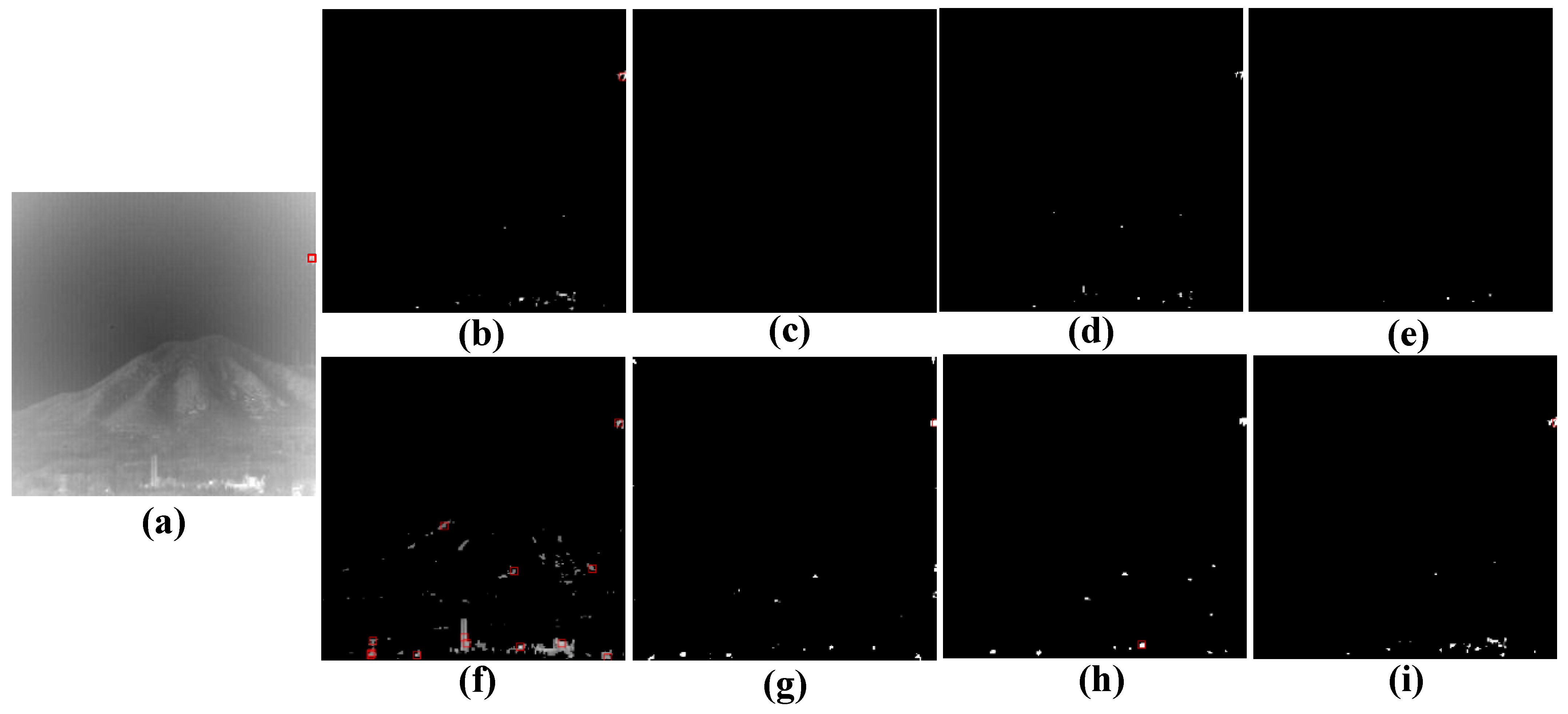
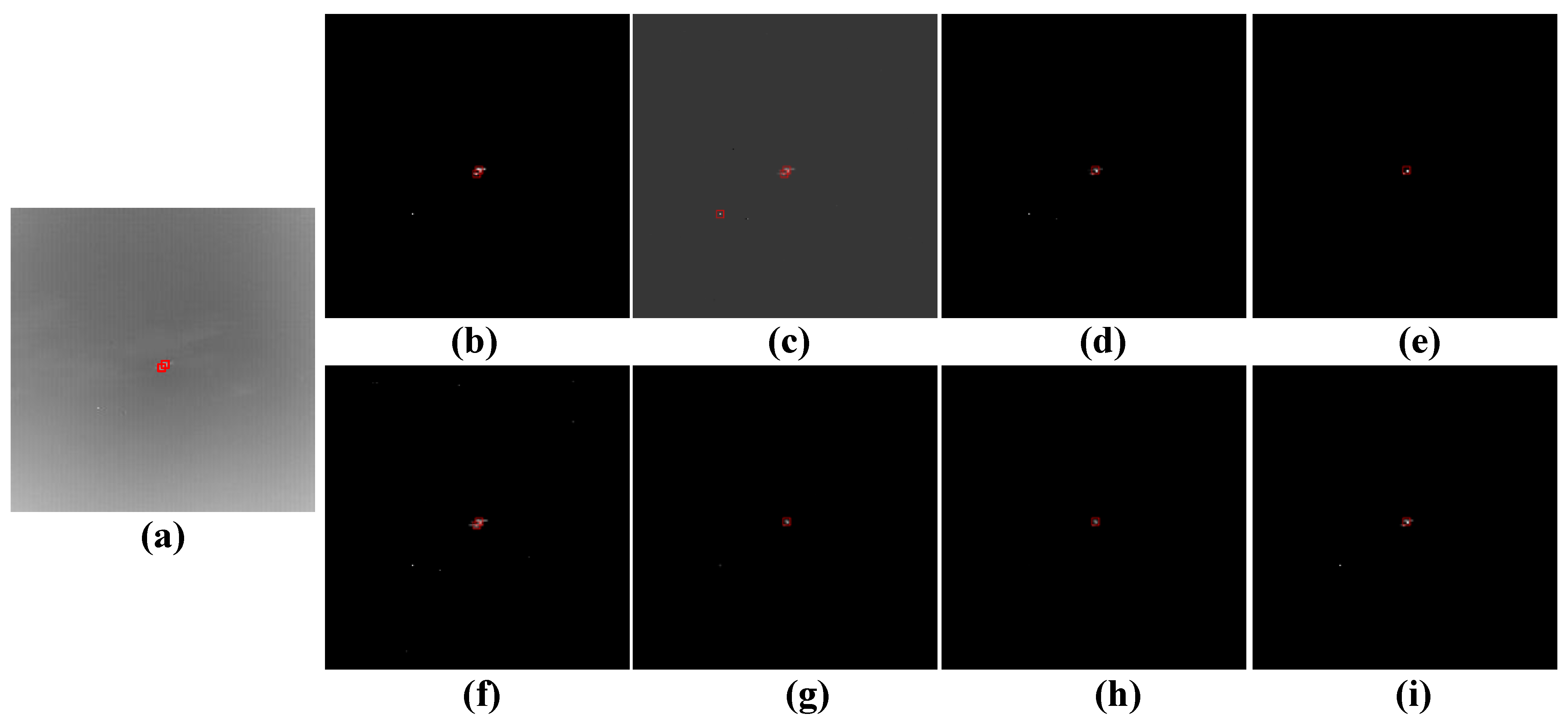
Figure 10 shows the performance comparison in the 27th frame of sequence 3 between the proposed framework and other existing methods. The proposed framework can detect the actual UAV objects because the contrast-boosted approach can enhance the object information when parts of object information are lacking.
Figure 9 shows that NRAM, IPI, GST, and WSLCM approaches fail to detect UAV targets because they cannot effectively handle scenes, where part of UAV targets is missing. TLLCM MOG and PSTNN approaches can detect UAV targets but the MOG algorithm detects some background pixels as objects.
Figure 11 shows the performance of the proposed framework in the 165th frame of sequence 4 compared with other existing infrared object-detection methods.
Figure 10 shows that the proposed framework can detect two true UAV targets because the object-selection approach can determine the number of objects accurately, even though two objects are close in images. NRAM, GST, TLLCM, WSLCM, and PSTNN approaches may miss one UAV target because two UAV targets are very close in the 165th frame. The proposed framework, MOG, and IPI approaches can accurately detect two UAV targets, whereas the IPI method detects one background object as object.
Figure 12 shows the performance of the proposed framework along with other existing infrared object detection approaches in the 28th frame of sequence 16.
Figure 11 shows that all methods including the proposed framework can detect true UAV targets because the background can be suppressed effectively in this scene. However, IPI, MOG, and PSTNN approaches detect some background pixels as objects because they do not suppress background information effectively.
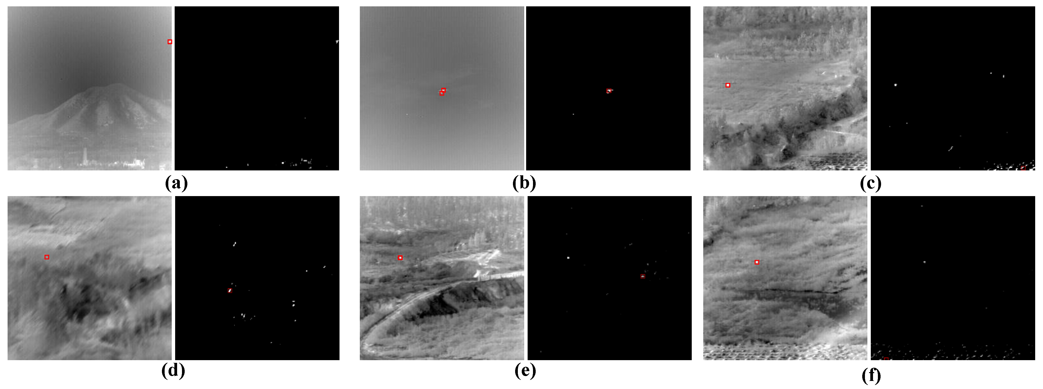
Figure 13 shows the error of the proposed framework in five sequences; it is caused by different reasons. For (a), part of UAV objects is missing, leading to incomplete object shape information. Objects of (b) are close in infrared images, which may lead to missing detection of UAV targets. For (c)–(f), objects and background are highly similar in gray values and may cause confusion between objects and background.
