1. Introduction
A wide array of both past and recent studies have highlighted that a diverse body of submesoscale and mesoscale phenomena, such as eddies, fronts, and vortex filaments, amongst others, are very active in and ubiquitous throughout the global ocean [
1,
2,
3]. Phillips [
4] and Mei [
5] recognized that these phenomena can induce strong variability in surface waves through wave–current interactions. Specifically, when waves interact with non-uniform currents, waves undergo changes in wave steepness, surface, roughness, and wave breaking in addition to the occurrence of extreme wave heights [
6,
7]. Crucial for this paper, mesoscale eddies have surface current velocities with a unique annular structure which can affect both wave properties and their energy distributions. Through the usage of field measurements and numerical models, the current effect on waves (CEW) has been rigorously explored.
Analyses of Synthetic Aperture Radar (SAR) imagery, satellite altimeter measurements, and airborne observations can be used to document the widespread effect of eddies on surface waves. For example, Antony et al. [
8] used SAR images to monitor the imprinting of a mesoscale eddy on a surface wave field in the Gulf of Alaska. Romero et al. [
3] used airborne observations to study and catalogue the effects of the Gulf Stream and a nearby eddy on local waves. It was identified that the nonlinear characteristics of the waves changed significantly after passing through the strong current, and wave breaking rates increased. Additionally, where waves and currents propagated/flowed opposite to one another, the significant wave height (
) could be modulated by 30%. Quilfen et al. [
9] used SAR and satellite altimeters to analyze the wave field across the Agulhas Current and found that although patterns identified in a wave model forced with altimeter-observed surface currents were consistent with SAR measurements, the CEWs were under-predicted.
Numerical simulations into CEW have also been extensively conducted. Recently, Ardhuin et al. [
2] used satellite altimetry alongside numerical models to show that the modulation of the wave field by currents occurs at scales of 10–100 km, with
varying by more than 50% on scales of 10 km. Romero et al. [
10] presented a numerical study of CEW on the submesoscales (on the order of hundreds to tens of kilometers) with a realistic model configuration in Southern California. There it was identified that the modulation of wave field due to currents is larger for the wave-breaking variables (i.e., whitecap coverage, air-entrainment, and energy dissipation), followed by the resolved mean square slope, surface Stokes drift, and
. Background currents on average increased the directional spreading by 0.9° and modulated the mean wave direction within ±5°. Villas Bôas et al. [
11] used the WaveWatch III (WWIII) third-generation numerical wave model to assess the relative effect of current divergence and vorticity in modifying several wave properties, including wave direction, period, directional spreading, and
. The authors found that the spatial variability of
was highly sensitive to the nature of the underlying current, and that refraction is the primary mechanism that led to
gradients. Marechal et al. [
12] also used WWIII but studied the effect of wind waves within an eddy. There, they uncovered that wave amplitude, frequency, and direction were all sensitive to the presence of the underlying mesoscale structures which resulted from the destabilization of the eddy. Additionally, it was identified that the surface current vorticity and the intrinsic frequency of incident waves were key in the wave response to current modulation. Marechal and Ardhuin [
13] showed that a phase-averaged numerical wave model forced with surface winds, realistic and high-resolution surface currents that was sufficiently directionally discretized could capture the sharp
gradients observed by satellite altimeters.
To investigate CEWs within mesoscale eddies, this study selected an eddy in the South China Sea (SCS). As one of the largest semi-enclosed marginal seas of the Western North Pacific, the SCS is characterized by a highly complex current system and many thousands of ocean mesoscale eddies [
14,
15]. Consequently, a series of observations from the China–France Oceanographic SATellite (CFOSAT) and output from a third-generation numerical wave model, Simulating WAves Nearshore (SWAN), were used to catalogue and analyze how waves interact with mesoscale eddies. The remainder of this paper is structured as follows. The data and methodology are given in
Section 2. Sensitivity analyses of the effects of an ideal mesoscale eddy on surface waves is provided in
Section 3.
Section 4 and
Section 5 provide results of an analysis of surface wave fields in the SCS from CFOSAT observations, and a summary of this study, respectively.
3. Sensitivity Experiments
In this section, sensitivity experiments of ideal mesoscale eddies on waves are carried out using SWAN. An eddy with different surface current velocities and a wave field forced by different wind speeds to generate waves of different heights are used to analyze the modulatory effect of eddies on waves.
3.1. Model Description
The SWAN model version 41.10 was used to simulate the wave characteristics in different cases. The SWAN model is a third-generation wave model based on the action density balance equation, which is widely applied to simulate wave parameters in coastal areas, lakes, and estuaries [
23,
24]. The governing equation is as follows:
where
is the evolution of the action density in space (
), time
, frequency (
) and propagation direction (
).
is defined as
and is conserved during propagation in the presence of ambient current, whereas energy density
is not. The quantities
and
are the propagation velocities in spectral space
. The ambient current is denoted as
.
on the right side of the equation represents the source function term that controls physical processes. The source term
is expressed as:
where
is the wind energy input, the nonlinear wave–wave interaction includes three-wave interactions (
) and four-wave interactions (
), which play a major role in shallow and deep water, respectively. The dissipation terms include whitecapping (
, bottom friction
, and depth-induced wave breaking (
. A detailed description concerning SWAN can be found in the official manual available at
http://swanmodel.sourceforge.net/ (accessed on 1 June 2021). In this study, wind energy input (
), four-wave interactions (
), and whitecapping (
were included for simulations. Three-wave interactions (
), bottom friction
, and depth-induced wave breaking (
were not considered.
3.2. Model Configuration
According to wave propagation theory, waves are dispersive in deep water and propagate with currents at the group velocity [
12]. CEW depends on the ratio of wave group velocity (
) to current velocity. Therefore, to study the factors affecting the CEW and how CEW contributes to wave evolution, sensitivity analyses of the eddy current velocity and overlying wind speed were carried out by using a set of experiments (
Table 1). The maximum eddy surface current velocities (U) were set to 0.2, 0.5, 0.8, and 1.0 m/s. The wind speed (W) was set to 5, 10, 15, 20 m/s. The initial spectrum peak periods were 2.23, 3.71, 5.02, and 6.13 s under the various wind speeds without currents. The corresponding wave phase velocities (
) were 3.38, 5.79, 7.83, 9.56 m/s. Changes in the wave age (
) and the ratio of wave group to current velocity (
) are discussed.
The SWAN wave model was run in nonstationary mode. By default, the initial condition is the JONSWAP spectrum with a
directional distribution centered around the local wind direction. As previously described, only wind energy input (
), four-wave interaction (
), and whitecapping (
were considered in the simulation. Four-wave interactions were estimated by the Discrete Interaction Approximation (DIA) where λ = 0.25 and Cnl4 = 3 × 10
7 [
25]. The whitecapping expression by Janssen was used [
26,
27]. Partially modeled diffraction was added to the model using a phase-decoupled refraction diffraction approach [
28].
In all tests, the eddy position was set in the middle of the region. The ideal center velocity and peripheral velocity of eddy were both 0 m/s. Let the point denoted by
be the eddy center.
is the distance from any point to the eddy center:
Setting , is eddy radius. In the simulation, .
The eddy surface velocity is given by:
The eddy surface current velocity varies with the distance from the eddy center. The current velocity within
from the eddy center increases continuously and decreases from
to
. The maximum velocity is at the location of
. The velocity outside
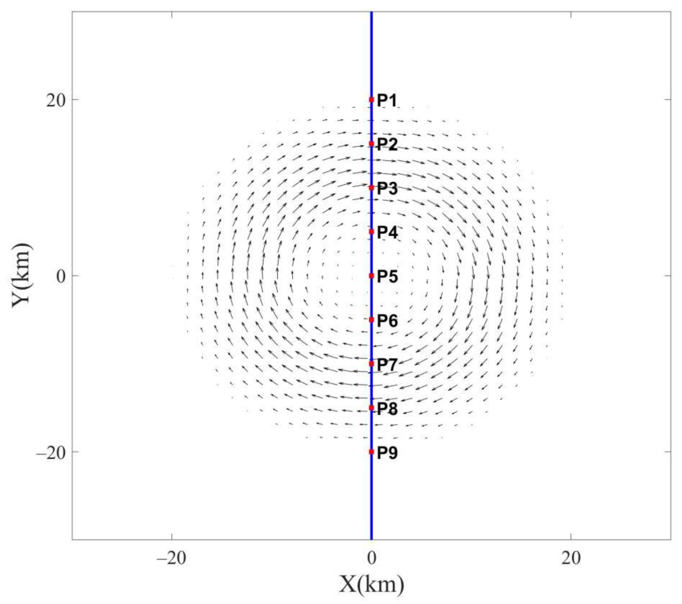
is 0 m/s. The maximum velocity is adjusted by changing parameter A. In the experiments, a clockwise-rotating anticyclonic eddy in the northern hemisphere was used as an example. The eddy radius was set to 20 km and wind direction was from west to east. The eddy velocity distribution estimated by Equation (4) is provided schematically in
Figure 2.
The parameter settings of the SWAN model were as follows. Calculations were performed on a Cartesian grid of 100 km × 100 km. The grid spatial resolution was 100 m × 100 m. The number of grid points was 1000 × 1000. The model was run for two days with a time step of 2 min. The directional wave energy density spectrum function was discretized using 24 directional bins and 32 frequency bins between 0.0418 Hz and 1.0 Hz. Other parameter settings are shown in
Table 2. In each test, wave trains propagated from the western boundary, generated by western, constant winds at the various wind speeds. The water depth (bathymetry) was set to 1000 m in all cases. To analyze the effect of eddies, model runs were performed with and without currents added.
3.3. Wave Field Variability in an Idealized Eddy
The variability of incident waves generated by different wind speeds following propagation into eddies with different current velocities is investigated in this section. Waves were dispersive in deep water and were propagating in the current at the group velocity (). CEW depended on the ratio of wave group velocity to current velocity. Surface currents modulated wave fields in terms of , peak wave direction (), mean wave period (), and average wave steepness (, the ratio of to L). The response of these wave parameters under different eddies are described below.
3.3.1. Significant Wave Height
Surface currents induce strong variability in
, and this is especially significant in highly solenoidal current fields such as those found in eddies [
13]. Results for changes in
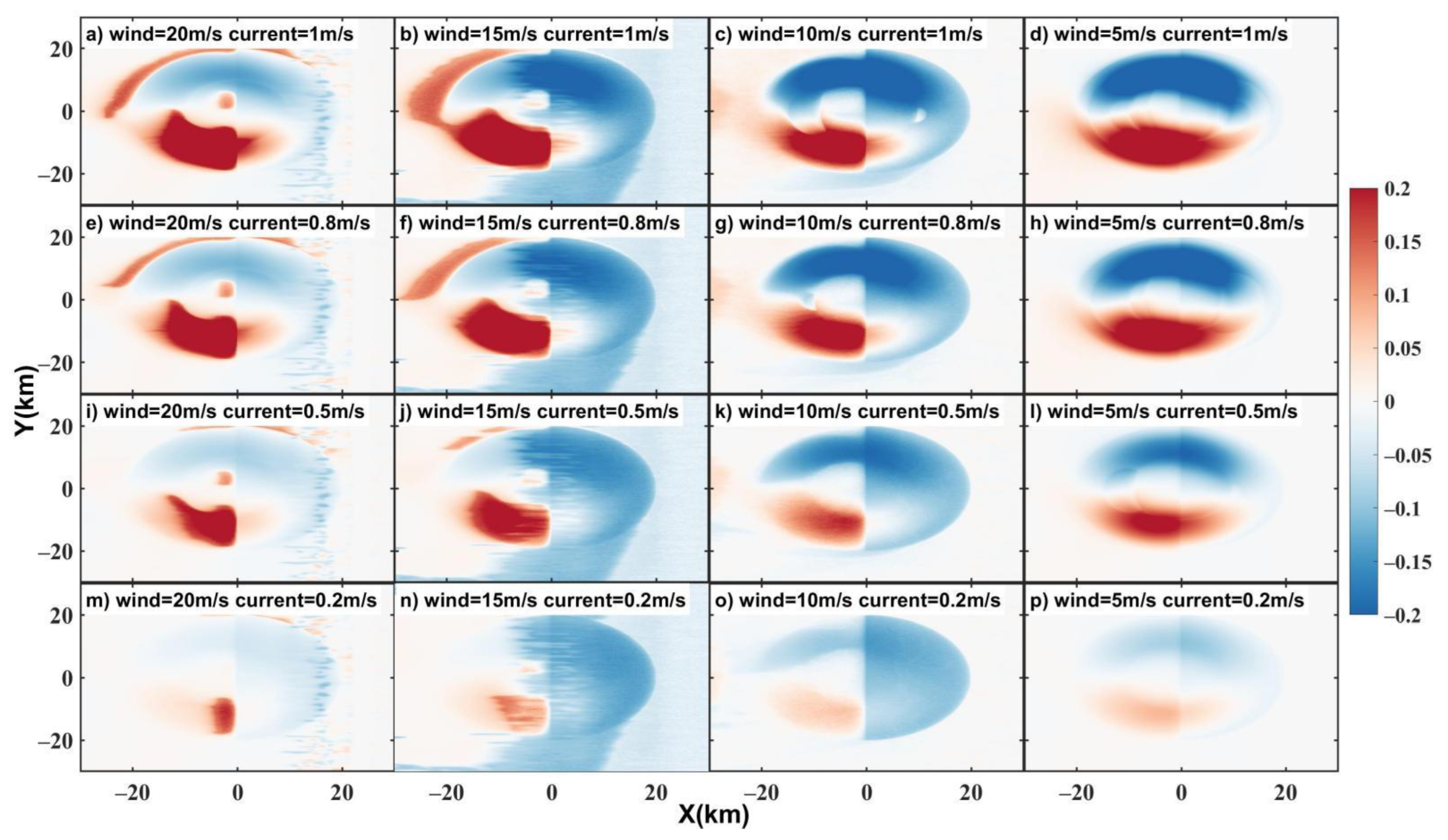
under the sixteen cases (
Table 1) are presented in
Figure 3. Model runs without currents added are also given for ease of comparison. Shadings given relative differences are estimated as the subtraction of modeled results without currents from those with currents. Relative differences are the ratios of the differences to the results without current. The most readily observable characteristic was the asymmetrical distribution of wave variability (
Figure 3a–d). A dipole-like structure formed where in the upper region demarcated by Y = 50–70 km
decreased but was accompanied by a simultaneous increase in the lower region (Y = 30–50 km). This occurred because the angle between waves and currents (WCA) was less than 90° in the upper region, but larger than 90° in the lower region. This resulted in waves following the current (upper region) but opposing the current (lower region). CEW became more apparent as current velocities increased (
Figure 3d,h,l,p). Interestingly, when the wind speed decreased (
Figure 3a–d), CEW also became strong. This was due to the ratio of wave group velocity to the current velocity. The closer the ratio was to 1, the stronger the CEW and vice versa. Generally, the wave group velocity was much larger than the current velocity. When wind speeds were low, and wave heights were small; the closer the wave and current velocities were to one another, the stronger the CEWs (
Table 1, column 7). In column 6 of
Table 1, and
Figure 3a–d, it can be seen that the higher the wave age (and hence, the more mature the wave age), the stronger CEW was. In Case 4 when W was 5 m/s and U was 1 m/s, CEW reached its maximum value of 20%. It can also be observed in
Figure 3c,d,h,l that
increased in the outer age of the upper area where CEW values were negative (X = 50–70 km, Y = 50–70 km).
decreased in the lower area (X = 50–70 km, Y = 30–50 km). This result is consistent with Marechal et al.’s [
12] result.
3.3.2. Mean Wave Period
The distribution of T variability (
Figure 4) was nearly opposite of
(
Figure 3). That is, inverse to the
case, T increased in the upper part of the eddy (Y = 50–70 km), but decreased in the lower part (Y = 30–50 km). When wave and currents propagated/flowed in the same direction, both the wave velocity and L increased, leading to increased T and lower
. In counter-current regions, both wave velocity and L decreased, leading to smaller T and larger
. Variability in T was also influenced by
and
. When waves were mature (i.e., higher wave ages; Column 6,
Table 1), the relative differences in T were more readily observable (
Figure 4a–d). When Cp/W = 0.696 and Cg/U = 1.69 (Case 4), T was influenced by CEW the most (more than 20%).
3.3.3. Average Wave Steepness
Figure 5 shows snapshots of the relative differences for relative
differences. It was found that the distribution of
variation was similar to
(
Figure 3). When waves and current propagated against one another (Y = 30–50 km),
increased and T decreased (
Figure 4), which led to a shortened L. Therefore,
increased. Similarly, the wave steepness variation decreased at the upper part (Y = 50–70 km). Accordingly, when waves and current propagated against one another,
became higher and waves became steeper, which led to wave focusing. When waves and current propagated/flowed in the same direction,
became smaller and eventually flattened, leading to wave defocusing. Currents modified the
most strongly when wave age was larger, and the wave group velocity was close to current velocity (Case 4).
3.3.4. Peak Wave Direction
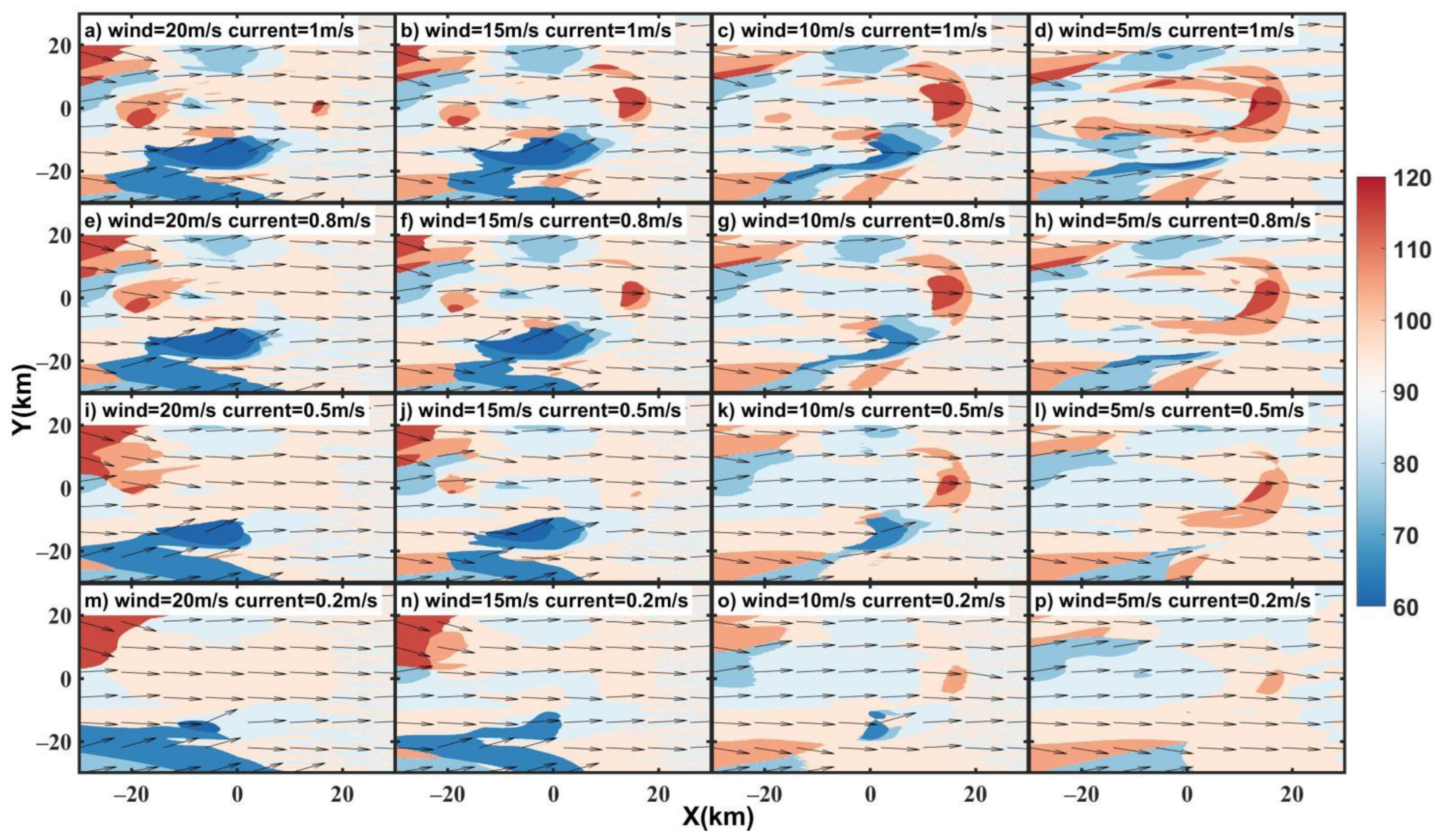
In each experiment, waves propagated west to east with an initial wave direction of 90° (0° is geographical north, rotating clockwise). The refraction induced by the surface currents could be captured by changes
. Due to refraction, waves turned within the current fields. In
Figure 6, it can be seen that at the upper part (WCA < 90°) of the eddy, the wave direction deflected northward towards the outer edge (i.e., Y = 60–70 km) and the wave direction angle decreased. In the inner area (i.e., Y = 50–60 km), an opposite change occurred. The wave direction was then southward. The different wave direction variation between Y = 60–70 km and Y = 50–60 km caused wave defocusing.
At the lower part (WCA > 90°), waves propagated northward and the wave direction angle decreased (Y = 20–40 km). This was especially the case at the eddy edge (Y = 30 km), which resulted in wave focusing. This trend was stronger when currents were faster. Changes in wave direction formed a dipole pattern. In addition, at the rear of the eddy tail (X = 60–70 km, Y = 50 km), the wave obviously propagated southward and the wave direction angle increased, just like the wake vortex. This trend was strongest when the CEW was strongest (Case 4). The variability in wave direction was almost 30°. Moreover, the larger the wave age, the more significant the changes in wave direction became (
Figure 6a–d). Mature waves were influenced by the CEW more strongly.
3.3.5. Statistical Analysis
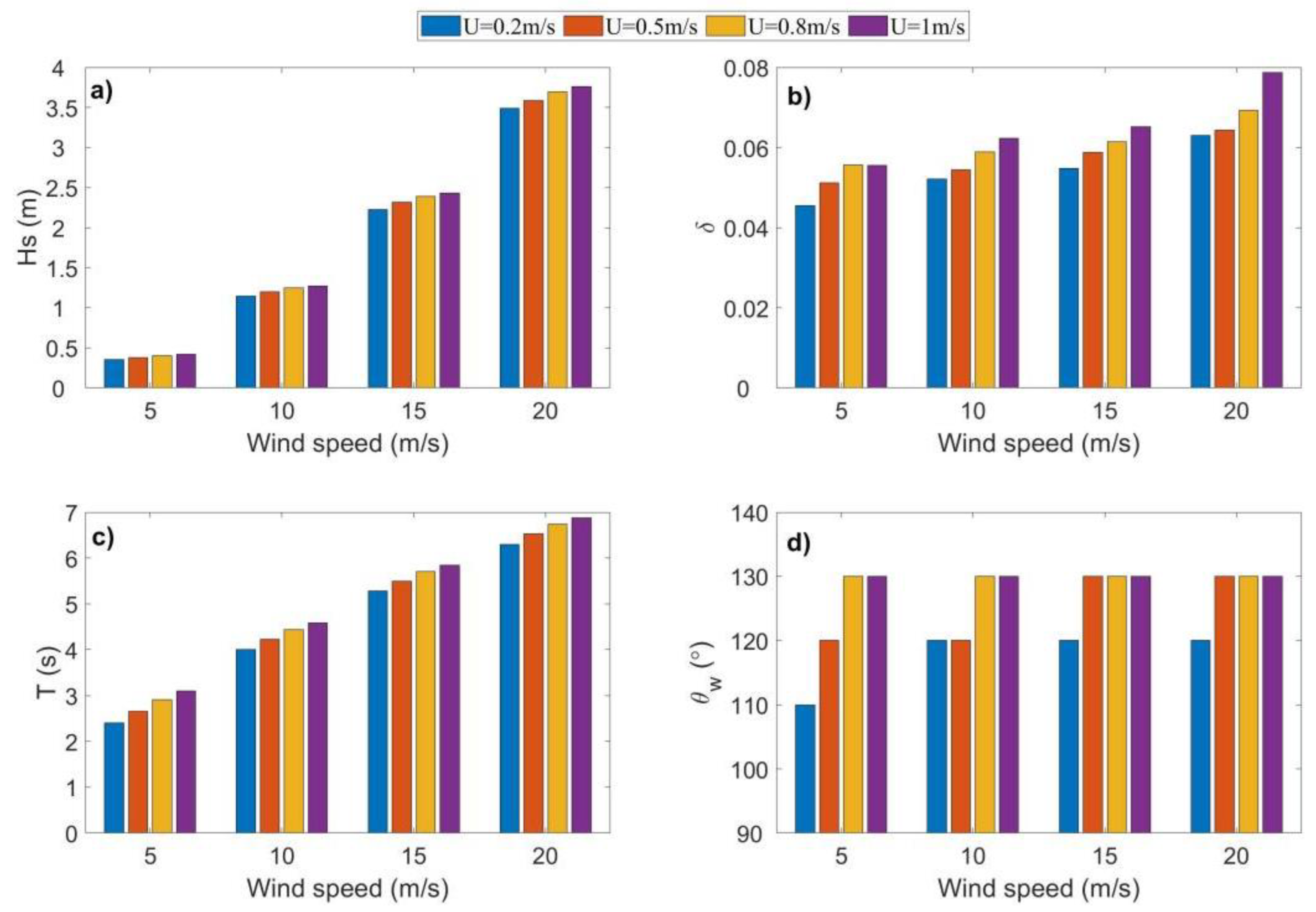
In order to analyze the proportion of the CEW to wave distribution, the maximum percentage variation of wave parameters under 16 cases is listed in
Table 3. Moreover, the maximum variation of simulated wave fields under 16 cases are plotted in
Figure 7. As shown in
Figure 7,
,
,
, and
all increased with W and U. It can be found in
Table 3 that the percentage variation of wave parameters caused by the CEW was the largest when the wind speed was 5 m/s and maximum eddy surface current velocity was 1 m/s (Case 4). In other words, Case 4 had the largest influence of CEW in all the experiments. The maximum percentage variability of
,
,
,
reached 30.31%, 35.02%, 41.01%, and 40°, respectively. Case 13 had the smallest percentage variation of the wave parameters. The corresponding variations of
,
,
,
were 4.90%, 11.03%, 3.55%, and 30°, respectively. This phenomenon reflected the CEW, which was mainly related to the ratio of wave group velocity to current velocity. The closer the two velocities, the larger the wave age, the greater the CEW, and vice versa.
In order to show the CEW to wave distribution more intuitively, the wave parameters of each point under Case 16 (
Figure 2; P1–P9) are drawn in
Figure 8. It can be seen that from P1 to P9, the wave height and average wave steepness reached the minimum at P3 (corresponding to the upper part of
Figure 3a and
Figure 5a) and the maximum at P7 (corresponding to the lower part of
Figure 3a and
Figure 5a), while the mean wave period changed in reverse. The peak wave direction became larger at P3 and smaller at P7, which corresponds to
Figure 6a. The analysis of wave distribution from the perspective of this section can deepen the understanding of wave field variations.
3.4. Spectral Analysis
In order to quantify the energy transport from ocean currents to waves, Ardhuin et al. [
2] used numerical models to simulate waves and currents in the Gulf Stream. There it was identified that the spectra of
and U showed that open ocean currents (eddies, fronts, and filaments) could be the main source of the variability in
at scales of 10–100 km. To study the energy transport between eddy and waves, spectral analysis was applied to
in all cases. The specific steps are described by Wang et al. [
29]. As shown in
Figure 9, wave spectra were quite different under different wind fields. When the wind speed was 5 m/s, the wave spectra under different current velocities had large differences, that is, U had a great influence on the wave energy distribution. When the wind speed was 20 m/s, the five spectra under different eddy surface current with 0, 0.2, 0.5, 0.8, and 1 m/s had little difference, which meant that the wave energy distribution was minutely affected by eddies. From
Figure 9a, it can be seen that the higher the current velocity, the higher the wave energy. The wave energy simulated with eddy’s maximum current velocity of 1 m/s was highest, followed by the simulation with eddy’s maximum current velocity of 0.8, 0.5, and 0.2 m/s. The minimum wave energy was estimated by the wave field simulated without current. The wave energy distribution caused by the eddy current mostly occurred in the spatial scale of 5–90 km, which belonged to the submesoscale and mesoscale eddies. The last oscillation when k ~ 0.5–8 km
−1 was probably related to the numerical dissipation.
5. Summary
A series of sensitivity experiments were carried out using a third-generation numerical wave model to investigate the effect of wind speed and eddy surface currents on CEW. The results showed that mesoscale eddies can affect wave heights, period, and steepness by 20–30%. Wave direction variability, by contrast, can range from 30°–40°. CEW was more noticeable with strong currents and weak winds, and was governed by wave age (
) and the ratio of wave group velocity to current velocity (
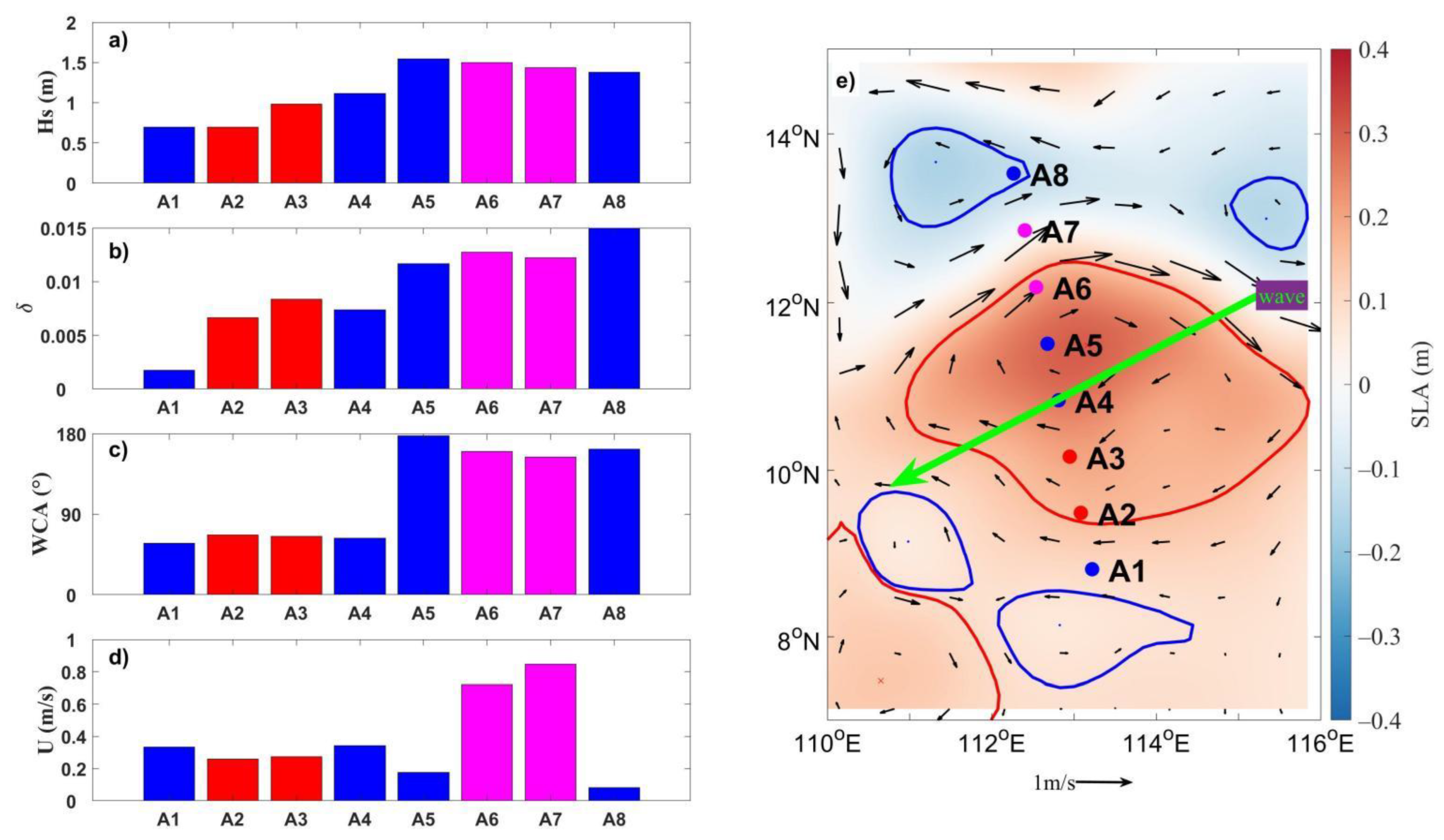
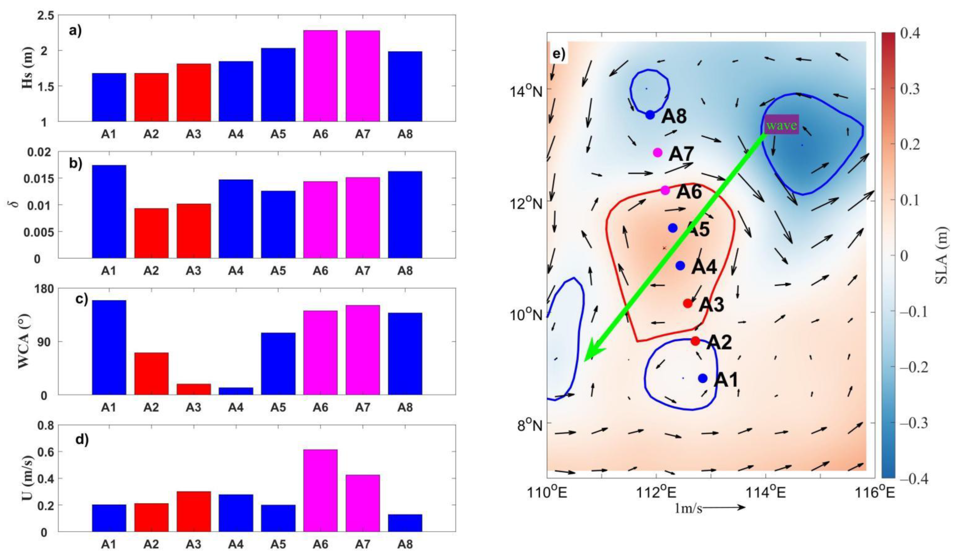
). Wave spectra clearly indicated that the wave energy distribution caused by current mostly happened in the spatial scale of 5–90 km, belonging to the sub-mesoscale and mesoscale. Using CFOSAT-SWIM observations, SWAN-suggested theoretical results were verified. That is, both wave height and steepness were significantly higher at A6 and A7 where WCA > 90° than A2 and A3 where WCA < 90°, which is consistent with the numerical model results. Finally, from the numerical model result and the CFOSAT-SWIM observation wave data, it could be found that along the direction of wave propagation, both wave height and the wave steepness increased on the right side of the anticyclonic eddy in the Northern Hemisphere, while they decreased on the left side (
Figure 13). It was identified that wave distribution differences on both sides of the eddy wave data track was perpendicular to the wave propagation direction. The method shown in this work provides a reference for investigating the effect of eddies on wave energy redistribution on a global scale.

