
The Impact of Systematic Attitude Error on the Measurement of Interferometric Radar Altimeter
 ,
,  ,
,
Abstract
1. Introduction
2. Theory of Coupling Attitude Altimetric Error of IRA
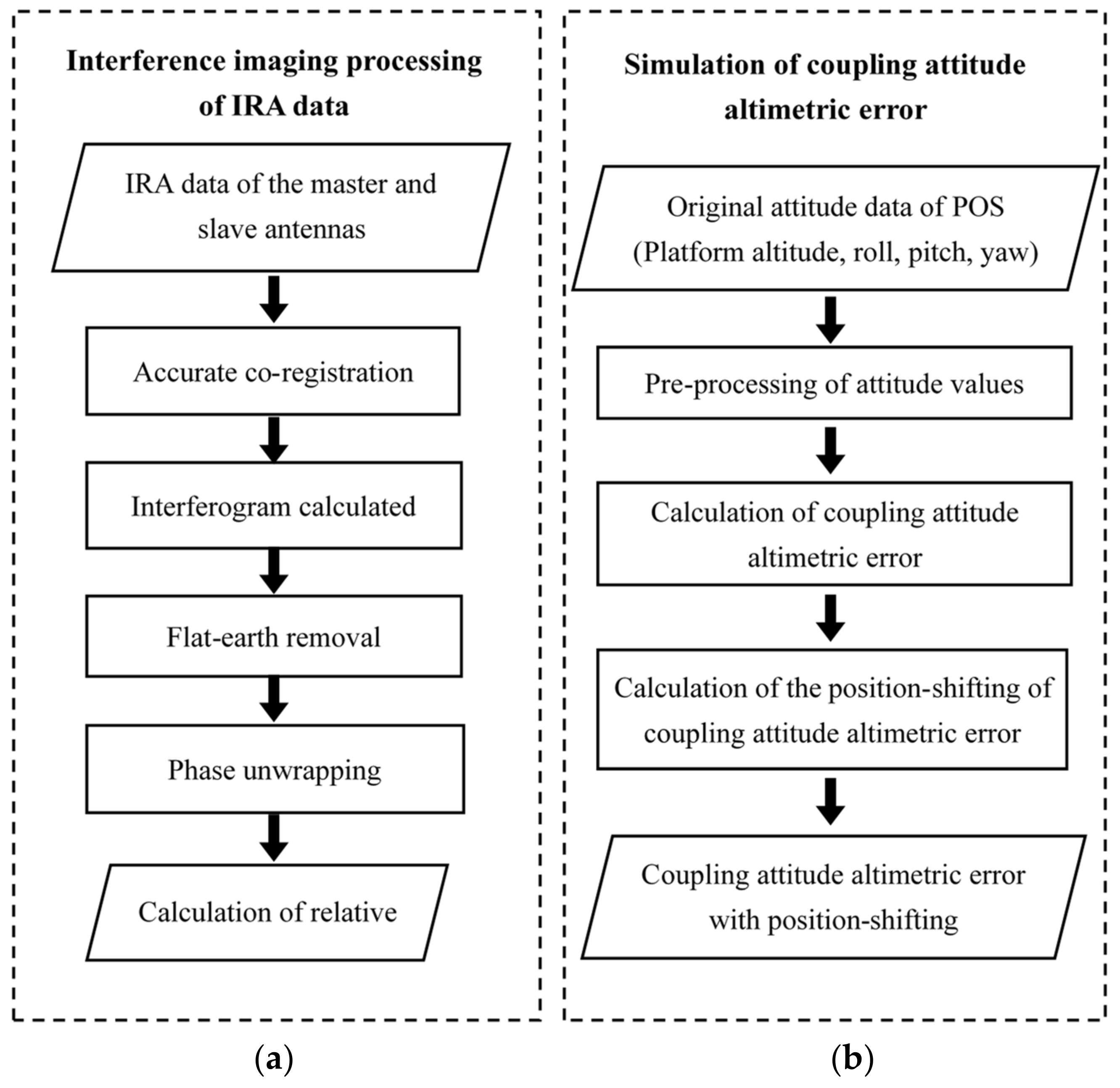
2.1. Coupling Attitude Altimetric Error
2.2. Independent Analysis of Attitude Errors
2.2.1. Platform Altitude Error
2.2.2. Roll Error
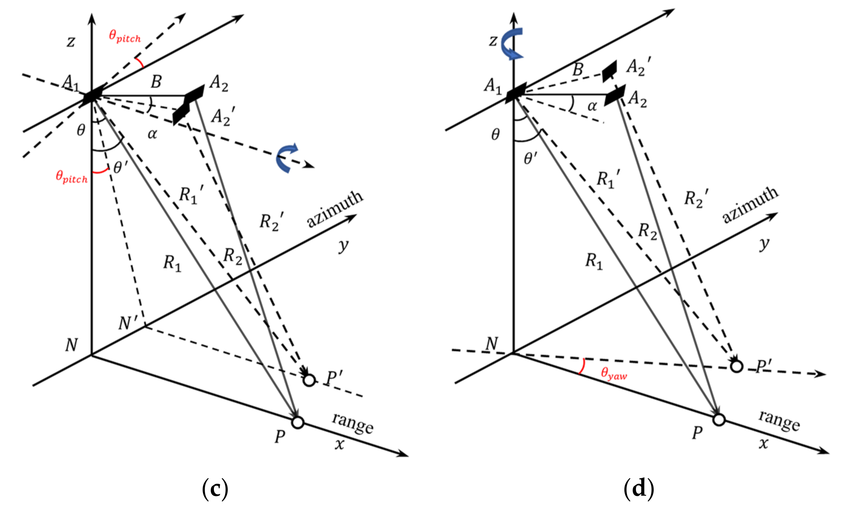
2.2.3. Pitch Error
2.2.4. Yaw Error
2.3. Position-Shifting of Altimetric Error
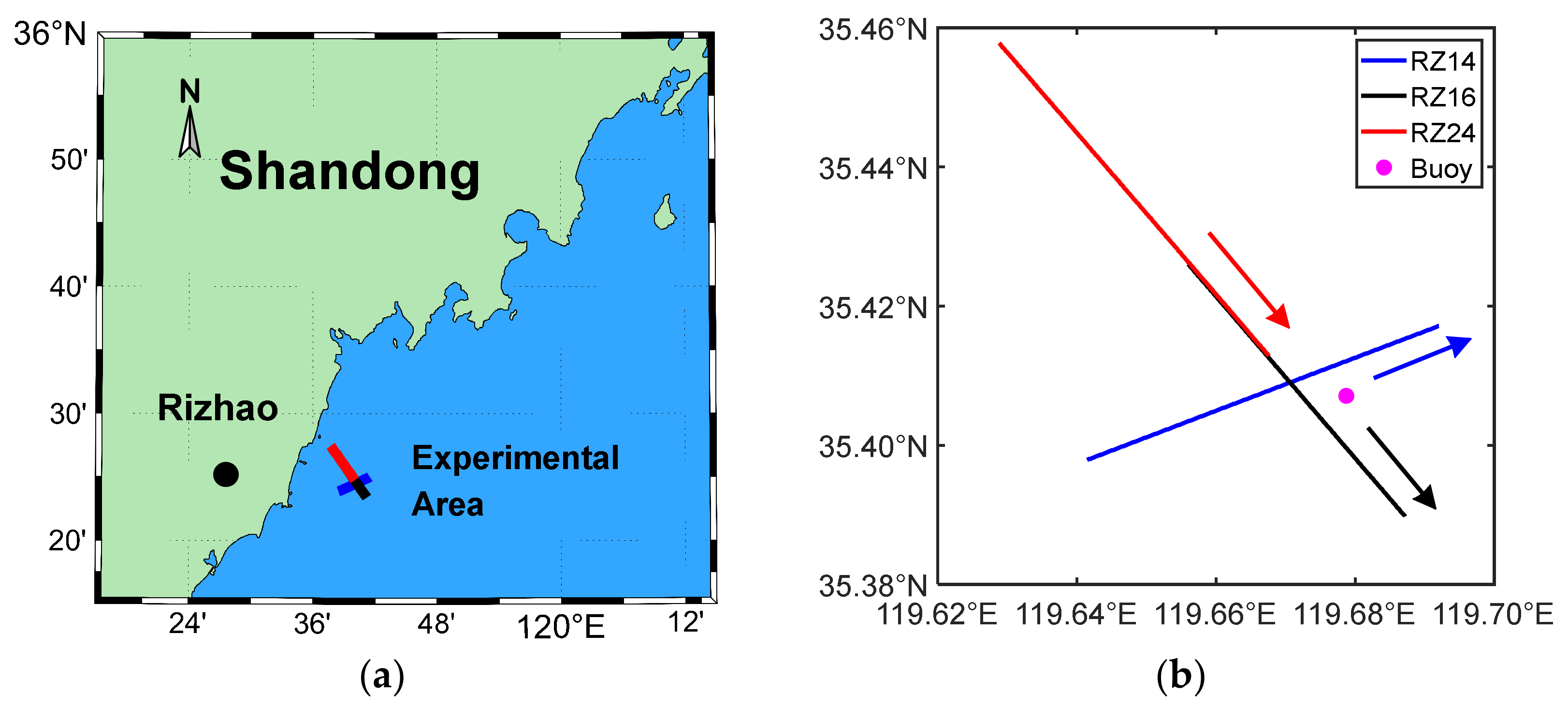
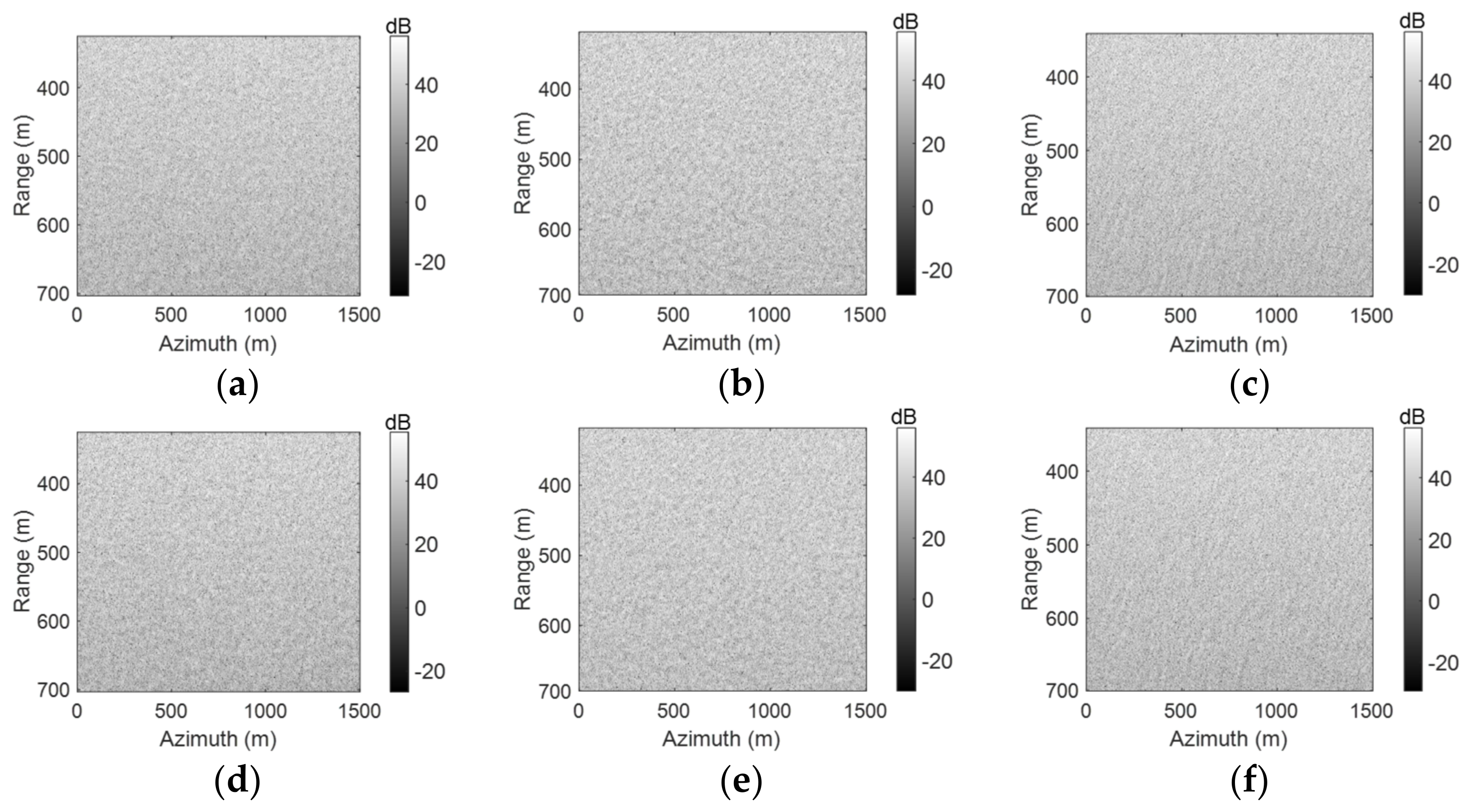
3. Simulation of Coupling Attitude Altimetric Error and Validation by Airborne IRA Experimental Data
4. Conclusions
Author Contributions
Funding
Data Availability Statement
Conflicts of Interest
References
- Rodriguez, E.; Pollard, D.; Martin, M. Wide-Swath Ocean Altimetry Using Radar Interferometry. IEEE Trans. Geosci. Remote Sens. 1999, 37, 624–626. Available online: https://dataverse.jpl.nasa.gov/dataset.xhtml?persistentId=hdl:2014/17962 (accessed on 23 October 2022).
- Fu, L.-L.; Chelton, D.B.; Le Traon, P.-Y.; Morrow, R. Eddy Dynamics from Satellite Altimetry. Oceanography 2010, 23, 14–25. [Google Scholar] [CrossRef]
- Fu, L.-L.; Alsdorf, D.; Rodriguez, E.; Morrow, R.; Mognard, N.; Lambin, J.; Vaze, P.; Lafon, T. The SWOT (Surface Water and Ocean Topography) Mission: Spaceborne Radar Interferometry for Oceanographic and Hydrological Applications. Proc. Oceanobs 2009, 9, 21–25. [Google Scholar]
- Esteban-Fernandez, D.; Fu, L.-L.; Rodriguez, E.; Brown, S.; Hodges, R. Ka-Band SAR Interferometry Studies for the SWOT Mission. In Proceedings of the 2010 IEEE International Geoscience and Remote Sensing Symposium, Honolulu, HI, USA, 25–30 July 2010; pp. 4401–4402. [Google Scholar] [CrossRef]
- Chen, G.; Tang, J.; Zhao, C.; Wu, S.; Yu, F.; Ma, C.; Xu, Y.; Chen, W.; Zhang, Y.; Liu, J.; et al. Concept Design of the “Guanlan” Science Mission: China’s Novel Contribution to Space Oceanography. Front. Mar. Sci. 2019, 6, 194. [Google Scholar] [CrossRef]
- Fu, L.-L.; Ubelmann, C. On the Transition from Profile Altimeter to Swath Altimeter for Observing Global Ocean Surface Topography. J. Atmos. Ocean. Technol. 2014, 31, 560–568. [Google Scholar] [CrossRef]
- Fjørtoft, R.; Koudogbo, F.; Duro, J.; Ruiz, C.; Gaudin, J.-M.; Mallet, A.; Pourthie, N.; Lion, C.; Ordoqui, P.; Arnaud, A. KaRIn on SWOT: Modeling and Simulation of Near-Nadir Ka-Band Interferometric SAR Images; SPIE: Toulouse, France, 2010; Volume 7826, pp. 306–314. [Google Scholar] [CrossRef]
- Fjortoft, R.; Gaudin, J.-M.; Pourthie, N.; Lalaurie, J.-C.; Mallet, A.; Nouvel, J.-F.; Martinot-Lagarde, J.; Oriot, H.; Borderies, P.; Ruiz, C.; et al. KaRIn on SWOT: Characteristics of Near-Nadir Ka-Band Interferometric SAR Imagery. IEEE Trans. Geosci. Remote Sens. 2014, 52, 2172–2185. [Google Scholar] [CrossRef]
- Parrinello, T.; Shepherd, A.; Bouffard, J.; Badessi, S.; Casal, T.; Davidson, M.; Fornari, M.; Maestroni, E.; Scagliola, M. CryoSat: ESA’s Ice Mission—Eight Years in Space. Adv. Space Res. 2018, 62, 1178–1190. [Google Scholar] [CrossRef]
- Gray, L.; Burgess, D.; Copland, L.; Cullen, R.; Galin, N.; Hawley, R.; Helm, V. Interferometric Swath Processing of Cryosat-2 Data for Glacial Ice Topography. Remote Sens. 2013, 7, 3133–3162. [Google Scholar] [CrossRef]
- Galin, N.; Wingham, D.J.; Cullen, R.; Francis, R.; Lawrence, I. Measuring the Pitch of CryoSat-2 Using the SAR Mode of the SIRAL Altimeter. IEEE Geosci. Remote Sens. Lett. 2014, 11, 1399–1403. [Google Scholar] [CrossRef]
- Gourmelen, N.; Escorihuela, M.J.; Shepherd, A.; Foresta, L.; Muir, A.; Garcia-Mondéjar, A.; Roca, M.; Baker, S.G.; Drinkwater, M.R. CryoSat-2 Swath Interferometric Altimetry for Mapping Ice Elevation and Elevation Change. Adv. Space Res. 2018, 62, 1226–1242. [Google Scholar] [CrossRef]
- Esteban Fernandez, D.; Pollard, B.; Vaze, P.; Abelson, R. SWOT Project Mission Performance and Error Budget. Jet Propuls. Lab. Doc. D-79084 Revis. A. 2017. Available online: https://swot.jpl.nasa.gov/system/documents/files/2178_2178_SWOT_D-79084_v10Y_FINAL_REVA__06082017.pdf (accessed on 23 October 2022).
- Rodriguez, E.; Pollard, B. Centimetric Sea Surface Height Accuracy Using the Wide-Swath Ocean Altimeter; IEEE: Toulouse, France, 2003; Volume 5, pp. 3011–3013. [Google Scholar] [CrossRef]
- Moccia, A.; Vetrella, S. A Tethered Interferometric Synthetic Aperture Radar (SAR) for a Topographic Mission. IEEE Trans. Geosci. Remote Sens. 1992, 30, 103–109. [Google Scholar] [CrossRef]
- Phalippou, L.; Guijarro, J. End to End Performances of a Short Baseline Interferometric Radar Altimeter for Ocean Mesoscale Topography; IEEE: Anchorage, AK, USA, 2004; Volume 2, pp. 765–768. [Google Scholar] [CrossRef]
- Rosen, P.A.; Hensley, S.; Joughin, I.R.; Li, F.K.; Madsen, S.N.; Rodriguez, E.; Goldstein, R.M. Synthetic Aperture Radar Interferometry. Proc. IEEE 2000, 88, 333–382. [Google Scholar] [CrossRef]
- Shao, Y.; Zhu, Z. Studies of Spaceborne Interferometric Synthetic Aperture Radars; SPIE: Barcelona, Spain, 1996; Volume 2757, pp. 443–449. [Google Scholar]
- Le Hénaff, M.; De Mey, P.; Mourre, B.; Le Traon, P.-Y. Contribution of a Wide-Swath Altimeter in a Shelf Seas Assimilation System: Impact of the Satellite Roll Errors. J. Atmos. Ocean. Technol. 2008, 25, 2133–2144. [Google Scholar] [CrossRef]
- Zhang, Y.; Zhai, W.; Gu, X.; Shi, X.; Kang, X. Experimental Demonstration for the Attitude Measurement Capability of Interferometric Radar Altimeter; Warsaw University of Technology (WUT): Gdansk, Poland, 2014; pp. 1–4. [Google Scholar] [CrossRef]
- Sun, D.; Wang, Y.; Bai, Y.; Zhang, Y. Ocean Waves Inversion Based on Airborne Radar Images with Small Incident Angle; IEEE: Hangzhou, China, 2020; pp. 1–4. [Google Scholar] [CrossRef]
- Sun, D.; Zhang, Y.; Wang, Y.; Chen, G.; Sun, H.; Yang, L.; Bai, Y.; Yu, F.; Zhao, C. Ocean Wave Inversion Based on Airborne IRA Images. IEEE Trans. Geosci. Remote Sens. 2021, 60, 1–13. [Google Scholar] [CrossRef]
- Mallorqui, J.J.; Bara, M.; Broquetas, A. Calibration Requirements for Airborne SAR Interferometry; SPIE: Barcelona, Spain, 2000; Volume 4173, pp. 267–278. [Google Scholar] [CrossRef]
- Gao, L.; Sun, H.; Qi, J.; Jiang, Q. Effect of Random Phase Error and Baseline Roll Angle Error on Eddy Identification by Interferometric Imaging Altimeter. J. Oceanol. Limnol. 2021, 40, 1881–1888. [Google Scholar] [CrossRef]
- Angino, G.; Impagnatiello, F.; Zelli, C. High Spatial Resolution Radar Altimetry for Global Earth Topography Mapping; IEEE: Singapore, 1997; Volume 1, pp. 15–17. [Google Scholar] [CrossRef]
- Fu, L.-L.; Alsdorf, D.; Morrow, R.; Rodriguez, E.; Mognard, N. SWOT: The Surface Water and Ocean Topography Mission: Wide-Swath Altimetric Elevation on Earth; Jet Propulsion Laboratory, National Aeronautics and Space Administration: Pasadena, CA, USA, 2012. Available online: https://dataverse.jpl.nasa.gov/dataset.xhtml?persistentId=hdl:2014/41996 (accessed on 23 October 2022).
- Galin, N.; Wingham, D.J.; Cullen, R.; Fornari, M.; Smith, W.H.F.; Abdalla, S. Calibration of the CryoSat-2 Interferometer and Measurement of Across-Track Ocean Slope. IEEE Trans. Geosci. Remote Sens. 2013, 51, 57–72. [Google Scholar] [CrossRef]
- Liu, B.; Zhang, R.; Wan, X.; Li, Y.; Yuan, S. Accuracy Analysis of Multi-base InSAR Altimeter in Ocean Surface Relative Elevation Measurement. J. Eng. 2019, 2019, 5789–5792. [Google Scholar] [CrossRef]
- Rodriguez, E.; Martin, J.M. Theory and Design of Interferometric Synthetic Aperture Radars. In IEE Proceedings F (Radar and Signal Processing); IET Digital Library: Stevenage, UK, 1992; Volume 139, pp. 147–159. [Google Scholar] [CrossRef]
- Enjolras, V.; Vincent, P.; Souyris, J.-C.; Rodriguez, E.; Phalippou, L.; Cazenave, A. Performances Study of Interferometric Radar Altimeters: From the Instrument to the Global Mission Definition. Sensors 2006, 6, 164–192. [Google Scholar] [CrossRef]
- Hanssen, R.F. Radar Interferometry: Data Interpretation and Error Analysis; Springer Science & Business Media: Berlin/Heidelberg, Germany, 2001; Volume 2. [Google Scholar]
- Kutoglu, H.S.; Mekik, C.; Akcin, H. A Comparison of Two Well Known Models for 7- Parameter Transformation. Aust. Surv. 2002, 47, 24–30. [Google Scholar] [CrossRef]
- Yang, L.; Xu, Y.; Zhou, X.; Zhu, L.; Jiang, Q.; Sun, H.; Chen, G.; Wang, P.; Mertikas, S.P.; Fu, Y.; et al. Calibration of an Airborne Interferometric Radar Altimeter over the Qingdao Coast Sea, China. Remote Sens. 2020, 12, 1651. [Google Scholar] [CrossRef]
- Birkett, C.M. Contribution of the TOPEX NASA Radar Altimeter to the Global Monitoring of Large Rivers and Wetlands. Water Resour. Res. 1998, 34, 1223–1239. [Google Scholar] [CrossRef]
- Wu, X.; Hensley, S.; Rodriguez, E.; Moller, D.; Muellerschoen, R.; Michel, T. Near Nadir Ka-Band Sar Interferometry: SWOT Airborne Experiment. In Proceedings of the 2011 IEEE International Geoscience and Remote Sensing Symposium, Vancouver, BC, Canada, 24–29 July 2011; pp. 2681–2684. [Google Scholar] [CrossRef]


| Parameters | Values |
|---|---|
| Center frequency | 35 GHz |
| Aircraft altitude | 3000 m |
| Azimuth resolution | 0.3 m |
| Slant-range resolution | 0.3 m |
| Beam width | 1.36 deg |
| Airborne velocity | 67 m/s (RZ14, RZ16) 83 m/s (RZ24) |
| Incidence angle | 1~15 deg |
| Baseline length | 0.3 m |
| Baseline orientation angle | −10 deg |
| Aircraft Heading angle | 16 deg (RZ14) 15 deg (RZ16) 17 deg (RZ24) |
| Parameters | Values |
|---|---|
| Aircraft altitude | 2~3 cm |
| Aircraft attitude angle | 0.003 deg |
| Aircraft velocity | 0.005 m/s |
| The Correlation Coefficients | RZ14 | RZ16 | RZ24 | |||
|---|---|---|---|---|---|---|
| At the nadir range (50 m) | 0.22 | 0.66 | 0.09 | 0.60 | 0.26 | 0.56 |
| At the middle range (350 m) | 0.39 | 0.73 | 0.30 | 0.63 | 0.37 | 0.50 |
| At the far range (700 m) | 0.19 | 0.87 | 0.04 | 0.68 | 0.34 | 0.80 |
Publisher’s Note: MDPI stays neutral with regard to jurisdictional claims in published maps and institutional affiliations. |
© 2022 by the authors. Licensee MDPI, Basel, Switzerland. This article is an open access article distributed under the terms and conditions of the Creative Commons Attribution (CC BY) license (https://creativecommons.org/licenses/by/4.0/).
Share and Cite
Tang, H.; Wang, Y.; Zhao, C.; Sun, D.; Chen, G.; Sun, H. The Impact of Systematic Attitude Error on the Measurement of Interferometric Radar Altimeter. Remote Sens. 2022, 14, 6028. https://doi.org/10.3390/rs14236028
Tang H, Wang Y, Zhao C, Sun D, Chen G, Sun H. The Impact of Systematic Attitude Error on the Measurement of Interferometric Radar Altimeter. Remote Sensing. 2022; 14(23):6028. https://doi.org/10.3390/rs14236028
Chicago/Turabian StyleTang, Haoyan, Yunhua Wang, Chaofang Zhao, Daozhong Sun, Ge Chen, and Hanwei Sun. 2022. "The Impact of Systematic Attitude Error on the Measurement of Interferometric Radar Altimeter" Remote Sensing 14, no. 23: 6028. https://doi.org/10.3390/rs14236028
APA StyleTang, H., Wang, Y., Zhao, C., Sun, D., Chen, G., & Sun, H. (2022). The Impact of Systematic Attitude Error on the Measurement of Interferometric Radar Altimeter. Remote Sensing, 14(23), 6028. https://doi.org/10.3390/rs14236028