Article

Nonlinear Ship Wake Detection in SAR Images Based on Electromagnetic Scattering Model and YOLOv5

School of Physics, Xidian University, Xi’an 710071, China
*
Author to whom correspondence should be addressed.
Remote Sens. 2022, 14(22), 5788; https://doi.org/10.3390/rs14225788
Submission received: 10 October 2022 / Revised: 10 November 2022 / Accepted: 12 November 2022 / Published: 16 November 2022

Abstract

:
Traditional wake detection methods have been successfully applied to the detection of a simple linear ship wake. However, they cannot effectively detect nonlinear wake and weak wake under high sea state conditions, whereas the deep-learning-based detection method could play to its strengths in this respect. Due to the lack of sufficient measured SAR images of ship wake to meet the training requirement for deep learning method, this paper explores the method to detect the nonlinear ship wake by combining electromagnetic scattering model with deep learning technique. The composite scene model of the sea surface and its wake is established first, then the facet scattering distribution of the ship wake and the sea background is analyzed with the help of the electromagnetic scattering model, and the simulation of the wake SAR images under the sea background is finally accomplished based on the modulation model. Combined with the simulation results and measured wake SAR images, the sample database is constructed. The You Only Look Once Version five algorithm (YOLOv5) based on deep learning techniques is applied to detect the wake target in complex conditions such as different sea states, multiple targets, curvilinear wakes, and weak wakes. The result show that the YOLOv5 leads to an obvious higher detection efficiency with satisfactory accuracy. Moreover, the comparison between YOLOv5 and the traditional Radon transform method for detecting nonlinear wakes in a strong noise background shows that the proposed method is better than the traditional object detection model. Thus, the proposed scheme would be a practical tool to deal with the detection of nonlinear ship wake and weak wake in complex scenarios, which will be helpful to the further remote sensing investigation of the ship.

Graphical Abstract

1. Introduction

Synthetic aperture radar (SAR) is an active microwave remote sensing technology that can measure the scattered wave from the target and reflect the physical characteristics of the target through data acquisition, data processing, as well as data analysis. SAR has become an important tool for observing the earth’s environment in recent years [1]. It is worth noting that SAR has all-day and all-weather imaging capabilities as well as the high-resolution feature, which has made it indispensable for monitoring natural and man-made hazards. Especially in the marine environment [2], SAR can be applied to wind and wave forecasting [3,4], oil spills and surfactant monitoring [5], target classification and detection [6,7,8,9], nearshore topography inversion [10], etc. The widespread use of SAR greatly promotes the development of related fields.
Although SAR technology has wide applications, it still faces many serious challenges. In the field of maritime target detection, the continuous improvement and development of stealth materials make it very difficult to directly observe ships using SAR. Moreover, targets at sea are so small in the ocean background that it is difficult to directly observe a ship with a low-resolution radar. In the case of high sea state conditions, the ship will be submerged in sea clutter, and the difficulty of ship detection will be further increased. Compared with the main structure of the ship, the features of the ship wake are relatively easier to distinguish because of their larger size and longer existence, and the parameters of the ship can be inverted once the information of the wake has been acquired [11]. How to efficiently and accurately identify the ship wake and how to apply it to engineering-related issues have come into focus recently.
Traditional wake detection methods, such as the Radon transform [12], Hough transform [13], etc., separated the target from the background of the wake based on the characteristic differences between the sea surface and the wake in the SAR image. Wang and Jin [14] proposed a wake detection method combining Radon transform and morphological-image processing techniques, which can better adapt to different noise environments and improve the applicability of Radon transform to detect wake. Karakuş et al. [15] put forward a sparse regularization-based method for detecting the wake of a ship, which can enhance the linear feature of the wake. Most of these studies only focused on the wake with linear features. When the nonlinear wake exists in a strong noise environment, preprocessing operations such as component separation of images, window segmentation, and simultaneous merging of small line detection would be required to detect the wakes; thus, these traditional approaches will show their limitations.
Compared to traditional methods, the deep learning method can not only extract low-dimensional features but also high-dimensional ones, which provides a good idea for complex wake detection research. Inspired by the basic idea of You Only Look Once (YOLO), an approach for detecting high-speed SAR ship images was put out by Zhang and Zhang [16]. Kang et al. [17] introduced a deep hierarchical network for SAR ship detection, that is, a contextual region-based Convolutional Neural Network (CNN) with multilayer fusion, which improved the detection performance for small ships. Kang and Kim [18] realized the recognition of ships by the CNN and the inversion of ship wakes. Graziano and Renga [19] used the deep learning algorithm to detect the wake information in SAR images. This method applied different CNN to test the Sentinel-1 images of high-flow offshore stations via a training set with more than 250 training samples, which effectively detected the wake without any prior knowledge or clues. Ma et al. [20] proposed an improved YOLO version three (YOLOv3), which had a stronger anti-noise ability, and the generalization ability of the model was clearly improved. Liu et al. [21] introduced a lightweight ship detection network based on the YOLO version four (YOLOv4)-LITE model to improve the accuracy and efficiency of multi-scale ship detection.
According to the above analysis, the combined application of the electromagnetic scattering approach and the deep learning method is performed in this paper to solve the problem of nonlinear wake and weak wake detection rather than to improve the deep learning method at the algorithmic level, which is the motivation of this paper. The main contribution and novelty of this paper are exhibited in the following two paragraphs:
  • For the purpose of detecting the nonlinear ship wake and weak wake in SAR images, the deep learning-based You Only Look Once Version five (YOLOv5) algorithm is used to improve the detection rate, which has a competitive generalization ability compared to other mainstream approaches [22];
  • In order to deal with the problem that the measured SAR wake image data sets are difficult to obtain and cannot meet the YOLOv5 training requirements, we consider combining a semi-deterministic facet scattering model and a bunching modulation model to simulate the ship wake SAR images. The joint use of the simulated SAR images and the acquired measured ship wake images enriches the sample set and lays a solid foundation for the nonlinear ship wake and weak wake detection based on YOLOv5.
The paper is organized as follows: Section 2 briefly presents the simulation theory of Kelvin ship wake and the sea surface. In Section 3, the detailed process for the electromagnetic scattering distribution of ship wake in marine scenes is provided. Section 4 mainly illustrates the simulation of the SAR image of a ship’s wake on the basis of electromagnetic scattering theory. The research on the proposed wake detection scheme is evaluated by real, measured SAR images, and the comparison between it and the traditional method is presented in Section 5. Section 6 is devoted to the conclusion of this paper. It should be noted that only the Kelvin wake pattern is focused on in this paper.
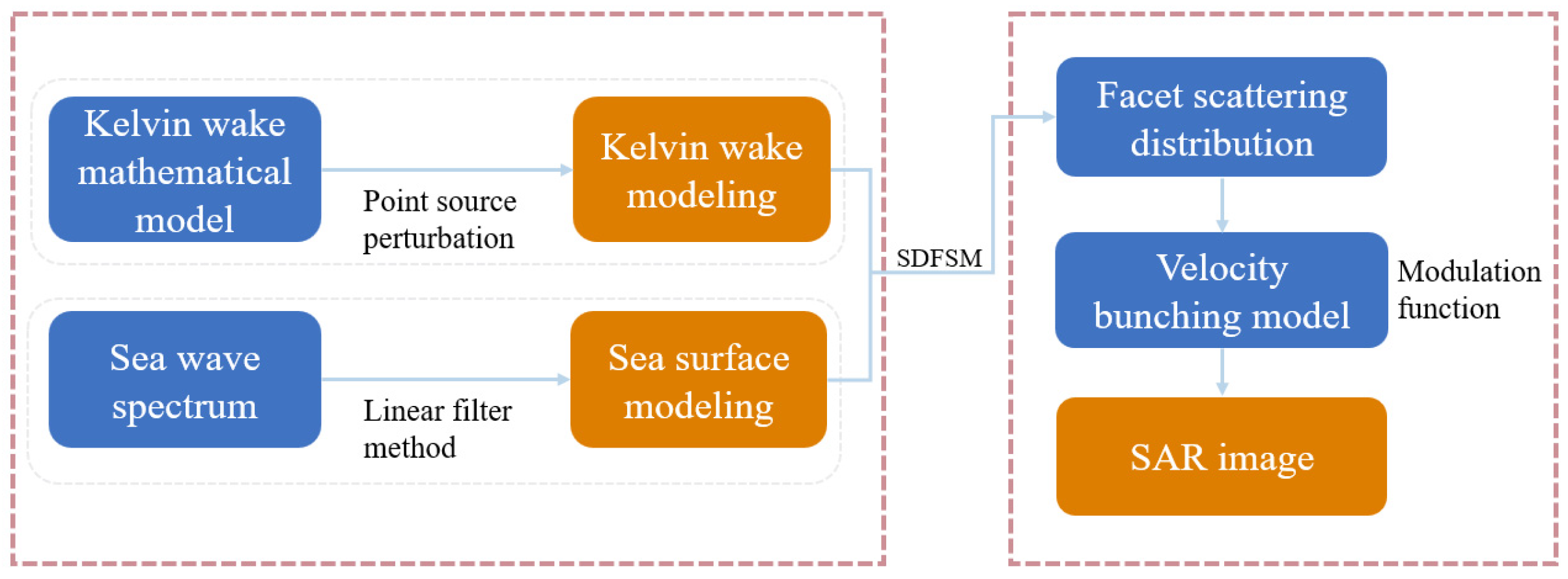
In Figure 1, a diagram of the relationship between the subsequent YOLOv5 method and electromagnetic scattering modeling is given.

2. Modeling Ship Wake and Sea Surface

The proper modeling of the sea waves and ship wake is of great necessity for the SAR imaging of ship wake in the marine environment. The randomness of waves can be described based on the geometric modeling of the wave spectrum model, and then the two-dimensional sea surface scene is simulated based on the linear filter method. The Kelvin wake mathematical model is used to simulate the wake, and then the electromagnetic scattering characteristics and SAR imaging are studied.

2.1. Elfouhaily Spectrum Model and Directional Function

In 1997, the Elfouhaily wave spectrum [23] was proposed via continuously optimizing the JONSWAP wave spectrum [24], the P-M wave spectrum [25], and other wave spectra. The Elfouhaily wave spectrum is a full wave spectrum. It consists of two parts, which are the longwave spectrum and the shortwave spectrum. The spectrum can be expressed as Equation (1):
ψE (k) = 1/k3[BL(k) + Bs(k)]
B L k is the longwave curvature spectrum, as shown in Equation (2):
B L = 1 2 α p L P M J P c k p c k exp Ω 10 k k p 1 / 2 1
In Equation (2), α p = 0.006 Ω , Ω is the inverse wave age, Ω = u 10 / c k p , u 10 is the wind speed at 10 m above sea level, c k is the phase velocity of the wave, and c k = g / k 1 + k 2 / k m 2 , k m = 363   r a d / m , k p = g Ω 2 / u 10 2 is the wavenumber corresponding to the peak of the spectrum, L P M = exp 1.25 k p / k 2 , and J p = γ Γ .
γ = 1.7 , 0.84 < Ω < 1 1.7 + 6 log Ω , 1 < Ω < 5
Γ = exp k k p 1 2 2 0.08 1 + 4 Ω 3 2
B s k is the shortwave curvature spectrum, as shown in Equation (5):
B S k = 0.5 α m c k m c k exp 1 4 1 k k m 2
α m = 0.01 1 + ln u f / c k m , u f c k m 1 + 3 ln u f / c k m , u f > c k m
In Equation (6), u f is the friction wind speed.
In order to accurately describe the anisotropic characteristics of ocean waves, the directional function is introduced on the basis of the ocean wave spectrum. The directional function reflects the changing directional characteristics of the ocean waves and the energy change relationship of waves with various frequency components caused by the wind direction above the sea surface. There are many common directional functions, such as Donelan directional function [26], Mitsuyasu directional function [27], Hwang directional function [28], etc. Here we use the Mitsuyasu directional function, which is expressed in Equation (7):
Φ M i t s ( k , φ ) = G ( s ) cos φ φ w 2 2 s
s = 1 1 ln 2 ln 1 Δ k 1 + Δ k
G s = 1 π π cos 2 s φ 2 d φ
where s denotes the concentration ratio of the directional function, Δ k is the upwind-crosswind radio, and its expression is shown in Equation (10) as follows:
Δ k = tanh ln 2 4 + 4 c k c k p 2.5 + 0.13 u f c k m c k m c k 2.5

2.2. Sea Surface Modeling

The sea surface modeling is accomplished based on the linear filtering method, which regards the sea surface as several different harmonics satisfying an independent Gaussian distribution. These harmonic components are processed by the Fast Fourier transform (FFT), and then the fluctuation of the sea surface can be obtained by the inverse Fast Fourier transform (IFFT), as shown in Equation (11):
h s e a ( r , t ) = k A ( k , t ) exp ( i k r )
where r = (x, y) is the spatial vector of the sea surface, k is the wavenumber of sea waves, t is the time parameter, and A(k, t) is the kernel function that contains information about sea waves with various frequencies.
A k , t = ϒ k S k δ k x δ k y / 2 e i ω t + ϒ k S k δ k x δ k y / 2 e i ω t
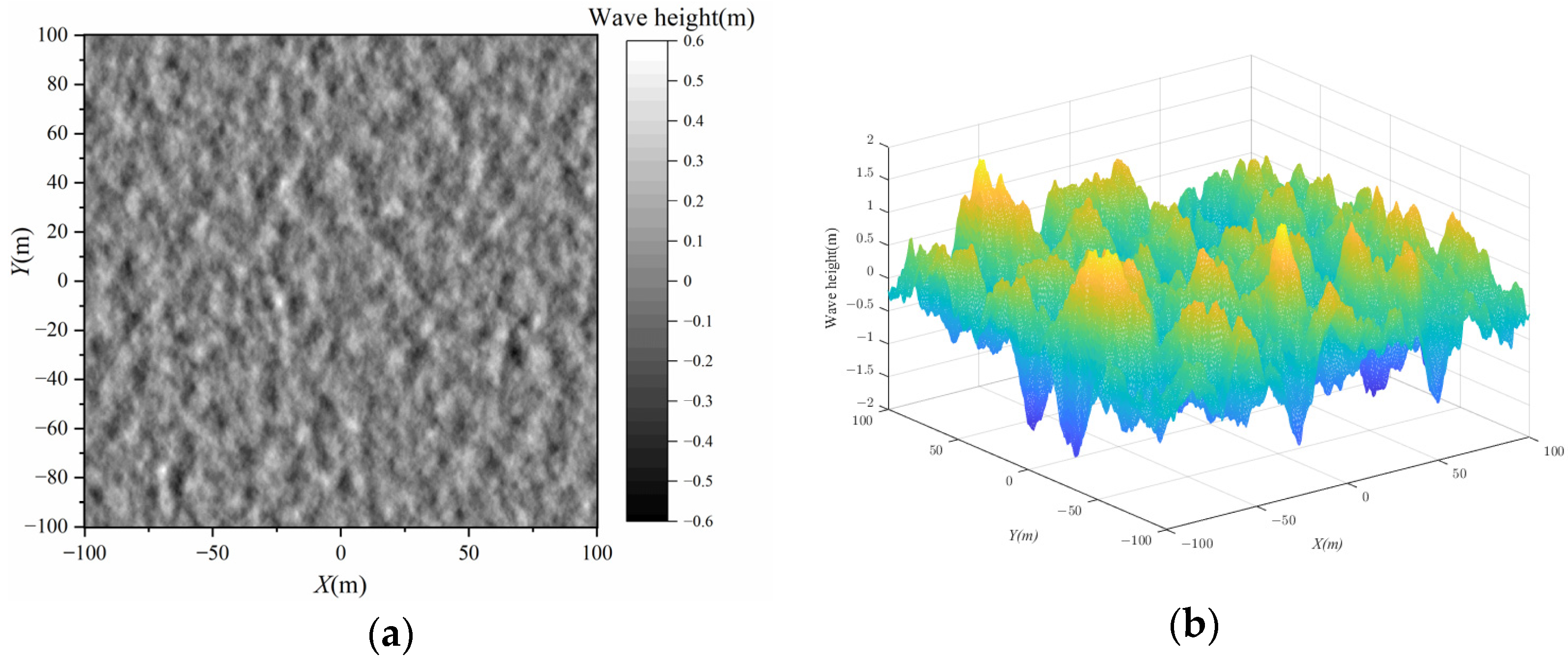
In Equation (12), S k is the two-dimensional wave spectrum, and k = k m , k n is the two-dimensional wavenumber vector, k m = m δ k x , k n = n δ k y , m, and n denote discrete intervals in the x and y directions, respectively. It should be noted that the transform must strictly satisfy the Nyquist sampling theorem. The simulation result is shown in Figure 2. The wind speed is assigned 5 m/s in Figure 2a, and the wind speed is defined as 10 m/s in Figure 2b. The range of the ocean scene is 200 m × 200 m.

2.3. Kelvin Wake Modeling

The wake is the trace left by the ship sailing on the water’s surface. The wake usually remains on the water’s surface for a period of time. Through the observation of the wake, certain hull information can be obtained. The Kelvin wake is a type of surface gravity wave produced in the process of ship motion, whose wave height can be calculated by Equation (13) [29]:
ζ ( x , y ) = 8 b π k r 2 l 2 π / 2 π / 2 1 e k r d sec 2 θ sin k r sec 2 θ ( x cos θ + y sin θ ) d θ
In Equation (13), k r = g / U s 2 , and U s is the speed of the ship. l is the half-length of the ship, b refers to the half-beam, d represents the draft, and θ indicates the wave direction with respect to the x direction.
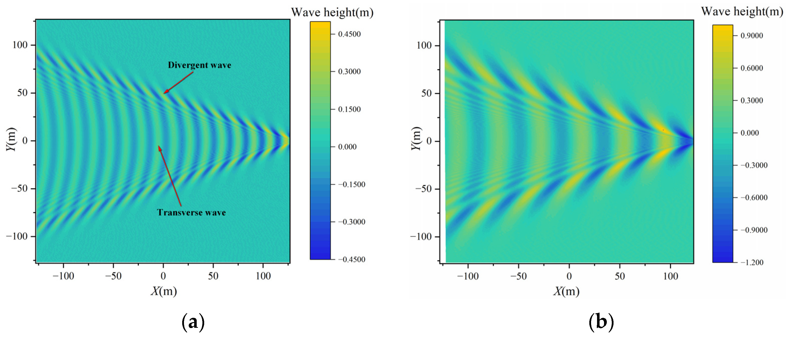
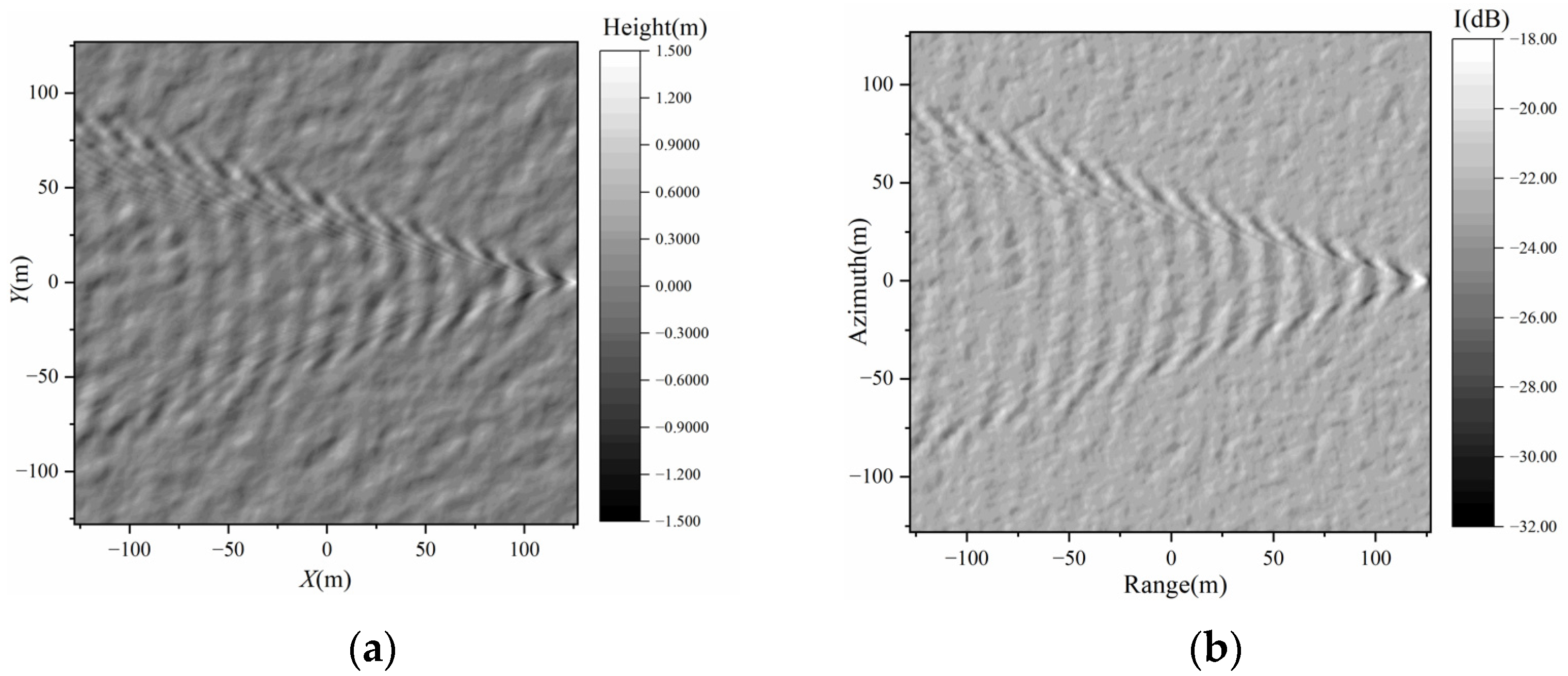
Figure 3 presents the wave height simulation results of the Kelvin wake. It is worth noting that when the ship speed increases, the divergent wave and the transverse wave both change, and the change trend is also consistent with the actual law of moving ships.
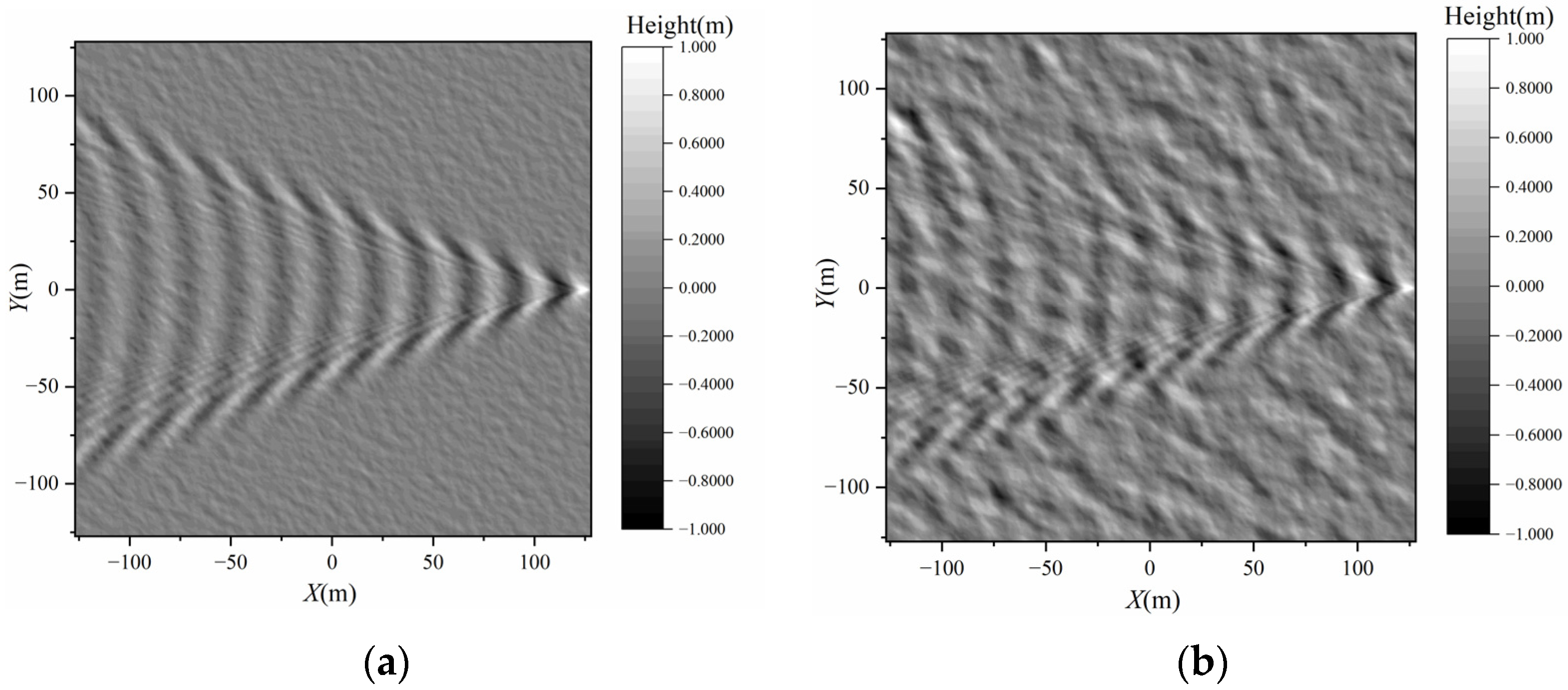
After superimposing the sea surface background and Kelvin wake, the simulated sea surface-Kelvin wake composite scene can be obtained, as shown in Figure 4.

3. Surface Scattering Distribution of Ship Wake on the Sea Surface

Understanding the electromagnetic wave interactions with the sea surface and target is essential to the SAR imaging simulation of a target in the marine environment. Research on electromagnetic scattering from the ocean surface and wake can deeply reveal SAR ocean surface imaging mechanisms.

3.1. Semi-Deterministic Facet Scattering Model

The semi-deterministic facet scattering model (SDFSM) is employed to deal with the electromagnetic scattering distribution of wake-surface scenes, which can efficiently and reasonably estimate the electromagnetic scattering characteristics of the target and sea surface on the large-scale ocean scene [30]. The scattering contribution of the facet can be composed of two parts. One is the scattering coefficient of an arbitrarily inclined slightly rough facet with a medium incident angle, as shown in Equation (14):
σ P Q T S P M k ^ i , k ^ s = π k 4 | ε 1 | 2 F ˜ P Q 2 S ζ q l
and the other is the scattering coefficient of a facet with a small incident angle, as denoted in Equation (15):
σ P Q K A M k ^ i , k ^ s = π k 2 | q | 2 q z 4 F P Q K A M 2 P z x tan , z y tan
Equation (16) is the total scattering contribution of facets:
σ P Q t o t a l k ^ i , k ^ s = 1 A M m = 1 N n = 1 σ P Q , m n K A M k ^ i , k ^ s + σ P Q , m n T S P M k ^ i , k ^ s Δ x Δ y
In Equations (14)–(16), k ^ i and k ^ s represent the incident and scattering direction unit vectors, respectively, q = k k ^ s k ^ i . k represents the incident wave number of an electromagnetic wave. The projection vector of q on the mean plane of z = 0 is denoted by q l . S ζ q l is the spatial power spectrum of a slightly rough surface. F indicates the polarization factor, whose subscripts P, Q = H, V represent the polarization modes of scattered and incident waves, respectively (H denotes horizontal polarization and V denotes vertical polarization). z x tan and z y tan are the slopes of the tangent plane of the mirror point, respectively. Δx and Δy are represented as sampling intervals. N and M refer to the number of sampling points in the y and x directions, respectively. A is the area of the two-dimensional scene.

3.2. Facet Scattering Distribution Based on SDFSM

The facet scattering distribution of the sea surface and its Kelvin wake are created on the basis of the SDFSM model, as illustrated in Figure 5. The radar incident frequency is 12 GHz, and the radar incident angle is 60°. The size of the ocean scene is 256 m × 256 m, and the discrete intervals in the x and y directions are both 1 m. The ship is 178 m long and 21 m wide, and its draft depth is 6.6 m. The wind speed is 3 m/s, and the ship speed is 5 m/s. According to the simulation results, it can be seen that the characteristics of the wake can be clearly observed in co-polarization conditions. Under the condition of VH polarization, not only the sea surface texture feature is almost lost, but also only the linear feature of the wake target can be observed. The simulation results show that the scattering amplitude is the largest under VV polarization. At the same time, the scattering amplitude is the smallest in the case of VH polarization. The difference between the maximum and minimum scattering amplitudes is the largest under HH polarization.

4. Simulation of SAR Image Sample of Ship Wake

For the purpose of accurately identifying ship targets, the wake characteristics left by ships have provided important information for identifying ships. Wakes are easier to identify than ships. In addition, the speed, position, direction, and other information of the ship can also be obtained through a specific algorithm by analyzing the wake information. Since it is difficult to obtain the measured data of a wake SAR image, it is necessary to study it by SAR image simulation [31]. Based on the simulation presented in this section, adequate SAR image samples would be obtained to establish an appropriate data set for YOLOv5.

SAR Image Simulation of Ship Wake in Sea Background

After obtaining the facet scattering distribution of ship wake under the ocean background and then combining the SAR imaging mechanism of sea waves, the simulation of the SAR image of ship wake can be performed, as shown in Figure 6.
Figure 6 shows the implementation process of SAR imaging in the composite scene of sea surface and ship wake:
  • Simulation of a two-dimensional sea scene by the linear filter method;
  • Simulation of wake by the Kelvin wake mathematical model;
  • Superposition of the sea surface and Kelvin wake;
  • Scattering distribution of sea wake based on a semi-deterministic facet model;
  • Simulation of the Kelvin wake SAR image based on the modulation model.
According to the aforementioned procedure, the simulated SAR image of the sea surface and its composite wake scene are presented in Figure 7. The radar incident wave frequency is set to 12 GHz, the radar incident angle is 60°, R/V = 60 s, and the integral time of the scene is 0.2 s. The size of the scene is 256 m × 256 m, and the discrete intervals in x and y directions are both 1 m. The sea surface wind speed is set at 5 m/s, while the angle of the wind direction is set at 135°. The speed of the ship is 5.0 m/s, and the course is 0°. ‘I’ in Figure 7 represents the image intensity.
According to the simulation results, what can be observed is that the wake texture features, both the divergent wave and transverse wave, can be accurately described in SAR images in HH polarization or VV polarization. However, in this configuration, the transverse wave could not be observed in a VH polarization condition.

5. Ship Wake Detection Method

Traditional detection methods cannot efficiently and accurately identify wake targets under nonlinear sea surface and high sea state conditions. Therefore, here we apply the detection method of YOLOv5 to detecting the nonlinear wake and weak wake targets with satisfactory efficiency and accuracy. For comparison, one of the representative methods—the Radon transform is also provided here.

5.1. Traditional Wake Detection Method

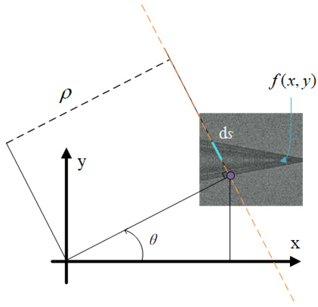
Radon transform was formally applied to image processing in the 1920s. With the continuous development of SAR until the 1990s, the Radon transform was applied to the detection of ship wakes. The main principle of this method is to project the original image along a straight line. When these pixels in the same direction are mapped to the transform domain, they will be reflected in the form of a point. According to this feature, we can judge whether there is a straight line in the original image. The Radon transform is depicted in Figure 8, and its mapping relationship is noted in Equation (17).
ρ = x cos θ + y sin θ ρ , θ
The Radon transform can be expressed as Equation (18) [32].
R ( ρ , θ ) = D f ( x , y ) δ ( ρ x cos θ y sin θ ) d x d y
where D represents the original image. f(x,y) denotes the gray value of any point (x,y) in the image. δ is the impulse function. ρ represents the shortest distance from the origin to the line and θ is the angle from the direction of the shortest path to the x axis.
The Radon transform is insensitive to dark wakes. For such defects, local Radon transformation can be improved. Local Radon transform is still carried out in the whole image, but here the whole image should be divided into small segments by using a small window, and then the integration along a short line could be finally performed. It can be expressed as Equation (19):
f ( θ , ρ , σ ) = x m i m x max y min y max f ( x , y ) δ ( ρ x cos θ y sin θ ) d y d x
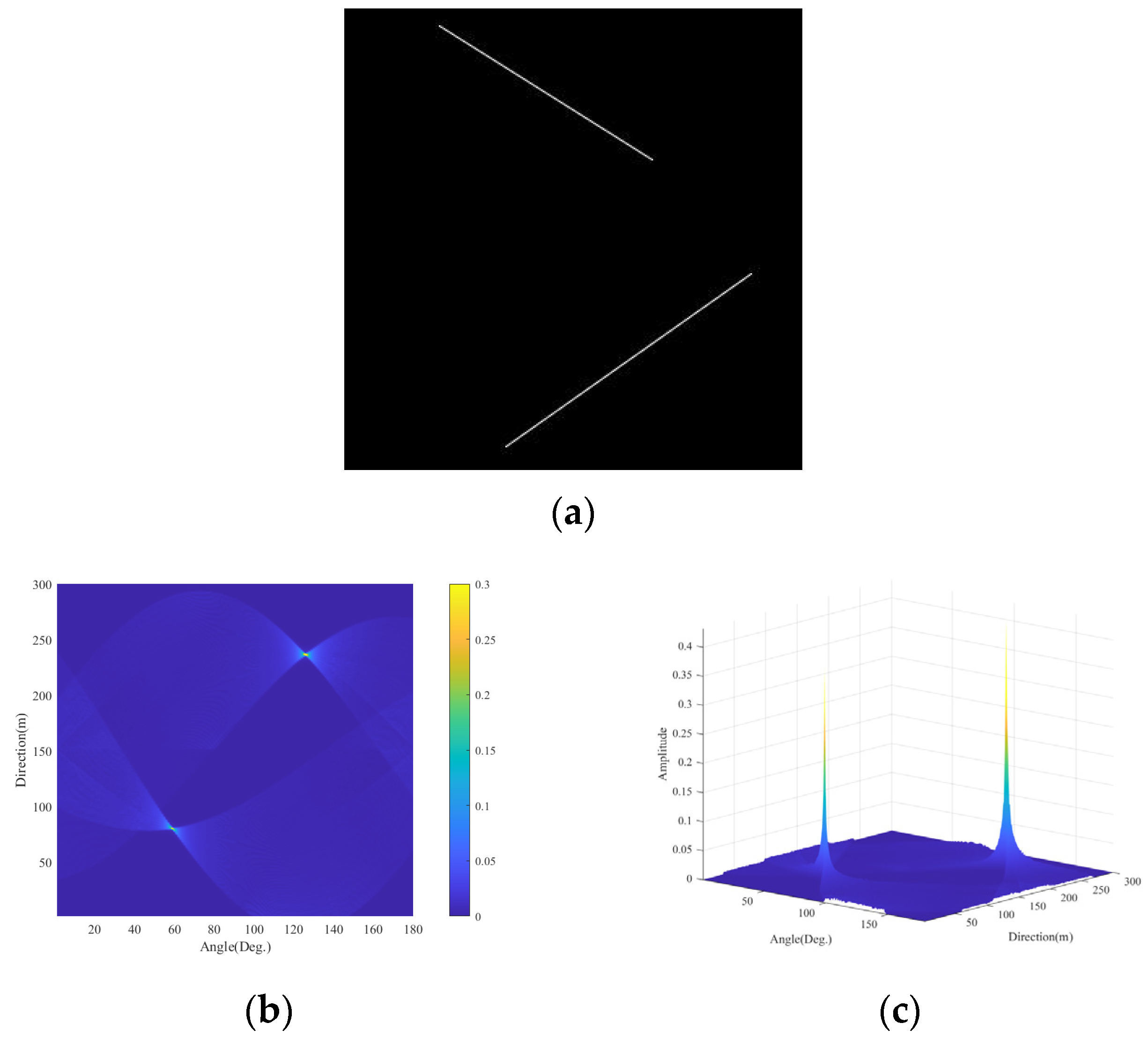
Firstly, an image that only contains two straight lines is chosen to illustrate the Radon transform in Figure 9. From Figure 9b,c, it can be clearly seen that two straight lines in the original image will be shown as two peaks in the transform domain of the Radon transform. Based on the peak point, the unique pair of ( ρ ,   θ ) could be determined, and then the two straight lines could be marked in the original image. This phenomenon well reflects the mechanism of Radon transform.
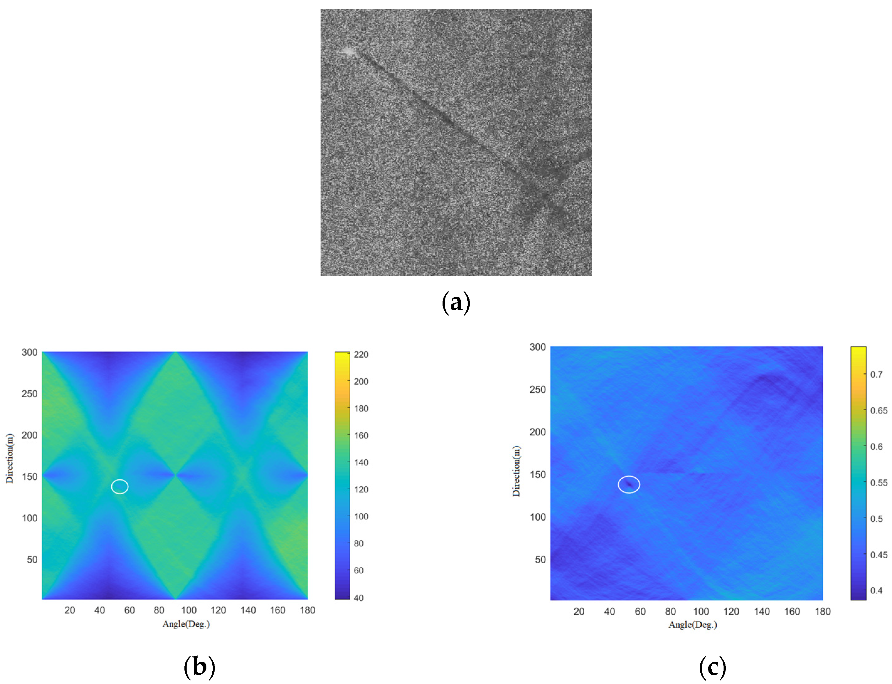
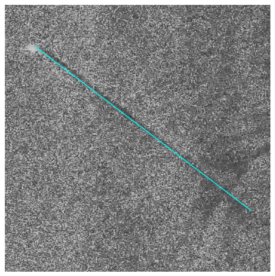
The measured wake ERS-2 SAR image is also selected for the Radon transform test [33]. As shown in Figure 10a, the wake in the measured SAR image is darker than the background.
Figure 10b,c demonstrates the difference between the results in the transform domain after the Radon transform and the local Radon transform processing of Figure 10a, respectively. After denoising the measured SAR image, we can see that, in the Radon transform domain, the dark wake in the original SAR image is mapped to a dark point (noted by the white circle in Figure 10b) that is submerged in noise and can be barely seen, but in the local Radon transform, the linear dark wake in the original SAR image appears as an obvious dark point (noted by the white circle in Figure 10c). Figure 11 shows the final wake detection results.
However, even the improved Radon transform could not cope with nonlinear wakes either. Based on the Radon transform theory, the final identification can only be accomplished by cutting the nonlinear wakes into a large number of tiny linear segments. The test is performed as follows:
  • Apply windows to split nonlinear wakes;
  • Detect line segments that can be approximated by a straight line in each small image;
  • Combine small line segments.
Although it is a popular method of detection, there are still many problems. First, the size of the window may vary with the type and shape of the wake, which causes weak generalization ability. Second, the detection efficiency is too poor, so the Radon transform has great limitations in detecting nonlinear wakes. In addition, even when the linear wake is almost submerged in the noise background, the detection effect will still be greatly reduced. To solve the above issues, an efficient deep-learning based scheme would be a favorable choice.

5.2. Wake Detection Method Based on YOLOv5

The YOLOv5 deep learning framework has been chosen to improve the wake detection in this paper, which has the advantages of great generalization ability and flexibility in application scenarios. YOLOv5 has such versatile network structures that even a portable computer could afford the computation burden of YOLOv5. The wake detection with the help of YOLOv5 in this paper is presented in the following sections.

5.2.1. YOLOv5 Environment Configuration

The hardware configuration is given in Table 1:
Software configuration:
  • CUDA
CUDA is a parallel computing framework from NVIDIA that aims to use the fewest device resources possible to achieve more efficient parallel computing. The framework supports C, C++, Fortran, Python, Java, and other languages. The CUDA 10.2 version is selected for the environment configuration here.
2.
CUDNN
The full name of CuDNN is NVIDIA CuDNN, which is a GPU-accelerated deep neural network primitive library. It has the advantages of high performance, low memory usage, and simplicity. This software has strong compatibility and can be integrated into many machine learning frameworks. The platform can effectively help developers study and improve neural networks. The cudnn 10.2 version was used in the environment configuration of this study.
3.
Pytorch
Pytorch is an open-source Python machine learning library owned by Facebook. The software is widely used in machine learning and provides a high-quality experimental platform for deep learning. In this study, Pytorch 1.5.1 was selected in the environmental configuration.

5.2.2. Preparation of YOLOv5 Training Samples

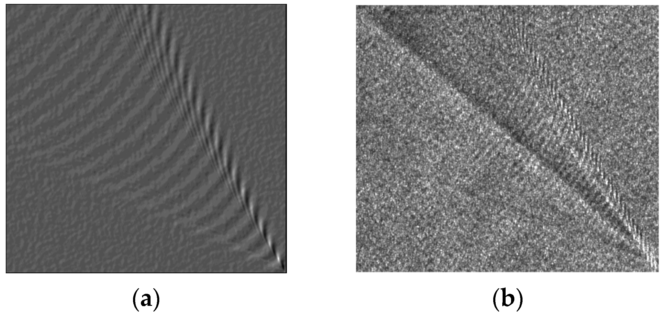
The sea surface has waves of different scales that are complex and random, which makes it difficult to identify wakes. Training sets for training are from SEASAT SAR and TerraSAR-X [34,35]. In order to highlight the wake features in the training set and expand the training set samples, the simulation samples are used as part of the training set, and then the measured images are further filtered, enhanced, and reversed. Finally, a total of about 500 ship wake samples are obtained, of which 10% are chosen as the test set. Figure 12 displays the comparison between simulated SAR images of ship wake based on the scattering model and TerrSAR-X measured images. It can be seen that the SAR image based on electromagnetic scattering simulation can accurately predict the characteristics of diffusion and transverse waves in a Kelvin wake measured image. Therefore, it is feasible to expand the data set by using the simulated images to complete the wake detection based on YOLOv5.
After obtaining a certain amount of data, the target should be marked in the training set. In this paper, the target of the training set is labeled ‘wake’ in the following results. Table 2 shows the hyperparameters used for training.

5.2.3. YOLOv5 Training Results and Test Results Analysis

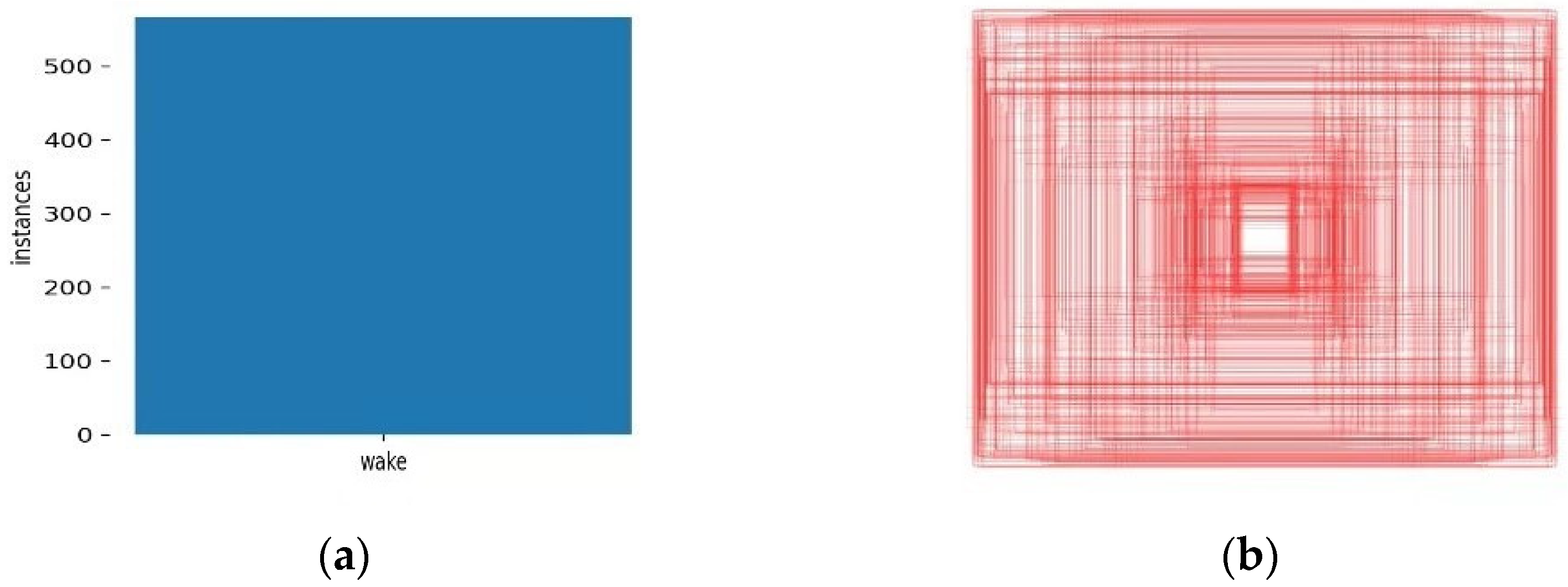
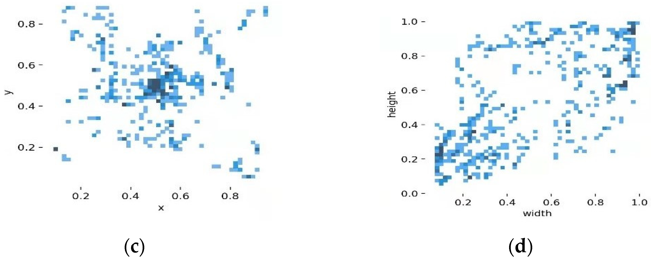
Figure 13 illustrates the training model, which shows the statistics of the number of ship target data sets, annotation boxes, target location, and target size information. Figure 13a illustrates that the data set contains more than 500 wake targets; Figure 13b depicts the annotation boxes; Figure 13c shows where the targets are distributed in the image; and Figure 13d displays the size of the wake targets, from which we can see that the targets of small and large size are the majority, while the targets of medium size are few in number in the training set.
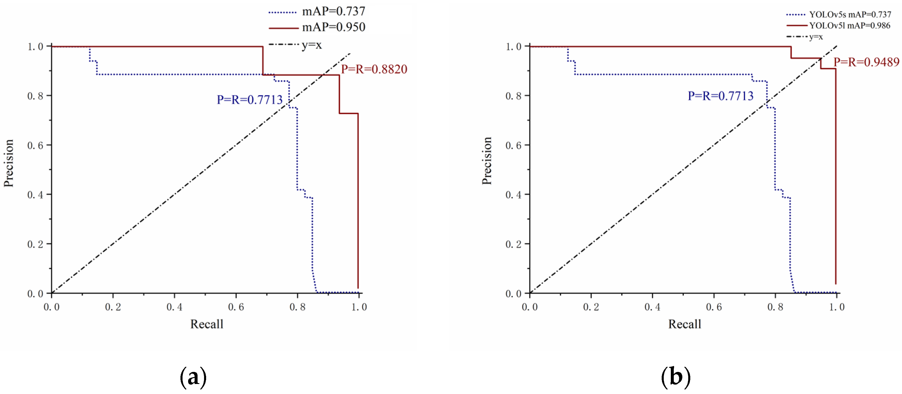
In the YOLOv5s network structure, the ratio of training set to test set in the total data is 9:1. The test set selects simulated wake targets under different sea conditions. As shown in Figure 14a, the relevant figure of ‘Precision-Recall’ (P-R) is given. It can be seen from the figure that the average detection accuracy can reach 95.0% in low sea states, but the detection accuracy is decreased to 73.7% in high sea states, as shown in Table 3. It can be seen that in this case, YOLOv5s has a very good detection effect in the low sea state. Now we focus on the study of wake targets in high sea states using different network structures.
Among the YOLOv5’s detection network, the YOLOv5s and YOLOv5l are chosen to be compared in Table 4. The former has the smallest depth and width, while the latter has larger ones. YOLOv5s has a network depth of 0.33 and a network width of 0.50. YOLOv5l has a network depth of 1.0 and a network width of 1.0. As shown in Figure 14b, with the increased depth and width, the detection accuracy has improved. On the contrary, in actual detection, the detection speed of YOLOv5s is only tens of milliseconds. The detection time of YOLOv5l is several times that of YOLOv5s, and under the same epoch and batch conditions, the training time is also increased by more than three times.
With the aim of testing the detection performance of the wake in the measured SAR images under different network structures, the available measured wake SAR images are taken as the test set, and YOLOv5s and YOLOv5l are still selected as the algorithm network structure.
From the comparison in Table 5, it can be seen that when the measured SAR images are chosen as the test set, the detection accuracy of YOLOv5l is significantly higher than that of YOLOv5s. According to the ‘P-R‘ curve (dash dot line in Figure 15), YOLOv5l performs better from both the perspective of the area under the curve and the perspective of the intersection point where the p value and the R value are equal, which can effectively verify the advantages of YOLOv5l for detecting wake targets.
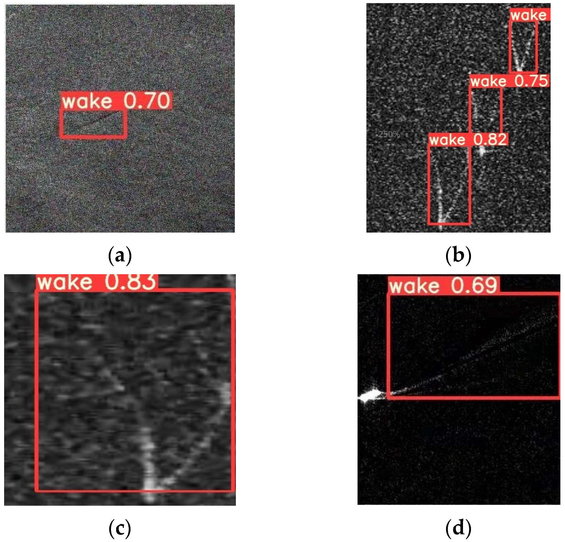
Figure 16 shows the detection effect of YOLOv5 on a single target, multiple targets, nonlinear wake, and weak wake. It can be seen that the prediction box of YOLOv5 can accurately identify the wake region, and the confidence level of the wake will be given in the prediction box. The accuracy and generalization ability of the training model will continue to be improved with the increase in the number and type of samples.

5.2.4. Comparison between the Yolov5 and Radon Transform Methods

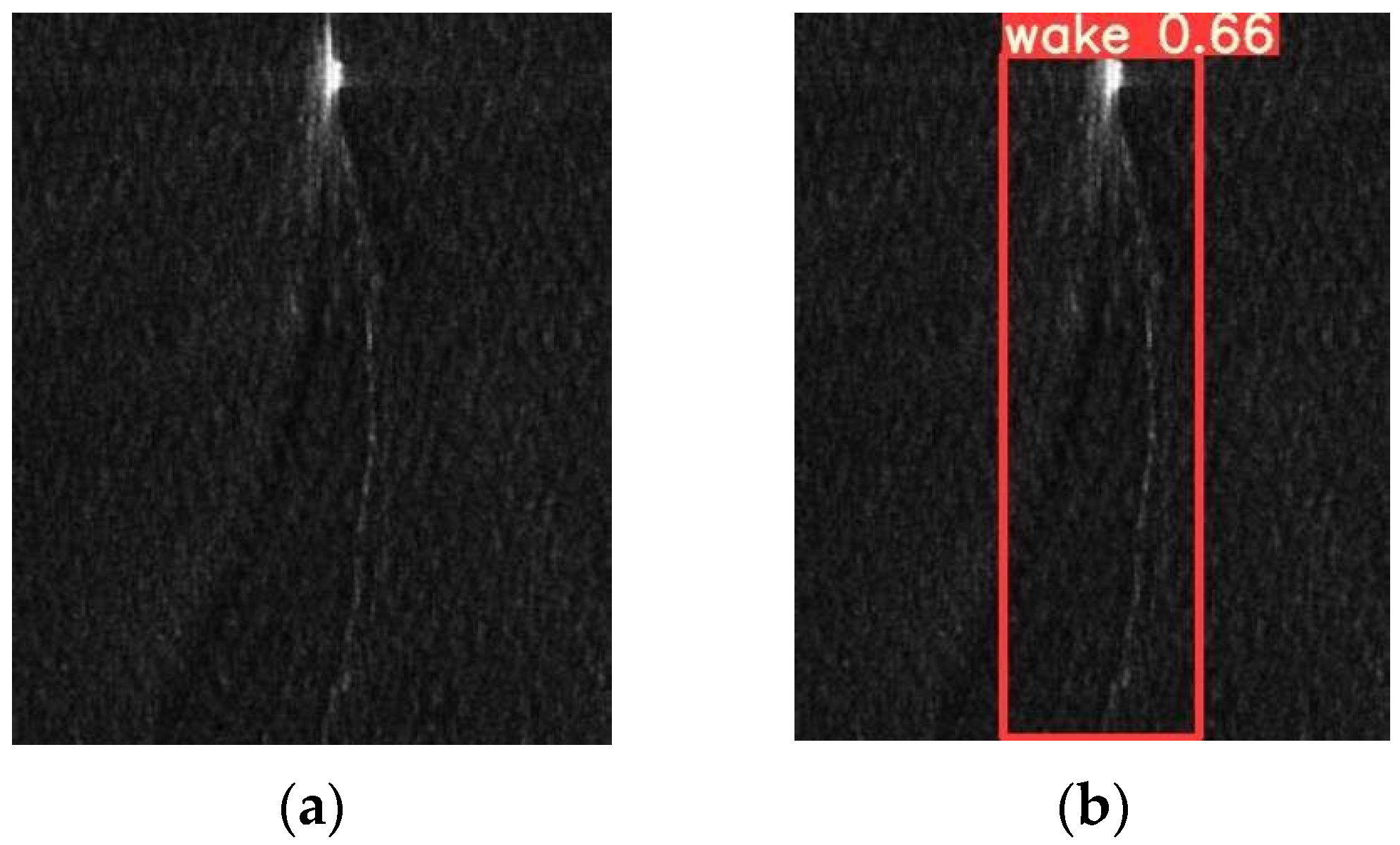
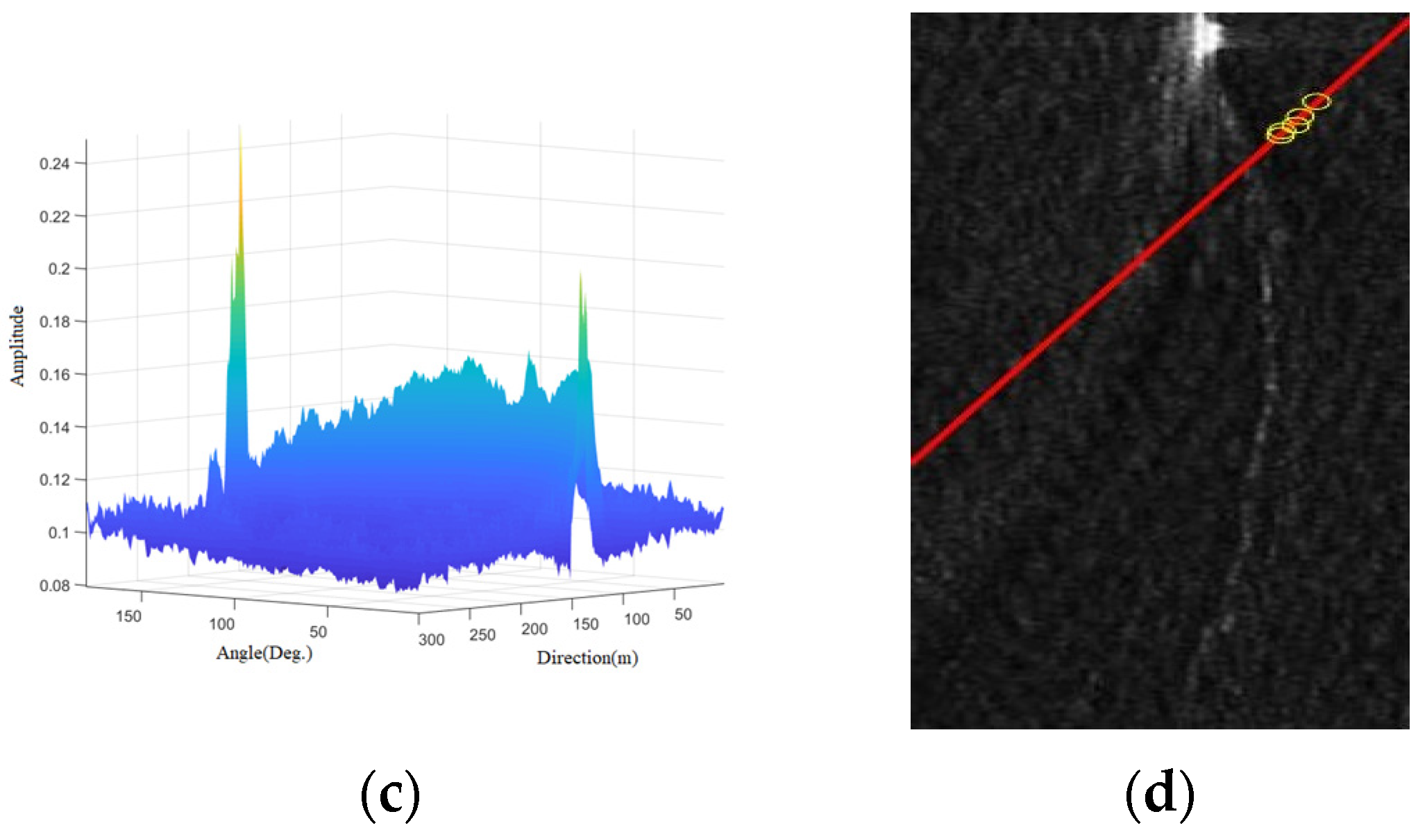
Here a nonlinear wake target (see Figure 17a) is selected for detection using the local Radon transform and YOLOv5, respectively. What can be noticed from Figure 17c is that after the local Radon transform has been applied to the wake data, the transform domain contains a large number of extreme points, while for comparison, in Figure 9c there is only one peak point in the transform domain corresponding to a straight line. Even though the peak point can only determine a straight line according to the transform principle, the information of the curvilinear wake cannot be described. To make a comparatively fair comparison, we try to choose several relatively obvious peak points in the Radon transform domain to inverse the straight line, the inversion result is shown as a red line in Figure 17d, which reflects that the nonlinear wake cannot be accurately detected by the traditional Radon transform. In contrast, the prediction frame in the YOLOv5 algorithm can accurately identify the wake information see Figure 17b.
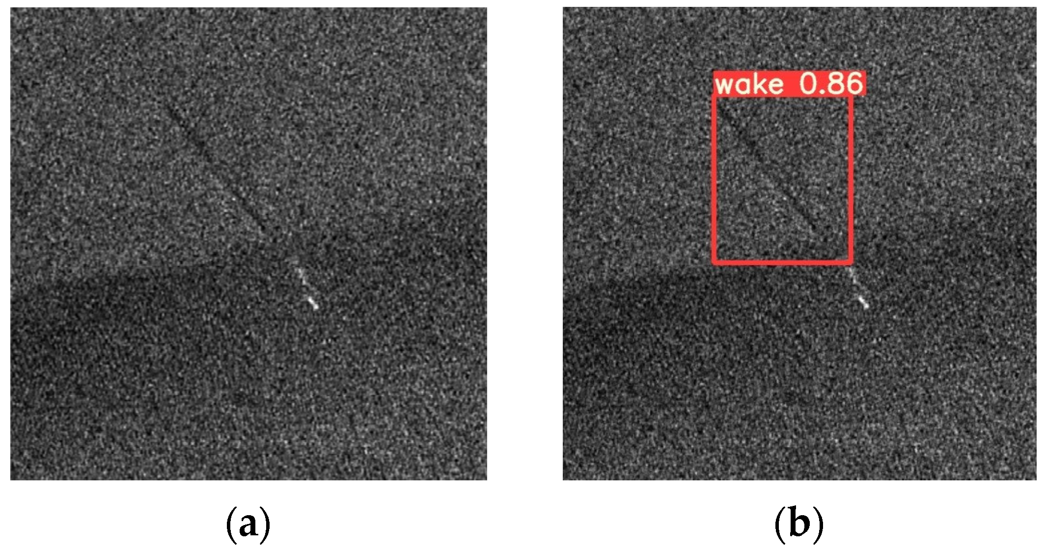
Here, the wake target under a strong noise background is selected and detected by the local Radon transform and YOLOv5, respectively. As can be observed from Figure 18c, after local Radon transform, the peak points in the transform domain are not obvious, and the process of peak screening and extraction requires a lot of resources, which means that wake detection in a strong noise environment is still difficult. Similarly, the inversion result in Figure 18d also indicates that the Radon transform is inadequate to detect the weak wake in a strong noise environment. Figure 18b illustrates the detection result of YOLOv5. It has no difficulty knowing that the prediction box can accurately identify weak wake information. Different wake types are detected using the YOLOv5 and Radon transforms, respectively. The comparison is demonstrated in Table 6:

6. Conclusions

In this paper, the detection of ship wakes in SAR images on the basis of electromagnetic scattering method and deep learning technique is studied. After establishing a composite model of the sea surface and its wake, a semi-deterministic facet scattering model and modulation imaging model are used to simulate the composite SAR image of the sea surface and its wake. These simulations comprise ship wake SAR images under different sea conditions, various ship types, and diverse ship speeds as well as headings, which provide a large number of samples for wake target detection research based on deep learning methods. Then the nonlinear wake and weak wake are detected based on the YOLOv5 algorithm. According to the results analysis, it indicates that the YOLOv5 detection algorithm solves the defect that the nonlinear characteristics cannot be directly detected in the traditional wake detection method, effectively detects nonlinear wake and weak wake and improves detection efficiency. In accordance with the problem of ship wake detection in a complex environment, the detection effect may still be improved in future work, and the SAR images of narrow V wake and internal wave wake in surge environments will be studied in the future, which will provide more abundant training samples for deep learning in wake detection research.

Author Contributions

Conceptualization, D.N.; data curation, H.W.; formal analysis, H.W.; funding acquisition, D.N. and M.Z.; methodology, H.W. and D.N.; project administration, M.Z.; resources, D.N. and M.Z.; supervision, D.N.; validation, H.W.; visualization, L.T.; writing—original draft, H.W.; writing—review and editing, D.N. and Y.Z. All authors have read and agreed to the published version of the manuscript.

Funding

This research was funded by the 111 Project, grant number B17035; the Fundamental Research Funds for the Central Universities, grant number QTZX22032; and the National Natural Science Foundation of China, grant number 62171351.

Acknowledgments

The authors would like to thank the editors and anonymous reviewers for providing invaluable and constructive comments and suggestions.

Conflicts of Interest

The authors declare no conflict of interest.

References

  1. Chen, K.S. Principles of Synthetic Aperture Radar Imaging: A System Simulation Approach; CRC Press: Boca Raton, FL, USA, 2016; pp. 173–197. [Google Scholar]
  2. Jackson, C.R.; Apel, J.R. Synthetic Aperture Radar Marine User’s Manual; US Department of Commerce: Washington, DC, USA, 2004.
  3. Li, X.M.; Lehner, S.; Bruns, T. SAR measurement of ocean sea surface wind and wave for operational ship routing. In Proceedings of the 2011 IEEE International Geoscience and Remote Sensing Symposium, Vancouver, BC, Canada, 24–29 July 2011; pp. 1334–1337. [Google Scholar] [CrossRef]
  4. Guo, C.; Ai, W.; Hu, S.; Du, X.; Chen, N. Sea surface wind direction retrieval based on convolution neural network and wavelet analysis. IEEE J. Sel. Top. Appl. Earth Obs. Remote Sens. 2022, 15, 3868–3876. [Google Scholar] [CrossRef]
  5. Bayındır, C.; Frost, J.D.; Barnes, C.F. Assessment and enhancement of SAR noncoherent change detection of sea-surface oil spills. IEEE J. Ocean. Eng. 2018, 43, 211–220. [Google Scholar] [CrossRef]
  6. Wang, J.; Zheng, T.; Lei, P.; Bai, X. Ground target classification in noisy SAR images using convolutional neural networks. IEEE J. Sel. Top. Appl. Earth Obs. Remote Sens. 2018, 11, 4180–4192. [Google Scholar] [CrossRef]
  7. Luo, S.; Yu, J.; Xi, Y.; Liao, X. Aircraft target detection in remote sensing images based on improved YOLOv5. IEEE Access 2022, 10, 5184–5192. [Google Scholar] [CrossRef]
  8. Wang, J.; Zhang, M.; Cai, Z.; Chen, J. SAR imaging simulation of ship-generated internal wave wake in stratified ocean. J. Electromagn. Waves Appl. 2017, 31, 1101–1114. [Google Scholar] [CrossRef]
  9. Zhang, C.; Gao, G.; Zhang, L.; Chen, C.; Gao, S.; Yao, L.; Bai, Q.; Gao, S. A Novel full-polarization SAR images ship detector based on the scattering mechanisms and the wave polarization anisotropy. ISPRS J. Photogramm. Remote Sens. 2022, 190, 129–143. [Google Scholar] [CrossRef]
  10. Nie, D.; Zhang, M.; Wei, P.; Man, M. Electromagnetic bistatic scattering features of shallow water waves over upslope submarine topography. IEEE J. Sel. Top. Appl. Earth Obs. Remote Sens. 2021, 14, 9873–9883. [Google Scholar] [CrossRef]
  11. Zhang, M.; Li, J. Numerical simulation and analyses of SAR images from ship wakes. In Proceedings of the 2019 International Applied Computational Electromagnetics Society Symposium (ACES), Miami, FL, USA, 14–19 April 2019; pp. 1–2. [Google Scholar]
  12. Biondi, F. A polarimetric extension of low-rank plus sparse decomposition and Radon transform for ship wake detection in synthetic aperture radar images. IEEE Geosci. Remote Sens. Lett. 2019, 16, 75–79. [Google Scholar] [CrossRef]
  13. Xu, J.; Sun, X.; Zhang, D.; Fu, K. Automatic detection of inshore ships in high-resolution remote sensing images using robust invariant generalized Hough transform. IEEE Geosci. Remote Sens. Lett. 2014, 11, 2070–2074. [Google Scholar] [CrossRef]
  14. Wang, S.; Jin, Y. Ship wake detection in SAR images based on Radon transformation and Morphologic image processing. J. Remote Sens. 2001, 4, 289–294. [Google Scholar] [CrossRef]
  15. Karakuş, O.; Rizaev, I.; Achim, A. Ship wake detection in SAR images via sparse regularization. IEEE Trans. Geosci. Remote Sens. 2020, 58, 1665–1677. [Google Scholar] [CrossRef] [Green Version]
  16. Zhang, T.; Zhang, X. High-speed ship detection in SAR images based on a grid convolutional neural network. Remote Sens. 2019, 11, 1206. [Google Scholar] [CrossRef] [Green Version]
  17. Kang, M.; Ji, K.; Leng, X.; Lin, Z. Contextual region-based convolutional neural network with multilayer fusion for SAR ship detection. Remote Sens. 2017, 9, 860. [Google Scholar] [CrossRef] [Green Version]
  18. Kang, K.M.; Kim, D.J. Ship velocity estimation from ship wakes detected using convolutional neural networks. IEEE J. Sel. Top. Appl. Earth Obs. Remote Sens. 2019, 12, 4379–4388. [Google Scholar] [CrossRef]
  19. Graziano, M.D.; Renga, A. Towards automatic recognition of wakes generated by dark vessels in Sentinel-1 images. Remote Sens. 2021, 13, 1955. [Google Scholar] [CrossRef]
  20. Ma, H.; Liu, Y.; Ren, Y.; Yu, J. Detection of collapsed buildings in post-earthquake remote sensing images based on the improved YOLOv3. Remote Sens. 2020, 12, 44. [Google Scholar] [CrossRef] [Green Version]
  21. Liu, S.; Kong, W.; Chen, X.; Xu, M.; Yasir, M.; Zhao, L.; Li, J. Multi-scale ship detection algorithm based on a lightweight neural network for spaceborne SAR images. Remote Sens. 2022, 14, 1149. [Google Scholar] [CrossRef]
  22. PyTorch-YOLOv5. Available online: https://github.com/ultralytics/yolov5 (accessed on 6 September 2021).
  23. Elfouhaily, T.; Chapron, B.; Katsaros, K. A unified directional spectrum for long and short wind-driven waves. J. Geophys. Res. 1997, 102, 15781–15796. [Google Scholar] [CrossRef] [Green Version]
  24. Hasselmann, K.; Barnett, T.P.; Bouws, E.; Carlson, H.; Gartwright, D.E.; Enke, K.; Ewing, J.A.; Gienapp, H.; Hasselmann, D.E.; Kruseman, P.; et al. Meansurements of wind-wave growth and swell decay during the Joint North Sea Wave Project (JONSWAP). Dtsch. Hydrogr. Z. Suppl. 1973, 12, 1–95. [Google Scholar]
  25. Pierson, W.J.; Moskowitz, L. A proposed spectral form for fully developed wind seas based on the similarity theory of S. A. Kitaigorodskii. J. Geophys. Res. 1964, 69, 5181–5190. [Google Scholar] [CrossRef]
  26. Donelan, M.A.; Hamilton, J.; Hui, W.H.; Stewart, R.W. Directional spectra of wind-generated ocean waves. Philos. Trans. R. Soc. Lond. Ser. A Math. Phys. Sci. 1985, 315, 509–562. [Google Scholar] [CrossRef]
  27. Mitsuyasu, H.; Tasai, F.; Suhara, T.; Mizuno, S.; Ohkusu, M.; Honda, T.; Rikiishi, K. Observations of the directional spectrum of ocean wavesusing a cloverleaf buoy. J. Phys. Oceanogr. 1975, 5, 750–760. [Google Scholar] [CrossRef]
  28. Hwang, P.A.; Wang, D.W. Directional distributions and mean square slopes in the equilibrium and saturation ranges of the wave spectrum. J. Phys. Oceanogr. 2001, 31, 1346–1360. [Google Scholar] [CrossRef]
  29. Oumansour, K.; Wang, Y.; Saillard, J. Multifrequency SAR observation of a ship wake. IEE Proc.-Radar Sonar Navig. 1996, 143, 275–280. [Google Scholar] [CrossRef]
  30. Chen, H.; Zhang, M.; Zhao, Y.; Luo, W. An efficient slope-deterministic facet model for SAR imagery simulation of marine scene. IEEE Trans. Antennas Propag. 2010, 58, 3751–3756. [Google Scholar] [CrossRef]
  31. Zhao, Y.; Zhang, M.; Zhao, Y.; Geng, X. A bistatic SAR image intensity model for the composite ship-ocean scene. IEEE Trans. Geosci. Remote Sens. 2015, 53, 4250–4258. [Google Scholar] [CrossRef]
  32. Bracewell, R.N. The Fourier Transform and Its Applications, 3rd ed.; McGraw-Hill: New York, NY, USA, 1986; pp. 356–357. [Google Scholar]
  33. Aerospace Information Research Institute. Available online: http://ids.ceode.ac.cn/ (accessed on 15 October 2021).
  34. Case, K.; Dashen, R.; Munk, W.; Vesecky, J.; Watson, K. SEASAT Report, Jason Rep. JSR 84-203; Mitre Corp.: McLean, VA, USA, 1985. [Google Scholar]
  35. HH Stripmap Mode TerraSAR-X Image of the Straight of Gibraltar. Available online: https://www.dlr.de/content/en/images/2011/1/spain-strait-of-gibraltar_333.html (accessed on 16 October 2021).
Figure 1. Diagram of the relationship between the YOLOv5 method and electromagnetic scattering modeling.
Remotesensing 14 05788 g001
Figure 2. Sea surface simulation results based on Elfouhaily wave spectrum and Mitsuyasu directional function. (a) gray-scale image; (b) three-dimensional image.
Remotesensing 14 05788 g002
Figure 3. Simulation results of Kelvin wake height. (a) The ship speed is 5 m/s; (b) The ship speed is 8 m/s.
Remotesensing 14 05788 g003
Figure 4. The simulated sea surface-Kelvin wake composite scene. (a) The ship speed is 6 m/s, and the wind speed is 3 m/s; (b) The ship speed is 6 m/s, and the wind speed is 5 m/s.
Remotesensing 14 05788 g004
Figure 5. Ship wake surface scattering distribution in sea background. (a) wake model; (b) VV polarization; (c) HH polarization; (d) VH polarization.
Remotesensing 14 05788 g005
Figure 6. Simulation flow chart of ship wake SAR image in sea background.
Remotesensing 14 05788 g006
Figure 7. Simulated SAR image of ship wake in different polarization conditions. (a) wake model; (b) VV polarization; (c) HH polarization; (d) VH polarization.
Remotesensing 14 05788 g007aRemotesensing 14 05788 g007b
Figure 8. Schematic representation of the Radon transform.
Remotesensing 14 05788 g008
Figure 9. Example of the Radon transform. (a) an image contains two straight lines; (b) an aerial view of the result in the Radon transform domain; (c) a three-dimensional view of the result in the Radon transform domain.
Remotesensing 14 05788 g009
Figure 10. Wake detection results based on the Radon transform. (a) measured SAR wake image; (b) result after Radon transform processing; (c) result after local Radon transform processing.
Remotesensing 14 05788 g010
Figure 11. Wake detection results by local Radon transform.
Remotesensing 14 05788 g011
Figure 12. Comparison of (a) a simulated SAR image of a ship’s wake based on a semi-deterministic facet model and (b) a TerraSAR-X measured image.
Remotesensing 14 05788 g012
Figure 13. Statistical diagram of the ship wake training model. (a) sample number of the data sets; (b) annotation boxes; (c) locations of the targets; (d) spatial size of the targets.
Remotesensing 14 05788 g013aRemotesensing 14 05788 g013b
Figure 14. P-R Curve of a simulated SAR Image as test set: (a) P-R curves in different sea states (Low sea state: red line; High sea state: blue dot line); (b) P-R curves under different network structures.
Remotesensing 14 05788 g014
Figure 15. P-R Curve of the measured SAR Image as a test set.
Remotesensing 14 05788 g015
Figure 16. Results of ship wake recognition: (a) single target; (b) multiple targets; (c) nonlinear wake; (d) weak wake.
Remotesensing 14 05788 g016
Figure 17. The comparison diagram of the nonlinear wake detection result: (a) curvilinear wake; (b) result of YOLOv5 detection; (c) result in the Radon transform domain; and (d) inversion result of the local Radon transform based on several most obvious peaks in (c).
Remotesensing 14 05788 g017aRemotesensing 14 05788 g017b
Figure 18. The comparison diagram of the result of weak wake detection: (a) wakes in a strong noise background; (b) result of YOLOv5 detection; (c) result in the Radon transform domain; (d) inversion result of the local Radon transform based on several most obvious peaks in (c).
Remotesensing 14 05788 g018aRemotesensing 14 05788 g018b
Table 1. The hardware configuration of the computer to perform YOLOv5.
Hardware ConfigurationParameter
Operating systemWindows 10/Ubuntu 18.04 LTS
MainboardOMEN by HP Laptop-ce0xx
CPUInter(R) Core (TM) i5-7300 CPU @ 2.50 GHz
GPUNVIDIA GeForce GTX 1050 Ti
Hard diskWDC WDS500G2B0C-00PXH0
RAMCrucial-16 GB
Table 2. The setting of hyperparameters.
Hyperparameterlr0lrfMomentumWeight DecayEpochsBatch Size
value0.010.10.9370.00051208
Table 3. Training results of test sets consisting of simulated ship wakes in different sea states.
Test SetEnvironmental FactormAPBatchEpochTest Platform
Simulated wakeHigh sea state73.7%260GPU
Low sea state95.0%260GPU
Table 4. Training results of simulated wakes based on different network structures of YOLOv5.
Test SetEnvironmental FactorNetwork StructuremAPSpeedTraining TimeBatchEpochTest Platform
Simulated wakeHigh sea stateYOLOv5s73.7%29 ms0.977 h260GPU
YOLOv5l98.5%102 ms3.169 h260GPU
Table 5. Detection results of wake in the measured SAR images.
Test SetNetwork StructuremAPSpeedTraining TimeBatchEpochTest Platform
Measured wakesYOLOv5s80.1%30 ms1.078 h260GPU
YOLOv5l84.8%117 ms3.673 h260GPU
Table 6. Comparison of detection effects between YOLOv5 and the Radon transform.
Type of WakeMethodConfidence
Curvilinear wake
(Figure 17)
YOLOv566%
Radon transformFailed
Weak wake
(Figure 18)
YOLOv586%
Radon transformFailed
Publisher’s Note: MDPI stays neutral with regard to jurisdictional claims in published maps and institutional affiliations.