Abstract
Time-series interferometric synthetic aperture radar (TS-InSAR) is often affected by tropospheric artifacts caused by temporal and spatial variability in the atmospheric refractive index. Conventional temporal and spatial filtering cannot effectively distinguish topography-related stratified delays, leading to biased estimates of the deformation phases. Here, we propose a TS-InSAR atmospheric delay correction method based on ERA-5; the robustness and accuracy of ERA-5 data under the influence of different atmospheric delays were explored. Notably, (1) wet delay was the main factor affecting tropospheric delay within the interferogram; the higher spatial and temporal resolution of ERA-5 can capture the wet delay signal better than MERRA-2. (2) The proposed method can mitigate the atmospheric delay component in the interferogram; the average standard deviation (STD) reduction for the Radarsat-2 and Sentinel-1A interferograms were 19.68 and 14.75%, respectively. (3) Compared to the empirical linear model, the correlation between the stratified delays estimated by the two methods reached 0.73. We applied this method for the first time to a ground subsidence study in the Yuxi Basin and successfully detected three subsidence centers. We analyzed and discussed ground deformation causes based on rainfall and fault zones. Finally, we verified the accuracy of the proposed method by using leveling monitoring data.
1. Introduction
Ground subsidence is a geological phenomenon caused by natural or human-induced consolidation and compression of loose underground rock layers, resulting in a decrease in the ground elevation within a certain area [1,2]. Ground subsidence is a slow-deformation geological hazard with uneven and irreversible characteristics [3,4]. Many areas of the world are affected by severe ground subsidence, such as central Mexico, Las Vegas, USA, and Jakarta, Indonesia [5,6,7]. Globally, China ranks second in potential subsidence in terms of spatial extent and exposed population [8]. Yuxi City, located in the Yunnan Plateau Basin, has recently been affected by tectonic activity and accelerated urbanization. Excessive groundwater exploitation has exceeded the natural supply, which has triggered serious land subsidence and caused severe damage to roads, bridges, and dams.
Traditional ground subsidence monitoring mainly relies on leveling measurements and global positioning system (GPS) technology, which is capable to measure the displacement of specific points and that this displacement is related to a subsidence phenomenon. However, accurately extracting the complete characteristics of the spatial surface area subsidence remains difficult [9,10]. Differential interferometric synthetic aperture radar (D-InSAR) is capable of day and night imaging, high spatial resolution, wide coverage, and high measurement accuracy. It has been shown to be a powerful tool for surface deformation monitoring for tectonic movements, such as landslides, ground subsidence, volcanoes, and earthquakes [11,12,13,14]. However, the signal exhibits delayed effects when using D-InSAR due to the spatial and temporal variations of pressure, temperature, and relative humidity in the atmosphere. In particular, for the micrometeorological layer in the lower troposphere (<5 km), complex changes in atmospheric elements can produce atmospheric delay signals in the interferogram. A single-path line of sight delay magnitude can reach approximately 10 cm/km, which significantly weakens the accuracy of D-InSAR [15,16]. As an extension of the D-InSAR technique, time-series InSAR (TS-InSAR) selects points with stable scattering characteristics from a set of images and establishes a deformation model to retrieve the surface deformation rate [17]. Current TS-InSAR techniques based on persistent scatterer InSAR (PS-InSAR) and small baseline subset InSAR (SBAS-InSAR) methods have been shown to provide millimeter-level accuracy for deformation monitoring [18,19,20,21,22]. Atmospheric delays are typically divided into ionospheric, tropospheric, and liquid components. Ionospheric effects are caused by changes in free electrons along the propagation path, which can result in phase advancement or delayed phenomena in the radar signal [23]. For longer-wavelength SAR satellites, such as P- and L-band SAR data, this phase advance or delay phenomenon is more notable, whereas, for short-wavelength signals, such as the C-band, the degree of ionospheric delay is only 1/16 that of the L-band, which is negligible [24,25]. The liquid component is small and is only significant in saturated atmospheres [26]. Therefore, for the C-band, the effect of atmospheric delay mainly derives from the tropospheric delay.
The tropospheric delay consists of hydrostatic delay and wet delay, which are usually estimated by modeling the vertical stratification and turbulent mixing delay in InSAR applications, respectively [27]. Current estimation methods for tropospheric delays can be broadly classified into three categories. The first category is based on statistical methods that weaken the effect of tropospheric delays by assuming that the delay conforms to a random distribution in the time dimension, such as stacking techniques or spatiotemporal filtering methods [28]. However, tropospheric delays have both seasonal periodic systematic term signals and non-seasonal random term signals in the time dimension; the seasonal periodic systematic term signals present challenges for effective separation via spatiotemporal filtering [29]. The second category is based on the linear empirical relationship between the interferometric phase and elevation to estimate tropospheric delays, such as linear models and segmented slope correction methods with multiple windows [30,31]. However, these methods require a priori deformation information; they do not consider the spatial variability of the atmosphere. Bekaert et al. [32] proposed a power-law model to describe how phase delay varies with elevation, considering the spatial variability of atmospheric delay. However, this method is only valid for stratified delays strongly correlated with topography. The third category is the use of external auxiliary data to estimate tropospheric delays, such as GPS measurements, multi-spectral techniques for obtaining water vapor data, and numerical meteorological model data [33,34,35]. The advantage of this category is that no a priori information on surface deformation is required, and atmospheric delay is estimated directly from the required meteorological elements [36,37]. For example, Li et al. [38] used GPS and moderate resolution imaging spectroradiometer (MERIS) data to successfully distinguish between geophysical signals and atmospheric artifact effects. Liang et al. [39] developed a differential linear calibration model (DLCM) and used it for atmospheric image calibration. The results showed that the accuracy of MODIS infrared (IR) water vapor products can be effectively improved after calibration with DLCM; the calculated wet delay is more suitable for InSAR atmospheric calibration than the original measurement of IR products. Generally, the success of these approaches depends on the spatial and temporal resolutions of the auxiliary data and the accuracy of their models.
Recently, the use of global atmospheric reanalysis information to correct InSAR tropospheric delays has attracted increasing attention. For example, Parker [40] used the European Center for Medium-Range Weather Forecasts (ECMWF) Reanalysis-Interim (ERA-I) and North American Regional Reanalysis (NARR) to correct for atmospheric uncertainties from the Cascade volcanic arc based on InSAR data. NARR was found to reduce the standard deviation (STD) of interferograms by an average of 22% in 79% of the cases. Jolivet et al. [41] used ERA-I reanalysis to correct the interferograms from the effects of spatial and temporal variations in tropospheric stratification, finding that removing the atmospheric signal before phase unwrapping can significantly reduce the unwrapping error. As the latest global atmospheric reanalysis product, the ECMWF Reanalysis 5 (ERA-5) uses 4D-Var assimilation to calculate global atmospheric patterns; the longer time sampling (1 h) yields a significant potential for atmospheric delay correction [42]. Compared with ERA-I, ERA-5 improved its temporal and spatial resolution from 6 h and 0.625° to 1 h and 0.25°, respectively. It can provide hourly atmospheric variable estimates on a 27-km grid and 137 vertical heights (from ground level to an altitude of 80 km). This reanalysis data is now commonly used by meteorological departments for weather analysis and mechanistic studies.
Based on this, we systematically investigated the influence of the hydrostatic and wet components in tropospheric atmospheric delay by using the Modern-Era Retrospective analysis for Research and Applications, Version 2 (MERRA-2), and ERA-5 data. We propose a TS-InSAR atmospheric correction method based on the ERA-5 reanalysis data. The stratified delay was simulated and eliminated by using the ERA-5 atmospheric model. The residual delay was considered as a random signal in time and was further mitigated by using temporal filtering to more effectively reduce the tropospheric delay [29]. We evaluated the performance of ERA-5 in estimating the vertical stratification delay by comparing it with a linear empirical model. Finally, the method was applied to ground deformation monitoring in Yuxi City, Yunnan Province. The reliability of the ground settlement monitoring was further verified by using level monitoring data.
2. Materials and Methods
2.1. Atmospheric Delay Correction Based on ERA-5 Atmospheric Reanalysis
SAR signal propagation through the atmosphere is affected by changes in air pressure, temperature, and relative humidity, resulting in a phase delay. Neglecting the ionosphere and liquid water, the phase delay through the atmosphere is usually expressed in terms of the refractivity, N:
where denotes total air pressure (hPa), denotes temperature (K), denotes the partial pressure of water vapor (hPa), and coefficients , , and are empirical constants, where , , and , which are reliable empirical constants for calculating atmospheric delay in microwave remote sensing [43,44,45].
We integrated Equation (1) along the elevation direction based on the Saastamoinen model and shifted the propagation path from the zenith direction to the radar line of sight (LOS) direction, which can be expressed as follows,
where denotes the LOS change of the InSAR phase due to the atmospheric delay, denotes the angle of incidence, denotes the radar wavelength in cm, denotes the surface elevation, and denotes the top of the atmosphere.
We then re-derived the equation of state from the wet air density, :
where denotes the dry air pressure, and are the dry air and water vapor specific gas constants, respectively; , , and denotes the acceleration of gravity, and denotes the partial pressure of water vapor.
We assumed hydrostatic equilibrium [16]. Based on , , Equation (2) can be reformulated as follows [16,46]:
Therefore, the atmospheric delay on any image element in the SAR image at time can be calculated by integrating along elevation as follows: , where
In this study, the total air pressure (), temperature (), relative humidity (), and other relevant atmospheric elements were extracted from meteorological reanalysis data and substituted into the Clausius–Clapeyron equation to calculate the variable e [44]:
where is the saturated water vapor partial pressure, is the supersaturated liquid water partial pressure, is the supersaturated ice partial pressure, , , , , , and .
For InSAR measurements, the interferometric tropospheric phase delay, , is the difference between the tropospheric delay during the master image acquisition time and the slave image acquisition time; thus, for two points ( and ), the difference in tropospheric delay, , between and can be expressed as [47]:
2.2. TS-InSAR Tropospheric Delay Estimation and Correction
In this study, tropospheric delay correction for RadarSAT-2 and Sentinel-1A C-band satellite data was carried out based on meteorological reanalysis data. The temporal baseline, perpendicular spatial baseline, and Doppler centroid frequency variation were integrated to select the reference image; secondary images were aligned to the same reference image spatial reference system. For Sentinel-1A data, the high Doppler rate in the azimuth sets stringent coregistration requirements. Therefore, we used geometric alignment combined with the enhanced spectral diversity (ESD) method to obtain the required fine azimuthal coregistration accuracy [48]. Radarsat-2 uses the geometric alignment method to obtain finely co-registered single-look complex (SLC) data. The DORIS software was used to multiply one SAR image by the complex conjugate of a second SAR image, which resulted in an interferogram [49]. The 30 m resolution Shuttle Radar Topography Mission Digital Elevation Model (SRTM DEM) data was then used to correct the topography phase to obtain a set of time-series differential interferograms.
We used the Stanford method for persistent scatterers (StaMPS) method, as proposed by Hooper et al. to perform the time series analysis [50,51]. First, the spatial correlation of the interferogram phase was used to identify the PS point pixels. Then, a 3-D phase unwrap method was performed for PS point unwrapping by using the SNAPHU software, which allowed us to directly obtain time-series surface deformation information without assuming an a priori deformation model [52,53]. Additionally, to avoid orbital errors affecting the atmospheric delay correction accuracy, we used a polynomial fitting orbital error. Table 1 lists the relevant parameters for StaMPS.

Table 1.
Key parameters set in the StaMPS analysis [54].
In the atmospheric delay estimation algorithm, StaMPS allows temporal and spatial filtering to separate atmospheric delay signals from deformation signals. However, topography-dependent stratified delays may introduce seasonal oscillation biases into the InSAR-measured deformation time-series under steep terrains, which cannot be removed by temporal and spatial filtering [47]. Therefore, we proposed an atmospheric correction TS-InSAR method based on ERA-5 reanalysis data to simulate and remove the stratified delay. The residual delay was considered a random noise signal and further mitigated by using temporal and spatial filtering to more effectively reduce the tropospheric delay. Considering that the acquired ERA-5 meteorological reanalysis data were not fully synchronized with the SAR image acquisitions, we assumed that the atmospheric parameters varied linearly in two adjacent moments and used linear interpolation on the temporal sampling for the meteorological reanalysis data obtained at the two moments closest to the SAR acquisition. Then, the horizontal and vertical splines were interpolated for meteorological elements, such as pressure, temperature, and relative humidity. We then calculated the hydrostatic delay and wet delay for each SAR image according to Equations (5) and (6), respectively [35]. Finally, after removing the topographic error, orbital error, and atmospheric delay components, the final deformation component was obtained. Figure 1 presents a technical flowchart of this study.
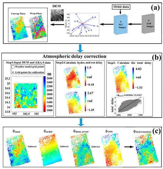
Figure 1.
Schematic diagram of atmosphere-corrected time-series InSAR integrated with the latest meteorological reanalysis data. (a) D-InSAR flow. (b) Atmospheric delay correction flow. In step 1, black circles indicate the location of the ERA-5 grid point at ~27 km and the background is a DEM. Gray scatter plots show the relationship between the atmospheric delay and elevation estimated by ERA-5. (c) Time-series analysis flow, where denotes the original phase, denotes the orbital error, denotes the DEM error, denotes the atmospheric delay, and is the deformation phase.
3. Test Sites and Datasets
3.1. Overview of the Study Area
As shown in Figure 2, the Yuxi Basin is located between 23°19′–24°53′N and 101°16′–103°09′E in Yunnan Province, China, belonging to the low-latitude plateau area in central Yunnan. Surrounded by mountains, the topography within the basin is flat (Figure 2b). The Yuxi Basin is a large sedimentary basin developed at the southern end of the north–south Puduhe fault zone with a basin length of approximately 23 km from north to south and a width of approximately 7–9 km. The complex fault structure in the basin, under the joint action of the Xiaojiang, Puduhe, Qujiang, and Yujiang fault zones, renders the region a high potential risk area with a high frequency and intensity of seismic activity in Yunnan. On 5 January 1970, a strong earthquake of magnitude 7.7 occurred in the Tonghai and Esan areas near the Qujiang fault zone. After the main earthquake, 12 aftershocks of magnitudes 5 to 5.9 occurred, causing serious landslides and mountain collapse. The earthquake caused serious human loss and property in the Yuxi area and affected an area of 4500 km2. The Yuxi sedimentary basin is dominated by alluvium, floodplain, and a small amount of slope deposits; the soils are characterized by a high water content, high compression, low bearing capacity, and strong consolidation and deformation. Yuxi City, southwest China, has scarce water resources and the city’s per capita water resources are only 12% of that of the province. According to a 2009 survey, the water level in Yuxi dropped by up to 3.6 m; excessive groundwater extraction caused serious ground subsidence in the area.
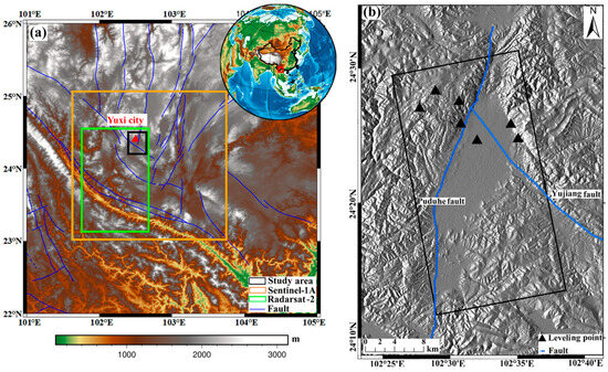
Figure 2.
(a) Topography map of the Yuxi Basin study area. The red box and solid black line in the upper right corner represent the study area, which is delineated in detail with topographic data in (a). (b) Outline of Yuxi city in (a) in the red triangular area; the background map is the topographic map from the SAR simulation. The black rectangular border is the scope of the test area.
Additionally, the climate of the region is characterized by complex changes and distinct dry and wet seasons. The rainy season is concentrated from May to October, with heavy rainstorms concentrated from June to August. The average annual precipitation ranges from 787.8 to 1000 mm. The strong topographic variations and combined effects of dry, warm, and wet air currents lead to a complex combination of stratified and turbulent delays in the Yuxi Basin.
3.2. Datasets
3.2.1. SAR Data
Two sets of C-band SAR data were selected to study atmospheric delay correction methods and ground deformation monitoring in the Yuxi Basin. Sentinel-1A and Radarsat-2 images were taken between 30 March 2020 and 19 August 2021; they were acquired at 11:09 and 23:19 UTC, respectively, which corresponds to local times of 19:09 and the following morning at 7:19. Among them, Sentinel-1A is a medium-resolution SAR satellite, which provides Earth observation data with a range direction of 2.3 m and an azimuth direction of 13.9 m. Radarsat-2 is a high-resolution SAR satellite, which provides Earth observation data with a range direction of 3 m and an azimuth direction of 3 m. We focused only on the hydrostatic and wet components because the liquid component was expected to be small and would only become significant for a saturated atmosphere; the ionospheric delays were assumed to be small for the C band [32]. To avoid baseline errors associated with masking of the tropospheric atmospheric signal, the perpendicular baselines of all the interferograms selected in this study were less than 200 m. Figure 3 shows the spatial and temporal baseline distributions. Table 2 presents basic information on the two SAR data sources.
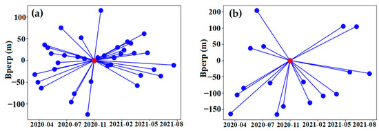
Figure 3.
Spatial-temporal baseline distribution of Sentinel-1A and Radarsat-2 data (red circle represents the reference image, blue circle represents the slave images, and blue lines indicate the formation of an interferogram). (a) Sentinel-1A. (b) Radarsat-2.

Table 2.
Basic parameters for the SAR data in the Yuxi study area.
3.2.2. ERA-5 Meteorological Reanalysis
ERA-5 is the latest generation of atmospheric reanalysis data after the ERA-I product from the ECMWF, which provides meteorological reanalysis data since 1979 and is updated in real time [42]. Compared to the 6-h time-sampled data provided by ERA-I and MERRA-2, ERA-5 provides a higher resolution in both time and space. Table 3 lists the relevant parameters. Hourly reanalysis of atmospheric physical parameters, with a horizontal resolution of 31 km, can be obtained by using ERA5 data; a higher temporal resolution minimizes errors owing to the time difference between the SAR acquisition and meteorological data. Another advantage of the ERA5 data is that the uncertainty estimates for all parameters are at 3-h intervals with a horizontal resolution of 62 km; therefore, these uncertainties can be used as reliability weights when interpolating atmospheric parameters, as well as to assess the confidence of the calculated atmospheric phase screens.

Table 3.
MERRA-2, ERA-I, and ERA-5 parameters.
4. Results
4.1. Effects of Hydrostatic Delay and Wet Delay
Tropospheric delays are divided into hydrostatic and wet delays; hydrostatic delay is related to pressure and temperature, which are relatively smooth in long-scale space and usually vary slowly with time, whereas the wet delay component depends on the variation in water vapor, which varies widely in time and space [42,55]. In this study, we used the ERA-5 and MERRA-2 meteorological reanalysis data to investigate the effects of hydrostatic and wet delays on atmospheric delays. We chose the interferogram with the shortest possible temporal baseline for quantitative analysis (24 d for the Sentinel-1A interferogram temporal baseline and 24 d for the Radarsat-2 interferogram temporal baseline) to avoid the effect of the deformation phase. Figure 4 shows the results. For the interferogram phase, the wet delay component accounted for a significantly larger fraction than the hydrostatic delay. Combined with the histograms in Figure 4, the correction effect of both meteorological reanalysis datasets on the hydrostatic delay was almost equal for both the Sentinel-1A and Radarsat-2 interferograms. For the Sentinel-1A interferograms, the average difference between the two methods was 0.27 rad (~0.12 cm). For the Radarsat-2 interferograms, the average difference between the two methods was only 0.14 rad (~0.06 cm). Although the two meteorological datasets had consistent corrections for the hydrostatic delay, there were still some differences in the correction effect of the two methods for different types of SAR data. This may have been caused by the difference in the acquisition times of the two SAR datasets because Sentinel-1A was acquired at 19:09 whereas Radarsat-2 was acquired at 07:19. This fully illustrates the existence of a certain stability in the hydrostatic delay within the time and space scales. The correction effect of the two meteorological reanalysis datasets was consistent. However, for the wet delay, as the tropospheric atmosphere contains water vapor (which has a small spatial scale, rapid time change, and strong randomness), the wet delay estimated by the two methods was different. For the Sentinel-1A interferogram, the average deviation in the wet delay, as calculated from the two meteorological reanalysis datasets, was 1.53 rad (~0.68 cm), with a maximum difference of 2.85 rad (~1.27 cm). For the Radarsat-2 interferogram, the average deviation in the wet delay obtained by the two methods was 4.25 rad (~1.89 cm); the maximum difference reached 4.75 rad (~2.12 cm). This showed that there were errors at approximately the centimeter level in the wet delay, which significantly limited the accuracy of the deformation solution. Therefore, although the hydrostatic delay component accounted for a larger proportion of the atmospheric component, the wet delay component was significantly more influential than the hydrostatic delay component in the interferograms.
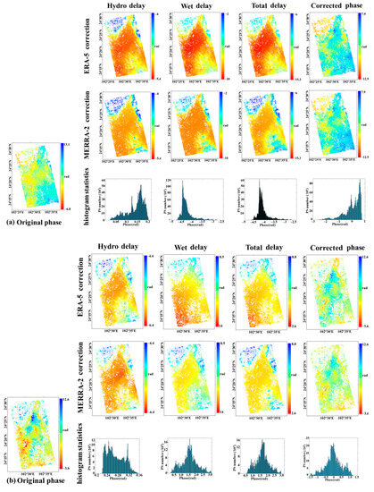
Figure 4.
Comparison of the atmospheric delay correction effects in Sentinel-1A and Radarsat-2. (a) Two types of meteorological reanalysis data were used to correct the atmospheric delay in Radarsat-2 (master = 20201101; slave = 20201008). The histogram counted the difference between the two methods for the hydrostatic delay, wet delay, and total delay. (b) Two types of meteorological reanalysis for the correction of atmospheric delay in Sentinel-1A (master = 20201104; slave = 20201011; the histogram counts the difference between the two methods for the hydrostatic delay, wet delay, and total delay).
To evaluate the improvement effects of the two methods on hydrostatic delay and wet delay, we counted the change in the phase STD of the interferogram before and after adopting the two methods. Considering the effects of orbit and DEM errors, for orbital errors, which are typically characterized as long-wavelength artifacts in the interferogram, this component can be easily confused with the long wavelength component in the atmospheric delay [15,45]. Unlike water vapor, temperature and pressure are smooth in space, leading to a better-resolved longer wavelength hydrostatic component [15]. We compared the degree of influence of the hydrostatic delay in the interferograms before and after the orbital error correction, as shown in Figure 5. We can see that the magnitude of the change in phase STD after hydrostatic delay correction is not large regardless of whether orbital error correction is performed. This is mainly due to the fact that the differential interference further reduces the weight of the hydrostatic delay.
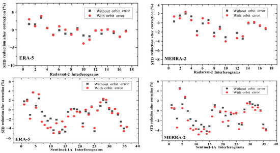
Figure 5.
Evaluation of the effect of orbital errors on the hydrostatic delay (Radarsat-2 interferograms in the first row and Sentinel-1A interferograms in the second row).
Therefore, we assumed that the residual component only contained the orbital error and the atmospheric delay, such that we could separate the orbital error according to polynomial plane fitting. We corrected the orbital error before comparing the phase STD before and after the atmospheric delay correction; therefore, the residual interferometric phase included the atmospheric delay and deformation phases. Theoretically, a lower STD for the interferometric phase indicates a more pronounced mitigation of atmospheric delay effects. According to the statistics of the phase STD of 17 Radarsat-2 interferograms, after the hydrostatic delay was removed by ERA-5, eight interferograms were improved with a maximum reduction of 3.85% and an average of 1.17%; the phase STD increased in nine interferograms, with an average increase of 1.05% and a maximum increase of 2.01%. However, after the wet delay was estimated and corrected by ERA-5, 10 interferograms were improved, with a maximum reduction of 37.95% and an average of 19.17%; seven interferograms showed an increase in the phase STD, with an average increase of 7.46% and a maximum increase of 17.34%. We also used MERRA-2 meteorological reanalysis data to evaluate the atmospheric delay correction of the Radarsa-2 data. After the removal of the hydrostatic delay by MERRA-2, seven interferograms were improved, with a maximum reduction of 1.37% and an average of 0.92%; 10 interferograms instead showed an increase in the phase STD, with an average increase of 1.59% and a maximum increase of 2.93%. However, after wet delay correction by MERRA-2, eight interferograms were improved with a maximum reduction of 34.82% and an average of 16.91%; nine interferograms increased the phase STD, with an average increase of 3.57% and a maximum increase of 6.56%. We also evaluated the atmospheric correction of 36 Sentinel-1A unwrapped interferograms by using ERA-5 and MERRA meteorological reanalysis data. The STD of 13 out of the 36 interferograms was reduced after ERA-5 correction for the hydrostatic delay, with a maximum reduction of 6.09% and an average of 1.55%, whereas the STD of 23 out of the 36 interferograms increased, with an average increase of 3.02% and a maximum increase of 6.14%. However, after the wet delay was estimated and corrected by ERA-5, 18 interferograms were improved, with a maximum reduction of 19.51% and an average of 8.88%. The STD of 18 interferograms increased, with an average increase of 4.56% and a maximum increase of 12.17%. After correction of the hydrostatic delay by MERRA-2, 11 interferograms were improved, with a maximum reduction of 4.39% and an average of 1.29%; 25 interferograms showed an increase in the phase STD, with an average increase of 2.49% and a maximum increase of 5.48%. After wet delay correction by MERRA-2, 15 interferograms were improved, with a maximum reduction of 32.36% and an average of 19.8%; 21 interferograms showed an increase in the phase STD, with an average increase of 6.26% and a maximum increase of 13.35%. By evaluating the robustness of the two reanalysis datasets in terms of hydrostatic delay and wet delay, we found that the effect of hydrostatic delay on both types of SAR data was small; the effect of hydrostatic delay in atmospheric delay could be ignored in practical applications. The wet delay dominated the interferogram; this delay component was related to the variation in the water vapor content in the air. ERA-5, with higher temporal and spatial resolutions, captured the wet delay better than MERRA-2. However, both reanalysis datasets misestimated the wet delay component, which, in turn, introduced larger atmospheric estimation errors. Therefore, when using meteorological reanalysis data to correct tropospheric delay, a comprehensive analysis of each interferogram must be performed before deciding whether to adopt it.
To measure the accuracy of estimating atmospheric delay from the ERA-5 meteorological reanalysis data used in this study, the phase STD before and after atmospheric correction of both the ERA-5 and MERRA-2 meteorological data was calculated [15]. Figure 6 and Table 4 present these results. Both meteorological reanalysis datasets had a certain improvement effect on the atmospheric delay in the Yuxi Basin, among which ERA-5 had a better effect on Radarsat-2 and Sentinel-1A interferogram correction; the average reduction in the phase STD reached 19.68 and 14.75%, respectively. The average reduction in the phase STD for the Radarsat-2 and Sentinel-1A interferograms was 19.14 and 9.8%, respectively, after using MERRA-2 to correct the two types of interferometric data. This shows that ERA-5 has high temporal and spatial resolution and can effectively estimate and correct locally varying atmospheric signals.

Figure 6.
Radarsat-2 and Sentinel-1A interferograms before and after total atmospheric delay correction. (a) Sentinel-1A. (b) Radarsat-2.

Table 4.
Statistical results for different atmospheric delay correction methods.
4.2. Vertical Stratification Delay and Turbulent Delay
As previously mentioned, corrections based on atmospheric delays are typically modeled separately for stratified and turbulent delays. The stratified delay is related to the terrain elevation and only affects mountainous areas with significant terrain variation, whereas the turbulent delay may be present in both mountainous and flat terrain. The classical PS-InSAR methods that use temporal and spatial filtering can only eliminate non-seasonal stochastic residuals, whereas topography-dependent stratified delays cannot be estimated [56,57]. The study area includes both the flat Yuxi Basin and mountainous areas with large topographic variations, such as the Xiaojiang fault zone on the east and west sides of the basin. By calculating the relationship between deformation and elevation, we found that the deformation signal was mainly distributed in artificial building areas for elevations within 1200–1550 m. Therefore, to avoid the topography-related deformation signal confusing the vertical stratification delay signal, only the area with an elevation greater than 1550 m was statistically analyzed in this study. We calculated the linear relationship between the interferograms before and after correction, as well as the local topography based on the SRTM DEM. Larger values of the linear coefficient |K| indicate a more significant atmospheric stratified delay; smaller values of |K| indicate the dominance of a turbulent delay.
Figure 7 shows that the stratified delay dominates the original interferogram (Figure 7a first row and Figure 7b first row); both the ERA-5 and linear methods can mitigate this atmospheric delay effect. There was a high agreement between the atmospheric delays estimated by the two methods, with a correlation coefficient of 0.73. The local correlation coefficients between the interferometric phase and topography were reduced from 6.32 rad/km (~2.81 cm/km) to 0.04 rad/km (~0.018 cm/km) and 1.18 rad/km (~1.25 cm/km), respectively, after the correction of the interferometric phase by the ERA-5 and linear model methods. However, when the turbulent delay dominated (Figure 7a, second row and Figure 7b, second row), the difference between the two methods for atmospheric delay improvement was evident, with a correlation coefficient of only 0.02. The STD of the interferometric phase changed from 1.96 to 2.0 and 1.29 rad after using the linear model and ERA-5, respectively. When the turbulent mixing delay dominated, the conventional linear model for the phase and elevation could only estimate the topography-dependent vertical stratification delay component of the atmospheric delay, but could not effectively estimate the turbulent mixing delay, which resulted in a serious underestimation of the atmospheric delay signal and even caused a degradation of the STD of the interference phase. In contrast, the ERA-5 reanalysis used real-time acquired meteorological elements, such as pressure, temperature, and relative humidity to invert the simulated values similar to the atmosphere through assimilation techniques, thus still partially mitigating the atmospheric delay in the interferometric phase. Figure 8 compares the correlation between the amount of STD change after correction with ERA-5 and the linear coefficient |K|. The improvement effect of ERA-5 was more notable when the stratified delay dominated (the larger the |K| coefficient).
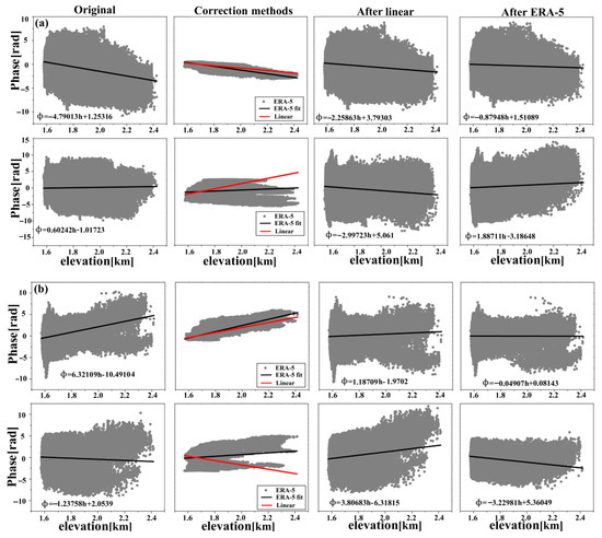
Figure 7.
Interferogram phase versus elevation before and after ERA-5 and linear model correction (black line indicates the linear relationship between atmospheric delay and elevation calculated by ERA-5). (a) Radarsat-2 phase and elevation relations before and after atmospheric correction (stratified delay dominates in the first row and turbulent mixing delay dominates in the second row). (b) Sentinel-1A phase and elevation relationship before and after atmospheric correction (stratified delay dominates in the first row and turbulent mixing delay in the second row).
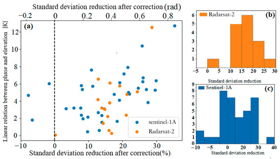
Figure 8.
(a) Variation in the phase STD with |K|; (b,c) frequency distribution of STD variation for 17 interferograms from Radarsat-2 and 36 interferograms from Sentinel-1A, respectively, after atmospheric correction.
4.3. TS-InSAR Analysis of the Yuxi Basin Based on ERA-5 Data
The ERA-5 atmospheric delay estimation method was applied to TS-InSAR deformation monitoring in the Yuxi Basin. As previously mentioned, ground subsidence is the main geological hazard in the Yuxi Basin. The subsidence area is mainly concentrated in urban building areas. Our TS-InSAR monitoring of subsidence in the Yuxi Basin also focused on the flat area of the basin and did not consider the stratified delay throughout the surrounding mountains. Therefore, after deducting the topographic phase, DEM error, and orbital error, we estimated and separated the atmospheric stratified delay effect from the interferometric phase by using ERA-5. For the deformation phase and residual turbulence delay phase, we used conventional temporal filtering to separate them and obtain the final deformation rate. We converted the LOS deformation rate in the vertical direction by using . Figure 9 shows the deformation rates for both data sources with ERA-5 atmospheric delay correction. Based on the overall deformation distribution, the deformation rates obtained from the inversion of the two data sources were consistent at the spatial scale. Ground subsidence in Yuxi is polycentrically clustered; three notable subsidence funnels (Zones A, B, and C) are distributed along the right side of the fault.
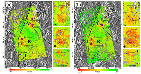
Figure 9.
Results for the vertical deformation velocity obtained from the Radarsat-2 and Sentinel-1A. Black triangles indicate the location of the leveling points; purple circles indicate subsidence villages. Black dashed lines indicate faults. (a) Vertical deformation velocity generated by Radarsat-2. (b) Vertical deformation velocity generated by Sentinel-1A.
Tangjiaying to Fengjing are center in Zone A of the subsidence funnel, forming a north–south elliptical subsidence surface; the surrounding areas, including Qingdui, Beicheng, Xiajing Village, and Hewangtun, have some degree of subsidence, with deformation rates mostly concentrated from –15 to 0 mm/a and a maximum deformation rate reaching –23.8 mm/a. Zone B has the widest and most uneven distribution of subsidence; the subsidence area covers several small subsidence centers. The subsidence surface is in the southwest–northeast direction, including Dayingjie Town, Gao Cang Town, Zhaowei Village, Taoyuan Village, and Masushu Village. The deformation rate mostly ranges from –17 to 0 mm/a; the maximum deformation rate reaches –32.2 mm/a. Zone B is also the largest subsidence area in this study, with the Lotus Pond floodplain fan to the west and floodplain skirt and alluvial terraces to the northeast; therefore, the soils in this area are characterized by a high water content, high compressibility, low bearing capacity, and strong consolidation deformation. The clay layer consolidates and compresses as the water pressure decreases, eventually causing ground settlement. Subsidence in this area may be preliminarily related to the over-exploitation of groundwater. Zone C is a small subsidence funnel located in the Puduhe fault zone. The subsidence trend has developed in the northeast direction, involving the Hele and Dongshan villages, gradually connecting with Zone B. The deformation rate mostly ranges from –12 to 0 mm/a; the maximum deformation rate reaches –19.9 mm/a.
5. Discussion
5.1. Typical Regional Time-Series Analysis
To examine the time-series evolution of subsidence zones A, B, and C, one PS point near each of the six corresponding villages in Figure 9 was selected for the time-series analysis in this study, as shown in Figure 10. The correlation coefficients of the PS point deformation time-series for the six typical subsidence zones calculated by Sentinel-1A and Radarsat-2 were 0.723, 0.684, 0.797, 0.823, 0.757, and 0.536, with an average error of 6.34 mm/a in the deformation rates. Considering the differences in the temporal and spatial resolutions of the datasets, we assumed that the two results were consistent, which also indicates the validity of the atmospheric delay of ERA-5 for TS-InSAR. In terms of the deformation time-series, A and B, located in Hongta District, were still the most serious areas of subsidence. From April 2020 to February 2021, the cumulative subsidence in Tangjiaying, Fengjing, Beihucun, and Taoyuancun was 27.73, 29.48, 24.76, and 35.49 mm, respectively. Hongta District was affected by a dry climate throughout the year. Residents mainly rely on the local “three lakes” for their water supply. However, in 2013, the water level of Fuxian Lake reached a historical low of 1720.04 m. The water level of Xinyun Lake dropped 8 cm from the previous year, 7 cm lower than the prescribed storage level. The water depth of Qilu Lake was only 1.26 m, which made it impossible to supply water. Therefore, the extraction of groundwater has become key to meeting the needs of local residents. Recently, the urban expansion of Hongta District has intensified the ground load. With the massive exploitation of groundwater from deep wells, the groundwater level in the area has declined, causing widespread subsidence in the area. From February 2021 onward, the subsidence rate in the three regions slowed significantly and even appeared to rise, mainly due to the development of local water diversion projects, as well as the arrival of the rainy season. In contrast, groundwater was fully recharged, the water level gradually recovered and rose, and ground subsidence was effectively controlled. Additionally, a small subsidence funnel was found in Area C. Considering that the area is located in a suburban area with a small resident population base, we initially speculate that the main cause of subsidence in the area was control from the Puduhe fault zone to the west.

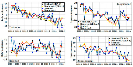
Figure 10.
PS point time-series displacement (the exact locations of the six villages are marked with purple circles in Figure 9.
5.2. Response Relationship between Ground Subsidence and Rainfall
In addition to local subsidence caused by groundwater pumping, the seasonal decline and recovery of the groundwater level caused by rainfall has also caused corresponding fluctuations in the vertical ground deformation. The climate of Yuxi City, Yunnan Province, is characterized by complex changes and distinct dry and wet seasons. The rainy season is from May to October; single-point rainstorms occur from June to August. Based on this, this study applied rainfall data from the NASA Global Precipitation Measurement Mission (GPM) website for the same period and analyzed the time-series curve of the PS point deformation variables, as shown in Figure 11. Surface deformation in area A is mostly affected by rainfall. From March 2020 to August 2020, the rainfall increased steeply from 22.57 to 214.47 mm; the groundwater level was partially restored and the deformation curve in this area showed a notable elevation. The deformation rate reached +1.75 mm/month. From September 2020 to March 2021, with the arrival of the dry season, the average monthly rainfall decreased to 19.39 mm. With further groundwater exploitation, the groundwater level continued to decrease, and the soil-bearing layer consolidated and compacted with the decrease in the water pressure. The inelastic consolidation of the aquifer played a leading role in the deformation process, which finally led to continuous ground subsidence; the deformation rate reached –2.88 mm/month at this stage. The surface deformation in Zone B was also influenced by seasonal rainfall. From March 2020 to August 2020, rainfall increased steeply from 19.69 to 208.37 mm; the deformation curve in this area showed a significant rise, and the deformation rate reached +0.89 mm/month. From September 2020 to March 2021, with the arrival of the dry season, the average monthly rainfall decreased to 32.65 mm; the corresponding surface sedimentation rate increased significantly, reaching –2.91 mm/month. The deformation variables in Zone C were also generally consistent with the seasonal rainfall, but the correlation was low; the decrease in rainfall from March 2020 to August 2020 did not trigger significant subsidence in the area. This is because Area C is located in a sparsely populated suburban area with less groundwater extraction than Zones A and B. Deformation was mainly controlled by the Puduhe fault zone in the west.

Figure 11.
Relationship between deformation and rainfall response in zones A, B. (a) Relationship between deformation and rainfall response in Zone A (first row represents the deformation velocity of Radarsat-2; the second row represents the deformation velocity of Sentinel-1A). (b) Relationship between deformation and rainfall response in zone B (first row represents the deformation velocity of Radarsat-2; the second row represents the deformation velocity of Sentinel-1A). (c) Relationship between deformation and rainfall response in zone C (first row represents the deformation velocity of Radarsat-2; second row represents the deformation velocity of Sentinel-1A).
5.3. Correlation Analysis between Deformation and Fault
Tectonic movements also have a high correlation with the subsidence distribution in the Yuxi area. Based on the distribution of deformation rates in Figure 9, subsidence zones A, B, and C are all on the western side of the Puduhe Rift Zone. Combined with the analysis of historical information, the Puduhe fault zone is an active fault zone with a near north–south trend. The eastern zone consists of the Dalongkou Formation tuffs while the western zone consists of the Meidang Formation slate and the Dalongkou Formation tuff. As tuff from the Dalongkou Formation recoil above the slate in the Meidan Formation, they are mis-shifted by small east–west faults (Yujiang fault zone) at Lotus Pond and Jiulong Pond. After experiencing many tectonic movements, the east plate has strongly subsided while the west plate has uplifted. To investigate the deformation patterns on both sides of the fault zone, we drew three profiles, A-A’, B-B’, and C-C’, through the Puduhe fault zone in zones A, B, and C, respectively. The three profiles traverse Fengjing, Beihu Village, and Hele Village, as shown in Figure 12. The west side of the fault zone in Zone C is mainly uplifted: the farther from the fault zone, the more notable the uplift. The east side exhibits severe subsidence; the subsidence rate near Hele village reaches –20 mm/yr. Small earthquakes of magnitudes 2.5–6 often occur around the Puduhe fault zone. Tectonic movements are frequent, which also indicates that there is some correlation between ground subsidence and tectonic movement in Zone C. Zone A is affected by both the Puduhe fault zone and the east–west Yujiang fault zone that cuts the Puduhe fault zone, which causes a rising and falling of the fault blocks on both sides. However, we also note in Figure 12 that there is no notable deformation boundary in Zone A under the action of the Yujiang fault zone, which indicates that tectonic movement is not highly correlated with deformation in this area. The main reason for deformation is related to the change in the local groundwater level.
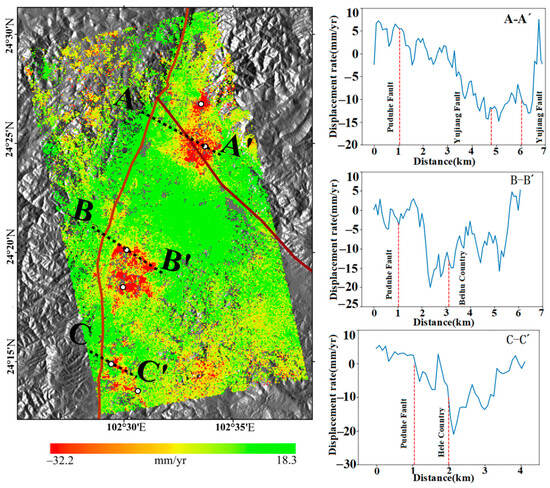
Figure 12.
Deformation profiles of the existing fault zone near the subsidence area (AA’, BB’, and C-C’ shown in this figure).
5.4. Leveling Monitoring Data Validation
Yuxi leveling monitoring data further validated the reliability and effectiveness of the ERA-5 atmospheric correction method for TS-InSAR surface deformation monitoring. For each leveling monitoring point, we selected the nearest PS point deformation rate value to the leveling for comparison and used the leveling measurement as the true value. Table 5 lists the statistical results. There are notable differences between the traditional StaMPS method and leveling measurements, whereas the ground displacement with ERA-5 atmospheric correction was more similar to the leveling measurements.

Table 5.
Comparison of PS point deformation rate and leveling measurement data.
For Radarsat-2, the average RMSE between the seven-level data and the conventional StaMPS measurements was 4.84 mm/a. After improvement with ERA-5, the average RMSE was 2.53 mm/a. For the lower-resolution Sentinel-1A, owing to dense vegetation and steep terrain in the northwest part, the PS points were sparsely distributed in this area; only five matching PS points were found in the level measurement. The average RMSE between the five-level data and the conventional StaMPS measurements was 3.92 mm/a whereas the average RMSE was 3.89 mm/a after ERA-5 improvement, which indicates that ERA-5 is more effective at improving the Radarsat-2 data with a higher spatial resolution. Additionally, based on the RMSE of the PS points and level points, the correction magnitude of the three leveling measurement points (A01, A02, and A03) located in mountainous areas was significantly larger than that of flat urban areas (A04, A05, and A06) after adopting ERA-5. This is because the mountainous area is affected by a stratified delay, which can be effectively removed using the ERA-5 method. However, for flat urban areas, ERA-5 was not effective at capturing small changes in the atmosphere owing to the dominance of small-scale turbulent delays; therefore, the improvement was not evident.
6. Conclusions
In this study, two types of C-band InSAR data, Sentinel-1A and Radarsat-2, were used as examples to evaluate the capability of the latest meteorological reanalysis ERA-5 data for atmospheric delay correction. A TS-InSAR processing method based on ERA-5 was developed and applied to InSAR surface deformation monitoring in the Yuxi Basin, Yunnan Province, for the first time. Hydrostatic delay varied slowly with time and was negligible in this atmospheric delay correction study. The two meteorological delay reanalysis datasets had comparable effects on hydrostatic delay correction. The wet delay was the main influencing factor in atmospheric delay. Improvements to the Sentinel-1A and Radarsat-2 interferogram phase STD after atmospheric delay correction by ERA-5 were 14.75 and 19.68%, respectively, which was better than that of the MERRA-2 reanalysis data. Additionally, this study also focused on exploring the estimation of stratified delay by using the ERA-5 method and comparing it with the traditional linear method. ERA-5 can effectively estimate the topography-dependent vertical stratification delay for a significant correlation between phase and elevation; the correlation with the stratification delay estimated by the linear method was 0.73. We performed a time-series analysis of the deformation points. The significant atmospheric effects in mountainous areas led to uncertainty in the displacement results compared to flat terrain in urban areas, where displacement occurs. Corrections using the atmospheric reanalysis information can yield results consistent with the leveling measurements. We also discussed interferograms dominated by turbulent delays, which are not correlated with the topography; neither linear nor ERA-5 methods were applicable to them. Meanwhile, meteorological reanalysis data have low spatial and temporal resolution compared to the time-series interferograms. The accuracy of the model output meteorological parameters requires further validation and improvement.
We applied the ERA-5 method to TS-InSAR deformation monitoring in Yuxi Basin, Yunnan Province. The results of our study indicate that there are three distinct subsidence centers in Yuxi. The overexploitation of groundwater is the main cause of surface subsidence. A joint analysis of the deformation time-series with monthly rainfall data showed a significant correlation between subsidence and reduced rainfall or lower groundwater levels. Additionally, the distribution of active fault zones also influences the formation of subsidence surfaces. Yuxi City is located on the east side of an active fault zone, where small earthquakes are frequent. To avoid geological disasters, such as landslides and ground collapse caused by geological formations, we will continue to monitor the evolution of ground subsidence in the Yuxi Basin by combining multiple TS-InSAR techniques to ensure the most effective risk mitigation strategies.
Author Contributions
Conceptualization, S.G.; methodology, S.G. and X.Z.; software, S.G. and W.W.; validation, S.G.; formal analysis, S.G.; investigation, S.G., F.L. and X.Z.; resources, S.G, X.Y. and Y.L.; data curation, S.G., S.Z. and Y.Z.; writing—original draft preparation, S.G.; writing—review and editing, S.G. and X.Y.; visualization, S.G.; supervision, X.Z.; project administration, X.Z.; funding acquisition, X.Z. All authors have read and agreed to the published version of the manuscript.
Funding
This research was funded by the National Natural Science Foundation of China (No: 42161067).
Data Availability Statement
The data used to support the findings of this study are available from the corresponding author upon request.
Acknowledgments
We thank ESA for the Sentinel-1A satellite data and corresponding precision orbital data, the Canadian Space Agency for the Radarsat-2 satellite data, ECMWF for the ERA-5 meteorological reanalysis, NASA Goddard Space Flight Center for the MERRA-2 meteorological reanalysis, and the University of Hawaii for the General Mapping Tool (GMT).
Conflicts of Interest
The authors declare no conflict of interest.
References
- Chaussard, E.; Wdowinski, S.; Cabral-Cano, E.; Amelung, F. Land subsidence in central Mexico detected by ALOS InSAR time-series. Remote Sens. Environ. 2014, 140, 94–106. [Google Scholar] [CrossRef]
- Calderhead, A.I.; Martel, A.; Alasset, P.-J.; Rivera, A.; Garfias, J. Land subsidence induced by groundwater pumping, monitored by D-InSAR and field data in the Toluca Valley, Mexico. Can. J. Remote Sens. 2010, 36, 9–23. [Google Scholar] [CrossRef]
- Yang, C.; Lv, S.; Hou, Z.; Zhang, Q.; Li, T.; Zhao, C. Monitoring of Land Subsidence and Ground Fissure Activity within the Su-Xi-Chang Area Based on Time-Series InSAR. Remote Sens. 2022, 14, 903. [Google Scholar] [CrossRef]
- Cigna, F.; Tapete, D. Satellite InSAR survey of structurally-controlled land subsidence due to groundwater exploitation in the Aguascalientes Valley, Mexico. Remote Sens. Environ. 2021, 254, 112254. [Google Scholar] [CrossRef]
- Hernandez-Marin, M.; Pacheco-Martinez, J.; Ramirez-Cortes, A.; Burbey, T.J.; Ortiz-Lozano, J.A.; Zermeño-de-Leon, M.E.; Guinzberg-Velmont, J.; Pinto-Aceves, G. Evaluation and analysis of surface deformation in west Chapala basin, central Mexico. Environ. Earth Sci. 2014, 72, 1491–1501. [Google Scholar] [CrossRef]
- Ojha, C.; Werth, S.; Shirzaei, M. Recovery of aquifer-systems in southwest US following 2012–2015 drought: Evidence from InSAR, GRACE and groundwater level data. J. Hydrol. 2020, 587, 16. [Google Scholar] [CrossRef]
- Bayuaji, L.; Sumantyo, J.T.S.; Kuze, H. ALOS PALSAR D-InSAR for land subsidence mapping in Jakarta, Indonesia. Can. J. Remote Sens. 2010, 36, 1–8. [Google Scholar] [CrossRef]
- Herrera-García, G.; Ezquerro, P.; Tomás, R.; Béjar-Pizarro, M.; López-Vinielles, J.; Rossi, M.; Mateos, R.M.; Carreón-Freyre, D.; Lambert, J.; Teatini, P.; et al. Mapping the global threat of land subsidence. Science 2021, 371, 34–36. [Google Scholar] [CrossRef]
- Ganas, A.; Marinou, A.; Anastasiou, D.; Paradissis, D.; Papazissi, K.; Tzavaras, P.; Drakatos, G. GPS-derived estimates of crustal deformation in the central and north Ionian Sea, Greece: 3-yr results from NOANET continuous network data. J. Geodyn. 2013, 67, 62–71. [Google Scholar] [CrossRef]
- Savage, J.C.; Church, J.P.; Prescott, W.H. Geodetic measurement of deformation in Owens Valley, California. Bull. Seismol. Soc. Am. 1975, 65, 865–874. [Google Scholar]
- Fialko, Y.; Sandwell, D.; Simons, M.; Rosen, P. Three-dimensional deformation caused by the Bam, Iran, earthquake and the origin of shallow slip deficit. Nature. 2005, 435, 295–299. [Google Scholar] [CrossRef] [PubMed]
- Massonnet, D.; Briole, P.; Arnaud, A. Deflation of Mount Etna monitored by spaceborne radar interferometry. Nature. 1995, 375, 567–570. [Google Scholar] [CrossRef]
- Botey i Bassols, J.; Vàzquez-Suñé, E.; Crosetto, M.; Barra, A.; Gerard, P. D-InSAR monitoring of ground deformation related to the dewatering of construction sites. A case study of Glòries Square, Barcelona. Eng. Geol. 2021, 286, 106041. [Google Scholar] [CrossRef]
- Brasca Merlín, A.; Solarte, A.; Bellis, L.M.; Carignano, C.; Cioccale, M.; Delgado, M.; Scavuzzo, M.; Argañaraz, J.P. DInSAR and statistical modeling to assess landslides: The case study of Sierras Chicas (central Argentina). J. S. Am. Earth Sci. 2021, 108, 10, 103179. [Google Scholar] [CrossRef]
- Bekaert, D.P.S.; Walters, R.J.; Wright, T.J.; Hooper, A.J.; Parker, D.J. Statistical comparison of InSAR tropospheric correction techniques. Remote Sens. Environ. 2015, 170, 40–47. [Google Scholar] [CrossRef]
- Doin, M.P.; Lasserre, C.; Peltzer, G.; Cavalie, O.; Doubre, C. Corrections of stratified tropospheric delays in SAR interferometry: Validation with global atmospheric models. J. Appl. Geophys. 2009, 69, 35–50. [Google Scholar] [CrossRef]
- Ferretti, A.; Prati, C.; Rocca, F. Permanent Scatterers in SAR Interferometry. IEEE Trans. Geosci. Remote Sens. 2001, 39, 8–20. [Google Scholar] [CrossRef]
- Haji-Aghajany, S.; Amerian, Y. Atmospheric phase screen estimation for land subsidence evaluation by InSAR time series analysis in Kurdistan, Iran. J. Atmos. Sol. Terr. Phys. 2020, 205, 8. [Google Scholar] [CrossRef]
- Schmidt, D.A.; Bürgmann, R. Time-dependent land uplift and subsidence in the Santa Clara valley, California, from a large interferometric synthetic aperture radar data set. J. Geophys. Res. 2003, 108, 1142–1153. [Google Scholar] [CrossRef]
- Liu, P.; Li, Q.; Li, Z.; Hoey, T.; Liu, G.; Wang, C.; Hu, Z.; Zhou, Z.; Singleton, A. Anatomy of Subsidence in Tianjin from Time Series InSAR. Remote Sens. 2016, 8, 266. [Google Scholar] [CrossRef]
- Qu, F.F.; Qin, Z.; Zhong, L.; Zhao, C.Y.; Yang, C.; Zhang, J. Land subsidence and ground fissures in Xi’an, China 2005–2012 revealed by multi-band InSAR time-series analysis. Remote Sens. Environ. 2014, 155, 366–376. [Google Scholar] [CrossRef]
- Berardino, P.; Fornaro, G.; Lanari, R.; Sansosti, E. A new algorithm for surface deformation monitoring based on small baseline differential SAR interferograms. IEEE Trans. Geosci. Remote Sens. 2002, 40, 2375–2382. [Google Scholar] [CrossRef]
- Li, Z.W.; Cao, Y.M.; Wei, J.C.; Duan, M.; Wu, L.X.; Hou, J.X.; Zhu, J.J. Time-series InSAR ground deformation monitoring: Atmospheric delay modeling and estimating. Earth Sci. Rev. 2019, 192, 258–284. [Google Scholar] [CrossRef]
- Gomba, G.; González, F.R.; Zan, F.D. Ionospheric phase screen compensation for the Sentinel-1 TOPS and ALOS-2 ScanSARmodes. IEEE Trans. Geosci. Remote Sens. 2017, 55, 223–235. [Google Scholar] [CrossRef]
- Liang, C.; Agram, P.; Simons, M.; Fielding, E.J. Ionospheric Correction of InSAR Time Series Analysis of C-Band Sentinel-1 TOPS Data. IEEE Trans. Geosci. Remote Sens. 2019, 57, 6755–6773. [Google Scholar] [CrossRef]
- Hanssen, R.F. Radar Interferometry: Data Interpretation and Error Analysis; Kluwer Academic Publishers: Dordrecht, The Netherlands, 2001; Volume 2001, pp. 161–196. [Google Scholar] [CrossRef]
- Wang, Y.Q.; Chang, L.; Feng, W.P.; Samsonov, S.V.; Zheng, W.J. Topography-correlated atmospheric signal mitigation for InSAR applications in the Tibetan plateau based on global atmospheric models. Int. J. Remote Sens. 2021, 42, 4361–4379. [Google Scholar] [CrossRef]
- Raucoules, D.; Cozannet, G.L.; Wppelmann, G.; Michele, M.D.; Marcos, M. High nonlinear urban ground motion in Manila (Philippines) from 1993 to 2010 observed by DInSAR: Implications for sea-level measurement. Remote Sens. Environ. 2013, 139, 386–397. [Google Scholar] [CrossRef]
- Tang, W.; Yuan, P.; Liao, M.; Balz, T. Investigation of Ground Deformation in Taiyuan Basin, China from 2003 to 2010, with Atmosphere-Corrected Time Series InSAR. Remote Sens. 2018, 10, 9. [Google Scholar] [CrossRef]
- Wicks, C.W. Magmatic activity beneath the quiescent Three Sisters volcanic center, central Oregon Cascade Range, USA. Geophys. Res. Lett. 2002, 29, 26–1–26–4. [Google Scholar] [CrossRef]
- Béjar-Pizarro, M.; Socquet, A.; Armijo, R.; Carrizo, D.; Genrich, J.; Simons, M. Andean structural control on interseismic coupling in the North Chile subduction zone. Nature Geosci. 2013, 6, 462–467. [Google Scholar] [CrossRef]
- Bekaert, D.P.S.; Hooper, A.; Wright, T.J. A spatially variable power law tropospheric correction technique for InSAR data. J. Geophys. Res. 2015, 120, 1345–1356. [Google Scholar] [CrossRef]
- Li, Z.W.; Ding, X.L.; Liu, G.X. Modeling atmospheric effects on InSAR with meteorological and continuous GPS observations: Algorithms and some test results. J. Atmos. Solar-Terrestrial Phys. 2004, 66, 907–917. [Google Scholar] [CrossRef]
- Li, Z.H.; Muller, J.P.; Cross, P.A.; Fielding, E.J. Interferometric synthetic aperture radar (InSAR) atmospheric correction: GPS, Moderate Resolution Imaging Spectroradiometer (MODIS), and InSAR integration. J. Geophys. Res. 2005, 110, B03410. [Google Scholar] [CrossRef]
- Foster, J.; Brooks, B.; Cherubini, T.; Shacat, C.; Businger, S.; Werner, C.L. Mitigating atmospheric noise for InSAR using a high resolution weather model. Geophys. Res. Lett. 2006, 33, 16. [Google Scholar] [CrossRef]
- Lu, Z.; Freymueller, J.; Gong, J.; Lee, C.; Meyer, W. Measurement and interpretation of subtle deformation signals at Unimak Island from 2003 to 2010 using weather model-assisted time series InSAR. J. Geophys. Res. 2015, 120, 1175–1194. [Google Scholar] [CrossRef]
- Nico, G.; Tome, R.; Catalao, J.; Miranda, P.M.A. On the Use of the WRF Model to Mitigate Tropospheric Phase Delay Effects in SAR Interferograms. IEEE Trans. Geosci. Remote Sens. 2011, 49, 4970–4976. [Google Scholar] [CrossRef]
- Li, Z.W.; Xu, W.B.; Feng, G.C.; Hu, J.; Wang, C.C.; Ding, X.L.; Zhu, J.J. Correcting atmospheric effects on InSAR with MERIS water vapour data and elevation-dependent interpolation model. Geophys. J. Int. 2012, 189, 898–910. [Google Scholar] [CrossRef]
- Liang, C.; Jin, S.; He, X. Assessment of InSAR Atmospheric Correction Using Both MODIS Near-Infrared and Infrared Water Vapor Products. IEEE Trans. Geosci. Remote Sens. 2014, 52, 5726–5735. [Google Scholar] [CrossRef]
- Parker, A.L.; Biggs, J.; Walters, R.J.; Ebmeier, S.K.; Lu, Z. Systematic assessment of atmospheric uncertainties for InSAR data at volcanic arcs using large-scale atmospheric models: Application to the Cascade volcanoes, United States. Remote Sens. Environ. 2015, 170, 102–114. [Google Scholar] [CrossRef]
- Jolivet, R.; Grandin, R.; Lasserre, C.; Doin, M.P.; Peltzer, G. Systematic InSAR tropospheric phase delay corrections from global meteorological reanalysis data. Geophys. Res. Lett. 2011, 38, 17. [Google Scholar] [CrossRef]
- Hu, Z.; Mallorquí, J.J. An Accurate Method to Correct Atmospheric Phase Delay for InSAR with the ERA5 Global Atmospheric Model. Remote Sens. 2019, 11, 1969. [Google Scholar] [CrossRef]
- Smith, E.K.; Weintraub, S. The constants in the equation for atmospheric refractive index at radio frequencies. Proc. IRE 1953, 41, 1035–1037. [Google Scholar] [CrossRef]
- Zhu, B.Y.; Li, J.C.; Tang, W. Correcting InSAR Topographically Correlated Tropospheric Delays Using a Power Law Model Based on ERA-Interim Reanalysis. Remote Sens. 2017, 9, 765. [Google Scholar] [CrossRef]
- Jolivet, R.; Agram, P.S.; Lin, N.Y.; Simons, M.; Doin, M.P.; Peltzer, G.; Li, Z.H. Improving InSAR geodesy using global atmospheric models. J. Geophys. Res. 2014, 119, 2324–2341. [Google Scholar] [CrossRef]
- Saastamoinen, J.H. Atmospheric Correction for the Troposphere and the Stratosphere in Radio Ranging Satellites. Use Artifical Satell. Geod. 1972, 15, 247–251. [Google Scholar] [CrossRef]
- Dong, J.; Zhang, L.; Liao, M.S.; Gong, J.Y. Improved correction of seasonal tropospheric delay in InSAR observations for landslide deformation monitoring. Remote Sens. Environ. 2019, 233, 111370. [Google Scholar] [CrossRef]
- Yagüe-Martínez, N.; Prats-Iraola, P.; González, F.R.; Brcic, R.; Shau, R.; Geudtner, D.; Eineder, M.; Bamler, R. Interferometric processing of Sentinel-1 TOPS data. IEEE Trans. Geosci. Remote Sens. 2006, 54, 2220–2234. [Google Scholar] [CrossRef]
- Kampes, B.; Usai, S. Doris: The Delft object-oriented radar interferometric software. In Proceedings of the 2nd ITC ORS Symposium, Enschede, The Netherlands, 16–20 August 1999. [Google Scholar]
- Hooper, A.; Zebker, H.; Segall, P.; Kampes, B. A New Method for Measuring Deformation on Volcanoes and Other Natural Terrains Using InSAR Persistent Scatterers. Geophys. Res. Lett. 2004, 31, L23611. [Google Scholar] [CrossRef]
- Hooper, A.; Segall, P.; Zebker, H. Persistent scatterer interferometric synthetic aperture radar for crustal deformation analysis, with application to Volcán Alcedo, Galápagos. J. Geophys. Res. 2007, 112, B07407. [Google Scholar] [CrossRef]
- Hooper, A.; Zebker, H.A. Phase unwrapping in three dimensions with application to InSAR time series. J. Opt. Soe. Am. A 2007, 24, 2737–2747. [Google Scholar] [CrossRef]
- Chen, C.W.; Zebker, H. Phase unwrapping for large SAR interferograms: Statistical segmentation and generalized network models. IEEE Trans. Geosci. Remote Sens. 2002, 40, 1709–1719. [Google Scholar] [CrossRef]
- Hooper, A.; Bekaert, D.; Spaans, K.; Arikan, M. Recent advances in SAR interferometry time series analysis for measuring crustal deformation. Tectonophysics 2012, 514–517, 1–13. [Google Scholar] [CrossRef]
- Hanssen, R.; Bamler, R. Evaluation of Interpolation Kernels for SAR Interferometry. IEEE Trans. Geosci. Remote Sens. 1999, 37, 318–321. [Google Scholar] [CrossRef]
- Ferretti, A.; Prati, C.; Rocca, F. Nonlinear subsidence rate estimation using permanent scatterers in differential SAR interferometry. IEEE Trans. Geosci. Remote Sens. 2000, 38, 2202–2212. [Google Scholar] [CrossRef]
- Fattahi, H.; Amelung, F. InSAR bias and uncertainty due to the systematic and stochastic tropospheric delay. J. Geophys. Res. 2015, 120, 8758–8773. [Google Scholar] [CrossRef]
Publisher’s Note: MDPI stays neutral with regard to jurisdictional claims in published maps and institutional affiliations. |
© 2022 by the authors. Licensee MDPI, Basel, Switzerland. This article is an open access article distributed under the terms and conditions of the Creative Commons Attribution (CC BY) license (https://creativecommons.org/licenses/by/4.0/).
