Abstract
Distributed scatterers (DSs) are necessary to increase point density in multi-temporal InSAR (MT-InSAR) monitoring. The identification of homogeneous pixels (HPs) is the first and key step for DS processing to overcome the low signal-to-noise ratio condition. Since multi-polarization data are good at describing geometrical structures and dielectric properties of ground objects, they have been applied for HP identification. However, polarimetric information is not enough for identifying areas with similar ground objects but different deformation. We propose a novel DS preprocessing algorithm based on polarimetric interferometric homogeneous pixel (PIHP) identification. Firstly, a novel Polarimetric InSAR (PolInSAR) similarity that combines polarimetric intensity, interferometric coherence, and phase is proposed, which is readily available in multi-baseline and multi-polarization data and flexible by controlling weighting factors. Secondly, based on the binary partition tree (BPT) framework, object-orientated multi-scale PIHP identification is achieved, which is suitable for complex deformation scenes. Tested with simulated quad-polarization data, our method shows improvement in phase quality and point density, especially in the deformed areas, compared with the traditional HP identification method based on the polarimetric homogeneity (PolHom) test and the method with ground object type map. Tested with 30 quad-polarization Radarsat-2 images over Kilauea Volcano, the point density of our method is three times higher than that of the PolHom test in vegetation areas. Our method is proven to be more sensitive and mechanically more advanced to homogeneous pixels identification than the traditional ones, which is helpful for phase optimization, spatial enlargement of monitoring points, and stability of the MT-InSAR algorithm.
1. Introduction
Multi-temporal interferometry synthetic aperture radar (MT-InSAR) is a popular technique for ground deformation measurement with the advantages of millimeter accuracy and long time-series surface monitoring ability [1,2,3,4,5,6,7,8]. As the complexity of the practical scenes increases, the sparse monitoring points in low-coherence areas have become the bottleneck restricting the application of MT-InSAR. In the past few years, the comprehensive use of persistent scatterers (PSs) and distributed scatterers (DSs) has become an effective method to improve the point density in full-resolution monitoring [8,9,10,11,12,13]. The essence of such methods is to preprocess the DSs into the PSs, so as to increase the input points of PSI technique and the details of the deformation results.
Different from the PS with high scattering stability in the whole time series, DS refers to a group of adjacent pixels sharing a similar scattering mechanism with many small scatterers of similar size [9,10]. When the resolution of the SAR image is several meters, the areas covered by vegetation, debris, and even the rough artificial targets can be defined as DSs, which are easily decorrelated in time-series measurement [10]. To reduce the impact of decorrelation, a relatively strong common scatterer should be found by the phase optimization of a certain number of neighboring pixels, namely the homogeneous pixels (HPs) [14,15,16]. Accordingly, the preprocessing of DS usually identifies the HPs first and then optimizes the interferometric phase with such HPs.
There are many HP identification methods, whether using single-polarization data or multi-polarization data. The HPs obtained by single-polarization methods are considered the statistical homogeneous pixels (SHPs) [17]. As the name implies, the SHP is identified by the statistical test between the center pixel and the remaining pixels within the predefined window one by one. Different testing strategies have been proposed for single-polarization HP selection, including non-parametric tests (such as the two-sample Kolmogorov–Smirnov test [9] and Anderson–Darling test [18,19]) and parametric tests (such as the amplitude mean test [17] and the amplitude variance test [20]). Obviously, the above strategies have two disadvantages. One is that the methods only use the intensity/amplitude information without the interferometric phase information. The other is that single-polarization data cannot describe the physical structure attributes of ground objects, leading to an inaccurate HPs selection.
Considering the advantage of multi-polarization data in describing the physical structures and dielectric properties of ground objects [21], HP selection methods based on multi-polarization data have inevitably been proposed [22,23]. It has been shown that the point density obtained by the multi-polarization data is higher than that of the single-polarization data. Polarimetric homogeneous pixels (PHPs) were first proposed by using a likelihood ratio test, similar to the single-polarization method, to determine the polarimetric stationarity [22]. The PHPs obtained by this method are the neighboring pixels with the same distribution of the polarimetric covariance matrices. Additionally, the similarity between PHPs can be characterized by clustering the interconnected pixels with similar scattering properties, which are assessed by the Cloude-Pottier eigenvalue-eigenvector decomposition with the Wishart distance measure [23].
In application, it is common that the ground objects have the same scattering properties but different differential interferometric phases. However, the above methods only use the polarimetric statistical information without considering the polarimetric interferometric SAR (PolInSAR) information. There is no doubt that such methods are unqualified to identify the accurate HPs, which should have not only similar backscattering properties but also consistent interferometric phases.
However, in terms of the existing polarimetric interferometric homogeneous pixels (PIHPs) identification, there are still many limitations for the similarity measurement in the application of multi-baseline PolInSAR data.
- (1)
- First, it is inappropriate to use the PolInSAR coherency matrix with a large data dimension, which seriously increases the burden of similarity measurement [24]. As mentioned in [25], the full-rank matrix for the similarity measurement should be filtered or regularized by at least 3N independent samples when the number of acquisitions is N. Thus, whether it is long time-series observation or point or line target monitoring; this method is not suitable due to the large computational burden.
- (2)
- Second, the similarity test indicator based on the PolInSAR coherency matrix is a trade-off between interferometry and polarimetry, of which the weight assignment is uncontrollable, and some undesirable pixels are selected [26].
- (3)
- Third, the observation geometries of multi-baseline PolInSAR data are different, leading to the uncertainty of the time-series similarity indicator [25]. In addition, the PIHP identification based on the hypothesis statistic test relies on the rationality of the statistical model [27]. An unreasonable statistical model will lead to incorrect PIHP extraction. Moreover, the similarity test between pixels is sensitive due to the inherent speckle noise in PolSAR images, of which the error can be amplified with the increase in the data amount.
Therefore, the existing PolInSAR similarity measurements have disadvantages of large computational burden, uncontrollable weight alignment, and uncertain statistical model, limiting the development of high-precision PIHP identification.
Considering the above limitations, this paper proposes a novel PolInSAR similarity test that combines the polarimetric intensity, the interferometric coherence, and the interferometric phase. As for deformation monitoring, the homogeneity of pixels should be manifested in both polarimetry and interferometry. In terms of polarimetry, the PIHP refers to the pixels owing the same polarimetric intensity in spatial distribution, expressing similar speckle characteristics visually. In terms of interferometry, the PIHP should have a consistent PolInSAR phase and coherence. Excluding the redundant phase, such as the topographic phase and the flat-earth phase, the interferometric phase can be considered as the expression of deformation on each PolInSAR pair. If the polarimetric homogeneity is regarded as the static homogeneity of pixels, the interferometric homogeneity can be considered the dynamic homogeneity of pixels. The similarity of phase and coherence represents the consistency of deformation and decorrelation in the time series of ground objects. Combined with the static and dynamic homogeneity with proper weights, the homogenous spatial distribution can be clearly recognized for the deformed areas.
Furthermore, for integrating polarimetric intensity, interferometric coherence, and phase into a joint measure, which has different statistical distributions, the binary partition tree (BPT) segmentation is utilized as the frame of PIHP recognition. BPT is a hierarchical data representation method without depending on any specific statistic model [28]. Once an appropriate region model is employed, the data can be accurately represented by the abstraction data structure of BPT [25]. Such a region model can be properly constructed from the similarity distance composed of the polarimetric intensity, the interferometric coherence, and phase. Additionally, the similarity measure between original pixels is unreliable due to the quite small estimation size [29]. As a region-based data processing method, the BPT represents the original data with a wide number of regions at different scales, which has advantages in object-oriented PIHP identification [30].
Therefore, a novel PIHP identification method is proposed in this paper; the main contributions are listed as follows:
- (1)
- First, the PolInSAR similarity measure for deformation monitoring is proposed, which combines polarimetric intensity, interferometric coherence, and phase. It considers static (polarimetric) and dynamic (interferometric) homogeneity and can easily control the weight of two kinds of homogeneity. By choosing proper weighting factors, the accurate deformation spatial distribution can be depicted.
- (2)
- Second, a novel object-oriented PIHP identification method based on BPT segmentation is proposed. Considering the advantage of hierarchical data representation, an image can be adaptively separated into multiple homogeneous regions with different sizes, which is beneficial for describing complex deformation scenes. Based on the BPT frame, a novel MT-InSAR processing strategy is proposed, which is not only useful for the reduction of the speckle noise effect but also useful for the reduction of interferometric phase noise.
This paper is organized as follows. Section 2 introduces the proposed MT-InSAR strategy with a multi-baseline PIHP identification method based on the BPT framework. Section 3 describes the simulated and real experimental datasets. Section 4 presents the PIHP results of simulated and real datasets and shows deformation maps of the real data. Meanwhile, we discussed the influence of different partition factors for PIHPs identification and compared different PIHPs identification methods, proving the effectiveness of the proposed PolInSAR similarity and BPT framework. Section 5 summarizes the final conclusion.
2. MT-InSAR with BPT-Based PIHP Identification
The novel MT-InSAR method consists of two main innovations; one is the similarity measure, and the other is the BPT framework. As for the similarity, the polarimetric and interferometric similarity is measured by the respective distances and then comprehensively applied. As for the BPT framework, two key steps are illustrated, namely, the BPT construction and branch pruning. At the end of this section, the improved MT-InSAR strategy is introduced.
2.1. Similarity Measure
To identify the PIHP, there are two aspects that should be comprehensively used for the measurement of the similarity between each pair of pixels. On the one hand, the polarimetric distance is applied for polarimetric similarity measurement to ensure that the geometrical structures and the dielectric properties of the PIHPs are similar in time series. On the other hand, the Euclidean distance of multi-baseline interferometric phase and coherence is proposed to measure the deformation similarity between each pair of pixels. Overall, a weighted similarity distance is proposed, which reconciles the time-series PolSAR and multi-baseline PolInSAR information.
2.1.1. Polarimetric Similarity
In the case of a monostatic situation, the received SAR signal can be represented by a lexicographic feature vector as
where , and are the backscattering elements for quad-polarization SAR data, is the matrix transposition symbol. To describe the statistical characteristics of the DS targets, the vector is often converted into the polarimetric covariance matrix , which denotes the spatially averaged operator, represents the conjugate transpose [21].
Although the temporal coherence of DS is lower than that of PS, it still needs to retain a certain coherence for MT-InSAR processing. It means that the characteristics of the ground objects do not change significantly in time series. Therefore, we use the temporally mean covariance matrix to calculate polarimetric similarity. In this paper, the symmetric revised Wishart (SRW) distance is selected, which is a robust polarimetric similarity measurement [31]. Except the triangle inequality, it satisfies all general metric conditions, widely applied in segmentation and classification [32]. The polarimetric distance between temporally mean covariance matrixes and of the th region and the th region can be written as
where denotes the trace operator of matrix. Herein, is the dimension of , which equals to 3 for the quad-polarization data.
2.1.2. Interferometric Similarity
Unlike the 1-D interferometric value of InSAR, PolInSAR is a multi-dimensional matrix obtained by the conjugate multiplication of the joint vectors consisting of two scattering vectors. For the quad-polarization data, the joint vector , where and are the scattering feature vectors of the master and slave images. Then, the PolInSAR coherency matrix is given by
where represents the temporal or spatial average for DS, and are the standard polarimetric covariance matrices, which contain the full polarization information for each image, and is a complex matrix that contains interferometric information of different polarimetric channels between two acquisitions.
By projecting the feature vector onto a unit complex vector , the PolSAR image can be redefined as a new complex scalar image, and the polarimetric complex coherence can be expressed as [33]
where and are the normalized complex vectors of the master and slave images. Herein, the modulus of is the coherence correlation between two acquisitions, and the argument of corresponds to the interferometric phase. The coherence correlation and the interferometric phase of pixels are both important to evaluate the signal-to-noise ratios and the phase congruencies of pixels. However, the estimation of the complex coherence can be affected by the volume decorrelation. Most DSs in natural scenes are covered with vegetation, which makes the interferometric phase includes not only temporal and spatial decorrelation but also volume decorrelation. In order to reduce the effect of volume decorrelation, the coherent optimization method [33] should be used to extract a deterministic scattering mechanism that has the closest possible point-like scatterer from the polarimetric data.
The proposed method uses a classic coherent optimization method [33], which applies the coherent scattering decomposition to acquire the first vector pair with the largest singular value corresponding to the dominant scattering mechanism. The first component here can be seen as the optimum result of a complete three-dimensional solution space. Therefore, the optimized results can be considered as the single-polarization interferometric phase with the optimal polarization channel. The process can not only reduce the volume decorrelation noise but also reduce the computational burden of the following procedure.
Then, the distance in this paper is calculated by the optimized complex coherence . Accordingly, the coherence distance and the differential interferometric phase distance can be written in detail as
where and are the pixels within a predefined boxcar window during the optimization process, and represents the argument of the complex coherence [34].
The PIHPs defined in this paper should possess not only similar scattering properties but also interferometric phase and coherence congruency. As for the multi-baseline PolInSAR data, the interferometric information varies with the spatial baselines and topography, which makes the interferometric similarity distance unable to be measured in the same reference system. Accordingly, the interferometric phase has to remove the topographic phase and the flat-earth phase first. Furthermore, the interferometric phase of needs to be pre-unwrapped to ensure that the relative distances of different baselines are accurate. It should be noted that the pre-unwrapping here is the relative unwrapping process, which focuses on removing the nonuniform of the multi-temporal InSAR phase caused by different spatial baselines. Assuming that the deformation phase is continuous in time series and the phase variation does not exceed one phase period, the differential phase obtained at interferometric pair 1 and the differential phase obtained at interferometric pair 2 should follow the relationship as
where , which is the vertical wavenumber corresponding to the spatial baseline and the incidence angle , where is the distance between the satellite and the ground object, is the wavelength of the microwave signal. and are the unwrapping parameters corresponding to and . If the interferometric information at baseline 1 is considered as the reference, . Then, can be obtained by
Considering the selection of reference interferometric pair, the one with the shortest temporal baseline is always used to reduce the effect of temporal decorrelation. Once the relative unwrapping parameter is determined, the pre-unwrapping phase can be calculated as
Such a process can convert the interferometric phase into the same framework of the reference image pair, making the calculation of the interferometric similarity distance reasonable.
The interferometric distance needs to be temporally averaged to reduce the impact of outliers. Considering that there are pairs of PolInSAR images, the proposed Euclidean distance can be presented as
2.1.3. The Weighted Co-Distance
The simple addition of and can realize the comprehensive measurement of the polarimetric similarity and the interferometric similarity. However, the interferometric distance has been introduced as a relative distance, which will have different threshold ranges for different SAR data or test areas. Accordingly, we weigh the interferometric distance to keep both the above two distances in a similar dynamic range. The weighted joint distance can be expressed as
where is the weighting factor, which is an empirical factor, and its effect will be discussed in Section 4.
2.2. PIHP Identification Based on BPT Framework
In terms of image representation, PIHP identification can be regarded as determining the spatial contours of a certain area with the same polarimetric and interferometric distribution. According to the existing methods, it is usually traversed pixel by pixel in a predefined window to obtain the HPs possessing the same polarimetric statistical properties as the center pixel of the window [22,24,29]. Compared with the fixed local neighborhood pixels around the center pixel, the binary partition tree (BPT) framework is used for the globally comprehensive evaluation of pixel similarity [25]. Additionally, the BPT is a region-based framework that can reduce the noise of original pixels [30]. In addition, the resulting map obtained by the BPT framework is multi-scale for ground objects, not limited to the fixed predefined window. The framework mainly consists of two steps, one is the BPT construction, and the other is the branch pruning.
2.2.1. BPT Construction
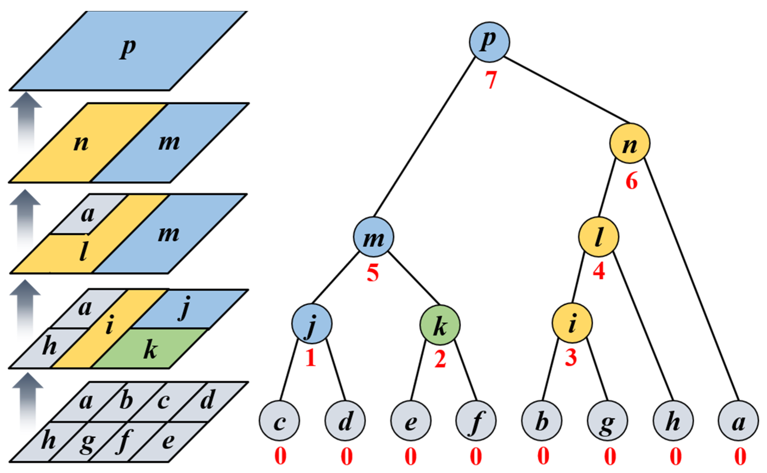
As shown in Figure 1, the BPT construction process is a bottom-up process in the merging sequence. Take the left 3-D image as an example; there are 8 pixels in the original image, which can be regarded as the leaf nodes. According to the distance proposed above, the two most similar neighboring nodes are merged into a new node through each iteration until the root node contains the whole pixels.
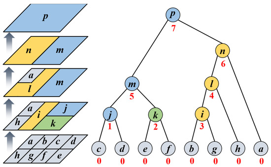
Figure 1.
The BPT construction diagrams. (left) The 3-D BPT construction process. (right) The hierarchical structure of BPT construction. The letters represent the indexes of the objects, the numbers represent the iteration numbers of each node, different colors represent different node objects.
The region model should be introduced to characterize the properties of the node, which is essential to the good representation of the tree. In this paper, the time-series covariance matrices and the multi-temporal optimum (OPT) complex coherence are used to construct the region model of each node, which satisfies the proper representation of the node and the calculation of the similarity distance. During each iteration, the region model has to be updated by averaging those of the last two nodes. With the continuous upward construction of the BPT, such updating process can well avoid the expansion of the computation.
2.2.2. Branch Pruning
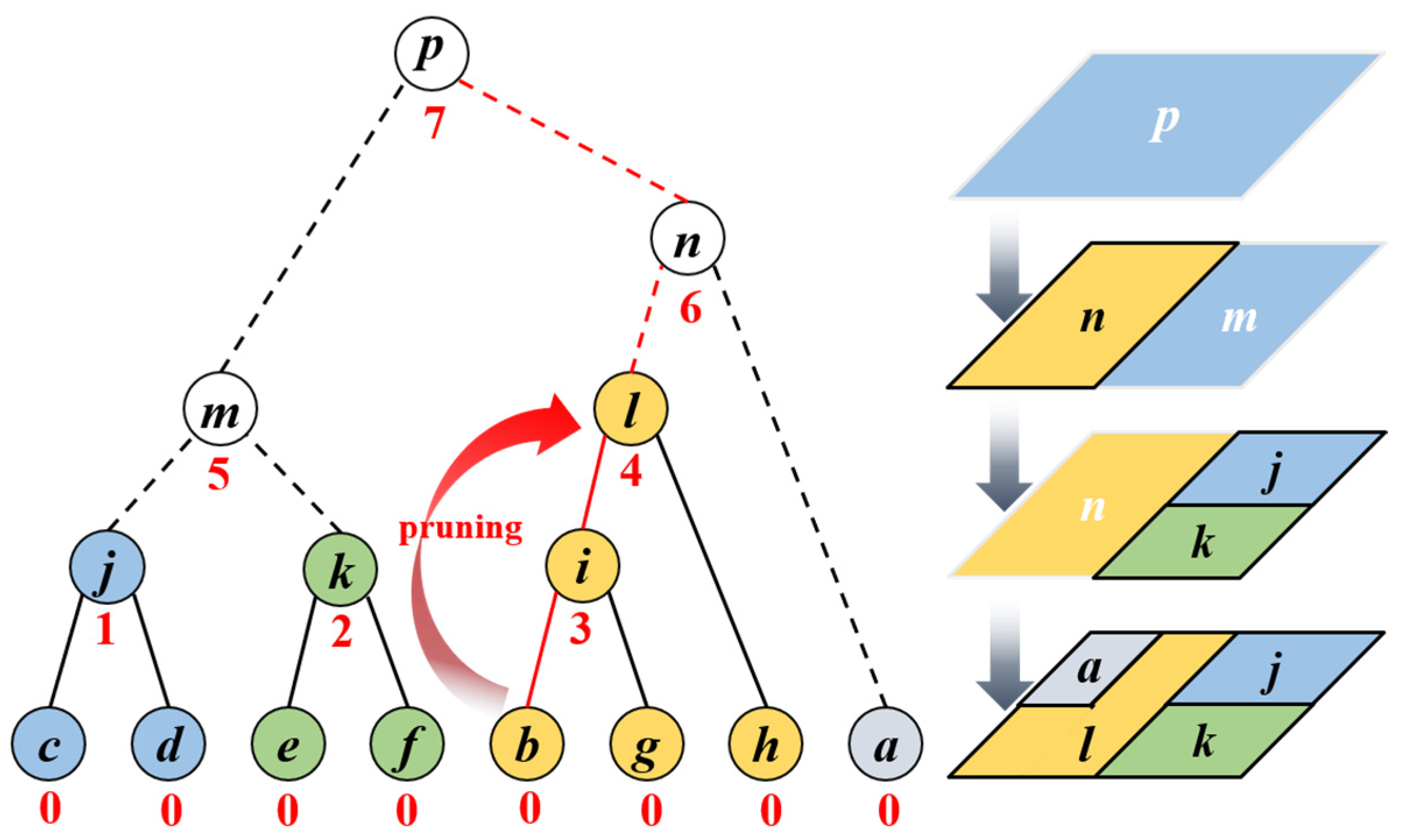
As the BPT is constructed, the whole image is transformed into a hierarchical tree. Such BPT has only one root node, namely the node p in the left Figure 1. Each node will have its corresponding number of iterations, as marked by the red number in the right Figure 2. However, the PIHP should be a multi-scale result obtained by the branch pruning process. Such a process is also a bottom-up process. It is necessary to set a pruning factor, which can be set empirically and varies with different test areas and data. The search for the pruning node starts from the leaf node. If the pruning factor is set to be , the nodes will be maintained when the iteration number , and the nodes will be pruned when .
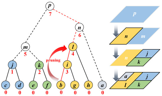
Figure 2.
The branch pruning diagrams with pruning factor . (left) The hierarchical structure of branch pruning. (right) the 3-D branch pruning process. The letters represent the indexes of the objects, and the numbers represent the iteration numbers of each node.
As shown in Figure 2, the pruned branches are indicated by dotted lines, and the remained branches are indicated by solid lines. The example marked by the red lines is explained in detail. Assuming that the method starts from leaf node and the pruning factor is 4, by searching upward along the red lines, the retained node is the last node with , and the rest nodes are considered as the pruning nodes, and the region will be one of the PIHPs in the final result. Similarly, the dotted lines in Figure 2 represent the pruning branches when the factor is 4. By pruning, the whole image is finally divided into a multi-scale PIHP map, as shown in the bottom right image in Figure 2.
2.3. Improved MT-InSAR Processing Strategy
It should be noted that the phase linking of the proposed MT-InSAR method is carried out under the criterion of multi-baseline equal scattering mechanism (ESM) [22,35] to ensure the phase triangulation [9] of the single-master interferometric phase. It means that the scatterers along all baselines are enforced as equal polarimetric signatures.
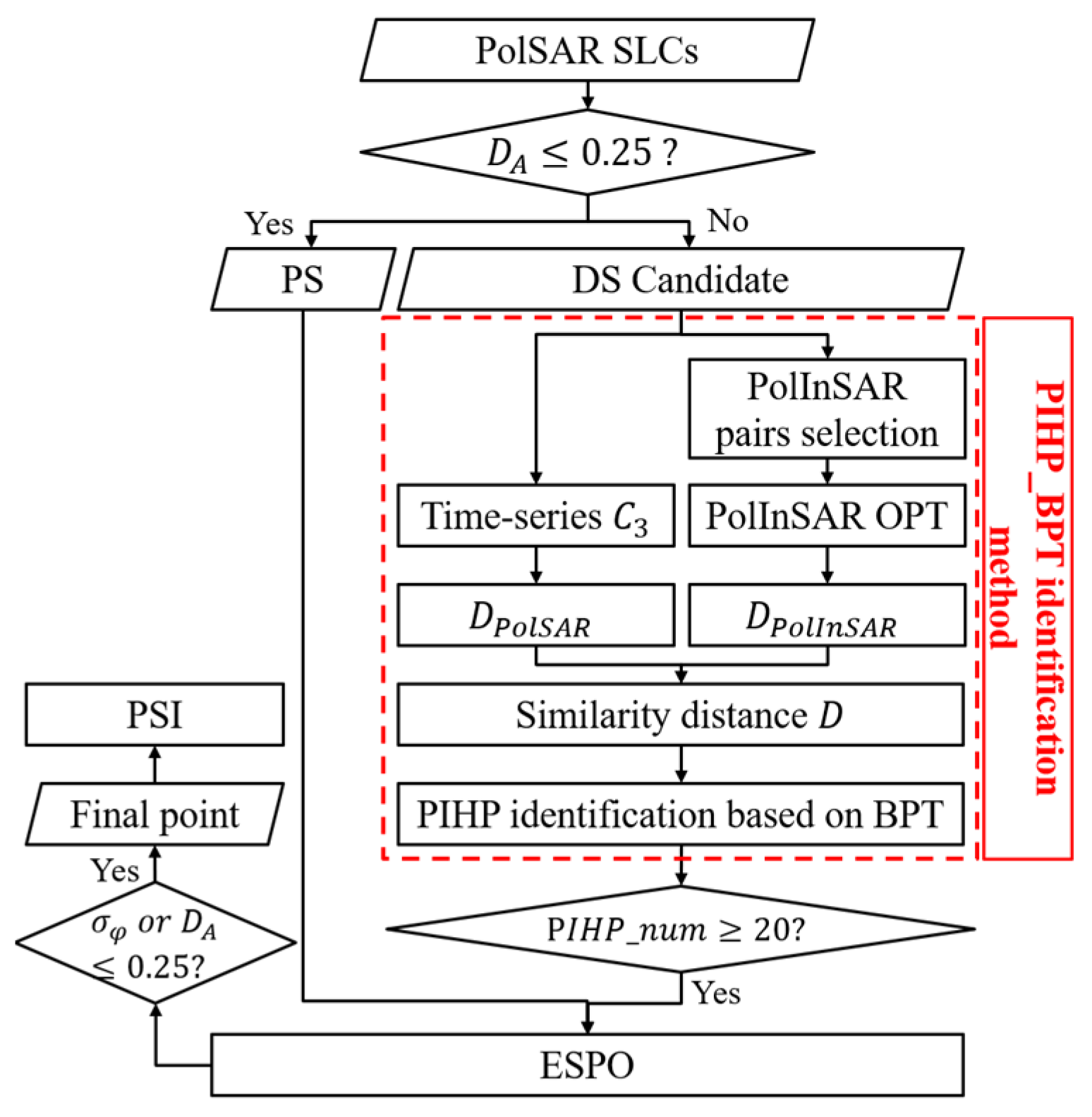
The improved MT-InSAR strategy uses the PSs and DSs jointly for deformation monitoring [10]. As shown in Figure 3, the novelty is marked with a red dashed box. Once the quad-polarization single-look complex (SLC) images are obtained, the corresponding intensity images of any polarization channel are used to calculate the amplitude dispersion for the separation of the PSs and DS candidates.
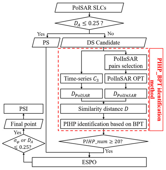
Figure 3.
Flowchart of the proposed MT-InSAR strategy.
As for the DS candidates, the PIHP identification method proposed in this paper is applied to obtain the PIHPs of each DS candidate. The PIHP of DS is usually considered to be over 20 pixels. By judging the PIHP number, the DS candidates are further selected.
The proposed method in this paper is not only useful for speckle noise reduction but also phase optimization. However, the multi-temporal interferometric phase of DS does not satisfy the phase triangulation, which needs to be reconstructed. Herein, the exhaustive search polarimetric optimization (ESPO) method is used for phase optimization [36]. Subsequently, the PS and DS points are examined by and respectively [22], and the qualified points participate in the conventional PSI.
3. Experimental Datasets
The novel method is tested with simulated datasets and real datasets. This section will specifically introduce the simulation process and parameters of simulated datasets, the experimental area covered by real datasets and its parameters.
3.1. Simulated Datasets Description and Parameter Settings
Five types of ground objects are designed in the pixels simulated image. As shown in Figure 4a, the data simulation mainly includes two steps. The first is to generate time-series PolSAR data, and the second is to simulate the multi-temporal PolInSAR data.

Figure 4.
(a) The ground object type map. (b) PauliRGB image of the 1st PolSAR image. (c) The original coherence map. (d) The simulated deformation phase of the first interferogram.
3.1.1. Time-Series PolSAR Data Generation
According to the complex Gaussian polarimetric model for most natural targets [37], the covariance matrix of each PolSAR image pixel can be formed as
where denotes the complex conjugate. is the intensity of HH, and is the intensity ratio as , is the intensity ratio as , and is a complex ratio as . As there are five kinds of ground objects in simulated area, refers to , corresponding to the object tags , respectively. The parameters and and the module of vary randomly between 0 and 1, and maintain the same values for each ground object. Based on such , the single-look quad-polarization SAR images are generated by using the Monte Carlo method with random noise, as shown in Figure 4b. It should be noted that the 10 PolSAR images are supposed to remain the same in time series, of which the revisit date keeps the same interval of 24 days.
3.1.2. Multi-Temporal PolInSAR Data Generation
Once the simulated is obtained, the PolInSAR matrix can be modeled as [38]
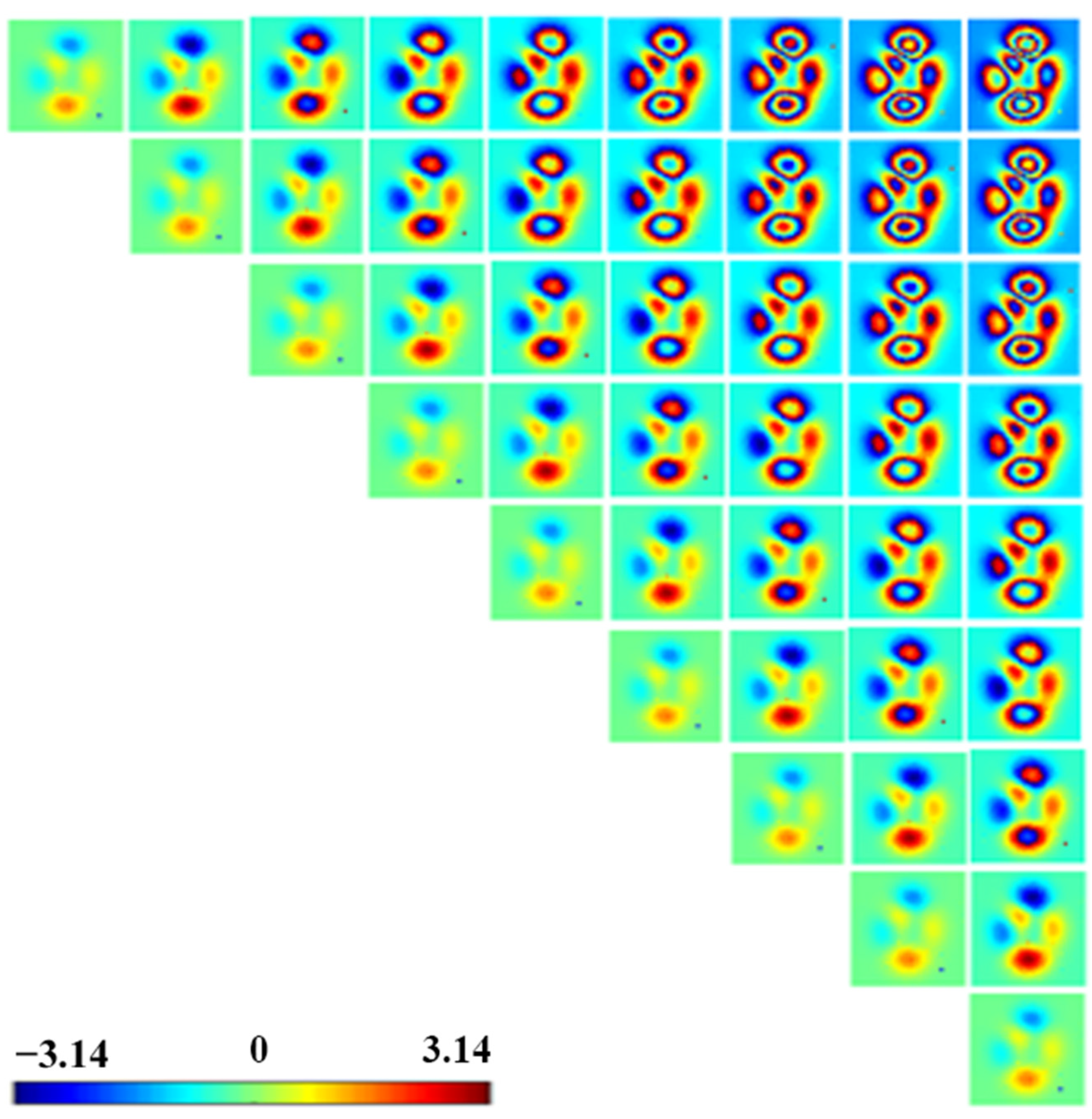
Additionally, the remaining simulation of PolInSAR data includes two parts: one is the simulation of the multi-temporal coherence correlation , and the other is the simulation of the wrapped deformation interferometric phase . The simulated consists of the original coherence and the multi-temporal coherence. As shown in Figure 4c, the original coherence map is generated corresponding to the objects distributed as Figure 4a. The multi-temporal coherence should meet different temporal baselines according to [39,40]. Herein, it is assumed that the spatial baselines are equal and the deformation develops linearly. As the interferometric phase with the shortest temporal baseline is designed as Figure 4d, the simulated 45 wrapped phase maps are shown in Figure 5.
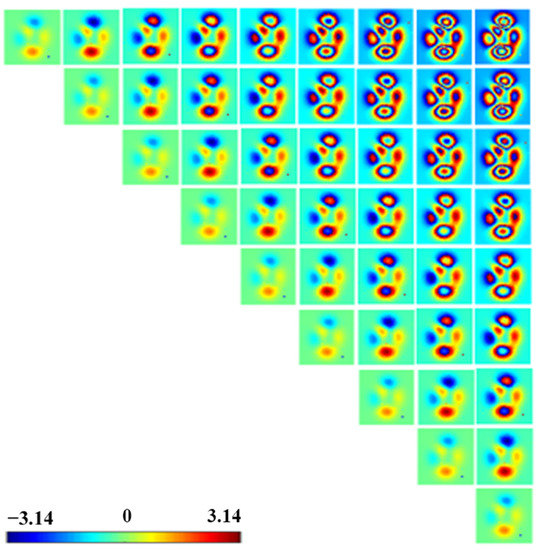
Figure 5.
The simulated multi-temporal wrapped deformation phase.
3.2. Real Datasets Description and Parameter Settings
To validate the performance of the proposed PIHP identification method on real data, a set of 30 quad-polarization C-band Radarsat-2 images was applied. The SLCs were acquired from 17 May 2011 to 14 November 2013 over Kilauea Volcano, Hawaii. The images were acquired by a revisit time of 24 days with the FQ20 mode. The resolution in nominal azimuth and slant range was 7.6 m and 5.2 m, corresponding to the pixel dimensions of 4.73 m and 4.84 m, respectively. The SLC contained pixels, covering an area of around .
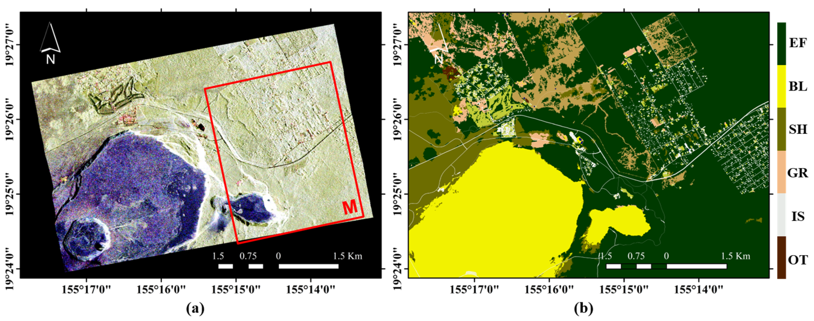
According to the landcover map published by National Oceanic and Atmospheric Administration (NOAA) in 2010 [41], there are mainly five kinds of ground objects in the test area, including the evergreen forest (EF), bare land (BL), grassland (GR), shrub (SH), and impervious surface (IS). The color composite formed by the Pauli average intensities is shown in Figure 6a, where various colors represent different scattering information of polarimetry.
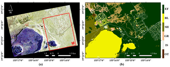
Figure 6.
(a) PauliRGB image of the study area in Kilauea Volcano (Hawaii) formed by the average intensities. (Channels: R = HH − VV, G = 2 × HV, B = HH + VV) (b) Landcover map from NOAA in 2010. (EF: evergreen forest; BL: bare land; SH: shrub; GR: grassland; IS: impervious surface; OT: others).
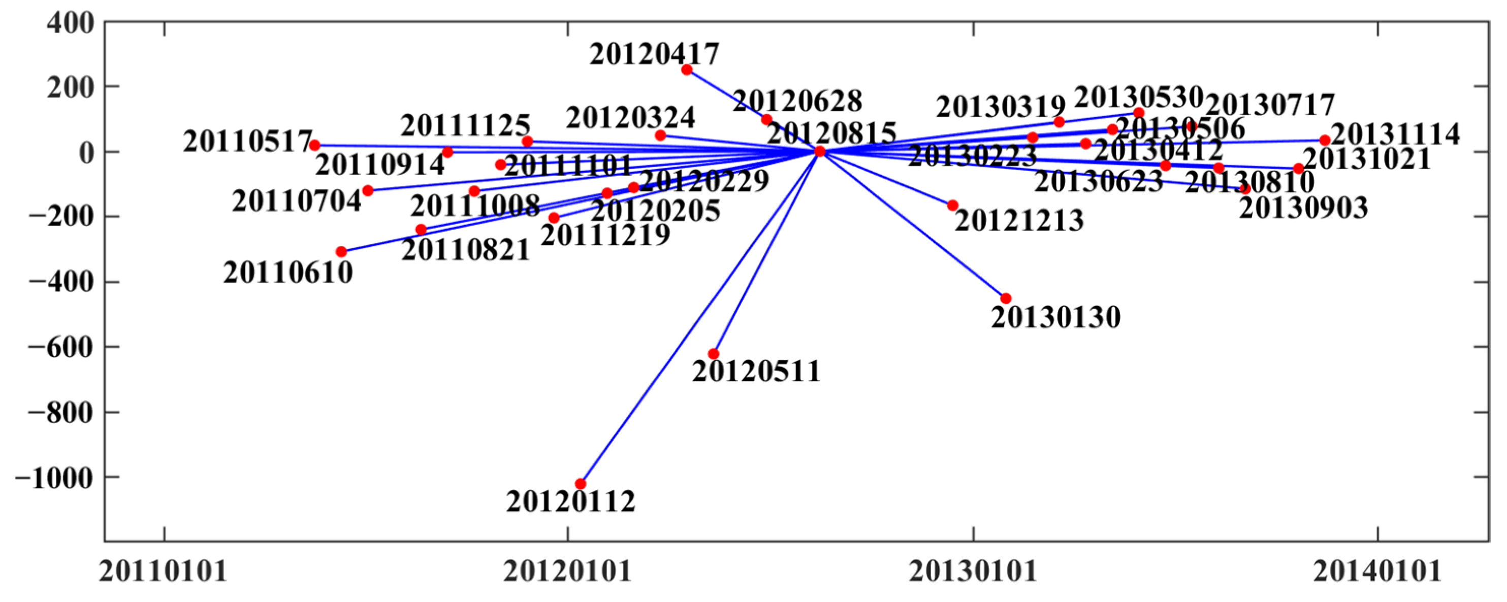
The MT-InSAR technology proposed in this paper uses the single-master network for interferometric pair composition, characterized by a radial network. The perpendicular and temporal baselines are shown in Figure 7. In view of the spatial-temporal baseline distribution of all images, we select the date “20120815” as the master image. It is evident that even if the small-baseline network is used for DS preprocessing, the spatial baselines of each interferometric pair are different.
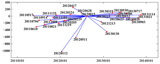
Figure 7.
Perpendicular and temporal baselines of single-master pairs (master image: 20120815) of real datasets.
4. Result and Discussion
The results of simulated datasets and real datasets are presented, respectively. Based on the simulated datasets, the proposed method is compared with the PolHom test and the ground object type map for comparison of the quantity and quality of the HPs. Based on the real datasets, the proposed method is compared with the PolHom test for comparison of the deformation results. In addition, the comparisons of different interferometric similarities and different polarimetric similarities are discussed in this section. Additionally, the performance of the proposed method with the dual-polarization data is discussed last.
4.1. Comparison of Different Methods
The results of simulated datasets and real datasets are compared with different methods. As for the simulated data experiments, the proposed PIHP method, the method with PolHom test [22], and the method with ground object type map are applied to discuss the results of homogeneous points selection and the effectiveness in the deformation region. As for the real data experiments, the deformation maps based on the proposed PIHP method and the PolHom test are obtained to verify the effects in the point selection of different ground objects over the Kilauea volcano.
4.1.1. Results of Simulated Datasets
In order to prove the necessity of interferometric information in PIHP identification, we compare the results obtained by only using the classification map and the proposed method. To verify the advantages of our method for selecting DS points in the deformation region, the traditional PolHom test is applied. It should be noted that the HP identification using a classification map is performed by using a fixed window to slide pixel by pixel to select the pixels owning the same classification as the center pixel of the window.
Considering that the coherence estimation is affected by the size of the spatial estimation window, the spatial identification scale of the above three methods should be consistent. It is common to define the parameter estimation window (PEW) as for PHP identification [22,42]. As the result of the PIHP identification method is multi-scale, the same PEW can be applied once the resulting map is obtained. Additionally, the fixed window of HP identification based on the classification map is the same as the PEW.
The number of DS points is taken as the quantitative evaluation criterion. The more DSs selected, the more effective input the method provides. As mentioned above, there are two empirical parameters affecting the PIHP method, namely the similarity distance weighting factor and the BPT pruning factor . The weighting factor determines the participation of interferometric information in PIHP identification. The larger the factor , the greater the contribution of the interferometric information to the similarity distance. The BPT pruning factor will affect the spatial scale of the final PIHP, which is a parameter empirically adjusted according to the test area and the test data. The larger the pruning factor , the smaller the spatial size of PIHP and the more fragmented the image is segmented.
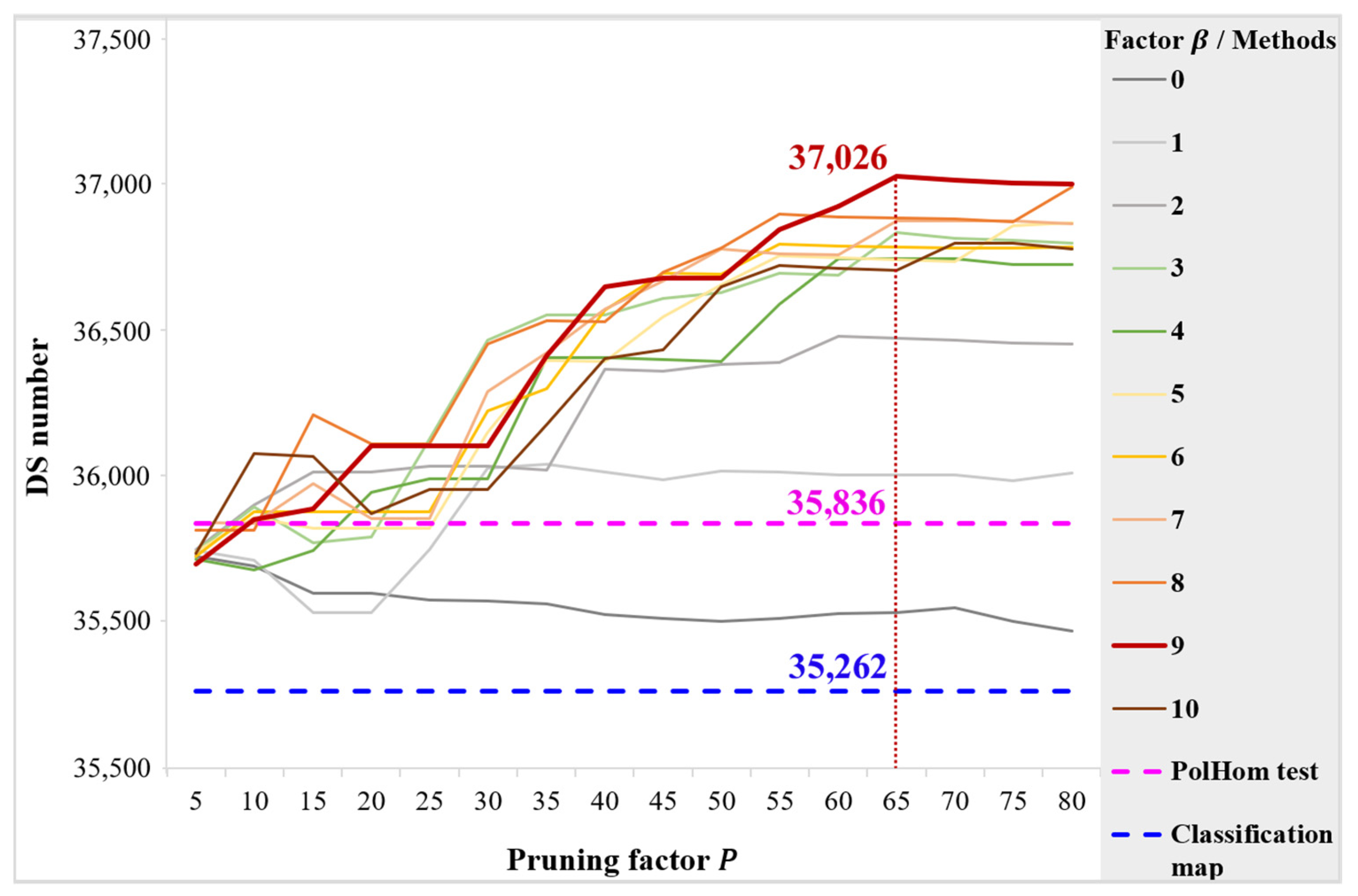
The multiple experiments are carried out under different pruning factors to illustrate the impact of the interferometric information on the PIHP identification. As shown in Figure 8, when , there is no interferometric information involved, and the effect of the PIHP identification is the worst. With the increase in weighting factor , the DS point number also improves. However, it is not linear growing progress. Obviously, when the weighting factor is 10, the result is not as ideal as the factor is 9. It is because the PIHP identification is a trade-off process between the polarimetry and the interferometry, namely the trade-off between the similarity and . If the weight of is too large, the contribution of will be darkened in similarity measurement, which is more sensitive to the speckle effect and can complement the .
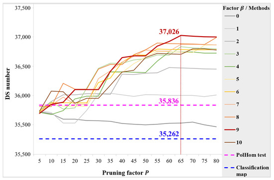
Figure 8.
The DS numbers under different pruning factors P by the classification map, the PolHom test, and the PIHP method with different weighting factors β.
In addition, considering that there are five kinds of ground objects designed in the simulated data, the pruning factor ranges from 5 to 80 at intervals of 5 to find the inflection point with the most DSs. It can be seen from Figure 8 that the DS number increases holistically with the increase in pruning factor increases when the interferometry is involved in similarity measurement. However, the too-small homogeneous region cannot meet the requirement of observation samples, leading to invalid phase reconstruction. The growing curves of the DS number are flat after , even appearing as downward trends.
In our method, the pruning factor has a greater impact on the results than the weighting factor , and the variation range is more flexible. Overall, the most DS points are obtained by , the sample of which is taken as the reference for comparisons with the other two methods. As shown in Figure 8, without the use of the interferometry, the DS number obtained by the PolHom test is limited, far less than that of the PIHP identification method when . Additionally, in the case of using the ground feature attributes only, the DS number obtained by the real classification map is the least among all methods. This is because neither the SAR data characteristics themselves nor the interferometric information is used in such a method.
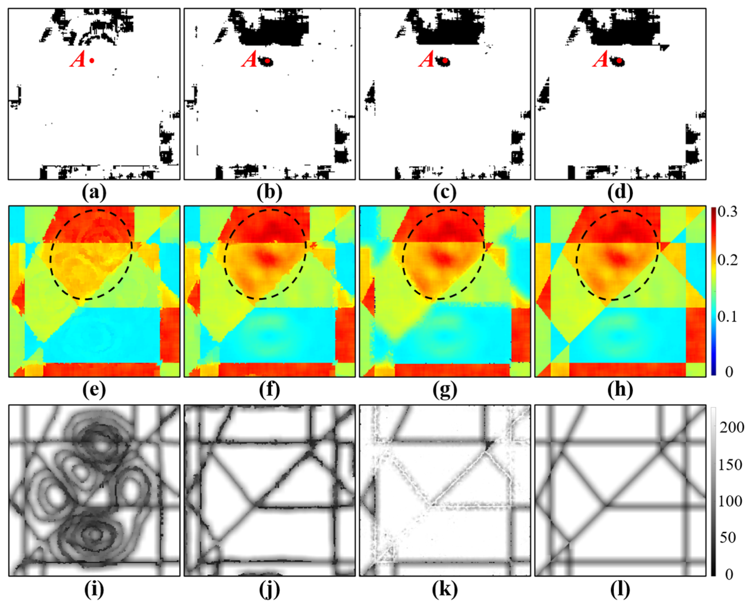
Intuitively, the final DS density of all methods in the low-coherence area is low, as shown in Figure 9a–d. However, compared with the other three methods, the PIHP method with obtains the most DS points by using the interferometry and polarimetry comprehensively. It should be noted that in the severely deformed area, DSs are hardly selected in other methods except our method. The DSs are selected by , which is a posterior index for phase quality evaluation. As seen in Figure 9e–h, the of our method is generally smaller than that of the other three methods, which means that the phase quality of our method is higher after ESPO. Especially in the area circled by the black dotted lines, only the of our method are not overestimated by the effects of deformation. It illustrates that our method avoids mistaking the deformation signal as an error. In addition, the comparisons of different methods in the pixel number of PIHP/PHP of each point are shown in Figure 9i–l. Obviously, the PIHP of our method expressed in Figure 9i applies the interferometry definitely, so the distribution of which has not only the polarimetric texture but also the interferometric texture. Moreover, it proves that not the more pixels in the PIHP/PHP, the better the phase quality.
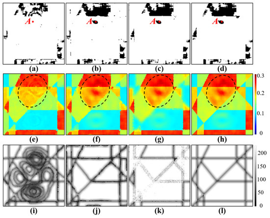
Figure 9.
The selected DSs by (a) PIHP method with P = 65, β = 9, (b) PIHP method with P = 65, β = 0, (c) PolHom test, (d) ground object type map. The phase quality σ_φ map by (e) PIHP method with P = 65, β = 9, (f) PIHP method with P = 65, β = 0, (g) PolHom test, (h) ground object type map. The number of homogeneous neighbors per pixel by (i) PIHP method with P = 65, β = 9, (j) PIHP method with P = 65, β = 0, (k) PolHom test, (l) ground object type map.
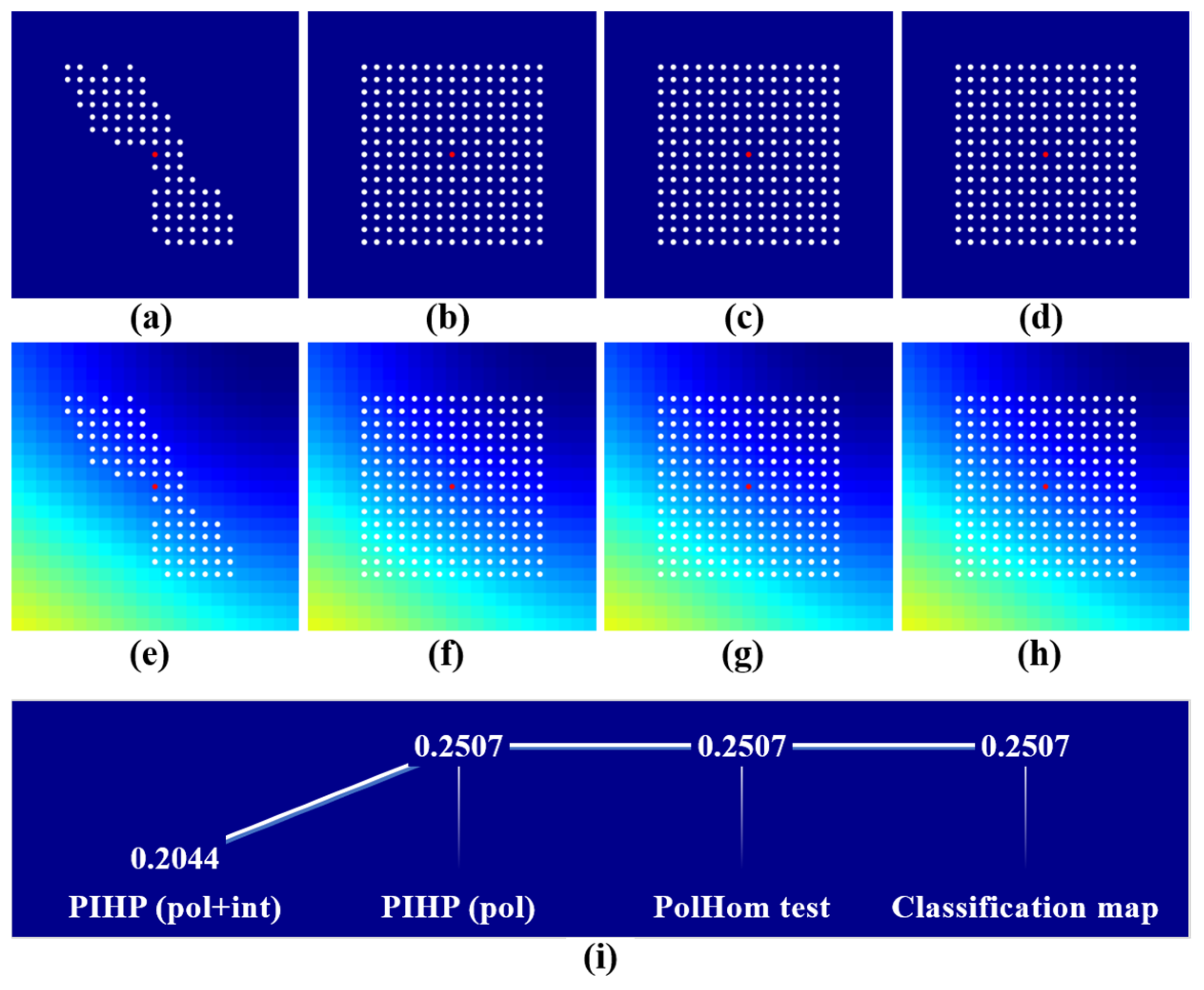
Figure 10 shows the homogeneous neighbors of pixel (58,99) with simulated interferogram base map and the corresponding . It can be seen that PIHP fits the interferometric phase distribution best and = 0.2044 of PIHP indicates the highest phase quality.
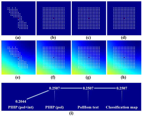
Figure 10.
The homogeneous neighbors of pixel (58,99) with simulated interferogram base map by (a) PIHP method with P = 65, β = 9, (b) PIHP method with P = 65, β = 0, (c) PolHom test, (d) ground object type map. The homogeneous points of pixel (58,99) with deformation base map by (e) PIHP method with P = 65, β = 9, (f) PIHP method with P = 65, β = 0, (g) PolHom test, (h) ground object type map. (i) The corresponding of each method.
To sum up, our method uses both the polarimetric and interferometric information in PIHP identification, and the parameters can be adjusted adaptively according to the test area and data. No matter how the parameters are set, the simulation experiments demonstrate the superiority of our method in the accurate identification of PIHP, which is conducive to phase reconstruction so as to improve the phase quality and point density. In particular, our method can effectively avoid the insufficient number of selected points in the deformed area.
4.1.2. Results of Real Datasets
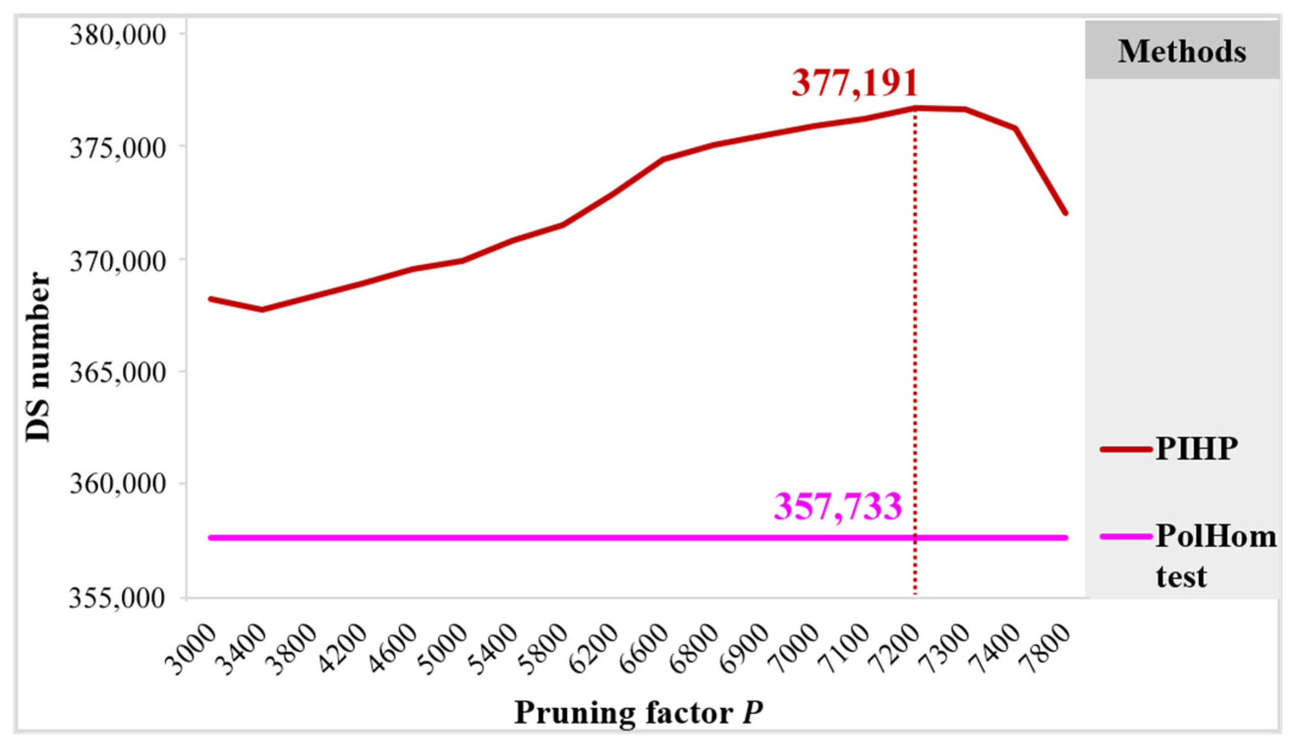
Based on the real datasets, the performance of the proposed method is evaluated by the point density and the detail of the generated deformation velocity maps. As for the DS point density, there are various real-data experiments carried out with the pruning factor . Compared with the pruning factor , the impact of the weighting factor is limited. Given the parameters of the best simulation results, the real-data experiments are all processed by . To validate the performance of our method, the PolHom test method is adopted for the comparisons. Firstly, the results of different methods are quantitatively evaluated by the final selected DS number. As shown in Figure 11, the DS number of our method is more than that of the PolHom test method, regardless of the pruning factor. As for our method, the DS number reaches the maximum of 377,191 when the pruning factor , which is higher than 357,733 points of the PolHom test method.
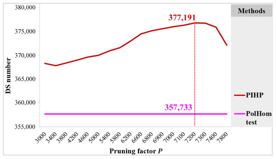
Figure 11.
The DS numbers under different pruning factors P by the PolHom test and the PIHP method when β = 9.
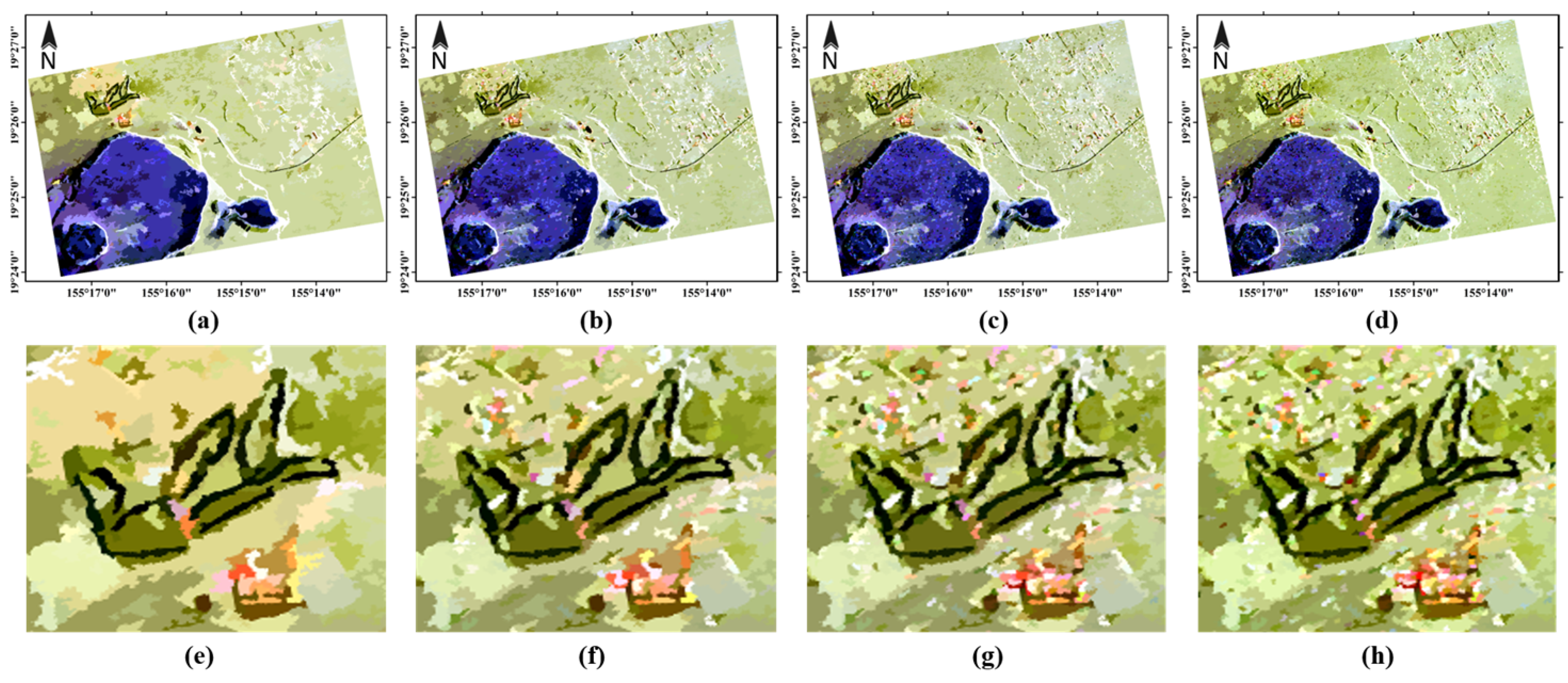
To intuitively display the impact of PIHP identification under different pruning factors, four additional experiments are completed corresponding to P = 1000, 3600, 7200, 10,000. As seen in Figure 12, the larger the pruning factor is, the finer the ground parcels are, and the more detailed the PIHP describes. Especially in Figure 12e–h, with the increase in , more ground objects are segmented in this area, which contains more details, but the small PIHP may be caused by the noise. It is worth noting that PIHP identification is a trade-off process, which needs to balance the fineness of the ground parcels and the similarity of pixels. If the PIHP is too small, the insufficient samples are unsatisfactory for phase filtering. If the PIHP is too large, the pixels are not homogeneous enough for phase reconstruction. According to Figure 11, the best result obtained when is taken as the reference for comparisons with the PolHom test method.
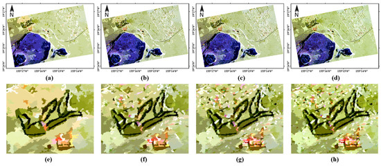
Figure 12.
The global and enlarged temporally averaged PauliRGB images with filtered C3 by PIHP method with the pruning factor (a,e): P = 1000; (b,f): P = 3600; (c,g): P = 7200; (d,h): P = 10,000.
In this experiment, the same parameters are considered for both the PIHP method and PolHom test method: the threshold for PS pre-selection and DS candidate determination, a predefined PIHP/PHP search window, the number threshold 20 pixels for DS pre-selection, the reconstructed phase quality and for DS and PS determination. Considering there are 30 images for PIHP identification, the window is set as for PolInSAR OPT calculation in our method.
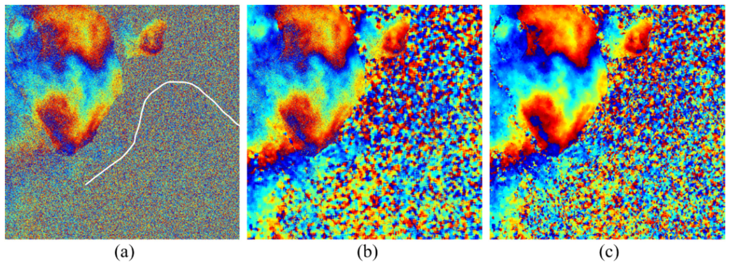
Figure 13 shows the interferograms of “20110517–20111101”. It can be seen that the interferogram based on PIHP is smoother than that based on PHP. In addition, Figure 13c shows that the scale of PIHP is large in areas with simple landcover types and small in areas with complex landcover types, which results in different filtering effects. According to Figure 6a, there is an east–west road in the study area, as indicated by the white lines in Figure 13a, which is obvious in the filtered interferogram with PIHP. While it cannot be found in Figure 13b due to the fixed identification window and incomplete similarity measure, it proves that the proposed method is more conducive to obtaining the accurate PIHP oriented to different ground objects compared with the PolHom test method.
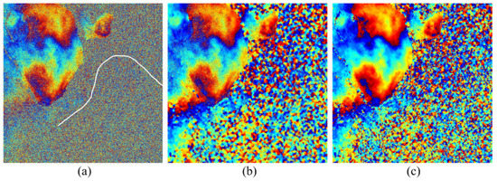
Figure 13.
The interferograms of “20110517–20111101”. (a) The original HH interferogram; (b) The filtered interferogram with PHP; (c) The filtered interferogram with PIHP.
In order to analyze the impacts of PIHP/PHP on coherence estimation, we make a quantitative analysis of the mean and standard deviation of coherence magnitude according to different ground objects. It can be seen from Table 1 that both two methods obtain unbiased estimation with a small standard deviation. The proposed method further provides a smaller standard deviation, especially in grassland and shrub areas. Although the mean coherence magnitude of our method is not as high as that of the PolHom test method in bare land, the value has exceeded 0.75, which fully satisfies the MT-InSAR monitoring. In addition, the mean values of our method have been improved in the other four ground objects, from large to small, followed by grassland, evergreen forest, impervious surface, and shrub. This shows that our method has advantages in increasing the deformation monitoring point density in vegetation areas.

Table 1.
Mean and standard deviation of the coherence magnitudes.
The deformation velocity maps have been generated for both methods using the traditional PSI algorithms described in [43]. In order to verify the advantages of our method, we also compared the results of SqueeSAR [9] with HH datasets. As shown in Figure 13, we can observe that there are some small differences in the deformation velocity results between different methods. It is because different point densities lead to a different network and different reliability of deformation results. Specifically, the higher the point density, the more stable the calculation network and the more reliable the deformation results. It can be seen that the proposed PIHP method has a significant improvement in point density, especially in the vegetated area, such as the evergreen forest and grassland or hay. In addition to the bare land and shrubs, the selected point density of our method in other areas (the right part of the image) is 8.06%, which is much higher than 1.72% of the PolHom test. However, note that the average number of homogeneous neighbors per pixel for our method (PIHPs) is smaller than that for the PolHom test method ( PHPs). It proves that the quality of phase optimization is not related to the size of PIHP/PHP but to the accuracy of the PIHP/PHP. Therefore, besides the polarimetry, our method uses interferometry to accurately describe the homogeneous region, which is helpful for phase optimization and effective for increasing the monitoring point density.
4.2. Comparison of Different Interferometric Similarities
The coherence optimization process is a crucial preprocessing step to ensure that the scattering mechanism is deterministic. In this paper, the first component of the coherent optimization results is used, which is the optimum result of the three-dimensional solution subspace. Additionally, the second component is the optimum result of the two-dimensional solution subspace, and the third component related to the smallest singular value is the result of the one-dimensional solution subspace [33]. Here, in addition to using the first component for interferometric distance calculation, the second and third components are also analyzed in this section.
Furthermore, another coherence optimization method proposed in [44] is implemented to investigate the sensitivity of the proposed method to the optimization method. Different from the coherent target decomposition proposed in [33], the method in [44] uses trace coherence to determine the center of mass of the coherence region. For ease of expression, we use the abbreviation OPT-1 for our method, OPT-2 for the second component, OPT-3 for the third component, and TraCoh for the method [44]. The comparison experiments of interferometric distances still use the datasets for polarimetric distance comparisons.
It can be found from the deformation maps that the increase in DS number in our method is mainly reflected in the eastern half of the study area. Therefore, a part of the test area is cut to compare the results of different polarimetric distances, as shown in the red box in Figure 6a. The size of the cut image is , covering around . The area is mainly distributed with evergreen forest, grassland, hay, pasture, and impervious surface.
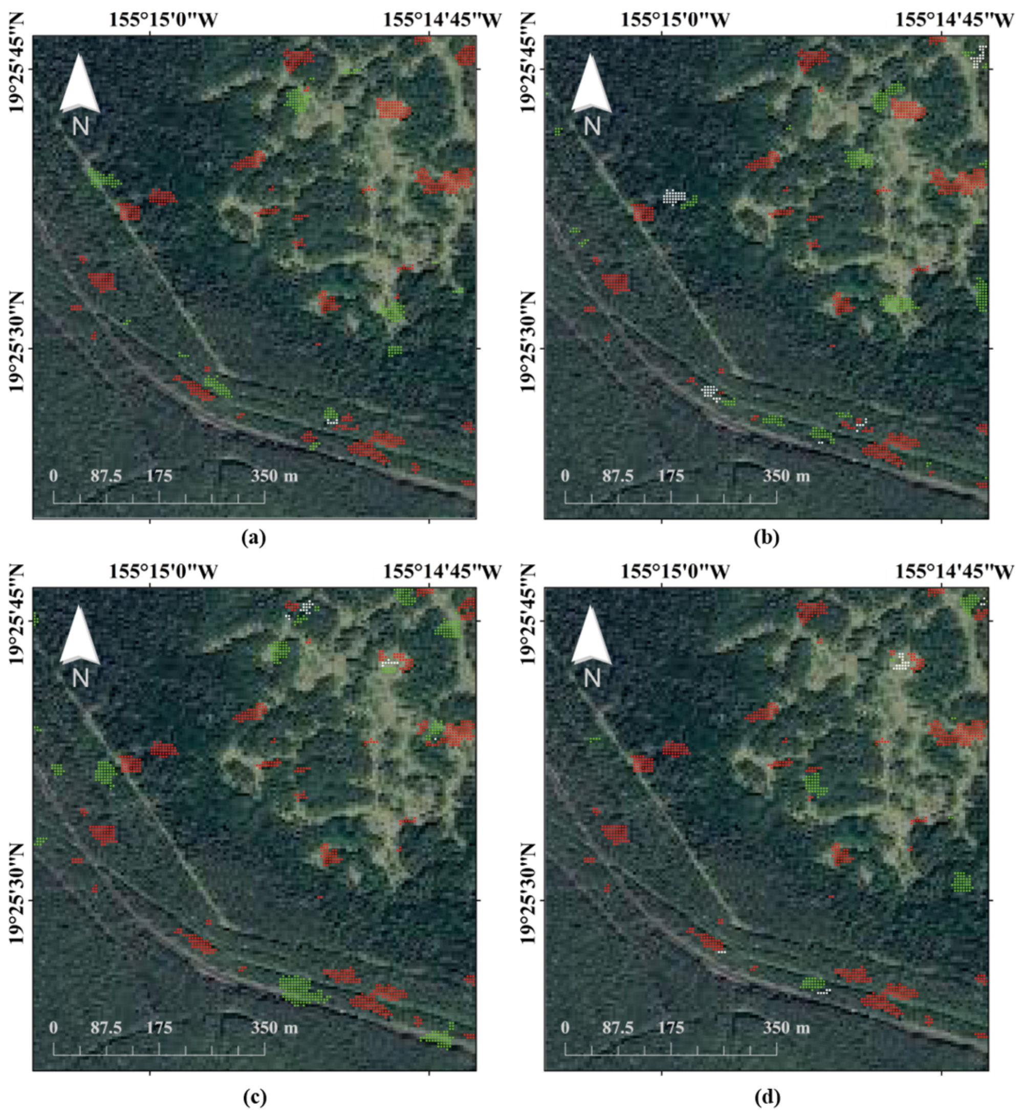
The DSs number of OPT-1, OPT-2, OPT-3, and TraCoh method is 28,613, 27,530, 21,894, and 27,725, respectively. In terms of the DSs quantity, there is no large difference in the DSs number. Hence, the local detail maps of selected DSs are enlarged in Figure 14. Among them, the red points represent the DSs selected by our method using the first component for interferometric distance, the green points represent the DSs selected by the other optimized interferometry and the white points represent the common DSs. Based on the optical base map, the area is mainly distributed with evergreen forests and grassland, which are usually the areas where the decorrelation noise is serious, and the InSAR deformation monitoring are very difficult. It can be seen from Figure 14 that the DSs distribution of our method is relatively even. The proposed method has obvious advantages over OPT-2 and OPT-3, but the advantages are weak over TraCoh.

Figure 14.
Deformation velocity maps obtained using (a) Single-pol method, (b) PolHom test method, and (c) PIHP method.
In addition, the applicability of our method to the dual-polarization data is verified. The proposed method is extended to VV-VH data, which is VV-VH in short. The DSs number is 23,330, 5283 less than the quad-polarization data. As shown in Figure 14, the results of quad-pol data are obviously superior to that of the dual-pol data. However, compared with the single-pol data, the use of multi-pol data has advantages for improving the DSs density.
4.3. Comparison of Different Polarimetric Similarities
There are many distance measures of matrix to describe the similarity of PolSAR data. The appropriate pairwise distance should meet four conditions: (1) generalized non-negativity, (2) identity of discernible, (3) symmetry, and (4) subadditivity. In general, the SRW distance satisfies the first three conditions, which is a robust measure between covariance matrices. It has been used widely in PolSAR classification and segmentation. To illustrate the advantages of SRW distances, the results of revised Wishart (RW) distances are compared. The RW distance can be regarded as the predecessor of the SRW distance. It is the maximum estimation derived from the generalized likelihood ratio test between two regional covariance matrices. The specific expression is
The relationship between the two polarimetric distances is . The equation seems simple, but the properties of these two distances are different. The SRW distance is the symmetric measure with respect to the RW distance, which is conducive to homogeneity evaluation.
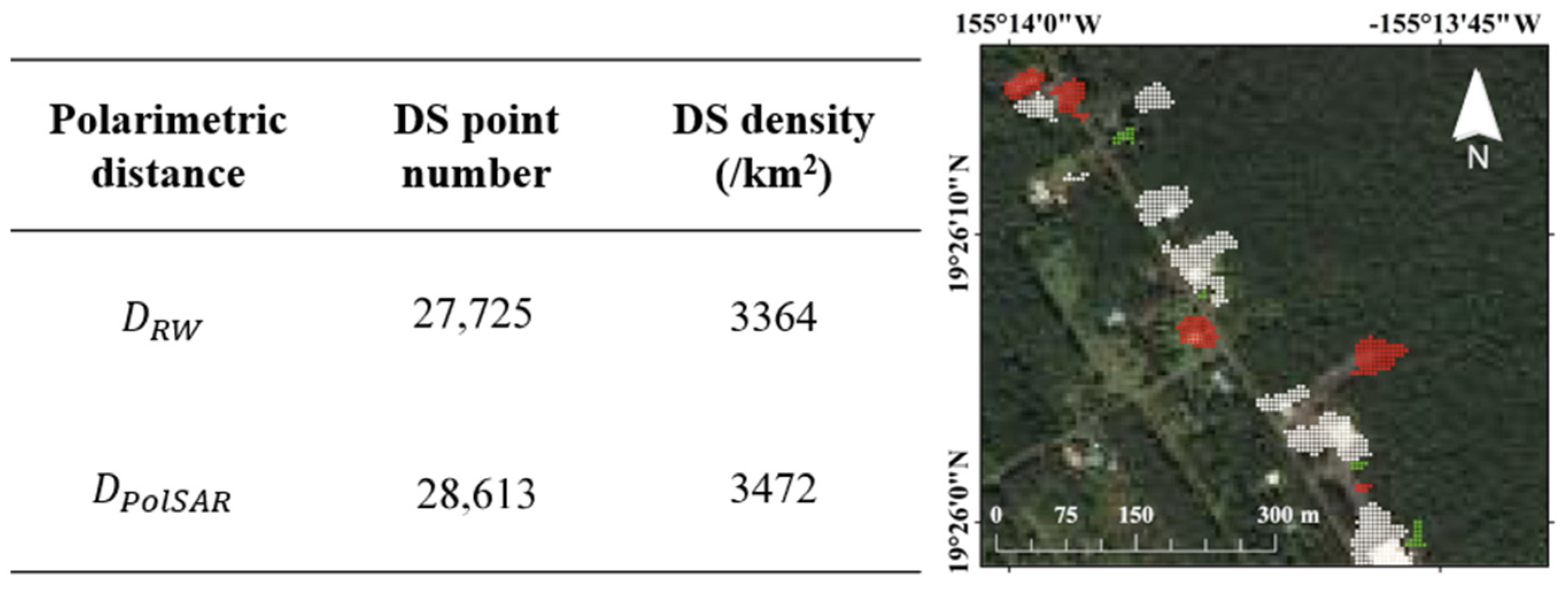
The comparison experiments of polarimetric distances still use the datasets for interferometric distance comparisons. As shown in Figure 15, the selected DS number of our method is 28,613, but the number of the RW distance method is 27,725, where the difference is small. For further explanation, the detailed map of DSs is shown in Figure 16. Among them, the white points are selected by both distances; the green points are selected by but not , the red points are selected by but not . Combined with the optical base map, it can be found that our method is superior to the method for DSs density of surrounding houses and grasslands along the diagonal road in the map.
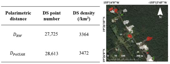
Figure 15.
The results of polarimetric distances and . The local detail map of DSs (red points: ; green points: ; white points: ).
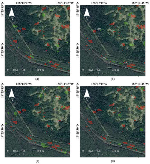
Figure 16.
The local detail map of DSs: (a) comparison between OPT-1 and OPT-2; (b) comparison between OPT-1 and OPT-3; (c) comparison between OPT-1 and TraCoh; (d) comparison between OPT-1 and VV-VH. The red points represent the DSs of OPT-1, the green points represent the DSs of the other method (OPT-2/OPT-3/TraCoh/VV-VH), and the white points represent the common DSs.
5. Conclusions
In this paper, we proposed a new homogeneous pixel identification method driven by the similarity of polarimetry and interferometry, which can effectively improve the monitoring point density in the deformed area and vegetation area. Additionally, the BPT framework is adopted for multi-scale PIHP identification, which makes the selected PIHP conform to the actual ground objects.
The proposed method was tested by using a set of quad-polarization simulated data and a set of quad-polarization Radarsat-2 data. As for the simulated-data experiment, the selected point density of our method is higher than that of the PolHom test method, especially in the deformed area. Additionally, the phase quality based on the PIHP is more accurate than that of the PHP, avoiding mistaking the deformation information as noise. As for the real-data experiment, the deformation results show a significant increase in point density in vegetation area, compared with the PolHom test method. The improvement of the phase quality and the increase of the point density will generally contribute to the robustness of MT-InSAR algorithms, which is helpful for high-accuracy monitoring results.
In this paper, a simple and effective PIHP identification method is provided, in which the interferometric similarity and the polarimetric similarity can be measured by a variety of methods. Based on the discussions, the utilized polarimetric and interferometric similarities are superior to traditional methods.
Author Contributions
Conceptualization and methodology, writing: G.W.; review and editing: K.D.; resources: Q.C.; project administration and funding acquisition: Z.L. and J.H.; visualization: H.G.; supervision: D.X. All authors have read and agreed to the published version of the manuscript.
Funding
This research was funded in part by the National Science Fund for Distinguished Young Scholars under Grant 41925016; in part by the Key Project of the National Natural Science Foundation of China under Grant 42030112; in part by Hunan Key Laboratory of remote sensing of ecological environment in Dongting Lake Area (No. 2021-010); in part by the Fundamental Research Funds for the Central Universities of Central South University (No. 2020zzts189).
Data Availability Statement
Not applicable.
Acknowledgments
The authors would like to thank the Canadian Space Agency (CSA) for providing Radarsat-2 data and the National Oceanic and Atmospheric Administration (NOAA) for providing the landcover map in 2010.
Conflicts of Interest
The authors declare no conflict of interest.
References
- Fatholahi, S.N.; He, H.; Wang, L.; Syed, A.; Li, J. Monitoring Surface Deformation Over Oilfield Using MT-Insar and Production Well Data. In Proceedings of the 2021 IEEE International Geoscience and Remote Sensing Symposium IGARSS, Brussels, Belgium, 11–16 July 2021; pp. 2298–2301. [Google Scholar]
- Luo, S.; Feng, G.; Xiong, Z.; Wang, H.; Zhao, Y.; Li, K.; Deng, K.; Wang, Y. An Improved Method for Automatic Identification and Assessment of Potential Geohazards Based on MT-InSAR Measurements. Remote Sens. 2021, 13, 3490. [Google Scholar] [CrossRef]
- Wu, S.; Zhang, B.; Liang, H.; Wang, C.; Ding, X.; Zhang, L. Detecting the Deformation Anomalies Induced by Underground Construction Using Multiplatform MT-InSAR: A Case Study in To Kwa Wan Station, Hong Kong. IEEE J. Sel. Top. Appl. Earth Obs. Remote Sens. 2021, 14, 9803–9814. [Google Scholar] [CrossRef]
- Wang, C.; Zhang, Z.; Zhang, H.; Zhang, B.; Tang, Y.; Wu, Q. Active Layer Thickness Retrieval of Qinghai–Tibet Permafrost Using the TerraSAR-X InSAR Technique. IEEE J. Sel. Top. Appl. Earth Obs. Remote Sens. 2018, 11, 4403–4413. [Google Scholar] [CrossRef]
- Ruiz-Armenteros, A.M.; Lazecky, M.; Hlaváčová, I.; Bakoň, M.; Delgado, J.M.; Sousa, J.J.; Lamas-Fernández, F.; Marchamalo, M.; Caro-Cuenca, M.; Papco, J.; et al. Deformation Monitoring of Dam Infrastructures via Spaceborne MT-InSAR. The Case of La Viñuela (Málaga, Southern Spain). Procedia Comput. Sci. 2018, 138, 346–353. [Google Scholar] [CrossRef]
- Zhu, B.; Chu, Z.; Shen, F.; Tang, W.; Wang, B.; Wang, X. Land Subsidence (2004–2013) in Changzhou in Central Yangtze River Delta Revealed by MT-InSAR. Nat. Hazards 2019, 97, 379–394. [Google Scholar] [CrossRef]
- Mahmud, M.U.; Yakubu, T.A.; Adewuyi, T.O.; Sousa, J.J.; Ruiz Armenteros, A.M.; Bakon, M.; Lazecky, M.; Perissin, D. Subsidence Monitoring in the Coastal Region of Nigeria Using Multi Temporal Interferometric Synthetic Aperture Radar (MT-Insar). In Proceedings of the Living Planet Symposium, Prague, Czech Republic, 9–13 May 2016. [Google Scholar]
- Hooper, A. A Multi-Temporal InSAR Method Incorporating Both Persistent Scatterer and Small Baseline Approaches. Geophys. Res. Lett. 2008, 35, L16302. [Google Scholar] [CrossRef]
- Ferretti, A.; Fumagalli, A.; Novali, F.; Prati, C.; Rocca, F.; Rucci, A. A New Algorithm for Processing Interferometric Data-Stacks: SqueeSAR. IEEE Trans. Geosci. Remote Sens. 2011, 49, 3460–3470. [Google Scholar] [CrossRef]
- Even, M.; Schulz, K. InSAR Deformation Analysis with Distributed Scatterers: A Review Complemented by New Advances. Remote Sens. 2018, 10, 744. [Google Scholar] [CrossRef]
- Sun, Q.; Jiang, L.; Jiang, M.; Lin, H.; Ma, P.; Wang, H. Monitoring Coastal Reclamation Subsidence in Hong Kong with Distributed Scatterer Interferometry. Remote Sens. 2018, 10, 1738. [Google Scholar] [CrossRef]
- Liu, Y.; Fan, H.; Wang, L.; Zhuang, H. Monitoring of Surface Deformation in a Low Coherence Area Using Distributed Scatterers InSAR: Case Study in the Xiaolangdi Basin of the Yellow River, China. Bull. Eng. Geol. Environ. 2021, 80, 25–39. [Google Scholar] [CrossRef]
- Du, Y.; Yan, S.; Yang, H.; Jiang, J.; Zhao, F. Investigation of Deformation Patterns by DS-InSAR in a Coal Resource-Exhausted Region with Spaceborne SAR Imagery. J. Asian Earth Sci. X 2021, 5, 100049. [Google Scholar] [CrossRef]
- Wang, G.; Xu, B.; Li, Z.; Fu, H.; Gao, H.; Wan, J.; Wang, C. A Phase Optimization Method for DS-InSAR Based on SKP Decomposition From Quad-Polarized Data. IEEE Geosci. Remote Sens. Lett. 2022, 19, 1–5. [Google Scholar] [CrossRef]
- Bao, J.; Luo, X.; Liu, G.; Chang, L.; Wang, X.; Shi, Y.; Wu, S. An Improved Distributed Scatterers Extraction Algorithm for Monitoring Tattered Ground Surface Subsidence with DSInSAR: A Case Study of Loess Landform in Tongren County. Int. J. Appl. Earth Obs. Geoinf. 2021, 99, 102322. [Google Scholar] [CrossRef]
- Narayan, A.B.; Tiwari, A.; Dwivedi, R.; Dikshit, O. A Novel Measure for Categorization and Optimal Phase History Retrieval of Distributed Scatterers for InSAR Applications. IEEE Trans. Geosci. Remote Sens. 2018, 56, 5843–5849. [Google Scholar] [CrossRef]
- Jiang, M.; Ding, X.; Hanssen, R.F.; Malhotra, R.; Chang, L. Fast Statistically Homogeneous Pixel Selection for Covariance Matrix Estimation for Multitemporal InSAR. IEEE Trans. Geosci. Remote Sens. 2015, 53, 1213–1224. [Google Scholar] [CrossRef]
- Wang, Y.; Zhu, X.X.; Bamler, R. Optimal Estimation of Distributed Scatterer Phase History Parameters from Meter-Resolution SAR Data. In Proceedings of the 2011 IEEE International Geoscience and Remote Sensing Symposium, Vancouver, BC, Canada, 24–29 July 2011; pp. 3468–3471. [Google Scholar]
- Goel, K.; Adam, N. A Distributed Scatterer Interferometry Approach for Precision Monitoring of Known Surface Deformation Phenomena. IEEE Trans. Geosci. Remote Sens. 2014, 52, 5454–5468. [Google Scholar] [CrossRef]
- Parizzi, A.; Brcic, R. Adaptive InSAR Stack Multilooking Exploiting Amplitude Statistics: A Comparison Between Different Techniques and Practical Results. IEEE Geosci. Remote Sens. Lett. 2011, 8, 441–445. [Google Scholar] [CrossRef]
- Lee, J.; Pottier, E. Polarimetric Radar Imaging: From Basics to Applications; CRC Press: Boca Raton, FL, USA, 2017; ISBN 978-1-315-21933-2. [Google Scholar]
- Navarro-Sanchez, V.D.; Lopez-Sanchez, J.M. Spatial Adaptive Speckle Filtering Driven by Temporal Polarimetric Statistics and Its Application to PSI. IEEE Trans. Geosci. Remote Sens. 2014, 52, 4548–4557. [Google Scholar] [CrossRef]
- Mullissa, A.G.; Perissin, D.; Tolpekin, V.A.; Stein, A. Polarimetry-Based Distributed Scatterer Processing Method for PSI Applications. IEEE Trans. Geosci. Remote Sens. 2018, 56, 3371–3382. [Google Scholar] [CrossRef]
- Dong, J.; Liao, M.; Zhang, L.; Gong, J. A Unified Approach of Multitemporal SAR Data Filtering Through Adaptive Estimation of Complex Covariance Matrix. IEEE Trans. Geosci. Remote Sens. 2018, 56, 5320–5333. [Google Scholar] [CrossRef]
- Alonso-González, A.; López-Martínez, C.; Salembier, P. PolSAR Time Series Processing With Binary Partition Trees. IEEE Trans. Geosci. Remote Sens. 2014, 52, 3553–3567. [Google Scholar] [CrossRef]
- Chen, S.-W.; Wang, X.-S.; Sato, M. PolInSAR Complex Coherence Estimation Based on Covariance Matrix Similarity Test. IEEE Trans. Geosci. Remote Sens. 2012, 50, 4699–4710. [Google Scholar] [CrossRef]
- Xiang, D.; Ban, Y.; Wang, W.; Su, Y. Adaptive Superpixel Generation for Polarimetric SAR Images With Local Iterative Clustering and SIRV Model. IEEE Trans. Geosci. Remote Sens. 2017, 55, 3115–3131. [Google Scholar] [CrossRef]
- Salembier, P.; Garrido, L. Binary Partition Tree as an Efficient Representation for Image Processing, Segmentation, and Information Retrieval. IEEE Trans. Image Process. 2000, 9, 561–576. [Google Scholar] [CrossRef] [PubMed]
- Beaulieu, J.-M.; Touzi, R. Segmentation of Textured Polarimetric SAR Scenes by Likelihood Approximation. IEEE Trans. Geosci. Remote Sens. 2004, 42, 2063–2072. [Google Scholar] [CrossRef]
- Li, M.; Stein, A.; Bijker, W.; Zhan, Q. Region-Based Urban Road Extraction from VHR Satellite Images Using Binary Partition Tree. Int. J. Appl. Earth Obs. Geoinf. 2016, 44, 217–225. [Google Scholar] [CrossRef]
- Anfinsen, S.N.; Jenssen, R.; Eltoft, T. Spectral Clustering of Polarimetric SAR Data with the Wishart-Derived Distance Measures. In Proceedings of the 3rd International Workshop on Science and Applications of SAR Polarimetry and Polari-metric Interferometry, Frascati, Italy, 22–26 January 2007; Volume 644, p. 10. [Google Scholar]
- Gao, H.; Wang, C.; Xiang, D.; Ye, J.; Wang, G. TSPol-ASLIC: Adaptive Superpixel Generation With Local Iterative Clustering for Time-Series Quad- and Dual-Polarization SAR Data. IEEE Trans. Geosci. Remote Sens. 2022, 60, 1–15. [Google Scholar] [CrossRef]
- Cloude, S.R.; Papathanassiou, K.P. Polarimetric SAR Interferometry. IEEE Trans. Geosci. Remote Sens. 1998, 36, 1551–1565. [Google Scholar] [CrossRef]
- Xing, C.; Zhang, T.; Wang, H.; Zeng, L.; Yin, J.; Yang, J. A Novel Four-Stage Method for Vegetation Height Estimation with Repeat-Pass PolInSAR Data via Temporal Decorrelation Adaptive Estimation and Distance Transformation. Remote Sens. 2021, 13, 213. [Google Scholar] [CrossRef]
- Neumann, M.; Ferro-Famil, L.; Reigber, A. Multibaseline Polarimetric SAR Interferometry Coherence Optimization. IEEE Geosci. Remote Sens. Lett. 2008, 5, 93–97. [Google Scholar] [CrossRef]
- Navarro-Sanchez, V.D.; Lopez-Sanchez, J.M.; Vicente-Guijalba, F. A Contribution of Polarimetry to Satellite Differential SAR Interferometry: Increasing the Number of Pixel Candidates. IEEE Geosci. Remote Sens. Lett. 2010, 7, 276–280. [Google Scholar] [CrossRef]
- Novak, L.M.; Burl, M.C. Optimal Speckle Reduction In Polarimetric Sar Imagery. In Proceedings of the Twenty-Second Asilomar Conference on Signals, Systems and Computers, Pacific Grove, CA, USA, 31 October–2 November 1988; Volume 2, pp. 781–793. [Google Scholar]
- Shen, P.; Wang, C.; Hu, J.; Fu, H.; Zhu, J. Interferometric Phase Optimization Based on PolInSAR Total Power Coherency Matrix Construction and Joint Polarization-Space Nonlocal Estimation. IEEE Trans. Geosci. Remote Sens. 2022, 60, 1–14. [Google Scholar] [CrossRef]
- Shen, P.; Wang, C.; Fu, H.; Zhu, J.; Hu, J. Estimation of Equivalent Number of Looks in Time-Series Pol(In)SAR Data. Remote Sens. 2020, 12, 2715. [Google Scholar] [CrossRef]
- Sica, F.; Pulella, A.; Nannini, M.; Pinheiro, M.; Rizzoli, P. Repeat-Pass SAR Interferometry for Land Cover Classification: A Methodology Using Sentinel-1 Short-Time-Series. Remote Sens. Environ. 2019, 232, 111277. [Google Scholar] [CrossRef]
- Homer, C.; Dewitz, J.; Yang, L.; Jin, S.; Danielson, P.; Xian, G.; Coulston, J.; Herold, N.; Wickham, J.; Megown, K. Completion of the 2011 National Land Cover Database for the Conterminous United States—Representing a Decade of Land Cover Change Information. Photogramm. Eng. Remote Sens. 2015, 81, 346–354. [Google Scholar] [CrossRef]
- Mi, J.; Xiao-Li, D.; Xiu-Feng, H.E.; Zhi-Wei, L.I.; Guo-Qiang, S.H.I. FaSHPS-InSAR technique for distributed scatterers: A case study over the lost hills oil field, California. Chin. J. Geophys. 2016, 59, 3592–3603. [Google Scholar] [CrossRef]
- Ferretti, A.; Prati, C.; Rocca, F. Nonlinear Subsidence Rate Estimation Using Permanent Scatterers in Differential SAR Interferometry. IEEE Trans. Geosci. Remote Sens. 2000, 38, 2202–2212. [Google Scholar] [CrossRef]
- Marino, A. Trace Coherence: A New Operator for Polarimetric and Interferometric SAR Images. IEEE Trans. Geosci. Remote Sens. 2017, 55, 2326–2339. [Google Scholar] [CrossRef]
Publisher’s Note: MDPI stays neutral with regard to jurisdictional claims in published maps and institutional affiliations. |
© 2022 by the authors. Licensee MDPI, Basel, Switzerland. This article is an open access article distributed under the terms and conditions of the Creative Commons Attribution (CC BY) license (https://creativecommons.org/licenses/by/4.0/).

