Technical Note

Suppression of Jammer Multipath in GNSS Antenna Array Receiver

1
College of Electronic Science and Technology, National University of Defense Technology, Changsha 410073, China
2
Beijing BDStar Navigation Co., Ltd., Beijing 100080, China
*
Author to whom correspondence should be addressed.
Remote Sens. 2022, 14(2), 350; https://doi.org/10.3390/rs14020350
Submission received: 9 December 2021 / Revised: 9 January 2022 / Accepted: 10 January 2022 / Published: 13 January 2022

Abstract

:
Interference multipath is an important factor to affect the anti-jamming performance for the global navigation satellite system (GNSS) antenna array receiver. However, interference multipath must be considered in practical application. In this paper, the antenna array model for interference multipath is analyzed, and an equivalent model for interference multipath is proposed. According to the equivalent interference multipath model, the influence of interference multipath on anti-jamming performance is analyzed from the space only processing (SOP) and space-time adaptive processing (STAP). Interference multipath can cause loss of the degree of freedom (DoF) of SOP. Through analysis of the equivalent model and STAP mechanism, it further reveals how the STAP can solve the interference multipath. The simulation experiments prove that the equivalent model is effective, and the analysis conclusion is correct. This paper also points out that the interference bandwidth is wider and more taps in STAP are required, under the same experiment conditions.

Graphical Abstract

1. Introduction

Global navigation satellite system (GNSS), represented by global position system (GPS), is a space-based navigation and positioning system, which is widely used in various fields such as land, sea and air navigation, aerospace, geodesy, and other national defense construction and national economy with its full space coverage, all-weather work, and high positioning accuracy [1,2,3]. When the navigation signal arrives at the ground, the signal is already very weak, so it is susceptible to various intentional or unintentional interferences [4,5,6]. For military or core civilian areas, anti-jamming performance is an important indicator to evaluate the navigation receivers [7,8]. The interference cancellation technology with antenna array is a common technology for a user terminal because it not only can suppress narrowband interference, but can also suppress wideband interference [9,10,11,12]. The navigation in the transmission process would encounter dense forests or urban canyons, but the interference transmission would encounter the same situation [13]. Hence, not only the signal would be affected by the multipath, but also the multipath would impact the interference transmission [14,15]. In this paper, the signal multipath guides the multipath effect for navigation signal, and the interference multipath refers to the multipath for interference. In the environment of navigation confrontation, the interference power is much greater than the signal and noise power, so the effect of interference multipath may be greater than the influence of signal multipath on antenna array navigation receiver. According to our test experience, for the GNSS antenna array anti-jamming receiver, regardless of the signal quality except for the degree of interference suppression, the test results in the darkroom are often better than the field test results; one of the important reasons is that the multipath effect exists in the field test.
Multipath effects have attracted much attention in navigation signal processing. The signal multipath not only causes the distortion of the pseudo-random code, but also causes the distortion of the carrier and code phase. In turn, it affects the measurement accuracy of the navigation receiver and ultimately affects the positioning and timing accuracy. The phenomenon for interference multipath has also been studied, preliminarily. The radar system appears earlier than the navigation system, so some innovations in the radar system can be used for a navigation system. In literature [16], the influence of interference multipath on the airborne adaptive radar system is analyzed. This literature points out that the interference multipath will affect the signal to interference plus the noise ratio (SINR) of the array output, and it also indicates that the effect of interference multipath could be suppressed by space-time adaptive processing (STAP). In the field of navigation, the literature [17,18] demonstrated by simulation that jammers and jammer multipath can be cancelled using an adaptive space-time array, leading to nearly ideal GPS performance. The current research results show that STAP can suppress the interference multipath, but this research still remains on the basis of simulation and experiment and has not pointed out the reason and essence.
In this paper, according to the array and jammer multipath model, the equivalent model for jammer multipath is given. After that, we analyze the impact of jammer multipath on anti-jamming performance based on space only processing (SOP) and STAP. The remainder of this paper is organized as follows. Section 2 gives the mathematic models for the antenna array and jammer multipath. Section 3 analyzes the impact of multipath on anti-jamming performance. Section 4 demonstrates that the simulation experiment results show the effectiveness of the proposed analysis and method to suppress the jammer multipath. A brief conclusion is presented in the last section.

2. Mathematics Model

2.1. Array Model

The antenna array is composed of multiple antenna array elements. Each array element uses an independent radio frequency channel. Different array elements cannot interfere with each other. Sampling data for fusion processing. The four-element antenna array is a commonly used antenna array in the author’s team. The four element square array picture and model are shown in Figure 1 [19,20].
where θ and φ are the pitch and azimuth of jammer or signal; τ ( θ ) is the time delay difference that the jammer or signal reaches to the array center for different elements. If the reference point is in the array center, the delay time for the four elements can be denoted as [21]:
τ A 1 = 2 d 2 c cos θ cos φ
τ A 2 = 2 d 2 c cos θ sin φ
τ A 3 = 2 d 2 c cos θ cos φ
τ A 4 = 2 d 2 c cos θ sin φ
where d is the distance for adjacent antennas, which is the wavelength half of the signal, and c is the speed of jammer and signal propagation.
The steering vector can be expressed as:
a ( θ , φ ) = e j ω [ τ A 1 τ A 2 τ A 3 τ A 4 ]
Therefore, the array data can be denoted as:
x ( t ) = k = 1 K a ( θ j k , φ j k ) j k ( t ) + l = 1 L a ( θ s l , φ s l ) s l ( t ) + n ( t )
where K and L are the numbers of interference and signal, respectively. j k ( t ) and s l ( t ) are interference k and signal l in the reference element on the time domain expression. ( θ j k , φ j k ) and ( θ s l , φ s l ) are the direction for interference k and signal l. n ( t ) is the noise vector with 4 × 1 .
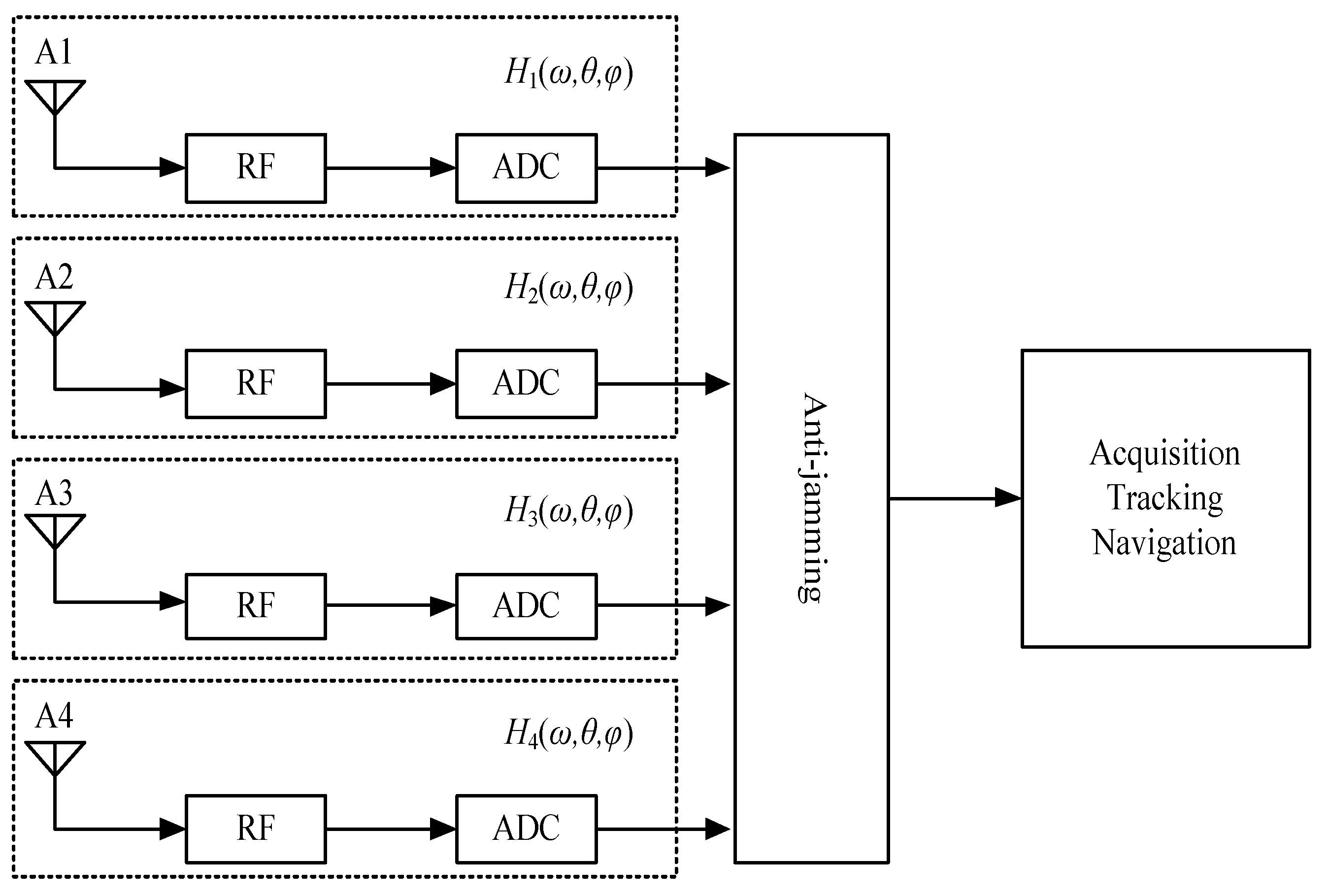
The navigation receivers based on antenna array include not only antennas but also radio frequency (RF) channels, ADCs, the digital signal processer, and so on. Anti-jamming processing and navigation signal processing are all implemented in digital signal processors. Figure 2 shows the antenna array structure [22].
In the above structure, H i ( ω , θ , φ ) is the transfer function, including the whole analog circuit and the ADC. At the same time, the direction of interference and signal is also in H i ( ω , θ , φ ) . Anti-jamming processing is in the digital signal processor. In addition, the acquisition, tracking, and navigation, which process after anti-jamming, are also in the digital signal processor.

2.2. Jammer Multipath Model

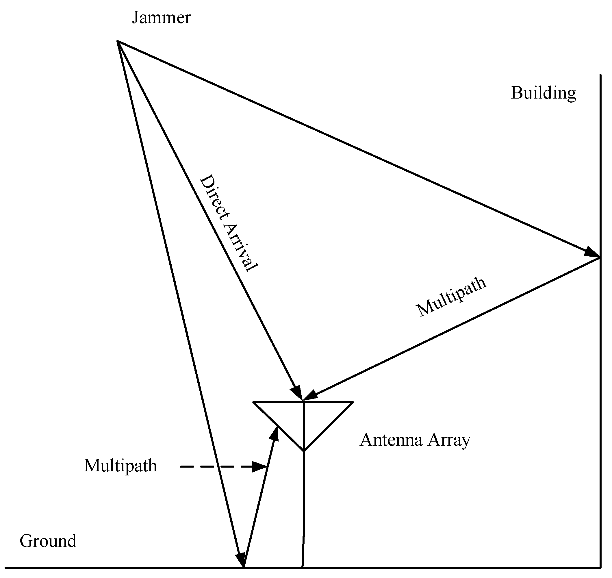
The multipath effect is related to the nature of the reflector around the antennas and varies with the surrounding environment. Interference may be reflected by buildings or obstacles, and the interference may be reflected several times. The direct and multipath interference could be superimposed and propagated to the antenna port. Propagation scenarios of direct and multipath interference are shown in Figure 3.
Based on the above-mentioned propagation scenarios, the difference between the direct and multipath interference is reflected in the amplitude and delay. The mathematical expression of the interference multipath model can be expressed as:
j ( t ) = a ( θ D ) j D ( t ) + i = 1 α i a ( θ P i ) j D ( t τ i )
where a ( θ D ) is the steering vector of interference, j D ( t ) is the direct interference, θ D is the direct incident angle of the interference, α i is the attenuation coefficient of the multipath interference, a ( θ P i ) is the steering vector for interference multipath, θ P i is the incident angle of the interference multipath, and τ i is the delay difference that the direct and multipath interference reach to the antenna port surface. i is the multipath number.
The propagation delay can be equivalent to a filter. Assuming that the filter transfer function is H P ( ω ) = [ H 1 ( ω ) H 2 ( ω ) H N ( ω ) ] , H n ( ω ) corresponds to the transfer function in n element. Thus, the model in Equation (1) can be further expressed as:
j ( t ) = a ( θ D ) j D ( t ) + i = 1 α i a ( θ P i ) j D ( t ) H P i ( ω ) = ( a ( θ D ) + i = 1 α i a ( θ P i ) H P i ( ω ) ) j D ( t )
The steering vector can also be regarded as a filter. Thus, the above equation can be expressed as:
j ( t ) = H ( ω ) j D ( t )
The above equation is an equivalent model for multipath. According to the equivalent model, it can be seen that the direct and multipath mixed signal is equivalent to the direct signal through a filter group. The H ( ω ) in the above equation is the equivalent filter group.

3. Impact of Multipath on Anti-Jamming

3.1. Space Only Processing

The SOP model is shown in Figure 4 [23].
In the above SOP model, the received signal and array weightings can be represented as:
x = [ x 1 x 2 x N ]
w = [ w 1 w 2 w N ]
The array output can be expressed as:
y = x 1 w 1 + x 2 w 2 + + x N w N = w T x
Usually, the interference power is much higher than the noise and signal power. In order to ease calculation, the interference cancellation ratio (ICR) can be denoted as:
ICR = P i n P o u t
where P i n and P o u t are the array input and output power, respectively.
Power inversion (PI) is a criterion for anti-jamming without any priori information, which can generate nulls in the strong interference direction. In the condition of strong interference and weak signal, especially in GNSS receivers, the PI is useful in engineering. Its constraint can be expressed as [24]:
{ min w { w H R x x w } s . t .     w H b = 1
where b = [ 1 0 0 ] T is the constraint vector, and R x x is the correlation matrix of the received data that could be expressed as:
R x x = E [ x x H ]
The weights can be further expressed as:
w = μ R x x 1 b
where μ is a normalized constant.
The anti-jamming performance of SOP is limited by DoF (Degree of Freedom). If the antenna element is N, the maximum number of interferences that can be suppressed is N-1. The multipath interference is treated as the normal direct interference, which would lose the array DoF. When the total number of direct and multipath interference still does not exceed the array DOF, the multipath would not affect the anti-jamming performance. However, when the total number exceeds the array DoF, the anti-jamming performance would dramatically drop.

3.2. Space-Time Adaptive Processing

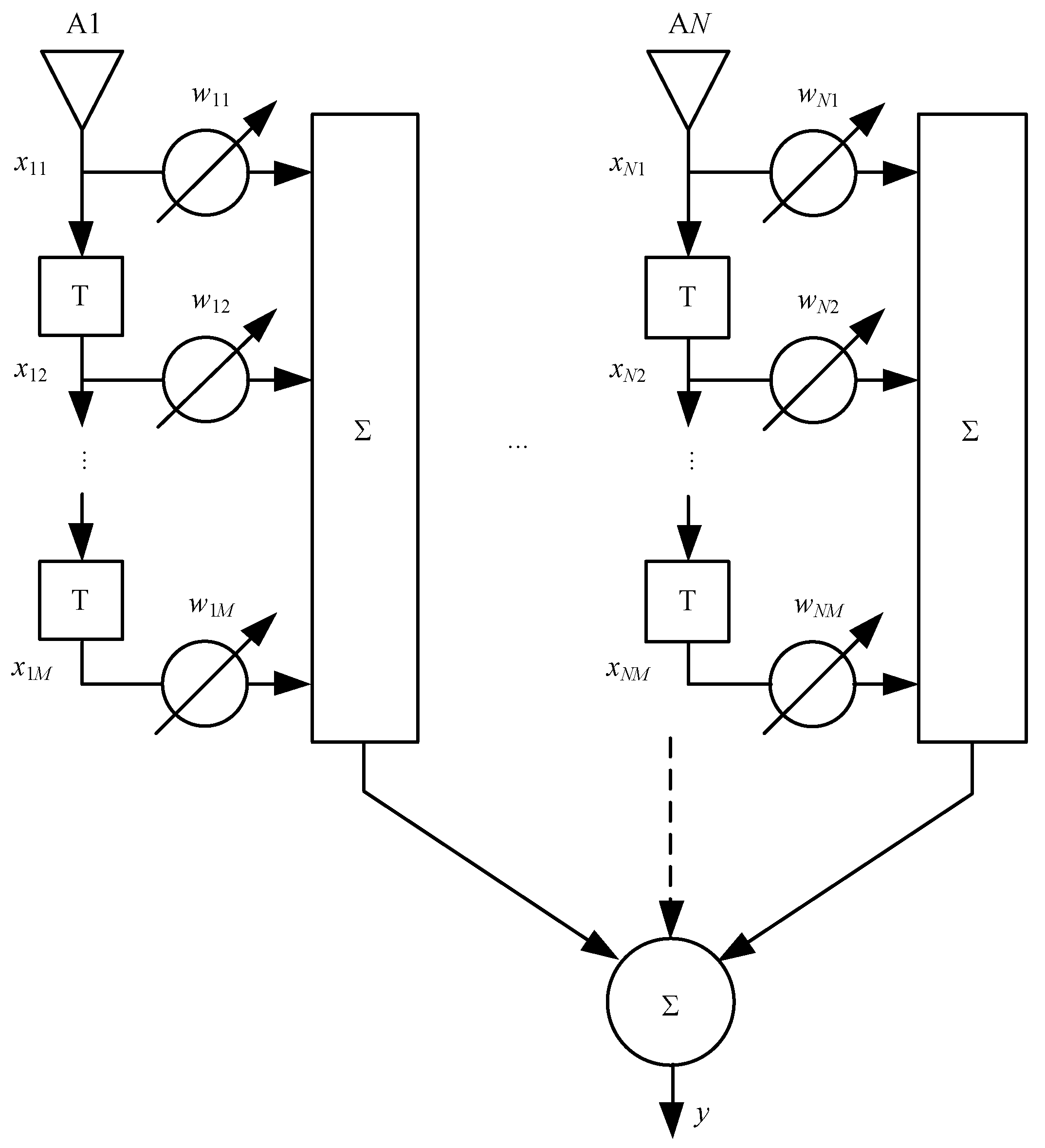
The STAP with N elements M taps is shown in Figure 5 [25,26,27].
According to the above STAP model, the received data in different sampling time could form a new data vector that could be expressed as:
x = [ X T ( t ) X T ( t T ) X T ( t ( M 1 ) T ) ] T
where X ( t ) is the received data vector at the time of t .
Array weightings could be written as:
w = [ w 11 , ... , w N 1 , ... , w 1 M , ... , w N M ] T
According to the space-time received data that is shown in Equation (17), the array weightings generator method is the same with SOP.
STAP has obvious advantages compared to the SOP. Without increasing the antenna elements, the DoF of interference suppression can greatly increase, and its interference suppression capability has a quality improvement [28]. In addition, STAP could mitigate the impact of non-ideal characteristic in antennas to anti-jamming.
According to the equivalent model of the interference multipath, it can be equivalent that direct interference reach to the antenna array, but the non-ideal characteristics of the antennas is increased. However, the STAP is able to solve the non-ideal characteristics of the antenna. Therefore, STAP may solve the effect of interference multipath on anti-jamming performance.

4. Simulation Experiments

The simulation experiments are performed in the computer with Lenovo W540, and the software is matlab2010a. In this simulation experiment, unless otherwise specified, the parameter settings are in Table 1 [29].

4.1. Verification for Equivalent Model

Two groups of multipath models were adopted to verify the correctness of the equivalent model. The parameters of the two groups of multipath models are as in Table 2:
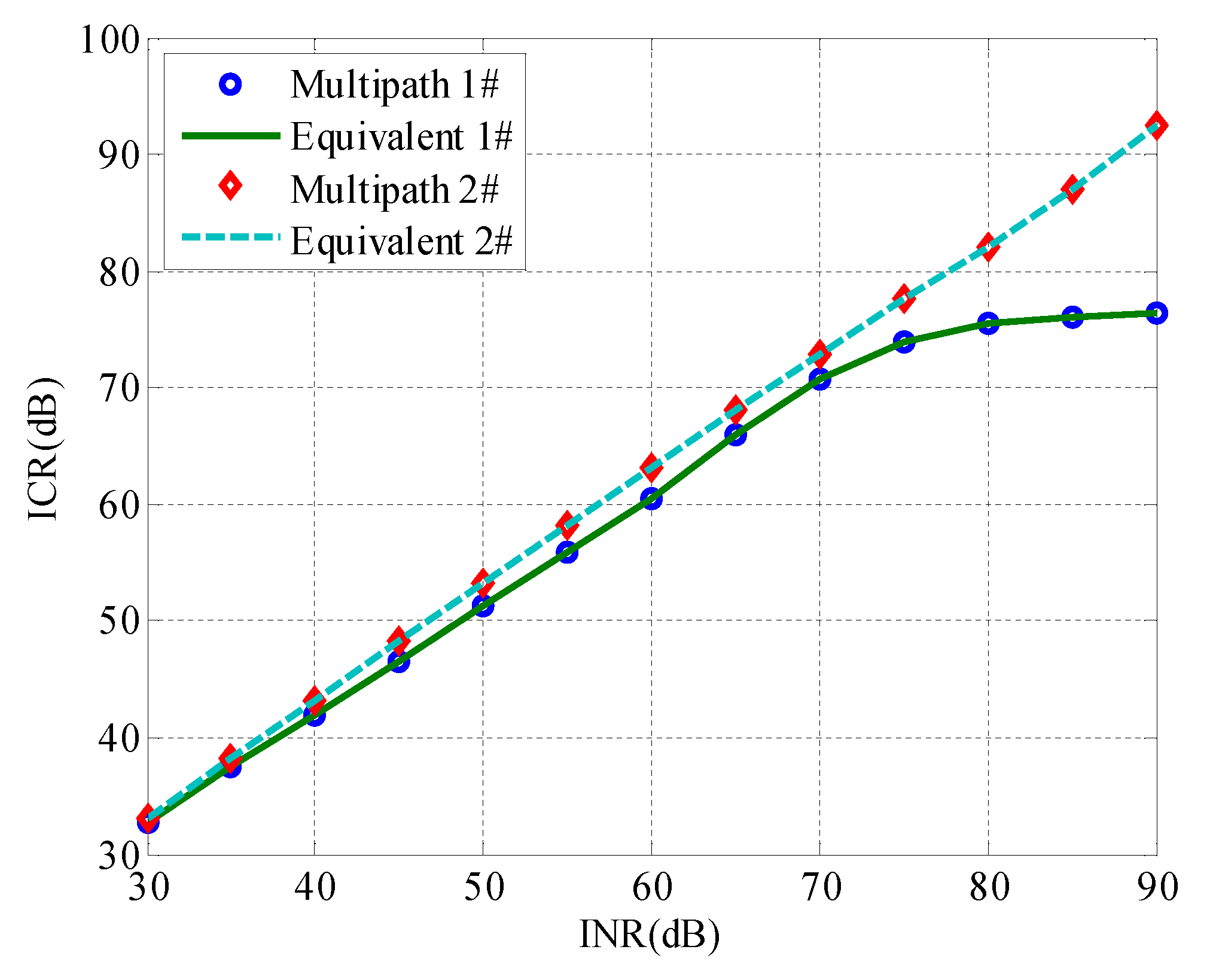
In this simulation, there are two jammers, and each jammer has one multipath. The INR is set from 30 dB to 90 dB, and its step is 5 dB. Under the different INR conditions, the SOP anti-jamming method is adopted. The ICRs for the multipath model and the equivalent model are shown in Figure 6.
As can be seen from the above figure, under the same conditions, the ICRs for the multipath model and the equivalent model are completely coincided, which can prove that the equivalent model is effective.
The condition is the same with the above simulation, but the STAP is used. The STAP is equipped with four taps. The experiment result is shown in Figure 7.
The anti-jamming performance for STAP is significantly higher than SOP. Regardless of SOP and STAP, the anti-jamming performance of the normal multipath model and the equivalent multipath model completely coincide, which indicates the effectiveness of the equivalent multipath model. The equivalent multipath model provides the basis to suppress the direct and multipath interference.

4.2. Simulation for SOP

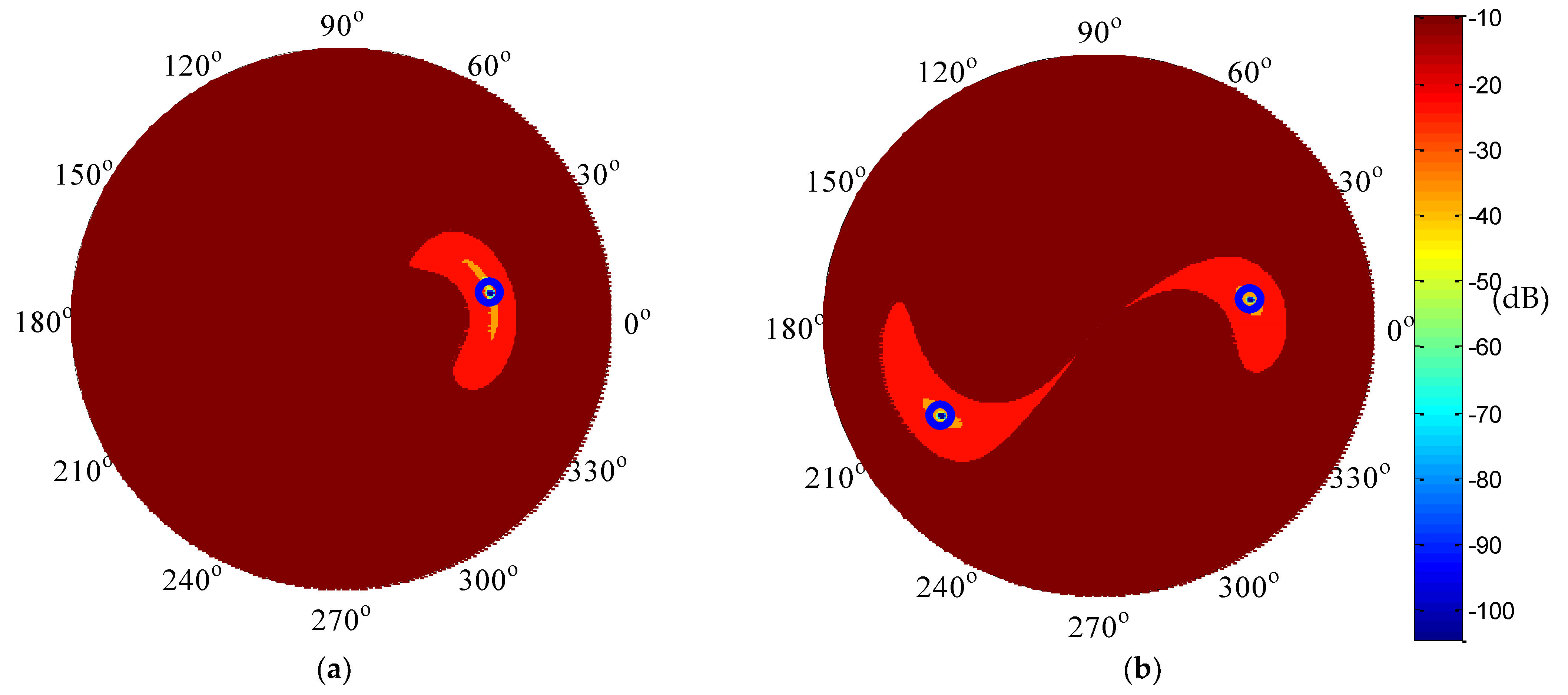
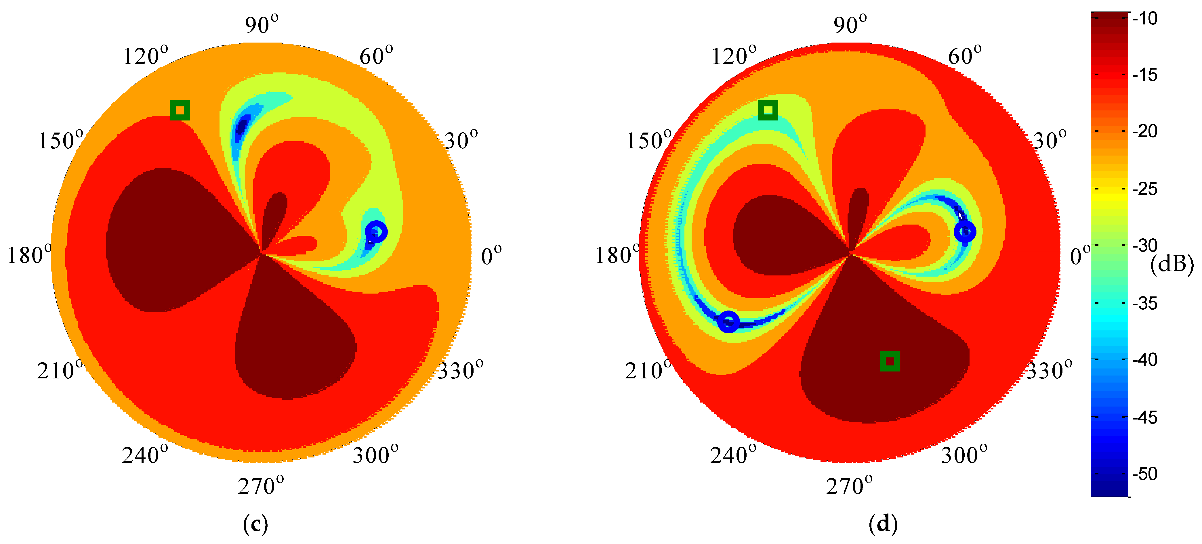
Four conditions, which are single interference without multipath, single interference with single multipath, two interferences without multipath, and two interferences with two multipath, are adopted. The array patterns with SOP are shown in Figure 8.
The four elements are adopted, so its DoF is 3, and it can suppress up to three interferences. In the above figure, when the total number of direct and multipath interference is less than three, the synthetic array can accurately form the null in the direct and multipath direction. In the case of two interferences with multipath, it is equivalent to the presence of four interferences from different directions, which is beyond the array DoF, so the direct and multipath interference cannot be effectively suppressed. In Figure 8d, there is a multipath in the direction of (290°, 40°), but the null is not formed in this direction on the pattern.
The ICRs of the above four cases are shown in Table 3.
Table 3 corresponds to Figure 8. When the total number of direct and multipath interferences is within the range of DoF, the direct and multipath interferences can be effectively suppressed. However, when the total number exceeds the DoF, the anti-jamming performance would drop significantly. In the above table, when the condition is two interferences with multipath, the input INR is 83 dB, but the output ICR is only 39 dB.

4.3. Simulation for STAP

Four multipath models are set, and they are all within two interferences and two multipaths. The multipath parameters are in Table 4:
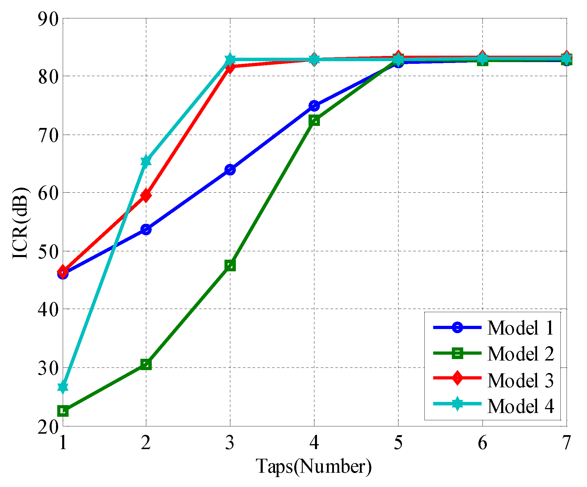
The number of time-domain taps is the key parameter for STAP. Under the conditions of the above four models, the effect of the number of taps on ICR is shown in Figure 9.
According to Figure 9, when the taps are small, different multipath models would lead to the different ICRs, and ICRs show an upward trend with the taps increasing. However, when the taps are large enough, the ICRs of the four models tend to be the same value that is approximately equal to the input INR. It illustrates that the STAP with increasing taps can solve the effects of the different multipaths.
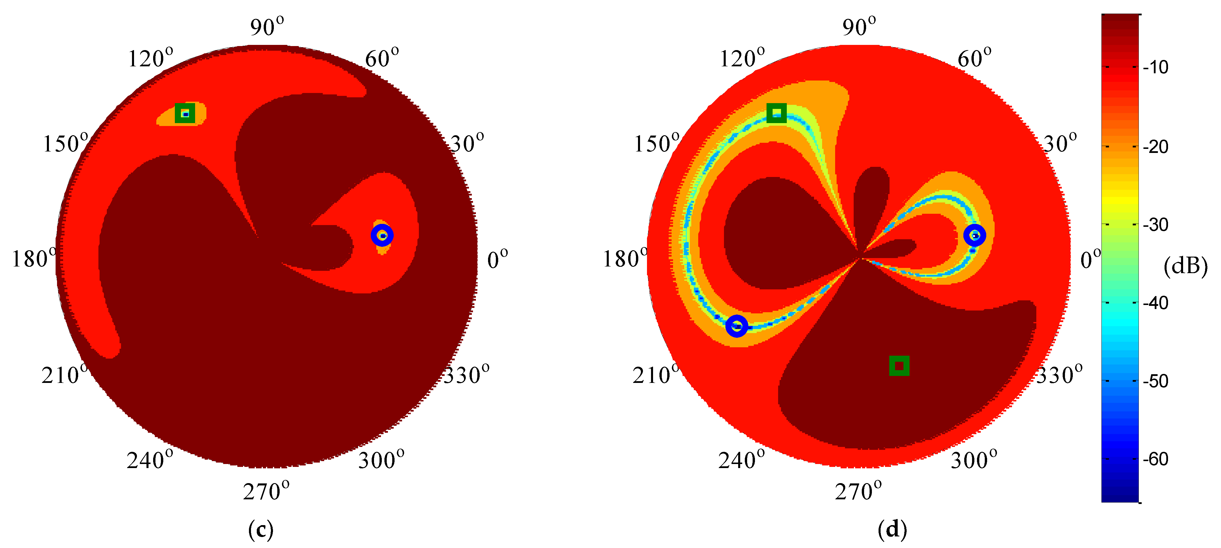
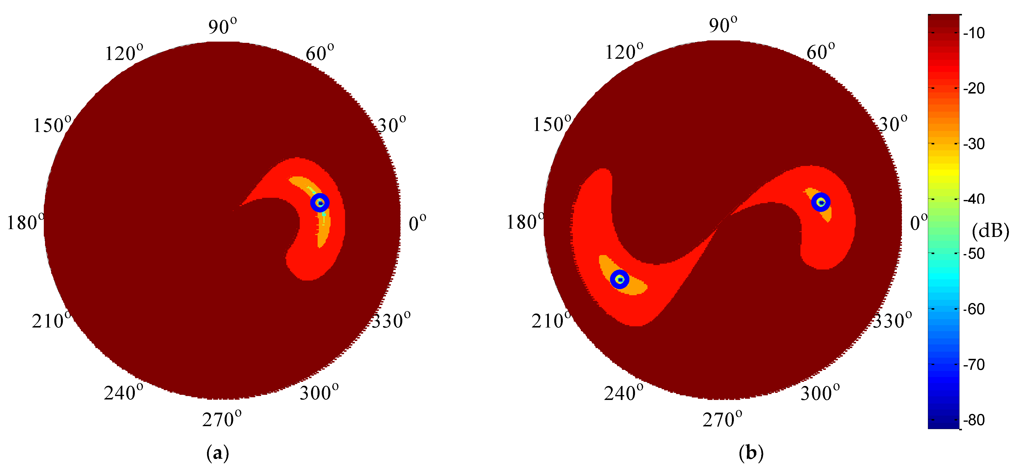
In model 1, if the time-domain taps are 5, according to Figure 9, the direct and multipath interference can be effectively suppressed. In the same case of Figure 8, if the STAP is adopted, the array patterns are shown in Figure 10.
In the above figure, the interference directions are marked with the blue cycle, and the multipath directions are marked with the green square. Under the condition of no multipath, the synthetic array pattern can accurately form the null in the interference directions. When the multipath is present, the synthetic array pattern can also form the null in the interference direction, but the null is not formed in the multipath direction. The interference suppression performance in the four cases is shown in Table 5.
According to the above table, in all cases, the interference and multipath have been effectively suppressed.
Figure 10 and Table 5 appear to be contradictory, because the direct and multipath interferences in Table 3 are effectively suppressed, but the synthetic array in Figure 8 does not form a null in the multipath direction. This is because there is an FIR filter behind each element in STAP, and the direct and multipath interference have the same baseband data. Since the interference power is greater than the multipath power, the FIR filter will compensate the difference of amplitude and delay between direct and multipath interference, and the multipath can be compensated to the equivalent direct interference. Therefore, in the synthetic array pattern, the null is only formed in the interference direction.

4.4. Impact of Bandwidth on Anti-Jamming

Studies have shown that the wider interference bandwidth would result in more difficulty suppressing the interference. The signal bandwidth is fixed, but the interference bandwidth may be faced with a variety of forms. The interference may be a continuous wave, and the interference bandwidth may cover the entire signal band. Increasing the navigation signal bandwidth is an effective way to improve the navigation and positioning accuracy. In the process of GPS signal development, the signal bandwidth is increasing. When the GPS modern plan is completed, the L1 band will contain three kinds of signals, which are C/A code, P(Y) code, and M code signal, respectively. The bandwidths of the three signals are 2.046 MHz, 20.46 MHz, and 30.69 MHz, separately, so the maximum interference bandwidth is 2.046 MHz, 20.46 MHz, and 30.69 MHz [30,31,32]. This simulation considers that the interference bandwidth is the maximum. Hence, the different signals would have different antenna array anti-jamming performance. Under the same interference multipath, this simulation will compare the anti-jamming performance of the C/A code, P(Y) code, and M code signal.
The experimental conditions are in Table 6:
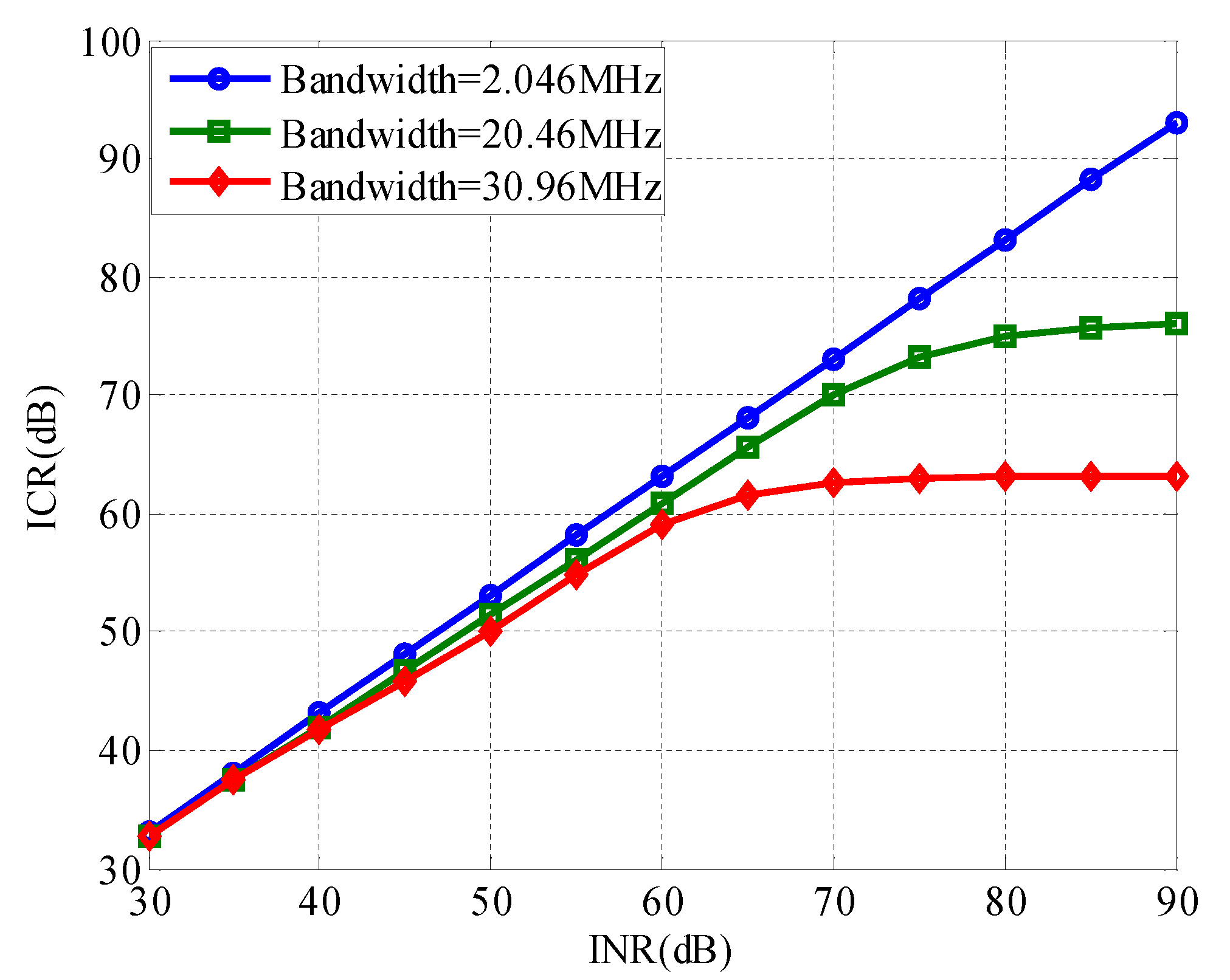
Assuming that the INR traverses from 30 dB to 90 dB with an interval of 5 dB, STAP is adopted, and the tap number in time domain is 4. In the case of the same array style, interference and multipath, the interference suppression performance of three different interference bandwidths is shown in Figure 11. As can be seen from the figure, different interference bandwidths have different interference suppression performance under the same experimental conditions. The wider the interference bandwidth, the weaker the interference suppression performance.
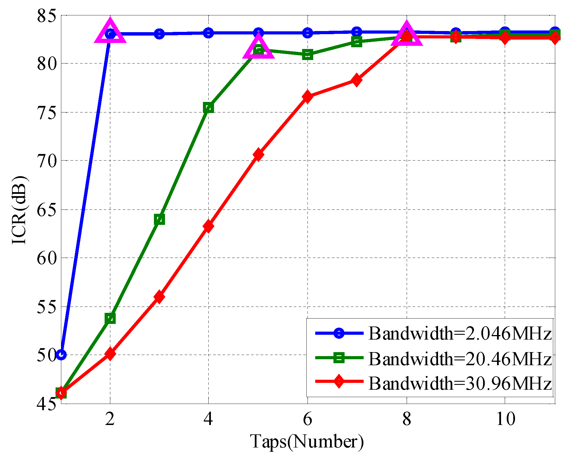
Section 3.2 and Section 4.3 pointed out that in STAP, the number of time domain taps can affect the interference suppression performance, and the more the number of time domain taps, the better the interference suppression performance. Assume that each interference INR is 80 dB, interference with the multipath case is the same with Table 4. In the case of different interference bandwidth, the effect of the number of time domain taps on the interference suppression performance is shown in Figure 12.
Regardless of the interference bandwidth, the interference suppression performance tends to increase with the increase of the number in time domain taps, and the sum of the interference suppression ratio is close to the input INR, indicating that the interference is effectively suppressed. We think that there is an optimal number of time domain taps, that is, with the increase in the number of time domain taps, ICR showed a rising trend, when the ICR rises to a certain extent, or reaches the limit, when the time domain taps are the best of. In the above figure, the optimal time domain taps for different interference bandwidths are marked with mage triangles. Obviously, different interference bandwidths have different optimal time domain taps, and the interference bandwidth is wider, and the optimal number of time domain taps is larger. Increasing the number of time domain taps can suppress the interference bandwidth and the multipath.

5. Conclusions

In this paper, we have analyzed the impact on the anti-jamming performance of jammer multipath in GNSS antenna array receivers. The characteristic of jammer multipath is studied, and the study has been developed through theoretical analysis and simulation experiment.
The outcome of the study is the following:
(1)
Interference multipath is equivalent to the direct interference through a filter, and multipath attenuation degree and delay are reflected in this filter. Direct interference and multipath interference have the same baseband signal, but the amplitude and the delay for these two interferences are different. The mix interference with direct and multipath interference can be equivalent to the direct interference through a filter.
(2)
Interference multipath would affect the performance of the SOP, which mainly reflects that the DoF would be a loss. When the sum number of the direct and multipath interference is still within the array DoF, the multipath would not affect the anti-jamming performance. The SOP could not distinguish the direct interference and multipath interference, and the multipath interference is seen as the direct interference.
(3)
The STAP can suppress the interference multipath, and its performance is related to the time-domain taps. Under the conditions allowed by hardware resources, increasing the taps can reduce the effect of interference multipath.
(4)
Under the same multipath model and anti-jamming condition, the interference bandwidth is wider, and the interference suppression is more difficult. However, the STAP with more taps may equalize the difference.

Author Contributions

L.H. performed the theoretical study, conducted the experiments, processed the data, and wrote the manuscript. Z.L. designed the system, provided research suggestions, and revised the manuscript together with Z.X. and J.S. C.R. helped in performing the experiments. B.L. provided the experiment equipment and suggestions for the manuscript. All authors have read and agreed to the published version of the manuscript.

Funding

This research was supported in part by the Natural Science Foundation of China (NSFC) grants 62003354.

Institutional Review Board Statement

Not applicable.

Informed Consent Statement

Not applicable.

Acknowledgments

The authors would like to thank the editors and reviewers for their efforts to help the publication of this paper.

Conflicts of Interest

The authors declare no conflict of interest.

References

  1. Ladina, S.; Michael, M.; Christoph, M. Impact of GPS processing on the estimation of snow water equivalent using refracted GPS signals. IEEE Trans. Geosci. Remote Sens. 2020, 58, 123–135. [Google Scholar]
  2. Zhang, P.; Tu, R.; Zhang, R.; Gao, Y.; Cai, H. Combining GPS, BeiDou, and Galileo Satellite Systems for Time and Frequency Transfer Based on Carrier Phase Observations. Remote Sens. 2018, 10, 324. [Google Scholar] [CrossRef] [Green Version]
  3. Chen, H.; Niu, F.; Su, X.; Gegn, T.; Liu, Z.; Li, Q. Initial Results of Modeling and Improvement of BDS-2/GPS Broadcast Ephemeris Satellite Orbit Based on BP and PSO-BP Neural Networks. Remote Sens. 2021, 13, 4801. [Google Scholar] [CrossRef]
  4. Mohamed, T.; Michael, J.; Haidy, E.; Aboelmagd, N. GPS Swept Anti-Jamming Technique Based on Fast Orthogonal Search (FOS). Remote Sens. 2021, 21, 3706. [Google Scholar] [CrossRef]
  5. Lu, Z.; Chen, F.; Xie, Y.; Sun, Y.; Cai, H. High Precision Pseudo-Range Measurement in GNSS Anti-jamming Antenna Array Processing. Electronics 2020, 9, 412. [Google Scholar] [CrossRef] [Green Version]
  6. Xu, W.; Xing, W.; Fang, C.; Huang, P.; Tan, W.; Gao, Z. RFI Suppression for SAR Systems Based on Removed Spectrum Iterative Adaptive Approach. Remote Sens. 2020, 12, 3520. [Google Scholar] [CrossRef]
  7. Bertold, V.D.B.; Sofie, P. Keeping UAVs under control during GPS jamming. IEEE Syst. J. 2019, 13, 2010–2021. [Google Scholar]
  8. Jalal, B.; Yang, X.; Liu, Q. Fast and Robust Variable-Step-Size LMS Algorithm for Adaptive Beamforming. IEEE Antennas Wirel. Propag. Lett. 2020, 19, 1206–1210. [Google Scholar] [CrossRef]
  9. Zhang, Y.D.; Amin, M.G. Anti-Jamming GPS Receiver with Reduced Phase Distortions. IEEE Signal Process. Lett. 2012, 19, 635–638. [Google Scholar] [CrossRef]
  10. Song, J.; Lu, Z.; Xiao, Z.; Li, B.; Sun, G. Optimal Order of Time-Domain Adaptive Filter for Anti-jamming Navigation Receiver. Remote Sens. 2022, 14, 48. [Google Scholar] [CrossRef]
  11. Marathe, T.; Daneshmand, S.; Lachapelle, G. Assessment of Measurement Distortions in GNSS Antenna Array Space-Time Processing. Int. J. Antennas Propag. 2016, 2, 2154763. [Google Scholar] [CrossRef]
  12. Lu, Z.; Chen, H.; Chen, F.; Nie, J.; Ou, G. Blind Adaptive Channel Mismatch Equalization Method for GNSS Antenna Arrays. IET Radar Sonar Navig. 2018, 12, 383–389. [Google Scholar] [CrossRef]
  13. Xie, Y.; Li, Z.; Chen, F.; Chen, H.; Wang, F. The Unbiased Characteristic of Doppler Frequency in GNSS Antenna Array Processing. Int. J. Antennas Propag. 2019, 2019, 5302401. [Google Scholar] [CrossRef]
  14. Fante, R.L.; Vacarro, J.J. Cancellation of Jammers and Jammer Multipath in a GPS Receiver. IEEE Trans. Aerosp. Electron. Syst. Mag. 1998, 11, 25–28. [Google Scholar] [CrossRef]
  15. Kogon, S.M.; Williams, D.B.; Holder, E.J. Exploiting coherent multipath for mainbeam jammer suppression. IET Radar Sonar Navig. 1998, 145, 303–308. [Google Scholar] [CrossRef]
  16. Fante, R.L.; Torres, J.A. Cancellation of Diffuse Jammer Multipath by an Airborne Adaptive Radar. IEEE Trans. Aerosp. Electron. Syst. 1995, 31, 805–820. [Google Scholar] [CrossRef]
  17. Lu, Z.; Nie, J.; Chen, F.; Ou, G. Impact on Anti-jamming Performance of Channel Mismatch in GNSS Antenna Arrays Receivers. Int. J. Antennas Propag. 2016, 2016, 1909708. [Google Scholar] [CrossRef]
  18. Caizzone, S.; Buchner, G.; Elmarissi, W. Miniaturized dielectric resonator antenna array for GNSS applications. Int. J. Antennas Propag. 2016, 2016, 2564087. [Google Scholar] [CrossRef]
  19. Chen, F.; Nie, J.; Li, Z.; Wang, F. Multitone-based Non-linear Phase Variation Estimation for Analog Front-Ends in GNSS Receivers. China Satell. Navig. Conf. 2014, 1, 619–627. [Google Scholar]
  20. Lu, Z.; Nie, J.; Wan, Y.; Ou, G. Optimal reference element for interference suppression in GNSS antenna arrays under channel mismatch. IET Radar Sonar Navig. 2017, 11, 1161–1169. [Google Scholar] [CrossRef]
  21. Sara, J.H.; Nagaraj, C.S.; Dennis, M.A. Fitlering and quantization effects on GNSS successive interference cancellation. IEEE Trans. Aerosp. Electron. Syst. 2020, 56, 924–936. [Google Scholar]
  22. Chen, F.; Nie, J.; Li, B.; Wang, F. Distortionless space-time adaptive processor for GNSS receiver. Electron. Lett. 2015, 51, 2138–2139. [Google Scholar] [CrossRef]
  23. Fante, R.L.; Vaccaro, J.J. Wideband Cancellation of Interference in a GPS Receive Array. IEEE Trans. Aerosp. Electron. Syst. 2000, 36, 549–564. [Google Scholar] [CrossRef]
  24. Compton, R.T. The power-inversion adaptive array: Concept and performance. IEEE Trans. Aerosp. Electron. Syst. 1979, 15, 803–814. [Google Scholar] [CrossRef]
  25. Lu, Z.; Nie, J.; Chen, F.; Chen, H.; Ou, G. Adaptive Time Taps of STAP Under Channel Mismatch for GNSS Antenna Arrays. IEEE Trans. Instrum. Meas. 2017, 66, 2813–2824. [Google Scholar] [CrossRef]
  26. Liu, Y.; Cao, Y.; Tang, C.; Chen, J.; Zhao, L.; Zhou, S.; Hu, X.; Tian, Q.; Yang, Y. Pseudorange Bias Analysis and Preliminary Service Performance Evaluation of BDSBAS. Remote Sens. 2021, 13, 4815. [Google Scholar] [CrossRef]
  27. Alexandre, M.; Alvaro, S.; Jean-Paul, B.; Félix, P.; Sylvain, L. Analysis of GNSS Displacements in Europe and Their Comparison with Hydrological Loading Models. Remote Sens. 2021, 21, 4523. [Google Scholar]
  28. Xue, B.; Wang, H.; Yuan, Y. Performance of BeiDou-3 signal-in-space ranging errors: Accuracy and distribution. GPS Solut. 2021, 25, 23. [Google Scholar] [CrossRef]
  29. Zhang, Z.; Li, B.; Nie, L. Initial assessment of BeiDou-3 global navigation satellite system: Signal quality, RTK and PPP. GPS Solut. 2019, 23, 24. [Google Scholar] [CrossRef]
  30. Zhang, Y.; Kubo, N.; Chen, J.; Wang, J.; Wang, H. Initial Positioning Assessment of BDS New Satellites and New Signals. Remote Sens. 2019, 11, 1320. [Google Scholar] [CrossRef] [Green Version]
  31. Yang, H.; Zhou, B.; Wang, L.; Wei, Q.; Ji, F.; Zhang, R. Performance and Evaluation of GNSS Receiver Vector Tracking Loop Based on Adaptive Cascade Filter. Remote Sens. 2021, 13, 1477. [Google Scholar] [CrossRef]
  32. Zhou, Q.; Zheng, H.; Wu, X.; Yue, X.; Chen, Z.; Wang, Q. Fractional Fourier Transform-Based Radio Frequency Interference Suppression for High-Frequency Surface Wave Radar. Remote Sens. 2020, 12, 75. [Google Scholar] [CrossRef] [Green Version]
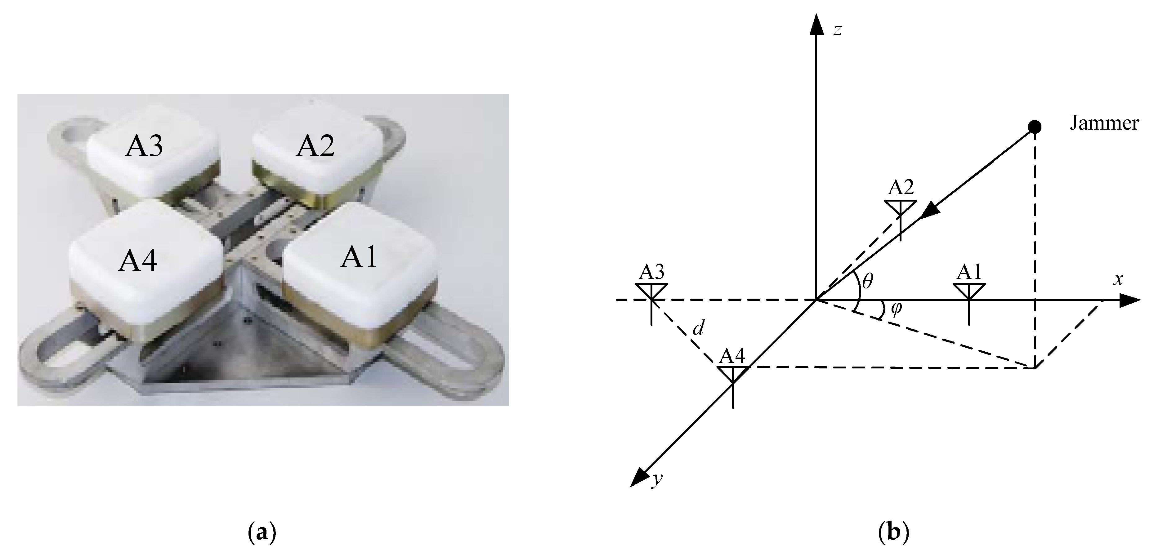
Figure 1. Antenna array (a) array picture and (b) array model.
Remotesensing 14 00350 g001
Figure 2. Antenna array structure.
Remotesensing 14 00350 g002
Figure 3. Antenna array structure.
Remotesensing 14 00350 g003
Figure 4. SOP model.
Remotesensing 14 00350 g004
Figure 5. STAP model.
Remotesensing 14 00350 g005
Figure 6. Verification for the equivalent model that used SOP.
Remotesensing 14 00350 g006
Figure 7. Verification for the equivalent model that used STAP.
Remotesensing 14 00350 g007
Figure 8. Array patterns in SOP: (a) one jammer without multipath, (b) two jammers without multipath, (c) one jammer with one multipath, and (d) two jammers with two multipaths.
Remotesensing 14 00350 g008aRemotesensing 14 00350 g008b
Figure 9. Impact of taps on ICR with multipath.
Remotesensing 14 00350 g009
Figure 10. Array patterns in STAP: (a) one jammer without multipath, (b) two jammers without multipath, (c) one jammer with one multipath, and (d) two jammers with two multipath.
Remotesensing 14 00350 g010aRemotesensing 14 00350 g010b
Figure 11. ICR for different bandwidths with jammer multipath.
Remotesensing 14 00350 g011
Figure 12. Impact of taps on ICR with different bandwidth.
Remotesensing 14 00350 g012
Table 1. Public parameter settings.
Parameter TypeParameter Value
Antenna array typefour-element square
Sampling frequency62 MHz
Intermediate frequency15 MHz
Jammer typeGaussian white noise
Jammer #1 DOA(10°, 40°)
Jammer #2 DOA(210°, 30°)
Multipath #1 decay0.1
Multipath #2 decay0.01
Multipath #1 delay100 ns
Multipath #2 delay200 ns
Multipath #1 DOA(120°, 20°)
Multipath #2 DOA(290°, 40°)
Table 2. Two multipath models.
Model 1#Model 2#
Amplitude(0.1, 0.01)(0.05, 0.2)
Delay (ns)(100, 200)(20, 60)
Table 3. ICR with SOP in different conditions.
INR (dB)ICR (dB)
One interference without multipath8080
Two interferences without multipath8383
One interference with multipath8080
Two interferences with multipath8339
Table 4. Four multipath models.
Model 1Model 2Model 3Model 4
Amplitude(0.1, 0.01)(0.05, 0.2)(0.1, 0.01)(0.05, 0.2)
Delay (ns)(100, 200)(100, 200)(20, 60)(20, 60)
Table 5. ICR with STAP in different condition.
INR (dB)ICR (dB)
One interference without multipath8080
Two interferences without multipath8383
One interference with multipath8080
Two interferences with multipath8382
Table 6. Parameter settings.
Parameter TypeParameter Value
Jammer number2
Jammer DOA(10°, 40°) and (210°, 30°)
Multipath number2
Multipath amplitude0.1 and 0.01
Multipath delay100 ns and 200 ns
Multipath DOA(120°, 20°) and (290°, 40°)
Publisher’s Note: MDPI stays neutral with regard to jurisdictional claims in published maps and institutional affiliations.