Abstract
With the development of intelligent transportation, radar and communication on moving platforms are competing for the spectrum. In this paper, we propose and demonstrate a new algorithmic framework for radar-communication spectral coexistence system on moving platform with mutual interference suppression, in which communication rate and the radar signal-to-interference-plus-noise ratio (SINR) are simultaneously optimized, under the energy constraints for the two systems and the radar constant modulus constraint. The radar spatial-temporal filter at the receiver and transmitting waveform are optimized, while the codebook matrix is optimized for the communication system. To cope with the established non-convex problem with triplet variables, we decouple the original problem into multiple subproblems, for which an alternating algorithm based on iterative procedures is derived with lower computational complexity. Specifically, the subproblems of communication codebook and radar filter design are convex and the closed-form solutions can be easily obtained, while the radar waveform optimization is non-convex. Then we propose a novel scheme by exploiting the alternating direction method of multipliers (ADMM) based on minorization-maximization (MM) framework. Finally, to reveal the effectiveness of the proposed algorithm in different scenarios, numerical results are provided.
1. Introduction
With the explosive growth of the wireless information transformation industry [1], the usage of radar is important in numerous civilian applications, including remote sensing, collision avoidance, and vehicles intelligent cruise control. Meanwhile, a large amount of spectrum resources are also occupied by the wireless communication for traffic control, autonomous driving, and information services [2,3]. For example, the high UHF radars overlap with GSM communication systems, and the S-band radar systems partially overlap with Long Term Evolution and WiMax systems [4,5]. Hence, the available spectrum is becoming more and more cramped. To deal with such issue, spectrum sharing between radar and wireless communication, as an emerging topic, has attracted considerable attentions and yielded several literatures recently [6,7,8,9,10]. In general, there are two main research directions. The first research direction refers to the Dual-functional Radar-Communication Systems, for which a unique platform integrating radar with communication functions is developed. This joint radar communication (JRC) model enhances information sharing and has the advantages of low cost, small size, low power consumption, spectrum sharing, performance improvement and security [5]. Another research direction concentrates on the radar-communication coexistence systems that operate at the same frequency band, which results in the joint design of spectrally overlaid systems. In this case, the mutual interference between different systems will lead to great challenge to the required Quality of Service (QoS) even with low-level cross interfering signals [11].
In spectrally overlaid systems, different subsystems have conflicting objective performances [12], which will lead to the mutual interference between the subsystems. Therefore, mutual interference suppression is needed to enable the spectrum sharing and guarantee the required QoS. Early studies were mainly based on transmitter design and evaluated the performance of coexistence systems via controlling the mutual interference produced by competing subsystems, e.g., the radar waveform design addressed a non-convex optimization in a spectrally crowded environment [13]; the codebook design improved the communication rate in the presence of strong radar interference [14]. These literatures on spectrum sharing address interference management for single-antenna radar or communication systems. To further realize the interference management in multi-antenna systems, the radar-communication coexistence system using MIMO structure were introduced in [15,16], which both MIMO radar and MIMO communication system use single antenna transmitter and receiver with long separation. The cooperation between the two systems means that the antenna positions between the two systems are shared in terms of knowledge sharing [17]. In addition, thanks to the recent developments of cognitive wireless networks, intellisense provides the possibility for the coexistence of radar system and existing communication system. Radar and communication systems could be conscious of each other’s existence by sharing messages, thus facilitating the joint design between radar and communication systems [18,19,20]. The spectrum sharing co-design of radar and communication systems using MIMO technology was introduced in [21,22], whereby the design degrees of freedom (DoFs) under control was adopted at all transmitters in the coexistence systems. Since, such co-design requires information sharing between subsystems, the payback would be less mutual interference and better figure of merit for the coexistence system. Since spatial-temporal processing has potential advantages in spectrum sharing, there have been growing interests in the usage of spatial-temporal processing architecture in the co-design of subsystems. Compared with the conventional spectrum sharing designs, the spatial-temporal processing architecture collects signals from numerous pulses and antennas, and accommodatively adjusts the radar spatial-temporal filter, which increases Doppler resolution and suppresses the clutter and mutual interference simultaneously. On the algorithmic side, the convex optimization technique, e.g., semidefinite relaxation technique, is usually developed for the joint design. However, such method suffered from high computational complexity [12,21].
In general, different critical issues for radar and communication system spectral coexistence are developed based on different figures of merits [23]. However, it is worth noting that few studies have addressed the issue of spectral coexistence on moving platforms, which exacerbates the location-induced interference and makes the co-design problem more challenging [24]. For example, as an emerging remote sensing medium, the rise of autonomous driving leads to increased highway capacity and passenger comfort, which requires reliable communications to transfer the state information of each platform [25]. In order to reduce the mutual interference between automotive radars using millimeter wave frequency modulated continuous wave radars under dense traffic conditions, several methods to reduce mutual interference have been proposed [26]. For example, [27] introduces the tunable Q-factor wavelet transform domain and applies it to separate the interference from target signals. In this spectrum sharing situation, the range-Doppler processing, detection, and dynamic range enhancement strategies for the radar in autonomous driving are involved [28,29]. Thus, major challenges in the application of autonomous driving are the vibration and motion of the platform. The interference mitigation of the autonomous driving also needs to be considered, including not only the self-interference, but also the cross interference from the communication system in spectrum sharing scenarios [30]. In addition, most of the existing designs focus on the optimization with single radar target. However, in real scenarios, the radar sometimes has to detect multiple targets, e.g., in multi-target tracking scenarios, in which the adaptive resource management for radar is necessary [31,32]. Moreover, the increasing number of constraints would exacerbate the computational burden.
Against the aforementioned background, a new algorithmic framework is proposed for the radar-communication spectrum coexistence system on moving platform. We presume the coexistence system is equipped with MIMO antennas and its spatial-temporal probing signal can be used as an additional DoFs. To cope with multiple targets, this paper will investigate the problem of spectrum sharing with a set of separated SINRs for radar. The DoFs under control consists of the spatial-temporal transmit waveform, the filter of receiver for the radar, and the spatial-temporal codebook matrix for the communication system. Then, under multiple constraints, the SINR of radar and communication rate are formulated for simultaneous optimization. Towards this end, an alternate iteration algorithm for multiple subproblems is contrived for solving the designed non-convex triplet variables problem. After a series of manipulations, two convex subproblems are formulated for communication codebook design and radar filter optimization respectively, and a non-convex architecture is derived for radar waveform. The convex subproblems could be solved easily in closed-form, while the non-convex subproblem can be solved by exploiting the alternating direction method of multipliers (ADMM) based on minorization-maximization (MM) framework [33]. Finally, a comprehensive performance assessment is provided.
Notations: denotes the complex Gaussian distribution with mean and variance . , and represent the transpose, Hermitian and conjugate operators, respectively. and denote the vectorization and determinant of the matrix . ⊙ and ⊗ denote the Hadamard operator and Kronecker operator respectively. and denote the diagonal operator and trace operator, respectively. As to a complex-valued vector , its real-valued forms is defined as . For a complex-valued matrix , the real-valued forms is given by . represents the positive part of .
2. Signal Model
As shown in Figure 1, assume two moving narrow band systems using the same frequency, where a communication system based on MIMO structure is equipped with transmit and receive elements, and a monostatic radar system with MIMO structure is equipped with transmit and receive elements [34]. We consider the cooperation is coordinated by the control center, which collects information from the two subsystems, computes jointly optimal designed parameters and sends each scheme back to the corresponding system. In this work, we address spectrum sharing during the phase that the receive antennas obtain measurements of the target returns. The information transformation between the receive antennas and control center, can be viewed as the interference between two communication systems and is out the scope of the paper [35]. During a Pulse Repetition Time, each transmit antenna of the radar transmits L pulses, denoted by vector , where is the radar transmit vector of the l-th epoch. Assume that the M radar far-field moving targets located at the range gate and azimuth , an observation signal for M radar targets at epoch l is modeled as [36,37,38]
where is the path loss of the m-th target, and , is the range cell index of the m-th radar target related to the range cell of interest. and represent the communication interference and clutter respectively. is the additive white Gaussian noise. For notational simplicity, we introduce with and denoting the transmit and receive steering vectors, respectively. By defining , , , and , we can have the whole observation vector with a compact form as
where
let represent the temporal steering vector with representing the m-th radar target Doppler frequency. is a transform matrix, and its -th element is given by
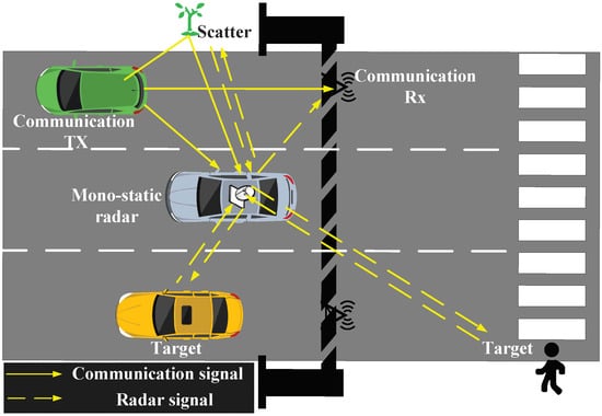
Figure 1.
A Photo illustration of Radar and Communication Spectral Coexistence on Vehicle Platform.
Moreover, assume the j-th clutter or the c-th interference from communication system is distributed in the range-azimuth bin , , . represents the number of range rings, and K denotes the number of discrete azimuth segments, then the clutter obeys the model
where denotes the complex amplitude with , and denote the normalized Doppler frequency and azimuth of the j-th clutter, respectively.
Suppose the normalized Doppler frequency with mean , where denotes the uncertainty of . Then the covariance matrix of clutter is given by
As to the m-th radar target at the range gate , the clutter covariance matrix with a compact form can be expressed as
where
with , and denoting the corresponding power of the j-th clutter.
In narrow band communication systems where the maximum excessive delay of P interference signals is much smaller than the sampling interval , i.e., [39], we get , , which means that P communication interferences fall in the same range ring to the radar receiver. In this case, we consider P channels for communication interference: the p-th path with angle of departure , angle of arrival and fading coefficient , the expression is written as
where represents the fading coefficient of the p-th propagation path, and is the p-th transmit steering vector from the communication systems. We thus define:
in which
and , where denotes the Doppler shift of the p-th communication signal. Then, the covariance matrix of communication interference will have a similar form as the clutter component (7), i.e.,
where the communication codewords are denoted by with [40]. In order to reduce the complexity of design, we only optimize the space-time covariance matrix .
Concerning the communication system, the received signal can be expressed as
where , is channel matrix. , , where represents the receive steering vector of the q-th path. Similar to the definition of (10), we set
where represents the fading coefficient of the q-th propagation path at the communication receiver, Q is the number of paths impacting on the communication receiver, and denotes the additive white Gaussian noise. It is supposed that the channel matrices , and are fully known at the spectral coexistence system. Practically, the information can be periodically communicated by a pilot channel [41,42]. However, the exact direction information may not be obtained because of the possible mismatches. Therefore, we assume that and are independent random variables and can be expressed as
where , , , are the uncertainties on the corresponding direction information.
3. Problem Formulation
Since improving the accuracy of parameter estimation and signal detection in presence of interference can be achieved by a higher SINR level, we take maximizing the output SINR as a criterion for radar transceiver design. Specifically, by assuming , the for the m-th target can be written as
where
with
denoting the interference term produced by the other radar targets.
For the radar, the SINR in (17) given the scope of inspection can be regarded as a relevant figure of merit. For this purpose, assuming , the figure of merit is given by
where is a positive weight. For simple numerical description, we define . Based on the above guidelines, for the communication system, the covariance matrix of the interference-plus-noise can be formulated as
In order to match , we define the “communication rate” of the space-time communication channel as
Our goal is to optimize the communication system rate and radar output SINR simultaneously. Due to the fact that the energy of the transmitter is limited in most cases and to obtain desirable properties according to envelope constancy and sidelobe levels with a reference signal , we require the shape of radar waveform with normalized transmitted energy satisfying [43]
where rules the degree of the similarity. The above constraint can be equivalently converted to
where represents a square matrix where all elements except -th element equal to 1 are 0. Regarding to the communication system, we put an energy constraint on the transmitter, namely
According to [44], the classic SINR maximization problem of radar can be solved via the MVDR criterion. Without loss of generality, by setting for with the constant , we reformulate the radar SINR as
Finally, we recommend minimizing an appropriate weighted radar residual interference power and communication rate, i.e.,
where represents the interference-plus-noise power, and is given by (22). Assuming that and are the corresponding achievable optima values. and are weighted parameters. Typically, , which reflects the degree of importance of the two conflicting objectives in the coexistence system. In the following section, we will derive the solutions to problem (27) through the proposed algorithm framework.
4. The Designed Alternating Procedure
Problem (27) is non-convex relating to the triplet parameters (, , ), and finding the solutions would cause a daunting complexity. We develop an alternating algorithm on the basis of the following iterative procedure.
4.1. Communication Transmit Codebook Optimization
Firstly, we optimize while and are fixed:
Theorem 1.
Let , then the residual interference-plus-noise of is given by
where is a positive item independent of . , and
Proof of Theorem 1.
It can be shown that the communication interference onto the radar can be expressed as
where
Based on (31), we have
which completes the proof. □
By exploiting Theorem 1, the subproblem (28) can be transformed as
which is a convex problem involving multiple matrix variables. Therefore, by using standard convex optimization techniques, the above problem can be solved with the complexity of . The Lagrange dual method is used for the problem (34) and thus a low-cost closed-form solution can be obtained. Ignoring the items that do not rely on , the Lagrangian of (34) can be expressed as
where is the dual variable. Then, the dual problem be formulated as
where denotes the duality function. In addition, since (34) is convex satisfying Slater’s condition and strong duality [45], i.e., the dual gap is set to zero. By using the "water-filling (WF)", the optimal solution can be indicated as
where denotes the optimal for a given , and denotes the right singularity matrix of , the expression is given as
, . r represents the rank of , denotes the i-th positive singular value of the matrix , and , where . can be obtained via the bisection method fulfilling the power constraint.
4.2. Radar Receive Filter Optimization
For the second step, given and , the optimization of the receive filter is solved by the MVDR criterion:
Thus the filter for each radar target can be computed.
4.3. Radar Transmit Waveform Optimization
In the third step, we consider to optimize with fixed and , for which the subproblem can be converted to
which is non-convex because of the right side of the cost function and the quadratic equation constraints. Generally, it is difficult to straightforwardly tackle such a non-convex problem and there is no closed-form solution. Therefore, we first derive a minorizing function for the communication rate (right-hand side) of the objective function, i.e., , and then an iteration procedure with lower computational complexity based on MM-ADMM is developed.
4.3.1. Minorizing Function Construction
We first simplify the radar interference term of the original problem before building the minorizing function for the transmission rate. The energy at the output of the radar filter can be rewritten as follows by ignoring the parts that don’t depend on in the first portion of the objective function in (40).
Following the same line of derivation, the filtered radar clutter power can be expressed as
with
For ease of notation, we set . The communication rate is convex in respect of , to tackle the maximizing problem, the rate is rewritten as
Next, we construct two functions that minorize and in (44), as a result of which the MM algorithm can be used to solve the problem (40).
Theorem 2.
Define and , assume is the feasible set for . As to any , a valid surrogate function, at the -th iteration, can be formulated as
where is a term independent of ,
with and .
Proof of Theorem 2.
As to the function , by exploiting the property of matrix determinant, we have:
Based on the Woodbury matrix identity, for given matrices , we have
Then, the inverse of the matrix in (49) becomes to
By exploiting the block matrix inversion property, the right-hand side of (51) can be transformed to . Note that is convex with respect to . The convex function can be minorized by its supporting hyperplanes, i.e.,
where denotes the gradient of at . Concerning the second term of (44), it is simple to demonstrate that function is a convex function with respect to and we have
where denotes the gradient of at . Ignoring the terms that do not depend on , (45) can be derived from (52) and (47).
To make the formulation of the minorizer (52) simpler, can be partitioned as
Then the expression of in (45) can be transformed as
which completes the proof. □
According to and omitting the constant terms, the problem (40) can be turned into:
where . Problem (56) is non-convex quadratically-constrained quadratic program (QCQP), which is difficult to solve. However, such a problem can be addressed using CVX tools with (see [46] for details). In the following, an iteration procedure with lower computational complexity based on MM-ADMM is developed.
4.3.2. Radar Transmit Waveform Optimization Based on ADMM
To overcome the problem(56), we exploit the ADMM algorithm. It can be shown that problem (56)’s first restriction can be equivalently rewritten as
Take note that the following decomposition is always valid
where is rank-one Hermitian matrix. Problem (56) is equivalent to
We assume that the real-valued forms of , , , , and are denoted by , , , and , respectively. Problem (59) can be recast into the following real-valued form by inserting the variables , and
4.3.3. Update of
The optimization of (62a) can be rewritten as
The first order optimality conditions for (63) are
where signifies a column vector of a-dimensional with all-zero entries, leading to
4.3.4. Update of
4.3.5. Update of
Problem (62d) can be rewritten as
The solution can be achieved via proximal algorithm, i.e.,
with .
4.3.6. Update of
As to the computational complexity for the developed formulation, the can be optimized by using WF with . The optimized can be obtained based on (39) with complexity . The complexity of is at each iteration due to the matrix inverse; the other variables requires the computational complexity linearly with [48]. Finally, Algorithm 1 summarizes the overall technique of the alternating approach. Notice that the above ADMM method which directly handles the transformed non-convex problem may not always ensure the convergence theoretically. Suitable initializations and penalty parameters are necessary to ensure convergence. Hence, the penalties are chosen based on the eigenvalues of in (60) and the initialization of is set to be [47] (Theorem 4).
In such monostatic radar and communication spectral coexistence system on moving platform, the cooperation is coordinated by the control center. The information from radar and communication systems is collected by the control center. However, such information will be aging or not usable due to time lag between the channel estimation phase/optimization phase and deployment phase. In order to improve the real-time performance, we will try to improve the hardware of each subsystem to enhance its own computing power, and cancel the control center in the future work. That is, the radar and communication systems calculate their own optimal signaling scheme through the collected information [49].
| Algorithm 1 Procedure for , and Optimization |
| Input:, , , , , . Initialize: Let , , , , ; Output: , , .
|
5. Results and Discussion
In simulations, the radar has transmit antennas and receive antennas, and the communication has transmit antennas and receiver antennas. We set as the code length. The noise variance of coexistence system is . We set for energy constraint of communication system. And with zero mean and unit variance, uses the Rayleigh fading channel.
As to the considered coexistence system, e.g., as shown in Figure 1, the vehicles in an intelligent transportation system that needs to share information in a rapidly changing environment, and the radar requires a wide Doppler range to detect fast vehicles and slow pedestrians. Thus, some other parameters can be given as follows. For the radar, the directions of two targets are located at and , respectively, with normalized Doppler frequencies and , respectively. The clutters are evenly distributed in with a discrete azimuth of 90 in each ring. Similarly, for all clutters, we consider and . For the mutual interference between two systems. We assumed that the azimuth of is distributed in , , and . As to , we assume that angle parameters are randomly distributed in with the associated Doppler shift of and . Except where otherwise noted, the uncertainties on the direction information are set as . The similarity parameter is set as . The radar reference waveform is exploited with Linear Frequency Modulation. The penalty parameters are set as . We set .
Firstly, we evaluate the convergence behavior of the proposed design versus . In Figure 2, the objective value under different outer iteration numbers is investigated. It can be shown that the proposed design converges for all values of the similarity parameter that are taken into consideration, and provides the best performance, which is reasonable because the larger similarity parameter could provide additional DoFs in procedure.
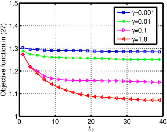
Figure 2.
The objective value with outer iteration number under different similarity parameter .
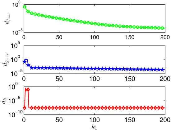
In Figure 3, the constraint convergence in optimization is examined. The residuals for auxiliary variables are defined as follows in the ADMM procedure:
As to better illustrate the constraint convergence in optimization, we set the termination tolerances in (72) as [50]. Figure 3 reports the residuals of the constraints from (60b) to (60d) versus of ADMM. It can be shown that the stopping criterion is satisfied for all considered constraints.
Figure 4 shows the radar cross-ambiguity function’s (CAF) [46] about the radar target response for outer iteration number . It can be observed that the main lobes are at the target location, null is at the communication interference location, and the clutter ridge is dispersed diagonally. Furthermore, it can be demonstrated that the value drops as the number of iterations increases in the interference region including clutter and the interference from communication system. This trend highlights that Algorithm 1 is able to suitably shape the CAF for interference suppression within small iterations, i.e., the proposed design provides fast convergence properties.
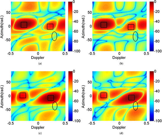
Figure 4.
Doppler-azimuth plane of CAF of radar multi-targets for outer iteration number : (a) and , , (b) and , , (c) and , , (d) and , (solid line rectangles and ellipse respectively denote the locations of the radar targets, the interference sources from communication system).
The performance of the developed design is next examined in relation to various mutual interference strengths with . As a benchmark, we also consider the objective values obtained by exploiting different algorithms: the Semi-Definite Programming (SDP) and randomization procedure (labeled as “Joint Design with SDP-R” ) for optimization [51], the transmit design for and optimization (labeled as “Transmit Optimized”), as well as the disjoint design, namely, no mutual interference management (labeled as “Uncooperative Optimized”). Figure 5 expresses the objective value in terms of for various levels of mutual interference channel. We can see that the objective value grows as the INR increases; the proposed joint design provides the best performance. The primary reason is that more DoFs can be achieved in the coexistence system, which also implies the necessity of the joint design for spectrum sharing system in practical applications. Correspondingly, Figure 6 and Figure 7 express the radar SINR and communication rate in terms of for various levels of mutual interference channel. It can be shown that the two system performance degrade with the mutual increasing. It is interesting to notice that, for the uncooperative optimized design, the communication rate is better than the joint solution, the main reason is that the weighted design can adjust the priority of the two systems, and in this scenario, the better radar performance can be achieved as shown in Figure 6.
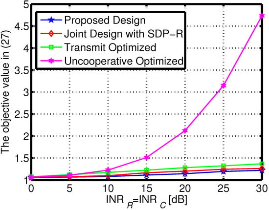
Figure 5.
The objective value under different of mutual interference.
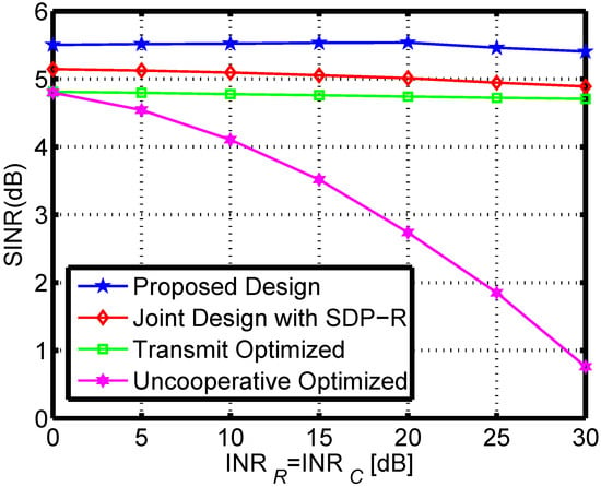
Figure 6.
The radar SINR under different of mutual interference.
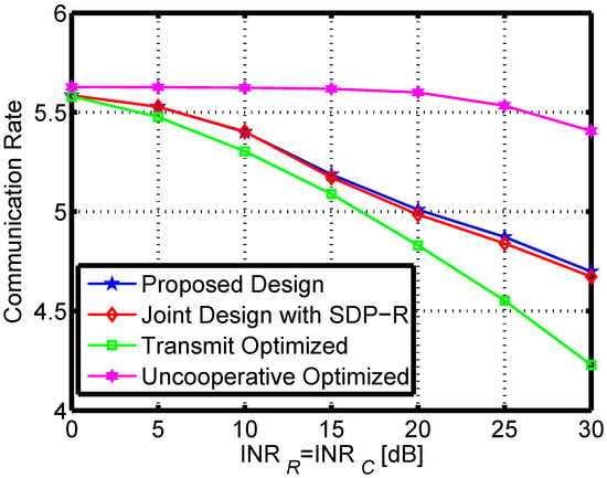
Figure 7.
The communication rate under different of mutual interference.
Moreover, Figure 8 depicts the Doppler-azimuth plane of radar CAF. In the scenario, the number of radar target is set as one and the target is located at with , the other parameters remain the same as Figure 4. For comparison, the concept of radar SINR optimization with communication rate constraint is used (see e.g., [46,52]). The communication rate is required to be greater than 4. It can be demonstrated that both systems have strong convergence qualities. Additionally, it can be noticed that the proposed design has more prominent peak values for the radar target and lower values at the clutter ridge and communication interference ranges, implying that the proposed formulation performs better. In effect, the formulation of radar optimization with communication constraint would lead to performance degradation due to the shrinkage operation for the set of lower bound of communication rate.
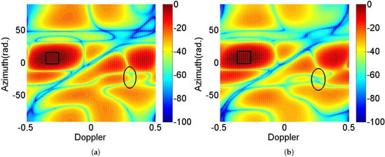
Figure 8.
Doppler-azimuth plane of CAF for iteration number for different formulations.
To further investigate the system performance in the environment of dynamic variation, the sensitiveness of the previous strategies is examined. In particular, assume that the estimated channel matrices are and , where and denote the channel estimation error matrices. In this exemplification study, is set to be 0.1. The other parameters remain unchanged. Figure 9 shows the objective value under different of mutual interference for channel mismatch. Combing the results in Figure 5, some degradations are observed, but the proposed design still effectively mitigates both the clutter and the mutual interference.
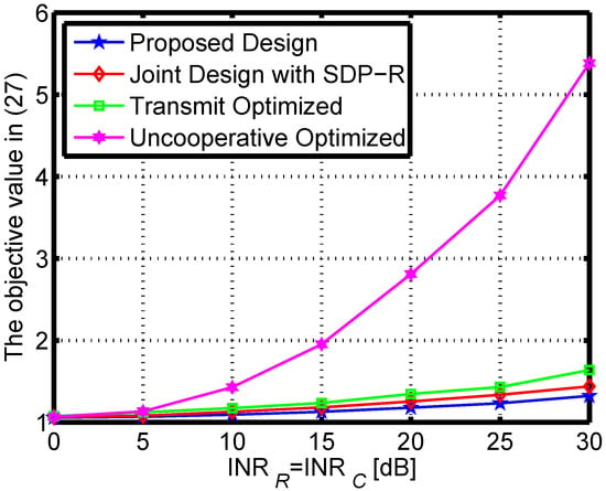
Figure 9.
The objective value under different of mutual interference for channel mismatch.
6. Conclusions
In this paper, we aim to jointly design the radar spatial-temporal transceiver and the communication spatial-temporal codebook in the spectrum coexistence system on moving platforms. Owing to the non-convexity of the original formulated problem, an alternate scheme is developed to optimize the designed DoFs based on the dual algorithm, the MVDR method and MM-ADMM. Analytical proofs have been provided for the algorithms’ convergences. Finally, the simulation results are shown to verify the performance of the proposed algorithm.
Author Contributions
Conceptualization, J.Q. and Z.L.; methodology, J.Q. and L.Z.; writing—original draft and formal analysis, Y.L., A.Z. and F.H.; writing—review and editing, Z.L. and Y.L. All authors have read and agreed to the published version of the manuscript.
Funding
This work was supported in part by the National Key R&D Program of China (Grant No. 2018YFE0202101, 2018YFE0202103), in part by the National Natural Science Foundation of China under Grants 62001064 and 62201388, and in part by the Chongqing Science and Technology Commission under Grant cstc2020jcyjmsxmX0705.
Data Availability Statement
Not applicable.
Acknowledgments
The authors would like to thank the reviewers and editor for their valuable comments and suggestions.
Conflicts of Interest
The authors declare no conflict of interest.
References
- De Matthaeis, P.; Oliva, R.; Soldo, Y.; Cruz-Pol, S. Spectrum Management and Its Importance for Microwave Remote Sensing [Technical Committees]. IEEE Geosci. Remote Sens. Mag. 2018, 6, 17–25. [Google Scholar] [CrossRef]
- Zheng, L.; Lops, M.; Eldar, Y.C.; Wang, X. Radar and communication coexistence: An overview: A review of recent methods. IEEE Signal Process. Mag. 2019, 36, 85–99. [Google Scholar] [CrossRef]
- Yang, J.; Aubry, A.; Maio, A.D.; Yu, X.; Cui, G. Design of Constant Modulus Discrete Phase Radar Waveforms Subject to Multi-Spectral Constraints. IEEE Signal Process. Lett. 2020, 27, 875–879. [Google Scholar] [CrossRef]
- Hassanien, A.; Amin, M.G.; Aboutanios, E.; Himed, B. Dual-function radar communication systems: A solution to the spectrum congestion problem. IEEE Signal Process. Mag. 2019, 36, 115–126. [Google Scholar] [CrossRef]
- Mishra, K.V.; Shankar, M.B.; Koivunen, V.; Ottersten, B.; Vorobyov, S.A. Toward millimeter-wave joint radar communications: A signal processing perspective. IEEE Signal Process. Mag. 2019, 36, 100–114. [Google Scholar] [CrossRef]
- Qian, J.; Venturino, L.; Lops, M.; Wang, X. Radar and Communication Spectral Coexistence in Range-Dependent Interference. IEEE Trans. Signal Process. 2021, 69, 5891–5906. [Google Scholar] [CrossRef]
- Wu, W.; Han, G.; Cao, Y.; Huang, Y.; Yeo, T.S. MIMO Waveform Design for Dual Functions of Radar and Communication With Space-Time Coding. IEEE J. Sel. Areas Commun. 2022, 40, 1906–1917. [Google Scholar] [CrossRef]
- Kafafy, M.; Ibrahim, A.S.; Ismail, M.H. Optimal Placement of Reconfigurable Intelligent Surfaces for Spectrum Coexistence With Radars. IEEE Trans. Veh. Technol. 2022, 71, 6574–6585. [Google Scholar] [CrossRef]
- Fang, Z.; Wang, W.; Wang, J.; Liu, B.; Tang, K.; Lou, L.; Heng, C.H.; Wang, C.; Zheng, Y. Integrated Wideband Chip-Scale RF Transceivers for Radar Sensing and UWB Communications: A Survey. IEEE Circuits Syst. Mag. 2022, 22, 40–76. [Google Scholar] [CrossRef]
- Hassanien, A.; Amin, M.G.; Aboutanios, E.; Himed, B. Cognitive radar waveform design and prototype for coexistence with communications. IEEE Sens. J. 2022, 22, 9787–9802. [Google Scholar]
- Cohen, D.; Mishra, K.V.; Eldar, Y.C. Spectrum Sharing Radar: Coexistence via Xampling. IEEE Trans. Aerosp. Electron. Syst. 2018, 54, 1279–1296. [Google Scholar] [CrossRef]
- Qian, J.; Wang, S.; Chen, Z.; Qian, G.; Fu, N. Robust Design for Spectral Sharing System Based on MI Maximization Under Direction Mismatch. IEEE Trans. Veh. Technol. 2022, 71, 6831–6836. [Google Scholar] [CrossRef]
- Marler, R.T.; Arora, J.S. The weighted sum method for multi-objective optimization: New insights. Struct. Multidiscipl. Optim. 2010, 41, 853–862. [Google Scholar] [CrossRef]
- Hao, Y.; Ni, Q.; Li, H.; Hou, S. On the energy and spectral efficiency tradeoff in massive MIMO-enabled HetNets with capacity-constrained backhaul links. IEEE Trans. Commun. 2017, 65, 4720–4733. [Google Scholar] [CrossRef]
- Cheng, Z.; Han, C.; Liao, B.; He, Z.; Li, J. Communication-aware waveform design for mimo radar with good transmit beampattern. IEEE Trans. Signal Process. 2018, 66, 5549–5562. [Google Scholar] [CrossRef]
- Chen, N.; Wei, P.; Gao, L.; Zhang, H. Beampattern synthesis and spectral compatibility based mimo radar waveform design. Digit. Signal Process. 2021, 118, 103211. [Google Scholar] [CrossRef]
- He, Q.; Wang, Z.; Hu, J.; Blum, R.S. Performance Gains From Cooperative MIMO Radar and MIMO Communication Systems. IEEE Signal Process. Lett. 2019, 26, 194–198. [Google Scholar] [CrossRef]
- Li, Z.; Shi, J.; Liu, W.; Pan, J.; Li, B. Robust Joint Design of Transmit Waveform and Receive Filter for MIMO-STAP Radar Under Target and Clutter Uncertainties. IEEE Trans. Veh. Technol. 2022, 71, 1156–1171. [Google Scholar] [CrossRef]
- Khawar, A.; Abdel-Hadi, A.; Clancy, T.C. Spectrum sharing between S-band radar and LTE cellular system: A spatial approach. In Proceedings of the 2014 IEEE International Symposium on Dynamic Spectrum Access Networks (DYSPAN), McLean, VA, USA, 1–4 April 2014; pp. 7–14. [Google Scholar]
- Shahriar, C.; Abdelhadi, A.; Clancy, T.C. Overlapped-MIMO radar waveform design for coexistence with communication systems. In Proceedings of the 2015 IEEE Wireless Communications and Networking Conference (WCNC), New Orleans, LA, USA, 9–12 March 2015; pp. 223–228. [Google Scholar]
- Bo, L.; Petropulu, A.P.; Trappe, W. Optimum Co-Design for Spectrum Sharing between Matrix Completion Based MIMO Radars and a MIMO Communication System. IEEE Trans. Signal Process. 2016, 64, 4562–4575. [Google Scholar]
- Qian, J.; Liu, Z.; Wang, K.; Fu, N.; Wang, J. Transmission Design for Radar and Communication Spectrum Sharing Enhancement. IEEE Trans. Veh. Technol. 2022. [Google Scholar] [CrossRef]
- Qian, J.; He, Z.; Huang, N.; Li, B. Transmit Designs for Spectral Coexistence of MIMO Radar and MIMO Communication System. IEEE Trans. Circuits Syst. II Express Briefs 2018, 65, 2072–2076. [Google Scholar] [CrossRef]
- Chen, P.; Zheng, L.; Wang, X.; Li, H.; Wu, L. Moving Target Detection Using Colocated MIMO Radar on Multiple Distributed Moving Platforms. IEEE Trans. Signal Process. 2017, 65, 4670–4683. [Google Scholar] [CrossRef]
- Bilik, I.; Longman, O.; Villeval, S.; Tabrikian, J. The Rise of Radar for Autonomous Vehicles: Signal Processing Solutions and Future Research Directions. IEEE Signal Process. Mag. 2019, 36, 20–31. [Google Scholar] [CrossRef]
- Wang, J. CFAR-Based Interference Mitigation for FMCW Automotive Radar Systems. IEEE Trans. Intell. Transp. Syst. 2022, 23, 12229–12238. [Google Scholar] [CrossRef]
- Xu, Z.; Yuan, M. An Interference Mitigation Technique for Automotive Millimeter Wave Radars in the Tunable Q-Factor Wavelet Transform Domain. IEEE Trans. Microw. Theory Tech. 2021, 69, 5270–5283. [Google Scholar] [CrossRef]
- Brooker, G.M. Mutual Interference of Millimeter-Wave Radar Systems. IEEE Trans. Electromagn. Compat. 2007, 49, 170–181. [Google Scholar] [CrossRef]
- Goppelt, M.; BlöCher, H.L.; Menzel, W. Automotive radar-investigation of mutual interference mechanisms. Adv. Radio Sci. 2010, 8, 55–60. [Google Scholar] [CrossRef]
- Liu, F.; Cui, Y.; Masouros, C.; Xu, J.; Han, T.X.; Eldar, Y.C.; Buzzi, S. Integrated Sensing and Communications: Toward Dual-Functional Wireless Networks for 6G and Beyond. IEEE J. Sel. Areas Commun. 2022, 40, 1728–1767. [Google Scholar] [CrossRef]
- Garcia, N.; Haimovich, A.M.; Lops, M.; Lops, M. Resource Allocation in MIMO Radar With Multiple Targets for Non-Coherent Localization. IEEE Trans. Signal Process. 2014, 62, 2656–2666. [Google Scholar] [CrossRef]
- Yu, X.; Alhujaili, K.; Cui, G.; Monga, V. MIMO Radar Waveform Design in the Presence of Multiple Targets and Practical Constraints. IEEE Trans. Signal Process. 2020, 68, 1974–1989. [Google Scholar] [CrossRef]
- Xu, Z.; Xue, S.; Wang, Y. Incoherent Interference Detection and Mitigation for Millimeter-Wave FMCW Radars. Remote Sens. 2022, 14, 4817. [Google Scholar] [CrossRef]
- Wang, J.; Aubry, P.; Yarovoy, A. 3-D Short-Range Imaging With Irregular MIMO Arrays Using NUFFT-Based Range Migration Algorithm. IEEE Trans. Geosci. Remote Sens. 2020, 58, 4730–4742. [Google Scholar] [CrossRef]
- Zhang, R.; Liang, Y.C.; Cui, S. Dynamic resource allocation in cognitive radio networks. IEEE Signal Process. Mag. 2010, 27, 102–114. [Google Scholar] [CrossRef]
- Karbasi, S.M.; Aubry, A.; Carotenuto, V.; Naghsh, M.M.; Bastani, M.H. Knowledge-based design of space-time transmit code and receive filter for a multiple-input-multiple-output radar in signal-dependent interference. IET Radar Sonar Navig. 2015, 9, 1124–1135. [Google Scholar] [CrossRef]
- Aubry, A.; DeMaio, A.; Farina, A.; Wicks, M. Knowledge-Aided (Potentially Cognitive) Transmit Signal and Receive Filter Design in Signal-Dependent Clutter. IEEE Trans. Aerosp. Electron. Syst. 2013, 49, 93–117. [Google Scholar] [CrossRef]
- Gini, F.; Maio, A.D.; Patton, L. Waveform Design and Diversity for Advanced Radar Systems; The Institution of Engineering and Technology: London, UK, 2012. [Google Scholar]
- Zeng, Y.; Zhang, R. Millimeter Wave MIMO With Lens Antenna Array: A New Path Division Multiplexing Paradigm. IEEE Trans. Commun. 2015, 64, 1557–1571. [Google Scholar] [CrossRef]
- Zhang, X.; Li, H.; Liu, J.; Himed, B. Joint delay and doppler estimation for passive sensing with direct-path interference. IEEE Trans. Signal Process. 2016, 64, 630–640. [Google Scholar] [CrossRef]
- Filo, M.; Hossain, A.; Biswas, A.R.; Piesiewicz, R. Cognitive pilot channel: Enabler for radio systems coexistence. In Proceedings of the 2009 Second International Workshop on Cognitive Radio and Advanced Spectrum Management, Aalborg, Denmark, 18–20 May 2009; pp. 17–23. [Google Scholar]
- Gottumukkala, V.K.V.; Minn, H. Capacity Analysis and Pilot-Data Power Allocation for MIMO-OFDM With Transmitter and Receiver IQ Imbalances and Residual Carrier Frequency Offset. IEEE Trans. Veh. Technol. 2012, 61, 553–565. [Google Scholar] [CrossRef]
- Maio, A.D.; Nicola, S.D.; Huang, Y.; Luo, Z.Q. Design of Phase Codes for Radar Performance Optimization With a Similarity Constraint. IEEE Trans. Signal Process. 2009, 57, 610–621. [Google Scholar] [CrossRef]
- Trees, H.L.V. Optimum Array Processing, Part IV of Detection, Estimation, and Modulation Theory; Wiley: Hoboken, NJ, USA, 2002. [Google Scholar]
- Boyd, S.; Vandenberghe, L. Convex Optimization; Cambridge University Press: Cambridge, UK, 2004. [Google Scholar]
- Qian, J.; Lops, M.; Zheng, L.; Wang, X.; He, Z. Joint System Design for Co-existence of MIMO Radar and MIMO Communication. IEEE Trans. Signal Process. 2018, 66, 3504–3519. [Google Scholar] [CrossRef]
- Ghadimi, E.; Teixeira, A.; Shames, I.; Johansson, M. Optimal Parameter Selection for the Alternating Direction Method of Multipliers (ADMM): Quadratic Problems. IEEE Trans. Autom. Control 2015, 60, 644–658. [Google Scholar] [CrossRef]
- Yeh, J. Real Analysis: Theory of Measure and Integration; World Scientific: Singapore, 2006. [Google Scholar]
- Lu, J.; Liu, F.; Sun, J.; Liu, Q.; Miao, Y. Joint Estimation of Target Parameters and System Deviations in MIMO Radar With Widely Separated Antennas on Moving Platforms. IEEE Trans. Aerosp. Electron. Syst. 2021, 57, 3015–3028. [Google Scholar] [CrossRef]
- Boyd, S.; Parikh, N.; Chu, E.; Peleato, B.; Eckstein, J. Distributed optimization and statistical learning via the alternating direction method of multipliers. Found. Trends® Mach. Learn. 2011, 3, 1–122. [Google Scholar]
- Cui, G.; Li, H.; Rangaswamy, M. MIMO Radar Waveform Design With Constant Modulus and Similarity Constraints. IEEE Trans. Signal Process. 2014, 62, 343–353. [Google Scholar] [CrossRef]
- Qian, J.; Lu, M.; Huang, N. Radar and Communication Co-Existence Design Based on Mutual Information Optimization. IEEE Trans. Circuits Syst. II Express Briefs 2020, 67, 3577–3581. [Google Scholar] [CrossRef]
Publisher’s Note: MDPI stays neutral with regard to jurisdictional claims in published maps and institutional affiliations. |
© 2022 by the authors. Licensee MDPI, Basel, Switzerland. This article is an open access article distributed under the terms and conditions of the Creative Commons Attribution (CC BY) license (https://creativecommons.org/licenses/by/4.0/).
