1. Introduction
Ground penetrating radar (GPR) is widely used in archaeological, environmental, hydrological and engineering surveys to detect subsurface structures [
1,
2,
3]. The most widely used GPR detection method is a non-destructive survey method in which the transmitters and receivers are placed on the ground at the same time. This paper focuses on the cross-hole GPR method (typically 20–250 MHz), where the transmitters and receivers are placed in two nearby boreholes, respectively. High-resolution tomographic images of the permittivity and conductivity between the two boreholes are provided by inversion of the direct wave information propagating in the interval between the two boreholes. The vertical depth of this detection method depends on the depth of the borehole, and it can penetrate the regolith to detect the deep formation. Its lateral detection range can be greater than 100 m in crystalline rocks, while in relatively conductive rocks (200–300 Ω·m), the detection range can reach 10–20 m. In addition to the detection range, the radar can perform multiple repeated detections at key locations, using stack averaging to improve the signal-to-noise ratio.
Traditional cross-hole GPR tomography methods are generally based on ray theory, such as the ray tracing method based on the first-arrival traveltime [
4,
5,
6,
7,
8] and the attenuation tomography based on the maximum amplitude (centroid frequency downshift method) [
9], which can invert the permittivity and conductivity, respectively. The traveltime tomographic inversion method is theoretically more mature and can provide reliable velocity inversion results. However, attenuation imaging is still theoretically inadequate and can only reflect the relative conductivity distribution between the target body and the formation. In addition, the tomographic inversion method based on ray theory utilizes part of the signal information, so that the tomographic method can only image anomalies larger than the dominant wavelength of the signal. The resolution is around the width of the first Fresnel zone [
10,
11]. Waveform inversion can utilize complete waveform information. Under the most ideal conditions, its resolution can reach the sub-wavelength level [
12,
13] (one-half to one-third wavelength).
The full waveform inversion method has achieved a series of achievements in the field of seismic first, and then gradually developed in the field of ground penetrating radar. In terms of seismic, Tarantola et al. [
14,
15,
16] proposed a time-domain full waveform inversion based on generalized least squares inversion theory. The gradient direction is constructed by using the cross-correlation of the forward wavefield and the residual backpropagation wavefield, thus avoiding the direct calculation of the Fréchet derivative. Subsequently, Pratt et al. [
17,
18] extended it to the frequency domain and formed the frequency domain waveform inversion to improve the computational efficiency. For GPR, Kuroda et al. [
19] and Meles et al. [
20] used the GPR full waveform inversion method, which is similar to the seismic waveform inversion method, to image the cross-hole GPR data and achieved good results. Kuroda et al. only considered the permittivity, while Ernst et al. [
21,
22] considered both the permittivity and the conductivity through the cascade update method. The basic idea of the latter is to invert the permittivity with a fixed conductivity, and vice versa. The two methods have in common that they are both scalar in nature. The waveform inversion method proposed by Meles considers the vector nature of electrical parameters and allows the permittivity and conductivity to be updated simultaneously during the inversion.
Although waveform inversion methods can provide high-resolution images of subsurface medium distribution, they have a serious drawback in that they are highly dependent on the initial model. This is due to the huge amount of data in the inversion and the highly nonlinear nature of waveform inversion. Therefore, gradient-like optimization algorithms are often used to achieve convergence of the inversion process. Gradient algorithms are prone to fall into local minima. To avoid this situation, FWI requires an accurate initial model to ensure convergence. Bunks et al. [
23] proposed a time-domain multi-scale waveform inversion strategy in 1995, the principle of which is that low-frequency signals are not sensitive to local minima. The full waveform inversion of low-frequency data is easier to converge to the global minimum, so the dependence on the initial model is low. In the initial stage of the inversion, using low-frequency data to obtain relatively accurate smooth background velocity and large-scale structure, and then using high-frequency data to describe the fine structure can improve the stability of the inversion and obtain better inversion results. Moreover, the multi-scale inversion strategy is also applicable to the GPR domain [
24]. To solve the problems existing in the traditional FWI inversion process, a series of waveform inversion methods based on special objective functions are proposed [
25,
26,
27,
28,
29,
30,
31]. Subsequently, the partial information waveform inversion method based on special objective function was successfully developed in the field of GPR [
32,
33,
34].
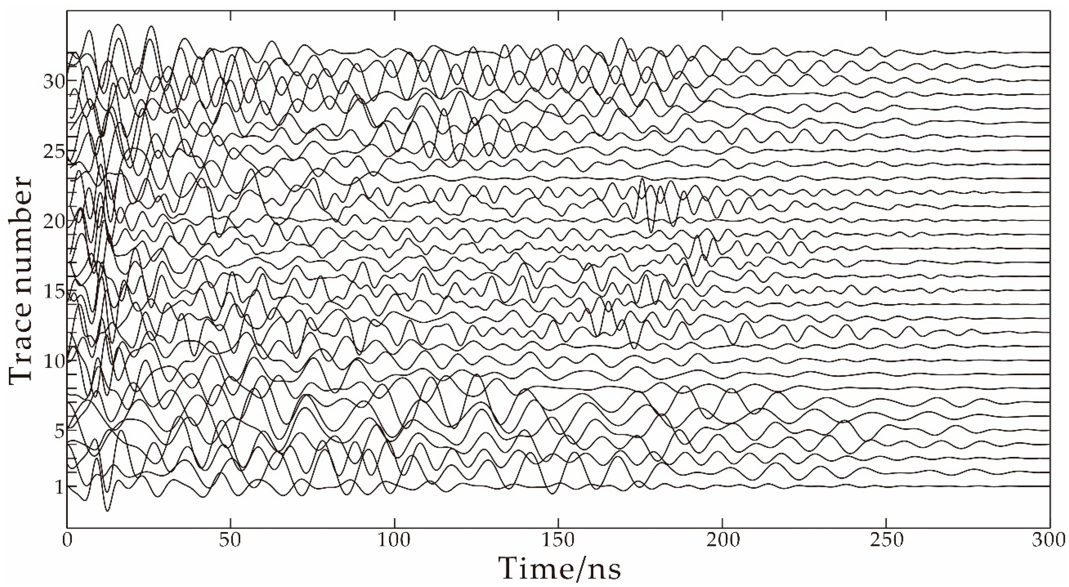
Another key issue for GPR practical data processing is source wavelet estimation. The usual practice is to reverse the real data to obtain the source wavelet waveform required for forward modeling. Edemsky et al. [
35] developed a deconvolution technique for GPR. An inverse problem of antenna current reconstruction from the measured waveform of direct surface wave is solved analytically. Belina et al. [
36] initially proposed a deconvolution technique, which calculates the source wavelet before inversion. If convergence is difficult during the inversion process, the source wavelet can be updated. However, for the real GPR data, we found that the source wavelet estimation method needs to process the data of each trace, and the amount of real GPR data is large. This process will reduce the efficiency of the inversion, and it needs to be updated repeatedly during the inversion. This process needs to be performed manually, which is time-consuming and requires a professional operation. On the other hand, when estimating the source wavelets of the real data, it is found that the estimated waveforms of each trace are not consistent. The overall shape, amplitude and phase are inconsistent, and the differences are huge. The reason for this phenomenon is related to the environment during data collection and the instrument itself. This problem is unavoidable and will hinder the source wavelet estimation, which in turn affects the waveform inversion. Choi et al. and Lee et al. [
26,
27] proposed a source-independent FWI in the time domain. They convolved the simulated data and observation data with the reference trace in the time domain to eliminate the influence of wavelets and successfully applied them to seismic data inversion.
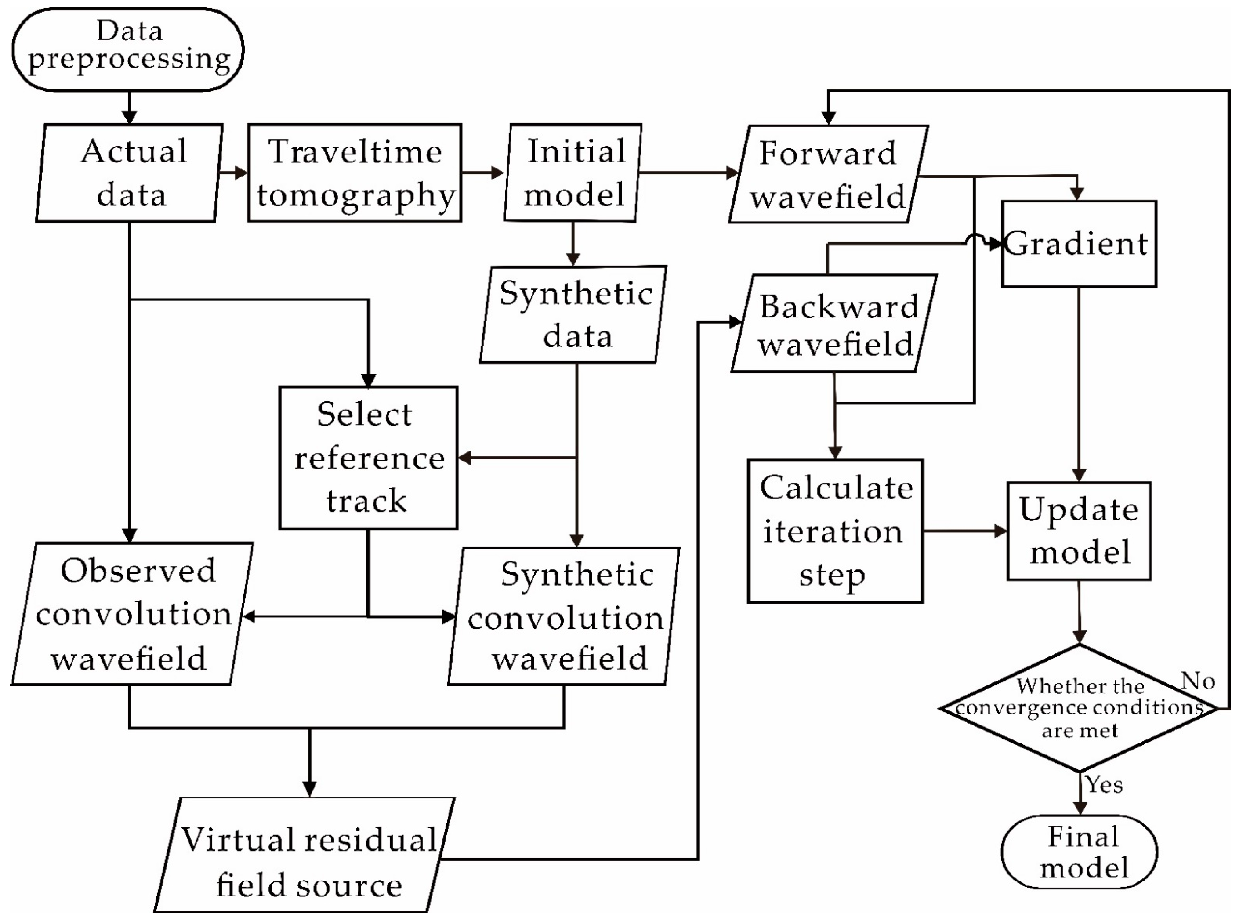
In this study, we use a source-independent waveform inversion method based on the envelope objective function (SIEWI) to invert cross-hole GPR data in the time domain. SIEWI has a successful application experience in the seismic field [
37]. In this paper, the gradient and step size equations of SIEWI are re-derived for GPR in the time domain, and the dual-parameter simultaneous inversion of permittivity and conductivity is achieved. First, we convolve the real data with a reference trace from the forward data. Similarly, we convolve the forward data and a reference trace from the real data, and simultaneously, take the envelope of the two sets of convolution results to establish a new objective function. In theory, the new convoluted wavefield shares the same source wavelet, regardless of the excitation pulse used in the forward process. Another important feature of the new objective function is that the source wavelet used in the forward wavefield plays a filtering role on the convolutional wavefield. The envelope transform can effectively restore the low-frequency information of the data and can suppress the local minimum, which further guarantees the effectiveness of the method. For the forward modeling in the inversion processing, we solve Maxwell’s equation for the transverse electric (TE) mode by using the 2D finite-difference time-domain method (FDTD) with the convolutional perfected marched layer (CPML) absorbing boundary condition [
38]. This paper applies this method to synthetic data and real data to test its effectiveness.
2. Methods
2.1. Derivation of the Objective Function
The objective function for conventional time-domain full waveform inversion is the
l2 norm between the real and forward data.
In Equation (1),
E(
ε,
σ) and
Eobs are synthesized data and real data, respectively, and the value of the objective function is the sum of the residuals on all transmitters (indicated by
i), receivers (indicated by
j) and the observation time (indicated by
τ). The electric field of the ground penetrating radar can be considered as the convolution of the source wavelet and
Green’s function
g, so the objective function can be rewritten as follows:
where
for corresponds to the synthesized data
E(
ε,
σ);
obs corresponds to the observed data
Eobs; * is the convolution operator. Before inverting the real data, a very important step is to estimate the source wavelet
sobs of the real data. Since there may be problems with real data quality, the source wavelets estimated from each signal are often inconsistent. There are unavoidable differences in amplitude and phase between each wavelet. For data with poor signal-to-noise ratio, this difference will be very large. This increases the difficulty of estimating the source wavelet, so the process of estimating the source wavelet often consumes a lot of time and has potential errors.
In order to avoid the above problems, this paper adopts a waveform inversion method that does not depend on the source wavelet. The objective function of this method is:
where
k is the reference trace selected according to the situation. Rewrite Equation (3) into a convolution form, such as Equation (2):
Equation (4) is similar to Equation (2), and it can be seen that the two items in the objective function have the same source wavelet. Therefore, no matter what kind of source wavelets are provided for forwarding modeling in inversion, the purpose of waveform inversion can be achieved. The full waveform inversion based on the new objective function Equation (3) does not depend on the accurate source wavelet. For traditional FWI, the inaccurate source wavelet has a great influence on the inversion.
In this paper, the objective function of SIEWI is modified using the envelope algorithm to suppress local minima, further guaranteeing the effectiveness of the method. The objective function is given in Equation (5):
where
Ec is the envelope of the simulated convolution wavefield, and
is the envelope of the observed convolution wavefield. Their corresponding expressions are:
H denotes the Hilbert transform operator. Since the new objective function is composed of two envelopes in Equation (3), the waveform inversion method based on Equation (5) still uses the same source wavelet ().
2.2. Gradient
The gradient is obtained by deriving the objective function (5) with the model parameter
p:
where
Putting Equations (9)–(11) into Equation (8) and sorting out:
For the convenience of equation derivation, the above equation is divided into four parts and the equations are:
In the above Equation (13), the product of the first two items is represented by
After sorting, Equation (13) can be written in integral form:
Let
; then
can be rewritten as:
is the cross-correlation between the residual and the real data reference trace, which represents the backward residual field source of Equation (13):
Equation (19) is a simplified form of Equation (18). It can be seen that Equation (19) is the result of the dot multiplication between the first-order partial derivative (
) and the cross-correlation residual (
) of the electric field to the model parameters, which is similar to the gradient equation for waveform inversion under the traditional objective function. In Equation (19),
is the backward residual field source derived in Equation (13). After rearranging, Equation (19) is rewritten as:
Since the transmitters represented by the virtual source vector
are forward, and the receivers represented by
Green’s function
are reverse in time series, the subscripts of the two are not the same, and the order is opposite to correspond to the time series. Set
; then
. Equation (21) can be rewritten as:
represents the backward propagation field with the opposite time series, and Equation (22) is the zero-phase convolution of the virtual source and the backward propagation field. According to Equation (22), the gradient expressions of permittivity and conductivity are given in this paper:
in which
can be interpreted as a backward propagating vector field in the same medium, where:
Then, Equations (14)–(16) are derived in the same way as formula (13). Then, we can obtain the remaining three components of the backward residual field source corresponding to Equation (12), which are:
where
and
denote the adjoint sources at any detection point
j;
and
denote the adjoint sources at the reference trace
k. Subsequently, we merge
and
to obtain the backward residual field source
;
and
merge to obtain the backward residual field source
. The equations of
and
are:
In Equations (28) and (29), denotes the cross-correlation operator. What needs to be noticed is the changes in the subscripts of Equations (28) and (29). The reference trace in is selected from the observation data; the reference trace needs to be selected according to the actual situation before inversion. Usually, the reference trace is the one closer to the transmitter or replaced by averaging traces. The reference trace in is selected from synthetic data. During the inversion, synthetic data need to be superimposed; the final superimposed data are used as one trace to perform a cross-correlation operation with the actual data.
Finally, we give the gradient of permittivity and conductivity:
where
T is the backward propagation field, and it can be seen that and are jointly used as the residual field source.
2.3. Step Calculation
In the iteration, the conjugate gradient method is used to update the permittivity and conductivity at the same time [
39]:
where
and
are the gradient directions of the permittivity and conductivity during the kth iteration, respectively.
and
are the iteration steps corresponding to gradients
and
, respectively. The calculation equation for conjugate gradient is:
When
k = 1, the gradients of the two are
and
, respectively. Introducing the conjugate gradients
and
simultaneously updating the permittivity and conductivity of the model at the same time, we can give the error calculation method at the
k + 1 iteration:
This method finds the optimal step size
ζ, that is, searches for the minimum value of the objective function along the gradient direction, where ε and σ denote permittivity and conductivity, respectively.
is the gradient of the
k-th iteration. Since the above three are fixed, the minimum value can be reached by setting the first derivative to zero:
According to the optimal step length equation of the conventional GPR full waveform inversion method [
40], we give the best step length equation suitable for SIEWI to update the permittivity and conductivity at the same time:
with
In the equation, env denotes the envelope transformation of the convolution wavefield. κε and κσ are small stability factors specified according to the magnitude of the gradient extreme value during the step calculation. When the stability factor is within a reasonable order of magnitude, the iteration can guarantee stability, and it changes continuously as the iteration progresses.
5. Discussion
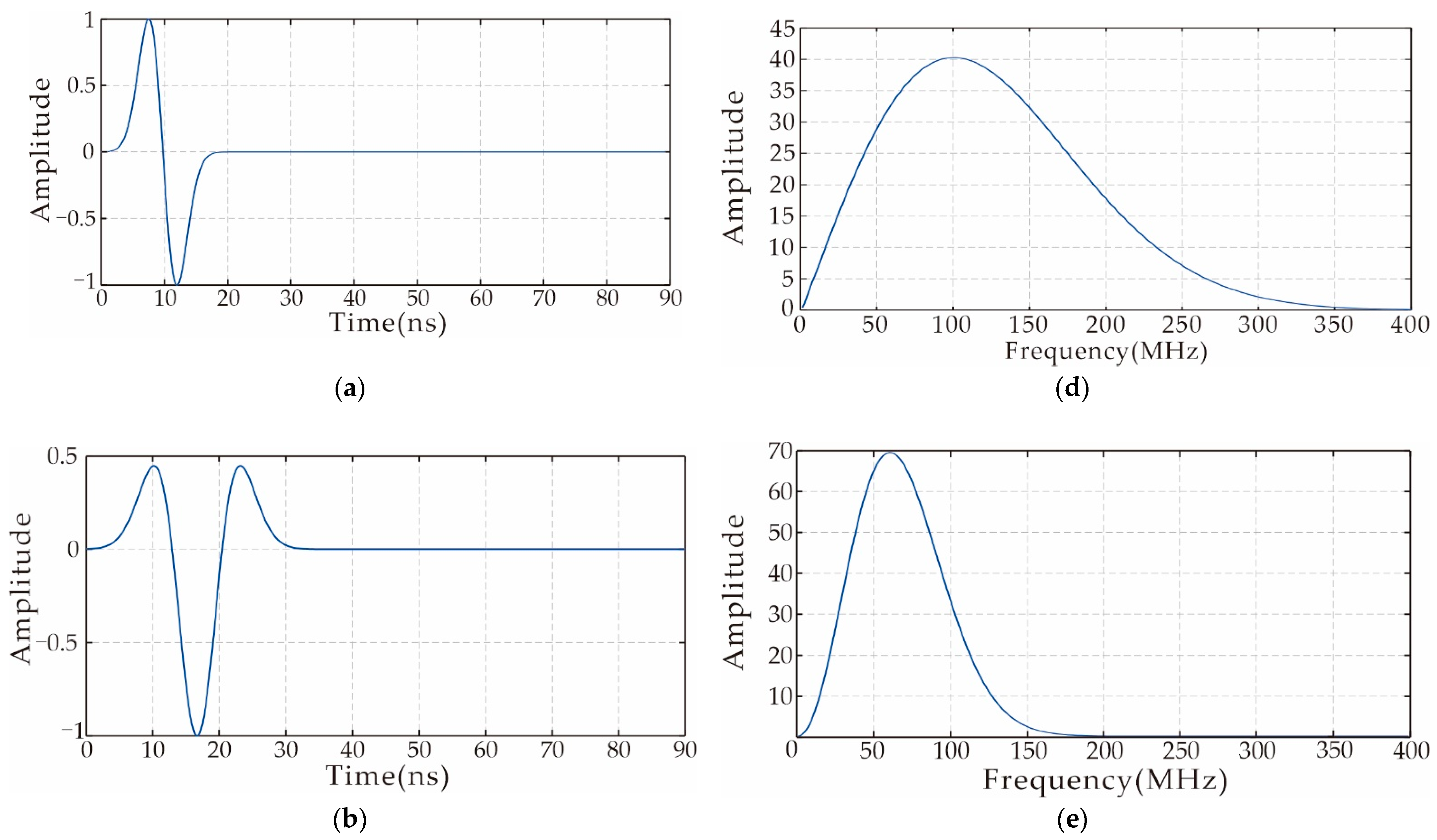
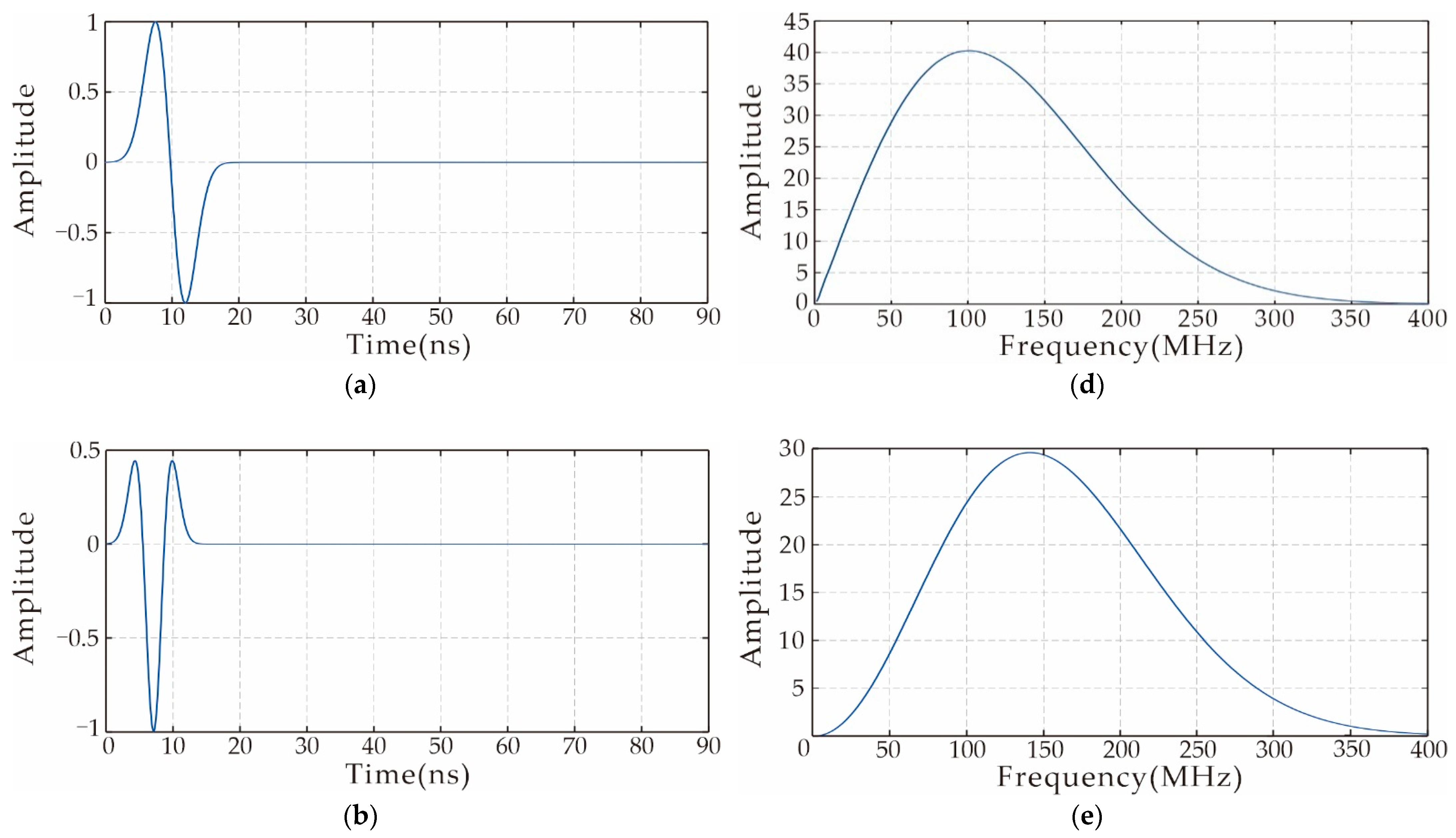
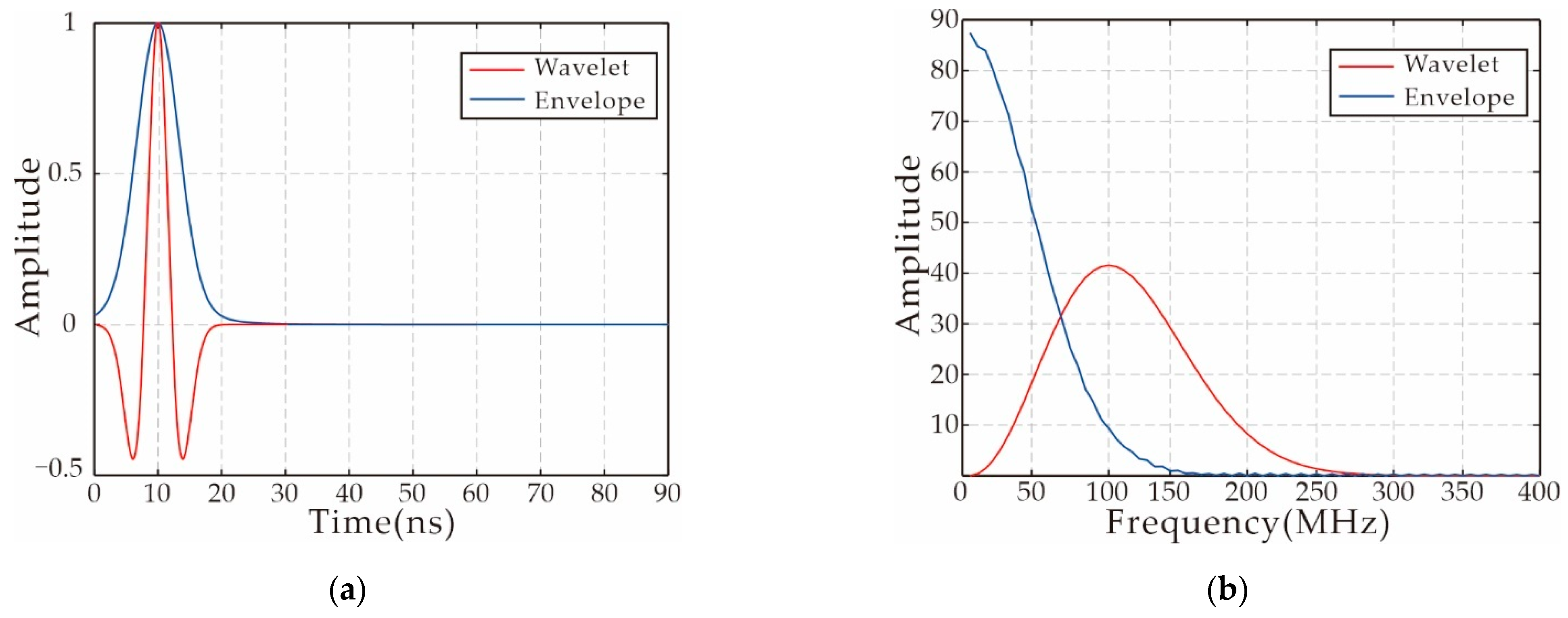
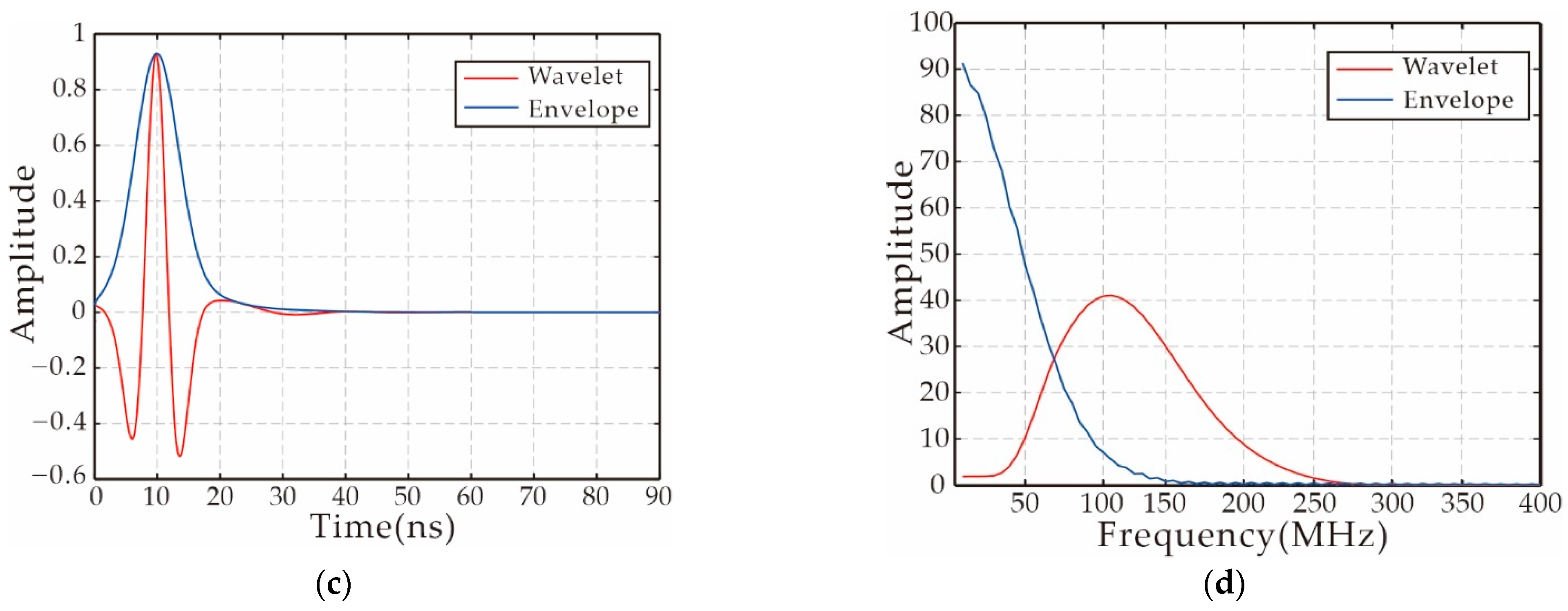
SIEWI is a waveform inversion method that does not rely on source wavelet in the inversion process. Because of this feature, it can ignore the important step of source wavelet estimation in the actual data inversion. In this paper, the SIEWI method is used to realize the inversion of synthetic data and actual data of cross-hole GPR. Compared with other waveform inversion methods, the biggest difference in SIEWI is that it does not need to estimate source wavelet at all. In actual data processing, source wavelet estimation is time-consuming and inaccurate. SIEWI avoids these problems. In order to make this method more suitable for inversion of cross-hole GPR in the time domain, we designed a multi-scale inversion strategy based on convolution. The envelope objective function is established by transforming the convolution wavefield, which can effectively solve the lack of low-frequency information caused by data acquisition and convolution operations. At the same time, the convolution and cross-correlation operations are nonlinear mathematical operations, which will increase the nonlinearity of the inversion. The envelope objective function can effectively suppress the nonlinear problem, avoid falling into a local minimum and make the inversion more stable. The convolution spectrum analysis proves that the frequency range of the residual field source can be controlled indirectly by changing the source wavelet frequency, and then a multi-scale inversion strategy suitable for SIEWI is established.
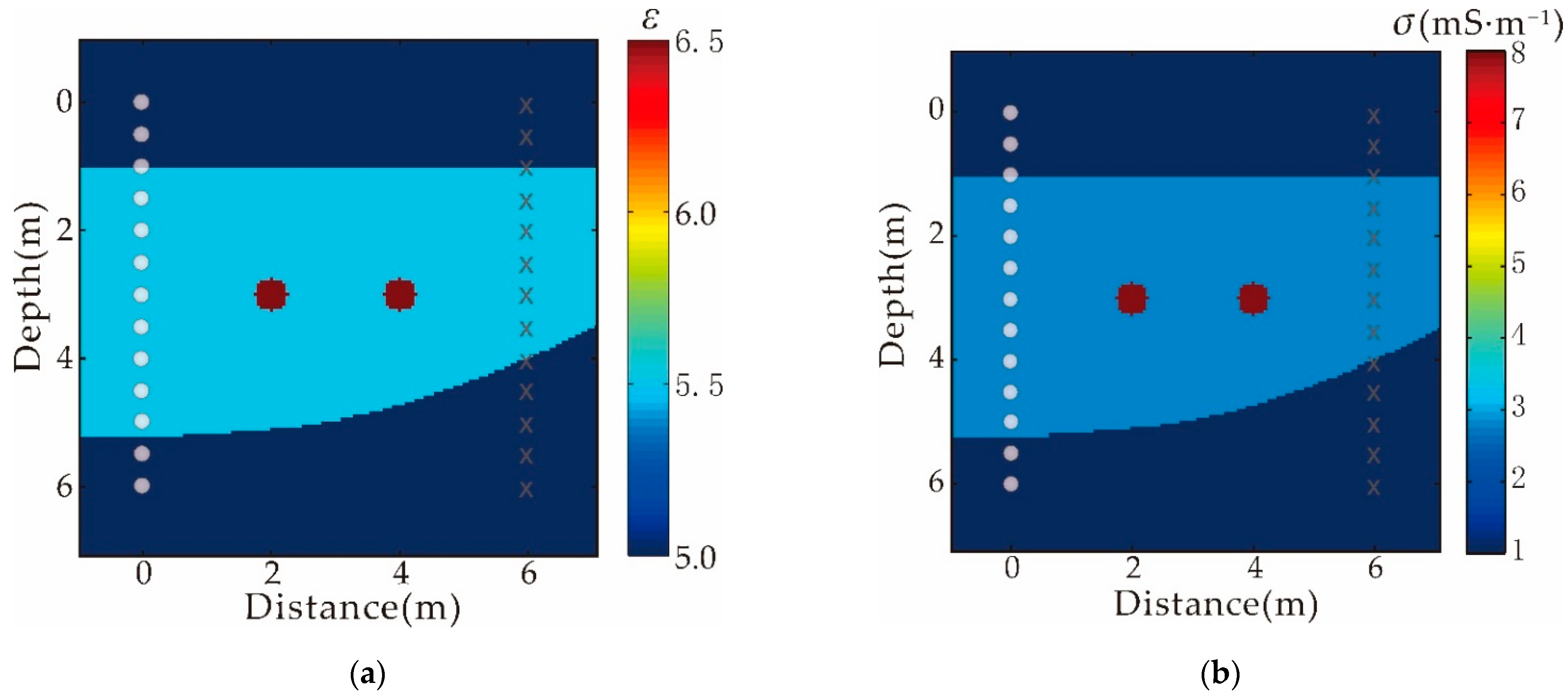
In this paper, SIEWI is used for the inversion of cross-hole ground penetrating radar data. The inversion capability of this method is verified by synthetic data, and it is proved that the accurate restoration of the cross-hole model can still be achieved when the source wavelet is wrong and the traditional FWI inversion cannot work. Compared with traditional FWI, SIEWI eliminates the complicated step of wavelet estimation which requires multiple manual interventions during the real data inversion. The efficiency of inversion is greatly improved. At the same time, it also avoids the serious impact on the inversion results if the source wavelet estimation is wrong. Comparing the inversion results of FWI and SIEWI, it shows that SIEWI has the ability to restore more stratigraphic information, especially to further verify the strata with doubts in the FWI results. The information is valuable for the prediction of unknown underground geological structures.
6. Conclusions
We successfully implemented a waveform inversion method that does not require source wavelets and applied it to cross-hole GPR data. For SIEWI, we derive in detail the gradient and step size required for the inversion. In the inversion, the characteristics of the convolution transform are fully utilized, and the multi-scale SIEWI strategy is established. In this paper, the tomographic inversion results are used as the initial model, and synthetic data and real data are inverted using SIEWI and FWI. Through synthetic data verification, SIEWI can realize the inversion of GPR cross-hole data, and it is proved that when the source wavelet is wrong and FWI cannot work, SIEWI can still work normally. In terms of actual data, the inversion results of SIEWI and FWI are relatively close on the whole, but there are some differences, which are mainly reflected in the conductivity results. There is horizon information in the SIEWI conductivity inversion results that was not obvious in the FWI results, and this horizon information has a certain reference value. In addition, the FWI inversion result is the best result obtained after multiple debugging, and in the entire iterative process, the source wavelet re-estimation is performed every ten iterations, requiring multiple manual interventions. However, SIEWI does not require manual intervention at all, and the inversion efficiency is greatly improved.
