Abstract
The aerodynamic thermal ionization affects the re-entry target, and the surface will form a ‘plasma sheath (PSh).’ The PSh with fluid characteristics will produce relative motion with the re-entry target. In the radar detection of the re-entry target, the relative motion characteristics cause the echo signal to couple different intra-pulse Doppler frequency components, forming a ‘false target’ on the one-dimensional range profile. In addition, the flight velocity of the re-entry target is exceptionally high (usually greater than 10 Mach), and there will be a severe phenomenon of migration through range cells (MTRC) during the detection period, which will make the coherent integration of the multi-period radar echo signal invalid and further affect the reliable detection of the re-entry target. Aiming at the ‘false target phenomenon’ and MTRC phenomenon in the process of re-entry target detection, this paper proposes an improved keystone algorithm. Based on the traditional keystone algorithm, a reliable, coherent integration method for radar echo of the plasma-sheath-covered target is proposed by modifying the scale transformation factor and constructing the Doppler frequency compensation function. It can effectively compensate the intra-pulse Doppler frequency and inter-pulse Doppler frequency to improve the energy gain of the real target and lay a theoretical foundation for the reliable detection of the plasma-sheath-covered target.
1. Introduction
When various re-entry targets are moving in nearby space at hypersonic velocity, the high-velocity incoming flow in the stagnation area of the target generates a high temperature after passing through the shock layer, and a large number of air molecules are dissociated and ionized. The ionized products move relative to the target and flow from the stagnation point area to the tail end area to form a ‘plasma sheath (PSh).’ PSh is a complex electromagnetic (EM) medium that produces a series of EM interference, such as power modulation and phase disturbance to EM waves [1]. In addition, PSh with fluid characteristics will generate reflected radar signals [2,3,4,5,6], increasing the echo signal component.
In the early research, Close et al. conducted radar observations of the sporadic Leo meteor shower (a type of re-entry target), analyzed the RCS of meteors in different frequency bands and proved that the appearance of the PSh caused the signal component in the echo to increase [1]. Figure 1 shows the radar detection results of meteors under two frequency conditions. The left diagonal is the head echo, considered to be the reflection signal of the head meteor plasma, and the right diffuse reflection signal is the non-specular trail, which is considered the reflection signal formed by the plasma. At present, referring to the radar detection results of meteor plasma, the re-entry target should have at least two reflected signals under the influence of the PSh. Zhang Xi et al. established a broadband echo model of the flow field distribution in the PSh based on the transmission/reflection process of EM waves in the PSh, and initially analyzed the ‘false target’ phenomenon caused by the PSh [7]. On this basis, the author of this article has carried out research on the Doppler frequency compensation method of the single-period echo signal. By increasing the energy gain of the real target, the target detection of the single-period echo signal is realized [8]. Although the current research has made some progress, the research on the processing of multi-period radar echoes of the PSh-covered target is still in its infancy.

Figure 1.
Radar detection results of meteor plasma: (a) very high frequency; (b) ultra high frequency.
Due to the limited bandwidth of the radar transmitting signal (the bandwidth is inversely proportional to the range resolution unit), the high moving velocity of the target causes the migration through range cells (MTRC) phenomenon. The research on the solutions to the MTRC phenomenon caused by the high-velocity movement is relatively mature, such as the maximum likelihood method [9], the coherent Radon transform [10], and the algorithm based on the Keystone transform (KT) [11,12,13,14]. However, the above methods are mainly aimed at rigid targets. The generation of the PSh changes the characteristics of the targets, changing from a traditional rigid target to a composite target with a fluid-covered rigid body, which makes the traditional method inapplicable. Therefore, there is still no effective detection method to detect the PSh-covered target.
Given the above situation, this paper simulates the radar echo signal of the PSh-covered target and analyzes the relationship between the inter-pulse Doppler frequency (IrD-frequency) and the intra-pulse Doppler frequency (IaD-frequency) in detail from the theoretical perspective. The IaD-frequency of echo signal coupling is extracted by fractional Fourier transform. The scale transformation factor is improved by using the IaD-frequency, and the IrD-frequency compensation function is constructed by the approximation criterion of the IaD-frequency and the IrD-frequency. Based on the improved scale transformation factor and the IrD-frequency compensation function, the traditional keystone algorithm is improved to eliminate the MTRC phenomenon, and the ‘false target’ phenomenon of the multi-period echo signal energy gain of the real target is significantly improved. Finally, the feasibility of the proposed algorithm is verified through theoretical deduction, and the algorithm’s effectiveness is further verified through simulation.
2. Detection Method of PSh-Covered Target Based on Improved Keystone Algorithm
2.1. Echo Model of the PSh-Covered Target
When the target passes through the Earth’s atmosphere, its surface is covered with a PSh, as shown in Figure 2.
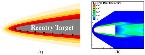
Figure 2.
(a) PSh-covered target; (b) electron density calculation results.
In Figure 2, the gray part denotes the target, and the colored part denotes the PSh, and the black dots denote different reference points on the surface of the target.
Due to the fluid characteristics of the PSh, the far-field plane wave has different electromagnetic scattering characteristics and relative motion characteristics at different positions of the PSh, as shown in Figure 3.
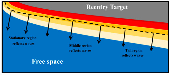
Figure 3.
Local reflection characteristics of PSh-covered targets.
By referring to [15], the IrD-frequency and reflection coefficient of each reference position under the PSh can be obtained, and the echo signal of the PSh-covered target can be obtained.
The following table shows the calculation process for determining the reflection coefficient and Doppler frequency of the n-th point:
In the table above, c is the velocity of light; fd(n) and fp(n,zm) respectively represent the IaD-frequency of the PSh at the n-th reference point and characteristic frequency of the PSh at the n-th reference point; fc represents the carrier frequency of RF signal; A(n) B(n) C(n) and D(n) represent the transmission parameters of the PSh at the n-th reference point; Z0 represents the vacuum’s impedance; and Zm+1 represents the impedance of the m-th layer at the reference point.
According to the reflection coefficient and Doppler frequency equation in Table 1, the reflection coefficient and Doppler modulation frequency at different positions of the target are calculated, and the radar echo model of the PSh-covered target is established. The echo signal Rpla(, tq) of the q-th period of the n-th reference point is as follows [15]:
where is the fast time, τ0 represents the initial time delay, τv,q is the time delay which is caused by the range change induced by the q-th period (q = 1, 2, …, Q), which is expressed as follows:
where Vr represents the radial velocity of the target rigid body. φ0(n) in Equation (1) represents the phase term containing the IaD-frequency, which is expressed explicitly as follows:
p() represents the complex envelope of the linear frequency modulation pulse signal, which can be specifically expressed as follows [16,17]:
where k and Tp are the radar signal’s modulation frequency and pulse width, respectively.

Table 1.
Reflection coefficient and IaD-frequency calculation process.
According to the reference [12], the time–domain waveform of the radar echo is severely distorted, and the disturbance within the pulse is serious. Through conducting pulse compression and frequency mixing operation on the echo signal expression of Equation (1), the pulse compression result ypla(, q) of the echo signal is as follows:
In the above Equation (5), R0 is the initial range of the target, and fd(Vr) represents the IrD-frequency (IrD-frequency is determined by the target’s radial velocity). φ1(n) represents the phase term in the pulse compression result, which is expressed explicitly as follows:
It can be seen from Equation (5) that the Sinc(.) function in the echo signal represents the target position on the one-dimension range profile after being pulse compressed, and the Sinc(.) function peak is affected by the IaD-frequency and the IrD-frequency.
Equation (5) can be further rewritten as:
It can be seen from the above equation that the peak position of the one-dimensional range profile of the echo signal is affected by both the pulse width and the bandwidth. When the pulse width increases, the peak interval increases; when the pulse width decreases, the peak interval decreases. The IrD-frequency affects the phenomenon of MTRC, thereby further causing coherent accumulated energy diffusing in the case of multiple periods. The IaD-frequency fd(n) affects the number of peak targets, thus resulting in the occurrence of the false target.
The subsequent section will focus on problems of false target and MTRC in multi-period radar echo signals of the PSh-covered target, to which an improved Keystone algorithm will be proposed for effective detection.
2.2. Calculation of Doppler Frequency of the PSh-Covered Target
In the previous research, it has been acknowledged that the IaD-frequency and IrD-frequency cause the false target phenomenon and the MTRC phenomenon in the radar echo. This part will estimate the two kinds of Doppler frequencies and provide a priori parameters for the improved keystone algorithm.
Using the fractional Fourier transform (FRFT) method [18,19], the IaD-frequency of the echo signal is estimated, and the IaD-frequency component is extracted from Equation (1) of the echo signal. The FRFT result of the echo signal is as fellow:
where Kθ(t,u) is regarded as the key to perform the FRFT, substituting Equation (1) into Equation (8), and simplification can get the result after FRFT transformation:
where α(n) represents the integral term in the FRFT transformation process, which is specifically expressed as follows:
In Equation (9), θ = pπ/2 denotes the counterclockwise rotation angle of the signal’s time axis, 2π denotes the period, (−π, π) denotes the value range, and p denotes the order of FRFT. The period and the value range are 4 and (−2, 2), respectively.
In the above Equation (9), when θ = −arccot(k) is the optimal rotation angle, the modulus value of Xθ(u,q) can be written as:
The envelope of Equation (11) has a sinc(.) function. When f0 + fd(n) = ucscθ, |Xθ,p| is the maximum value. Search for the peak of the two-dimensional plane (θ,u), and determine the peak coordinates as follows:
Therefore, by scanning the absolute value of the FRFT transformation of the echo signal with the rotation angle θ as a variable, not only can the peak value of the two-dimensional plane (θ,u) be searched for, but also the position of the peak point is determined.
The peak coordinates are used to calculate all frequency components of the echo signal, and based on the carrier frequency of the intermediate frequency signal, the IaD-frequency coupled in the echo signal is determined. The specific expression is as follows:
where fdesti is the estimated value of IaD-frequency. The IaD-frequency affects the positions of false targets. When the target flies at a fixed velocity and a fixed altitude, the IaD-frequency does not change. The multi-repetition frequency method is used to roughly estimate the IrD-frequency of the target, and the ambiguity number of the IrD-frequency estimation is calculated.
As shown in Figure 4, based on the different repetition frequencies fr1 = 1/Tr1 and fr2 = 1/Tr2, the corresponding IrD-frequency frequencies fd(Vr1) and fd(Vr2) are estimated using coherent accumulation processing. The actual velocity of the target can be expressed as:
where fd(.) is the Doppler frequency. When the repetition frequency is fr1, Vr1, Vr1max, and r1 respectively represent the measured fuzzy velocity, maximum velocity value, and fuzzy number. When the repetition frequency is fr2, Vr2, Vr2max, and r2 respectively represent the measured fuzzy velocity, maximum velocity value, and fuzzy number.
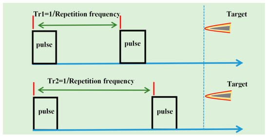
Figure 4.
Diagram of multi-repetition frequency.
2.3. Multi-Period Echo Signal Processing Method Based on the Improved Keystone Transform
This section uses the IrD-frequency fdesti(Vr) to calculate the ambiguity number of the estimated velocity. Based on the estimated IaD-frequency fdesti(i), the scale transformation factor is modified, and the IaD-frequency compensation function is constructed. The energy gain of the real target is improved, and the MTRC phenomenon is corrected to achieve the effective energy focusing of the multi-period radar echo of PSh-covered targets.
Perform Fourier transform on the fast time dimension of Equation (1) to obtain the frequency domain representation of the multi-period echo signal, as shown below:
where β(n) represents the phase term containing the target inter-pulse velocity information and the IaD-frequency information, which is specifically expressed as follows:
In the above equation, the related terms with frequency f and Doppler frequency fd(.) are as follows:
Among the above two equations, Equation (17) leads to the MTRC phenomenon of multi-period echo signals, and Equation (18) affects the generation of false targets.
According to Equation (17), the traditional keystone scale transformation factor is modified, and the improved scale transformation factor is as follows:
where tc is the virtual time corresponding to tq. It can be seen from Equation (19) that the slow-time dimension is stretched within the region where f < 0, and is compressed within the region where f > 0.
Accordingly, the compensation function of the IaD-frequency is designed based on Equation (18) for the phenomenon of the false target, to which the corresponding expressions are written as:
where I represents the estimated number of intra-pulse Doppler frequencies after performing FRFT transformation of the echo signal, i represents the i-th estimated intra-Doppler frequency of the pulse.
Establish a sinc-type interpolation function based on Equations (19) and (20), and process Equation (15), which is specifically expressed as follows:
Due to the high-velocity movement of the target, the velocity is usually blurred. Therefore, Equation (21) is further modified as follows:
where represents the phase correction function that can be expressed as:
In the above Equation (23), W represents the fuzzy number of the velocity, which is expressed as follows:
Based on the above research, the flow chart of the improved keystone algorithm is as follows in Figure 5 below:
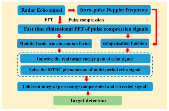
Figure 5.
The flowchart of improved the Keystone algorithm.
According to the above principle, the improved keystone processing is performed on Equation (21), and the IFFT operation is performed to obtain the processed signal, which is specifically expressed as follows:
where λ(n) represents the phase term containing the IaD-frequency, which is specifically expressed as follows:
By comparing the corresponding positions of the peak energy of the Sinc function contained in Equations (25) and (1), it is found that the term fd (Vr)(q − 1)Tr causes the MTRC phenomenon to disappear. When the term fd (n) − fdesti(i) is zero, the peak position of the Sinc function only correlates with the initial range R0 of the target. By accumulating all periods, the sum of I times energy accumulation is conducted at the target range, thereby forming a maximum energy peak at the initial range of the target.
3. Simulation and Analysis
This section uses computational plasma flow field simulation data [20]. The simulation of multi-period radar echo is carried out for the target under typical flight altitude and flight velocity.
Through time-frequency analytical results of the target radar echo in simulation Equation (1), the multi-frequency information contained in the echo signal is therefore determined. Through the method of multi-repetition frequency, the IrD-frequency frequency of the target is estimated. Based on the two kinds of Doppler frequencies, the improved Keystone algorithm proposed in this paper can solve the MTRC phenomenon while achieving the energy accumulation of the real target. The corresponding simulation parameters are listed in Table 2.

Table 2.
Simulation parameters.
3.1. Echo Signal Processing of PSh-Covered Targets
This section uses the FRFT method to calculate the radar echo’s time-frequency domain to obtain the echo coupling’s IaD-frequency component. Analyze the period-range two-dimensional distribution of the multi-period echo signal, and determine the Doppler frequency corresponding to the velocity of the target based on the method of multi-repetition frequencies.
Figure 6 shows the FRFT result of the radar echo signal from the PSh-covered target. As the time axis rotates counterclockwise, the energy accumulation of the echo signal on the time axis gradually increases. When the rotation angle of the time axis is perpendicular to the modulation frequency of the signal, the signal energy accumulates to form a peak, and an approximate ‘discrete’ phenomenon is formed in the two-dimensional order-frequency plane. Due to the relative motion characteristics of the PSh and the target, the Doppler frequency component ‘f0 + fd(n)’ in the echo signal coupling pulse is caused, and there are multiple energy peak points as the result of FRFT transformation.
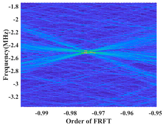
Figure 6.
Time-frequency result of echo radar.
Figure 6 is a U-axis slice of the result of FRFT transformation of the PSh-covered target. It is known that during the FRFT transformation, the angle axis only affects the estimation of the modulation frequency in the echo signal. Based on Equation (1), it can be obtained that the PSh does not affect the modulation frequency. Steps include fixing the coordinate axis position corresponding to the modulation frequency, slicing the order axis (U axis), and obtaining the echo signal carrier frequency projection on the U axis. Through the analysis of the U-axis slice of the FRFT transform result, it is found that three Doppler frequency components (Doppler frequency within the pulse generated by the PSh) are coupled in the echo. By extracting the peak values of the three peak values of IaD-frequency, the obtained frequencies are 0.538 MHz, 0.256 MHz, and 0.0259 MHz, respectively. It can be deduced that the maximum value of the IaD-frequency only quantitatively approximates the value of the IrD-frequency but differs in physical meanings, to which the specific expression can be written as
Figure 7 shows the pulse compression comparison of the echo signals of different periods of the PSh-covered target (comparison results of the first period and the last period), in which there are three blue peaks and three red peaks, indicating a significant MTRC phenomenon.
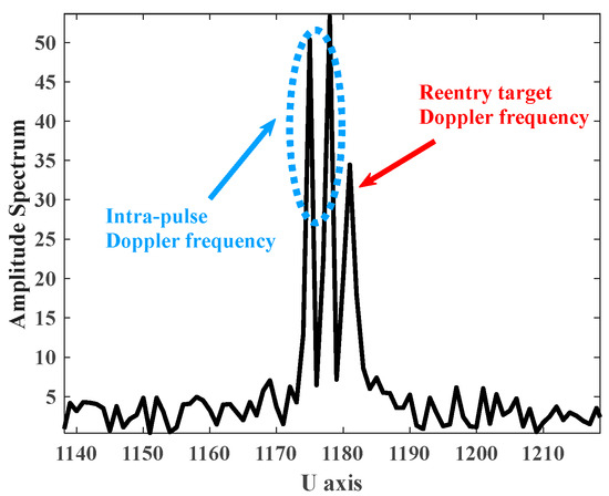
Figure 7.
Slicing diagram of the target echo signal’s time-frequency results with PSh.
In a single period, the IaD-frequency causes an increase in the number of peaks on the one-dimensional range profile, and the deviation of the peak position between multiple periods is caused by the bandwidth limitation of the radar transmission signal and the Doppler frequency between pulses.
As shown in Figure 8, the pulse compression of the multi-period echo signal results in multiple oblique straight lines parallel to each other. Since the simulation in this paper is a steady-state PSh (the target is at a constant velocity and a fixed flying height), the Doppler frequency component coupled in the echo does not change, and the PSh and the target are in a state of accompanying flight at all times, so there are multiple inclined straight lines in the two-dimensional period-range plane of the multi-period echo signal.
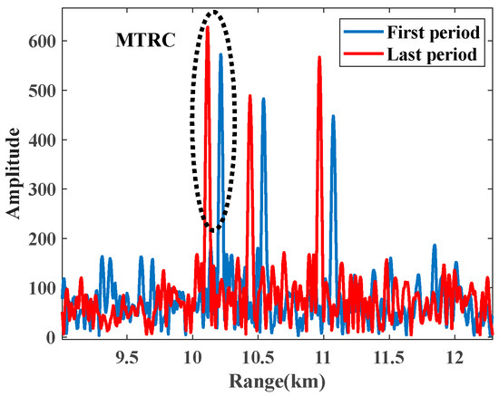
Figure 8.
Pulse compression results.
It can be seen from Figure 9 that the coherent integration processing is performed on the pulse compression result of the multi-period echo signal, and the peak energy of the two-dimensional range-Doppler frequency plane is diffused. The velocity of the target is extremely high, which is far greater than the maximum velocity range of the radar, and the limitation of the radar transmission signal bandwidth makes the range resolution unit limited, resulting in an obvious MTRC phenomenon in the multi-period echo signal, and the peak energy of the target cannot be effectively accumulated.
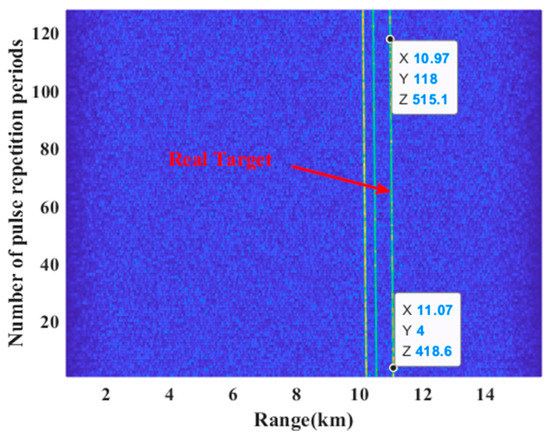
Figure 9.
Pulse compression result of multi-period echo signal.
As shown in Figure 10, the change of repetition period (1/repetition frequency) affects the result of coherent integration. The repetition period of the transmitted radar signal is increased from 100 µs to 130 µs, and the corresponding repetition frequency is reduced from 10 KHz to 7.692 KHz. When the repetition period is 100 µs, the maximum velocity that the radar can measure is 0.23 Ma (corresponding to the Doppler frequency 5000 Hz), the coherent integration result of the target is on the 43rd Doppler channel, and the measured velocity is −27 m/s (corresponding to Doppler frequency is −1719 Hz). When the repetition period is 130 µs, the maximum velocity that the radar can measure is 0.18 Ma (corresponding to the Doppler frequency is 3846 Hz), the coherent integration result of the target is on the 64th Doppler channel, and the measured velocity is −1 m/s (corresponding to Doppler frequency is −60 Hz). Aiming at the target’s actual velocity of the target far greater than the maximum velocity that the radar can measure, based on Equation (14), the IrD-frequency estimated value is 0.53 through the optimization search, the corresponding velocity is 24.7 Ma, and the velocity measurement error is 0.98%.
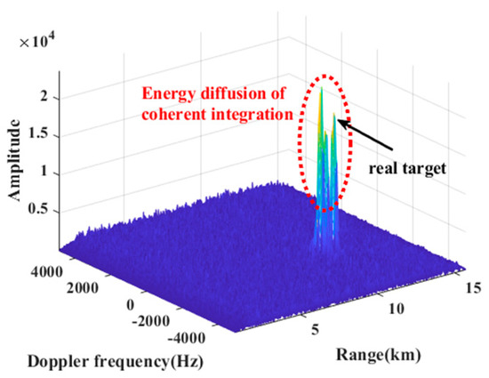
Figure 10.
Coherent integration results (Tr = 100 µs).
Combined with the simulation results of Figure 10 and Figure 11, the conclusion drawn from Equation (27) is that the maximum IaD-frequency is similar to the IrD-frequency. Fixing the repetition period (1/repetition frequency) of the radar signal, based on Equation (24), the fuzzy numbers obtained by the two kinds of Doppler frequencies are the same, and the ambiguity number will provide a priori parameters for the improved keystone algorithm.
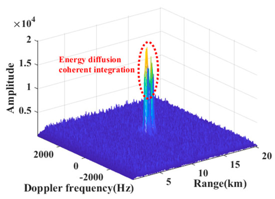
Figure 11.
Coherent integration results (Tr = 130 μs).
3.2. The Improved Keystone Algorithm
According to the prior parameters obtained in Section 3.1, based on the improved keystone algorithm proposed in this paper, as shown in Equation (22), the multi-period echo signal is processed, and simulation analysis is provided to verify the effectiveness of the algorithm in this paper.
As shown in Figure 12, the improved keystone algorithm based on this paper compensates for the multi-period echo signal, solves the MTRC phenomenon, and improves the energy gain of the real target (the energy of the real target is much greater than the energy of other targets). According to Equation (22), when fd(n) = fdesti(i), the peak value is compensated to the real target position (10 km), otherwise over-compensation occurs, and then an ‘over-compensated target group’ is formed, and multiple peaks appear on the one-dimensional range profile.
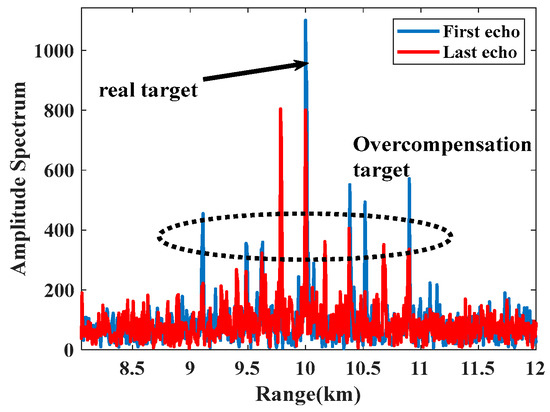
Figure 12.
Pulse compression results after compensating the MTRC based on the improved Keystone algorithm.
As shown in Figure 13, after the algorithm in this paper processes the multi-period echo signals of the plasma-sheath-covered target, the number of straight lines in the two-dimensional range-period plane increases, which is due to the existence of the overcompensation phenomenon and scaling factors mismatch phenomenon.
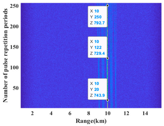
Figure 13.
Pulse compression result of multi-period echo signal after compensating based on the improved Keystone algorithm.
When the scaling factor is matched to the echo component, the slanted line is perpendicular to the range axis, and when the IaD-frequency is properly compensated, the peak position is located at 10 km. Due to the concentration of pulse energy during the accumulation of multiple compensations, the linear energy at 10 km is much larger than other linear energy.
It can be seen from Figure 14 that multiple peaks will occur after performing coherent integration with respect to Equation (25). Compared with Figure 10, it can be found that although the number of peaks increases, the energy diffusion is significantly alleviated. The algorithm in this paper solves the diffusion problem, thereby effectively accumulating the energy of the multi-period echo signal.
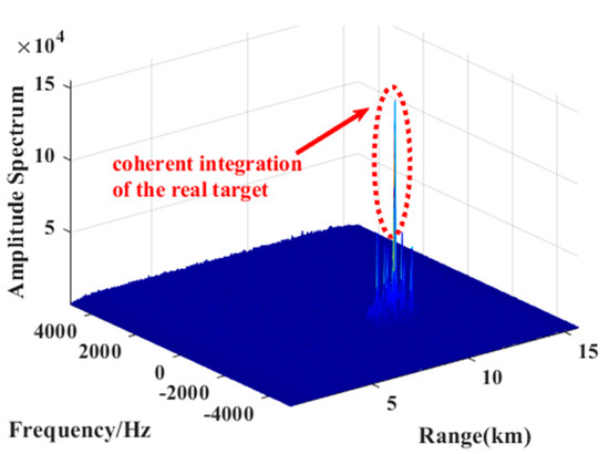
Figure 14.
Coherent integration result after compensating based on the improved Keystone algorithm.
As shown in Figure 15, the coherent integration result processed by the improved Keystone algorithm forms the largest energy peak at the target’s actual position. The energy at the real target position is much larger than the other peak energy.
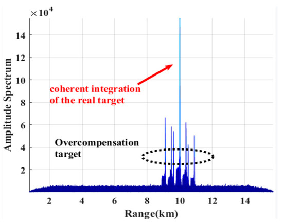
Figure 15.
Range–axis projection of coherent integration result after compensating based on the improved Keystone algorithm.
After compensation, the coherent integral energy gain of the real target is significantly improved, which is 9.8 times higher than that in Figure 9. By improving the keystone algorithm processing, the ratio of the real target energy to the maximum peak false target energy is increased from 0.83 to 2.583, an increase of 3.11 times.
3.3. Analysis of Simulation Experiment under Typical Parameter Conditions
In this section, according to the RAM-C data and radar parameter data in Table 2, the radar echo signal of the target at typical flight altitude and typical flight velocity is processed and calculates the energy ratio between the real target and the maximum false target at peak value. Meanwhile, different classical methods are used to process the multi-period echo signals in typical states, which further verifies the algorithm’s effectiveness in this paper. The processing results of multi-period echo signals are shown in Table 3.

Table 3.
Improved algorithm processing results.
From the above table, it can be concluded that the flight altitude and velocity of the target have an impact on the energy ratio after the improved keystone process. By comparing the energy ratio of the target at Mach 25 and Mach 15, it can be seen that the inhibition ratio of energy decreases as the velocity increases. Under the condition of the same relative movement velocity of the target, different flight heights will affect the energy ratio of the real target and the false target after compensation. This is because the density of air near the ground decreases as altitude increases. The gradual thinning of the PSh reduces the energy of the echo signal (low energy signals are easily overwhelmed by noise).
Shown in Figure 16 are the proposed method, frequency domain compensation algorithm and MTD method. When the real target energy is less than the false target energy, the traditional method can only detect the parameter information of the false target. When the false target is in a stable state, the error of detection results does not change. When the real target energy is greater than the false target energy, the traditional method can effectively detect the target. Compared with the improved algorithm in this paper, it can be seen that when the real target energy is less than the false target energy, the algorithm can effectively detect the real target, and when the signal-to-noise ratio is greater than −17 dB, the detection error of the real target is 0. With the decrease in signal-to-noise ratio, the accuracy of IaD-frequency extraction decreases, and the matching degree of the constructed scale transformation factor decreases. Therefore, the detection error of the improved algorithm increases.
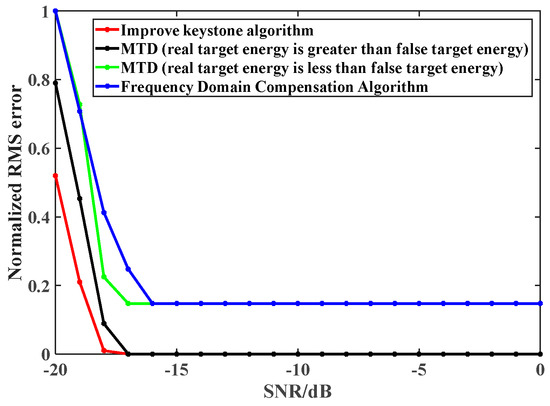
Figure 16.
Comparison algorithm verification (25 Ma/30 Km).
4. Conclusions
Based on the radar echo model of the plasma-sheath-covered target, the influence law of peak interval on the one-dimensional range profile of the echo signal is analyzed. By analyzing the distribution characteristics of the time-frequency domain, the characterization of IaD-frequency and IrD-frequency frequency is derived.
The IaD-frequency is used to modify the scale transformation factor, and the IrD-frequency is used to construct the compensation function so as to improve the traditional Keystone algorithm. The improved algorithm can effectively improve the energy gain of the real target, solve the MTRC phenomenon, and realize the reliable, coherent integration of multi-period radar echo.
Finally, the effectiveness of the proposed algorithm is verified by processing the multi-period echo signals at typical flight altitudes and velocities. The reliability of the algorithm is further verified by comparing it with the traditional algorithm. The research results of this paper lay a theoretical foundation for further reliable radar detection and stable tracking of plasma-sheath-covered targets.
Author Contributions
Conceptualization, Y.D. and B.B.; methodology, Y.D.; software, Y.D.; formal analysis, Y.D., B.B., X.L. and Y.L.; investigation, B.B., X.L. and Y.L.; writing—original draft preparation, Y.D.; writing—review and editing, Y.D.; supervision, B.B. All authors have read and agreed to the published version of the manuscript.
Funding
This work was supported in part by the National Natural Science Foundation of China under Grant Nos. 62171349, 62001388, and 61627901, in part by the Natural Science Basic Research Plan in Shaanxi Province of China under Grant No. 2020JM-102.
Acknowledgments
The authors would like to thank the handling editor and the anonymous reviewers for their careful reading and helpful remarks.
Conflicts of Interest
The authors declare no conflict of interest.
References
- Close, S.; Oppenheim, M.; Hunt, S.; Dyrud, L. Scattering characteristics of high-resolution meteor head echoes detected at multiple frequencies. J. Geophys. Res. Space Phys. 2002, 107, 9–12. [Google Scholar] [CrossRef]
- Kero, J.; Szasz, C.; Wannberg, G.; Pellinen-Wannberg, A.; Westman, A. On the meteoric head echo radar cross section angular dependence. Geophys. Res. Lett. 2008, 35, 154–162. [Google Scholar] [CrossRef]
- Luo, C.R.; Ding, C.L.; Duan, L.B. 12th Five-Year Plan Textbooks: Electrodynamics; Publishing House of Electronics Industry: Beijing, China, 2016; pp. 150–176. [Google Scholar]
- Cao, C. Basic Series of Modern Physics: Classical Electrodynamics; Science Press: Beijing, China, 2009; pp. 167–180. [Google Scholar]
- Liu, S.H.; Guo, L.X. Analyzing the Electromagnetic Scattering Characteristics for 3-D Inhomogeneous Plasma Sheath Based on PO Method. IEEE Trans. Plasma Sci. 2006, 44, 2838–2843. [Google Scholar] [CrossRef]
- Abatzoglou, T.J.; Gheen, G.O. Range, radial velocity, and acceleration MLE using radar LFM pulse train. IEEE Trans. Aerosp. Electron. Syst. 1998, 34, 1070–1084. [Google Scholar] [CrossRef]
- Zhang, X.; Liu, Y.; Bai, B.; Li, X.; Shen, F.; Chen, X.-Y.; Zhao, L. Establishment of a Wideband Radar Scattering Center Model of a Plasma Sheath. IEEE Access 2019, 7, 140402–140410. [Google Scholar] [CrossRef]
- Ding, Y.; Bai, B.; Gao, H.; Liu, Y.; Li, X.; Zhao, M. Method of Detecting a Target Enveloped by a Plasma Sheath Based on Doppler Frequency Compensation. IEEE Trans. Plasma Sci. 2020, 48, 4103–4111. [Google Scholar] [CrossRef]
- Carretero-Moya, J.; Gismero-Menoyo, J.; Asensio-Lopez, A.; Blanco-Del-Campo, A. A coherent Radon transform for small target detection. In Proceedings of the 2009 IEEE Radar Conference, Pasadena, CA, USA, 4–8 May 2009; pp. 1–4. [Google Scholar]
- Li, Y.; Zeng, T.; Long, T.; Wang, Z. Range migration compensation and Doppler ambiguity resolution by keystone transform. In Proceedings of the IEEE International Radar Conference, Shanghai, China, 9–12 October 2006. [Google Scholar]
- Wan, J.; Zhou, Y.; Zhang, L.; Chen, Z. A Doppler Ambiguity Tolerated Method for Radar Sensor Maneuvering Target Focusing and Detection. IEEE Sens. J. 2019, 19, 6691–6704. [Google Scholar] [CrossRef]
- Perry, R.P.; Dipietro, R.C.; Fante, R.L. SAR imaging of moving targets. IEEE Trans. Aerosp. Electron. Syst. 1999, 35, 188–200. [Google Scholar] [CrossRef]
- Zhang, S.-S.; Zeng, T.; Long, T.; Yuan, H.-P. Dim target detection based on keystone transform. In Proceedings of the IEEE International Radar Conference, Yantai, China, 9–12 May 2005. [Google Scholar]
- Zhu, D.; Li, Y.; Zhu, Z. A keystone transform without interpolation for SAR ground moving-targetimaging. IEEE Geosci. Remote Sens. Lett. 2007, 4, 18–22. [Google Scholar] [CrossRef]
- Ding, Y.; Bai, B.; Gao, H.; Niu, G.; Shen, F.; Liu, Y.; Li, X. An Analysis of Radar Detection on a Plasma Sheath Covered Reentry Target. IEEE Trans. Aerosp. Electron. Syst. 2021, 57, 4255–4268. [Google Scholar] [CrossRef]
- Wang, R.; Zhang, T.; Cui, K.; Yu, T.; Jiang, Q.; Zhang, R.; Li, J.; Hu, C. High-Resolution and Low Blind Range Waveform for Migratory Insects’ Taking-Off and Landing Behavior Observation. Remote Sens. 2022, 14, 3034. [Google Scholar] [CrossRef]
- Song, Y.; Wang, Y.; Xie, J.; Yang, Y.; Tian, B.; Xu, S. Ultra-Low Sidelobe Waveforms Design for LPI Radar Based on Joint Complementary Phase-Coding and Optimized Discrete Frequency-Coding. Remote Sens. 2022, 14, 2592–2612. [Google Scholar] [CrossRef]
- Chen, S.; Zhang, S.; Zhao, H.; Chen, Y. A New Chirp Scaling Algorithm for Highly Squinted Missile-Borne SAR Based on FRFT. IEEE J. Sel. Top. Appl. Earth Obs. Remote Sens. 2015, 8, 3977–3987. [Google Scholar] [CrossRef]
- Pang, N.; Xu, P. A new acceleration estimation method based on special FRFT in MIMO radar. In Proceedings of the IET International Radar Conference, Hangzhou, China, 14–16 October 2015; pp. 1–5. [Google Scholar]
- Chen, W.F.; Zhao, W.W. Rarefied Gas Dynamic Moment Method and Numerical Simulation; Science Press: Beijing, China, 2017; pp. 252–258. [Google Scholar]
Publisher’s Note: MDPI stays neutral with regard to jurisdictional claims in published maps and institutional affiliations. |
© 2022 by the authors. Licensee MDPI, Basel, Switzerland. This article is an open access article distributed under the terms and conditions of the Creative Commons Attribution (CC BY) license (https://creativecommons.org/licenses/by/4.0/).