Article

The Computational Optimization of the Invariant Imbedding T Matrix Method for the Particles with N-Fold Symmetry

School of Meteorology and Oceanography, National University of Defense Technology, Changsha 410073, China
*
Author to whom correspondence should be addressed.
Remote Sens. 2022, 14(16), 4061; https://doi.org/10.3390/rs14164061
Submission received: 30 June 2022 / Revised: 4 August 2022 / Accepted: 17 August 2022 / Published: 19 August 2022

Abstract

:
The invariant imbedding T-matrix (IIM T-matrix) model is regarded as one of the most promising models for calculating the scattering parameters of non-spherical particles. However, the IIM T-matrix model needs to be iterated along the radial direction when calculating the T-matrix, which involves complex calculations such as matrix inversion and multiplication. Therefore, how to improve its computational efficiency is an important problem to be solved. Focused on particles with N-fold symmetric geometry, this paper deduced the symmetry in the calculation process of the IIM T-matrix model, derived the block iteration scheme of the T-matrix, and contracted the IIM T-matrix program for particles with N-fold symmetric geometry. Discrete Dipole Approximation (DDA) and Geometrical Optics Approximation (IGOA) were employed to verify the accuracy of the improved IIM T-matrix model. The results show that the six phase matrix elements (P11, P12/P11, P22/P11, P33/P11, P34/P11 and P44/P11) calculated by our model are in good agreement with other models. The computational efficiency of the improved IIM T-matrix model was further investigated. As demonstrated by the results, the computational efficiency for the particles with N-fold symmetry improved by nearly 70% with the improvement of the symmetry of U matrix and T matrix. In conclusion, the improved model can remarkably reduce the calculation time while maintaining high accuracy.

Graphical Abstract

1. Introduction

Atmospheric radiative transfer models have been widely used in the fields of atmospheric remote sensing [1] and climate numerical simulation. The accuracy of radiative transfer simulation primarily depends on the scattering parameters of atmospheric particles, which is the basic input of atmospheric radiative transfer model [2]. Previously, the particles’ scattering properties were generally calculated using the Lorenz–Mie theory. However, the scattering parameters of the Lorenz–Mie theory may seriously deviate from the actual light scattering characteristics due to the irregular shape of atmospheric particles, especially for the polarization of the scattered light [3,4]. In recent years, polarized remote sensing gradually developed, and accurately understanding the influence of particle shape on the polarization characteristics of the atmospheric radiation has become a key step to improving the remote sensing of aerosols and ice clouds [4]. Therefore, the calculation of the scattering parameters of the non-spherical particles has become an international research hotspot [5,6,7,8].
The T-matrix method is one of the important methods to calculate the atmospheric non-spherical particles’ light scattering properties. Once the T matrix is obtained in a one-time calculation, the scattering properties of the randomly oriented particles can be analytically calculated. Waterman first proposed using the extended boundary method (EBCM) to calculate the T matrix in 1965 [9]. In the 1990s, Mishchenko improved the extended boundary condition method and proposed an analytical calculation scheme for the scattering parameters of randomly oriented particles (including extinction cross section, absorption cross section and phase matrix), based on which an efficient computation code for rotationally symmetric particles was developed (Mishchenko [10], 1991; Mishchenko and Travis, 1998). At present, this code is widely used in the fields of atmospheric radiation and remote sensing. Because EBCM is essentially a surface integration scheme, the model is mainly applicable to rotationally symmetric particles due to the limitation of boundary conditions. Besides, for particles with large parameters and a large complex refractive index, the calculation process might become non-convergent [11]. Therefore, many scholars have begun to use other methods to calculate the T matrix [12,13,14,15,16]. Schulz et al. proposed the calculation of a T matrix by separating variables [17]; Mackowski et al. tried to use Discrete Dipole Approximation (DDA) to calculate the T matrix [18], and Loke et al. proposed calculating the T matrix by combining DDA and the point matching method [19]. However, these methods can only be used to calculate the light scattering processes of small particles. The IIM T-matrix model (Invariant Imbedding T-matrix Method) is a new method by which to calculate the T-matrix, which was first proposed by Johnson et al. in 1988 [20]. However, due to the limitation of computing power at that time, this method did not draw enough attention. With the development of computer technology, Yang P. and L. Bi proposed an efficient implementation of the invariant imbedding T-matrix method, which combined the invariant imbedding iteration technique with SVM (Separation of Variables Method) and EBCM [21,22]. At present, the model is applied to calculate the light scattering of large particles with arbitrary shapes, such as ice crystals, non-spherical aerosol particles [23], and so on. In recent years, Hu et al. [11] independently developed the Invariant Imbedding T-matrix model, which successfully combined Lorenz Mie scattering theory with an invariant imbedding iteration technique. To improve the calculation efficiency of the model, our team systematically derived the symmetry of the invariant imbedding T-matrix, and proposed an implicit iterative solution method for the T-matrix, which improved the calculation efficiency of the model by nearly 30% [24,25,26].
Despite its advantages in the light scattering simulation of non-spherical particles, the computational efficiency of the invariant imbedding T-matrix method is still far lower than that of EBCM. The reason is that the IIM T-matrix method needs a layer-by-layer iteration along the radial direction, which involves large matrix operations. Since these matrix dimensions are proportional to the square of the expansion order of the electromagnetic field, for particles with a slightly larger size parameter, the matrix dimension is over 10,000. Therefore, most time will be spent on computational processes such as the calculation of the U matrix, matrix multiplication and matrix inversion, and the memory consumption will also become huge for large particles [5,27]. Besides, in order to build the scattering parameters database, the scattering parameters of particles with different size parameters and shapes for different wavelengths need to be calculated. Therefore, if the scattering computation of a single particle is too time-consuming it will become a challenging task. As a result, reducing the computational burden of the matrix operations to accelerate the foundation of the scattering database is an important responsibility of the IIM T-matrix method. In 2019, Doicu et al. [28] studied the new recurrence formula for the IIM T-matrix model, in which the two matrix inversion processes in T-matrix iteration can be reduced to one. In principle, it can greatly shorten the calculation time. In the actual atmospheric radiative transfer simulation, the particles with symmetrical geometry are usually used to approximate the non-spherical particles. For example, ice crystal particles are usually represented by a hexagonal prism and disk-shaped particles, and aerosol can be approximated as ellipsoid, cylinder or super ellipsoid, etc. By employing the extended boundary condition method, Waterman, Mishchenko and Schulz [21,29,30] found that, for particles with a symmetric structure, the T matrix can be transformed into a block diagonal matrix. For example, for rotating symmetric ellipsoidal particles and hexagonal prism particles, the T matrix can be seen as a block diagonal matrix related to the azimuth mode m. Since each diagonal submatrix can be calculated independently, this method can greatly reduce the matrix calculation and memory consumption. The idea should be generalized and we applied it to accelerate the IIM T-matrix method in this study. In this paper, the symmetry of the U matrix was derived and the iteration of T matrix was also simplified for N-fold symmetric geometrical particles. This work can greatly improve the calculation efficiency of particles with N-fold symmetric geometry and provide an effective calculation scheme to construct the particle scattering parameter database.
This paper is divided into five sections. In Section 2, the basic principle of the invariant imbedding T-matrix method is introduced. In Section 3, the symmetry of the U matrix is systematically derived, and the block iterative method for solving the T matrix is proposed subsequently. In Section 4, in order to verify the accuracy of the model, the calculation results are compared with those of discrete dipole approximation, geometric optics approximation and other models. Moreover, the calculation efficiency of the model is also tested. In Section 5, a discussion of the results is presented. Lastly, a summary of this paper is provided in Section 6.

2. Invariant Imbedding T-Matrix Algorithm

The T matrix is a linear transformation matrix of the incident and scattering field. By using the T matrix of the nonspherical particle, the scattering field can be calculated once the incident light is known, and is written as
p 1 q 1 p l max q l amx = T 11 11 T 11 12 T 1 , l max 11 T 1 , l max 12 T 11 21 T 11 22 T 1 , l max 21 T 1 , l max 22 T l max , 1 11 T l max , 1 12 T l amx , l max 11 T l amx , l max 12 T l max , 1 21 T l max , 1 22 T l max , l max 21 T l max , l max 22 a 1 b 1 a l max b l max
in which, ai and bi (i = 1,2, l max ) are the expansion coefficients of the incident wave, and pi and qi(i = 1,2, l max ) are the expansion coefficients of the incident wave.
The invariant imbedding T-matrix model calculates the T matrix by solving the Helmholtz volume integral equation in the frequency domain. After expansion and discretization of the spherical harmonic vector wave function, its form can be converted as follows:
E m n ( r , θ , φ ) = Y ¯ ¯ m n ( θ , φ ) J ¯ ¯ n ( k r ) + 0 R d r n = 1 m = n n Y ¯ ¯ m n ( θ , φ ) H ¯ ¯ n ( k r ) T ¯ ¯ m n m n
In which, J ¯ ¯ n ( k r ) is a large matrix composed of Bessel functions of the first kind, and H ¯ ¯ n ( k r ) is a large matrix composed of Hankel functions of the first kind. Y ¯ ¯ n m ( θ , φ ) is the angle function matrix
Y ¯ ¯ m n ( θ , φ ) = [ A m n ( θ , φ ) , B m n ( θ , φ ) , C m n ( θ , φ ) ] ; A m n ( θ , φ ) = ( 2 n + 1 4 π n ( n + 1 ) ) 1 / 2 ( 1 ) m exp ( i m φ ) [ θ ^ i π m n ( θ ) φ ^ τ m n ( θ ) ] ; B m n ( θ , φ ) = ( 2 n + 1 4 π n ( n + 1 ) ) 1 / 2 ( 1 ) m exp ( i m φ ) [ θ ^ i τ m n ( θ ) φ ^ π m n ( θ ) ] ; C m n ( θ , φ ) = ( 2 n + 1 4 π n ( n + 1 ) ) 1 / 2 ( 1 ) m exp ( i m φ ) [ n ( n + 1 ) k r d o m n ( θ ) r ^ ] ;
In which, d 0 m n represents Wigner-d functions, and π m n ( θ ) and τ m n ( θ ) are the angular functions derived from Wigner-d functions. These three can be combined into regular vector spherical harmonics and vector spherical harmonics, and then the specific calculation form of the T matrix can be derived:
T ¯ ¯ m n m n = i k j = 1 N ω j J ¯ ¯ n ( k r j ) F ¯ ¯ m n m n ( r j )
In the formula above, ω n is Gaussian weight and F ¯ ¯ m n m n ( r j ) is calculated as follows:
F ¯ ¯ m n m n ( r i ) = U ¯ ¯ m n m n ( r i ) J ¯ ¯ n ( k r i ) + j = 1 N ω j n ˜ = 1 m ˜ = n ˜ n ˜ U ¯ ¯ m n m n ( r i ) g ¯ ¯ n ˜ ( r i , r j ) F m ˜ n ˜ m n ( r j )
in the formula above, g ¯ ¯ n ˜ ( r i , r j ) = i k H ¯ ¯ ( r n ) J ¯ ¯ T ( r n ) , i is the unit complex number, the U matrix is defined as
U ¯ ¯ m n m n ( r ) = r 2 Ω d Ω ( Y ¯ ¯ * m n ( θ , φ ) ) T u ( r ) Z ¯ ¯ ( r ) Y ¯ ¯ m n ( θ , φ )
By using the invariant imbedding technique, the iterative equation can be derived from Equations (4)–(6), written as [22]
T ¯ ¯ ( r n ) = Q ¯ ¯ 11 ( r n ) + ( I ¯ ¯ + Q ¯ ¯ 12 ( r n ) ) I ¯ ¯ T ¯ ¯ ( r n 1 ) Q ¯ ¯ 22 ( r n ) 1 T ¯ ¯ ( r n 1 ) I ¯ ¯ + Q ¯ ¯ 21 ( r n )
where, rn is the radius of the nth layer, T ¯ ¯ ( r n ) and T ¯ ¯ ( r n 1 ) are the T matrix of the spheres of n layers and n − 1 layers, Q ¯ ¯ 11 ( r n ) , Q ¯ ¯ 12 ( r n ) , Q ¯ ¯ 21 ( r n ) and Q ¯ ¯ 22 ( r n ) are the optical matrix of the nth spherical shell, which can be calculated using the Q ¯ ¯ ( r n ) matrix, written as
Q ¯ ¯ 11 ( r n ) = J ¯ ¯ T ( r n ) Q ¯ ¯ ( r n ) J ¯ ¯ ( r n )
Q ¯ ¯ 12 ( r n ) = J ¯ ¯ T ( r n ) Q ¯ ¯ ( r n ) H ¯ ¯ ( r n )
Q ¯ ¯ 21 ( r n ) = H ¯ ¯ T ( r n ) Q ¯ ¯ ( r n ) J ¯ ¯ ( r n )
Q ¯ ¯ 22 ( r n ) = H ¯ ¯ T ( r n ) Q ¯ ¯ ( r n ) H ¯ ¯ ( r n )
The calculation formula of the Q ¯ ¯ ( r n ) matrix is as follows:
Q ¯ ¯ ( r n ) = ω n [ I ¯ ¯ ω n U ¯ ¯ ( r n ) g ¯ ¯ ( r n , r n ) ] 1 U ¯ ¯ ( r n ) ;
In the actual calculation process of the IIM T-matrix method, the non-spherical particles are regarded as an inhomogeneous sphere and discretized into a certain number of inhomogeneous spherical shells from R0 to RN in the spherical coordinate system (R1 and R2 are the radii of the inscribed and circumscribed sphere of the particle), as shown in Figure 1. To improve the modeling efficiency, the T matrix of the inscribed sphere is firstly calculated by employing the Lorenz–Mie theory, and then, the T matrix is updated layer by layer using the invariant imbedding technique (see Equation (7)).
In the T-matrix calculation process, the U matrix is the most important matrix because it contains optical and geometrical information about particles, such as particle shape, particle complex refractive index, etc. Therefore, the calculation of the U matrix is an important step in the calculation. However, its calculation is a highly time-consuming process in the IIM T-matrix method. Therefore, in the third section, the optimization theory for calculating the U matrix is firstly derived.

3. Optimization Method for Calculating Scattering Parameters of Particles with N-Fold Symmetric Geometry

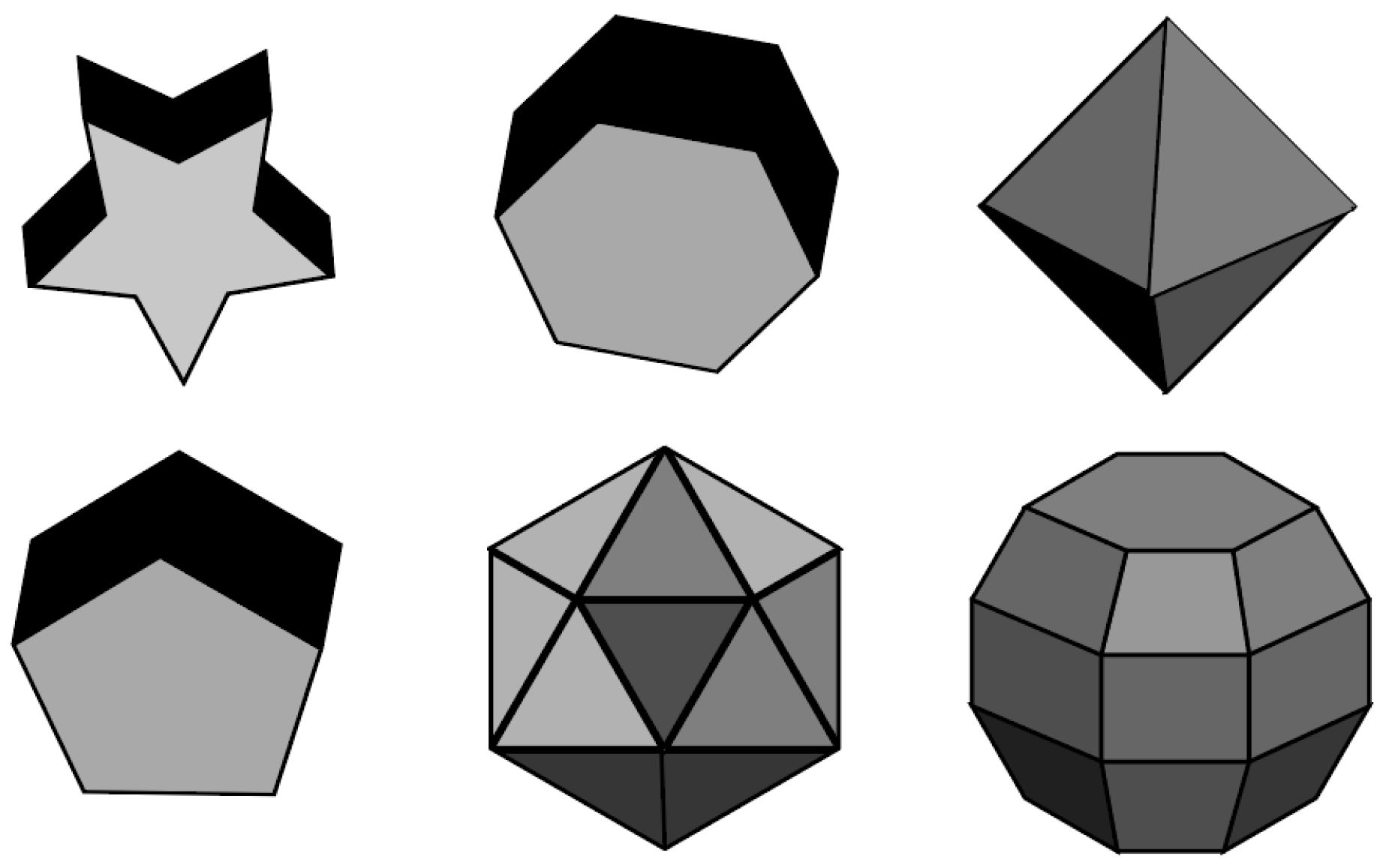
The particles with N-fold symmetric geometry (After the particle rotates a fixed angle around an axis perpendicular to the center of the particle plane, it completely coincides with the original particle) are generally taken as the approximation of non-spherical particles, such as a hexagonal prism, disk-shaped particles, super ellipsoid, etc., [24,29], as shown in Figure 2. In this section, we focus on deriving the symmetrical properties of the U matrix, and on improving the implementation of the IIM T-matrix method.

3.1. Computational Optimization Based on Symmetry Property of U Matrix

The calculation formula of the U matrix can be written as:
U ¯ ¯ m n m n ( r ) = k 2 r 2 ( 1 ) m + m [ 2 n + 1 4 π n ( n + 1 ) ] 1 / 2 [ 2 n + 1 4 π n ( n + 1 ) ] 1 / 2 0 2 π d φ 0 π d θ sin θ exp [ i ( m m ) φ ] [ ε r ( r , θ , φ ) 1 ] × π m n ( θ ) π m n ( θ ) + τ m n ( θ ) τ m n ( θ ) i [ π m n ( θ ) τ m n ( θ ) + τ m n ( θ ) π m n ( θ ) ] 0 i [ π m n ( θ ) τ m n ( θ ) + τ m n ( θ ) π m n ( θ ) ] π m n ( θ ) π m n ( θ ) + τ m n ( θ ) τ m n ( θ ) 0 0 0 n ( n + 1 ) n ( n + 1 ) d 0 m n d 0 m n ε r ( r , θ , φ )
For the particles with N-fold symmetric geometry, we can extract the integral of φ as follows:
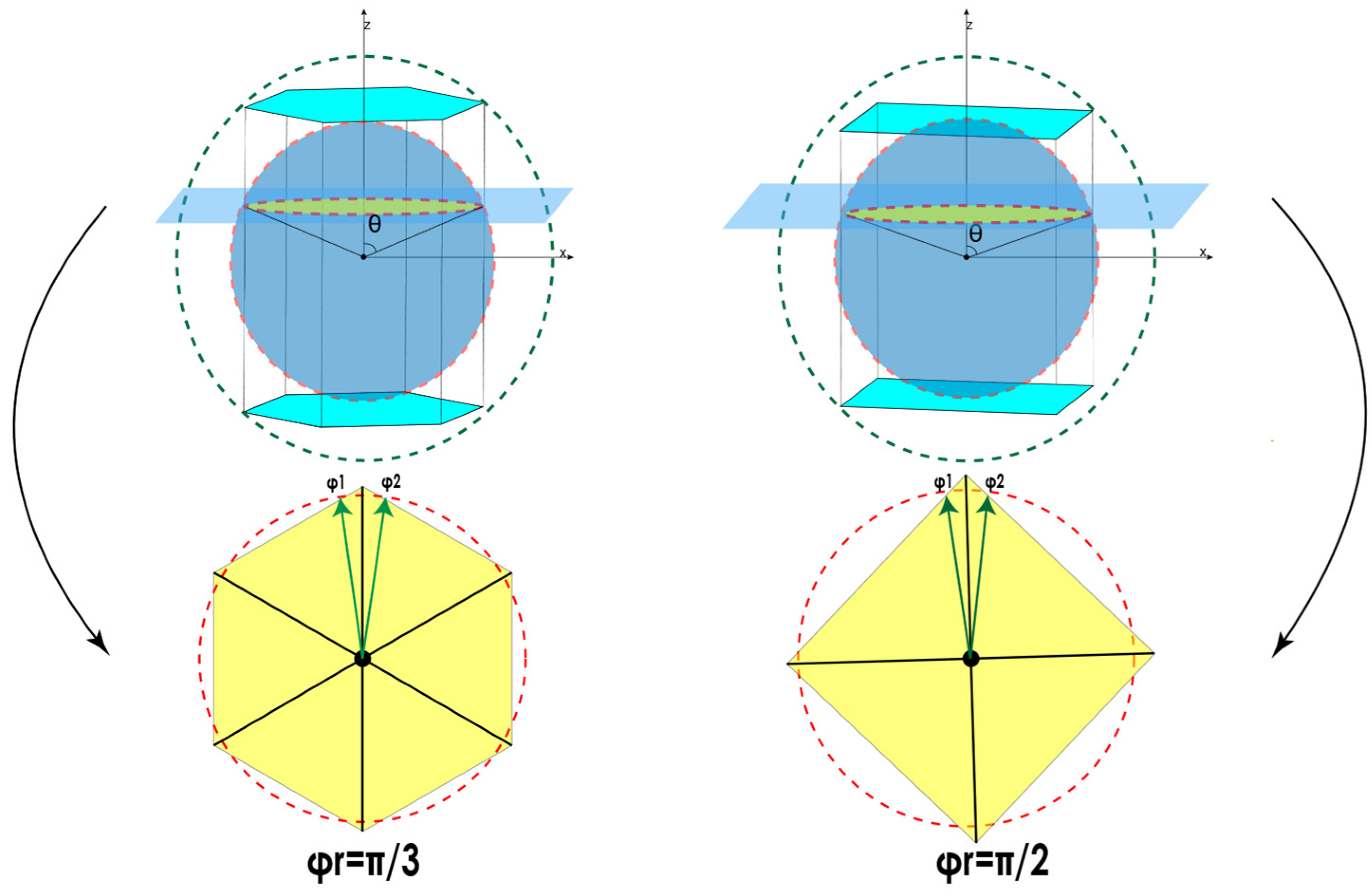
0 2 π exp [ i ( m m ) φ ] [ ε r ( r , θ , φ ) 1 ] d φ = φ 1 φ 2 exp [ i ( m m ) φ ] [ ε r ( r , θ , φ ) 1 ] d φ + φ 1 + 2 π N φ 2 + 2 π N exp [ i ( m m ) φ ] [ ε r ( r , θ , φ ) 1 ] d φ + φ 1 + 2 π N ( N 1 ) φ 2 + 2 π N ( N 1 ) exp [ i ( m m ) φ ] [ ε r ( r , θ , φ ) 1 ] d φ = k = 0 N 1 φ 1 + 2 π N k φ 2 + 2 π N k exp [ i ( m m ) φ ] [ ε r ( r , θ , φ ) 1 ] d φ
φ 1 and φ 2 in the above formula are shown in Figure 3.
Through simplification, Equation (14) can be expressed as follows (see Appendix A for detailed derivation):
0 2 π exp [ i ( m m ) φ ] d φ = 2 N m m exp [ i ( m m ) φ 2 + φ 1 2 ] sin [ ( m m ) φ 2 φ 1 2 ] δ | m m | , N l
From the equation above, it can be found that for the particles with N-fold symmetric geometry, the calculation of the U matrix only needs to be carried out at | m m | = 0 / N l , which greatly reduces the calculation amount.

3.2. Calculation Optimization of T-Matrix Iteration Process

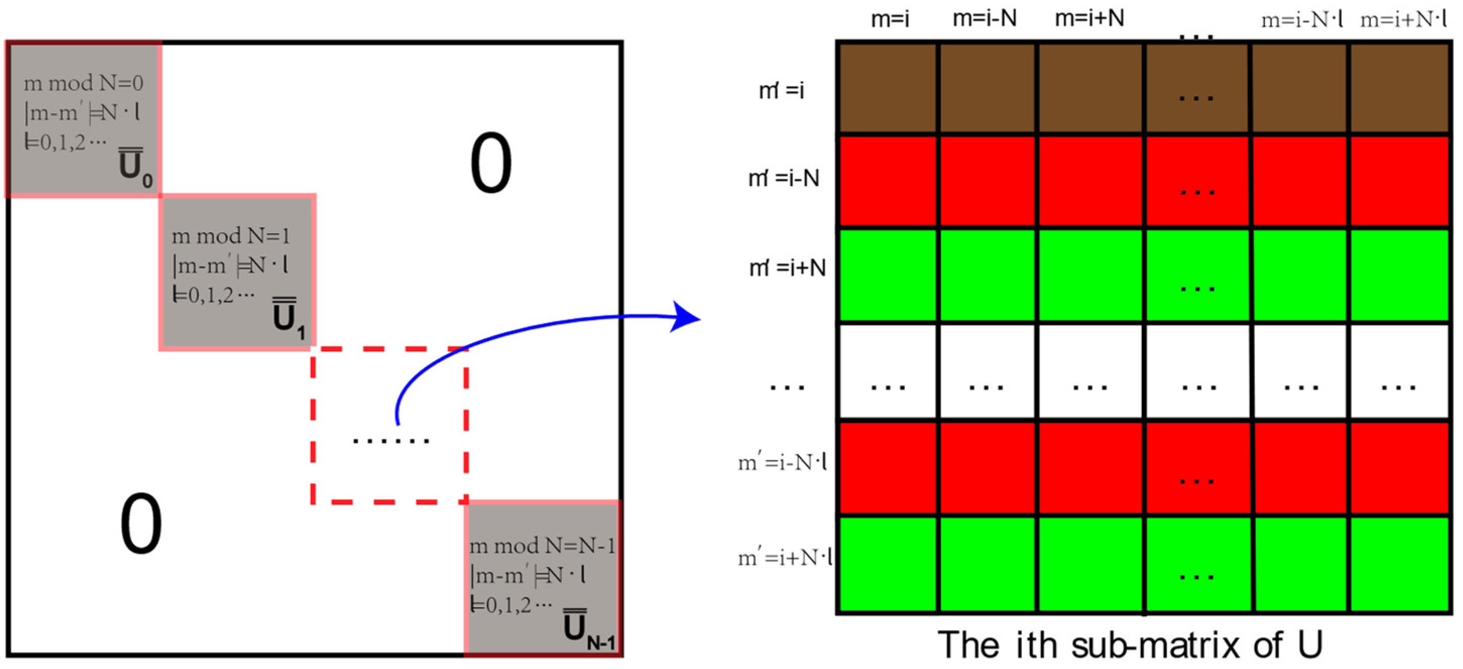
It has been found that when | m m | 0 / N l , the U matrix is 0. In order to reduce the computational complexity of matrix multiplication, we rearranged the U matrix in the following way: extracting the sub-U matrix of | m m | = 0 / N l and arranging it along the diagonal of the U matrix, as shown in Figure 4.
Similarly, the Q matrix can also be transformed into a block diagonal matrix. According to the IIM T-matrix theory, the Q matrix is calculated using the U matrix with the following equation:
Q ¯ ¯ ( r n ) = ω n I ¯ ¯ ω n U ¯ ¯ ( r n ) g ¯ ¯ ( r n , r n ) 1 U ¯ ¯ ( r n )
Because the matrix element of g ¯ ¯ ( r n , r n ) is independent of the azimuthal mode m [20,22,31], we can rearrange the layout of the matrix element of g ¯ ¯ ( r n , r n ) into an N-block diagonal matrix according to the arrangement rule of the U matrix [20,22], as shown in Figure 5.
Obviously, after g ¯ ¯ ( r n , r n ) is transformed into a block diagonal matrix, it can be easily found that the Q matrix should also be a block diagonal matrix (with N blocks). The ith sub-matrix block, i.e., Qi, can be calculated as follows:
Q ¯ ¯ w ( r n ) = ω n I ¯ ¯ ω n U ¯ ¯ w ( r n ) g ¯ ¯ w ( r n , r n ) 1 U ¯ ¯ w ( r n )
where w represents the wth block of the diagonal matrix. Since the Bessel matrix and the Hankel matrix are also independent of the azimuth mode m, they can also be converted to the form of a block diagonal matrix. For this, the calculation method of each block of Q i j ( r n ) can be found as follows:
Q ¯ ¯ 11 w ( r n ) = i k J ¯ ¯ w T ( r n ) Q ¯ ¯ w ( r n ) J ¯ ¯ w ( r n )
Q ¯ ¯ 12 w ( r n ) = i k J ¯ ¯ w T ( r n ) Q ¯ ¯ w ( r n ) H ¯ ¯ w ( r n )
Q ¯ ¯ 21 w ( r n ) = i k H ¯ ¯ w T ( r n ) Q ¯ ¯ w ( r n ) J ¯ ¯ w ( r n )
Q ¯ ¯ 22 w ( r n ) = i k H ¯ ¯ w T ( r n ) Q ¯ ¯ w ( r n ) H ¯ ¯ w ( r n )
So far, all the matrices in Equation (7) become a block diagonal matrix. So, the whole calculation process can be converted to the calculation of the block diagonal matrix, which is written as
T ¯ ¯ w ( r n ) = Q ¯ ¯ 11 w ( r n ) + ( I ¯ ¯ + Q ¯ ¯ 12 w ( r n ) ) [ I ¯ ¯ T ¯ ¯ w ( r n 1 ) Q ¯ ¯ 22 w ( r n ) ] 1 T ¯ ¯ w ( r n 1 ) [ I ¯ ¯ + Q ¯ ¯ 21 w ( r n ) ]
After all the block diagonal sub-matrices are obtained, they can be combined into a complete T-matrix. Thus, the scattering parameters can calculated in the same manner as that in the EBCM T-matrix method developed by Mishchenko et al.

4. Results

To validate the effectiveness of our model, hexagonal prism, octagonal prism and twelve prism particles were selected as examples for verification. The calculation results of their scattering parameters were compared with those of DDA (small particles case) and IGOA (large particle case). Further, the computational efficiency of the optimized IIM T–matrix model was also investigated.

4.1. Small Particle Case

In this section, we compare the numerical results computed by the IIM T-matrix method with their counterparts computed using DDA and ADDA, where the particles used for model validation include the hexagonal prism particles, octagonal prism particles and twelve prism particles.
(1)
Hexagonal prism case
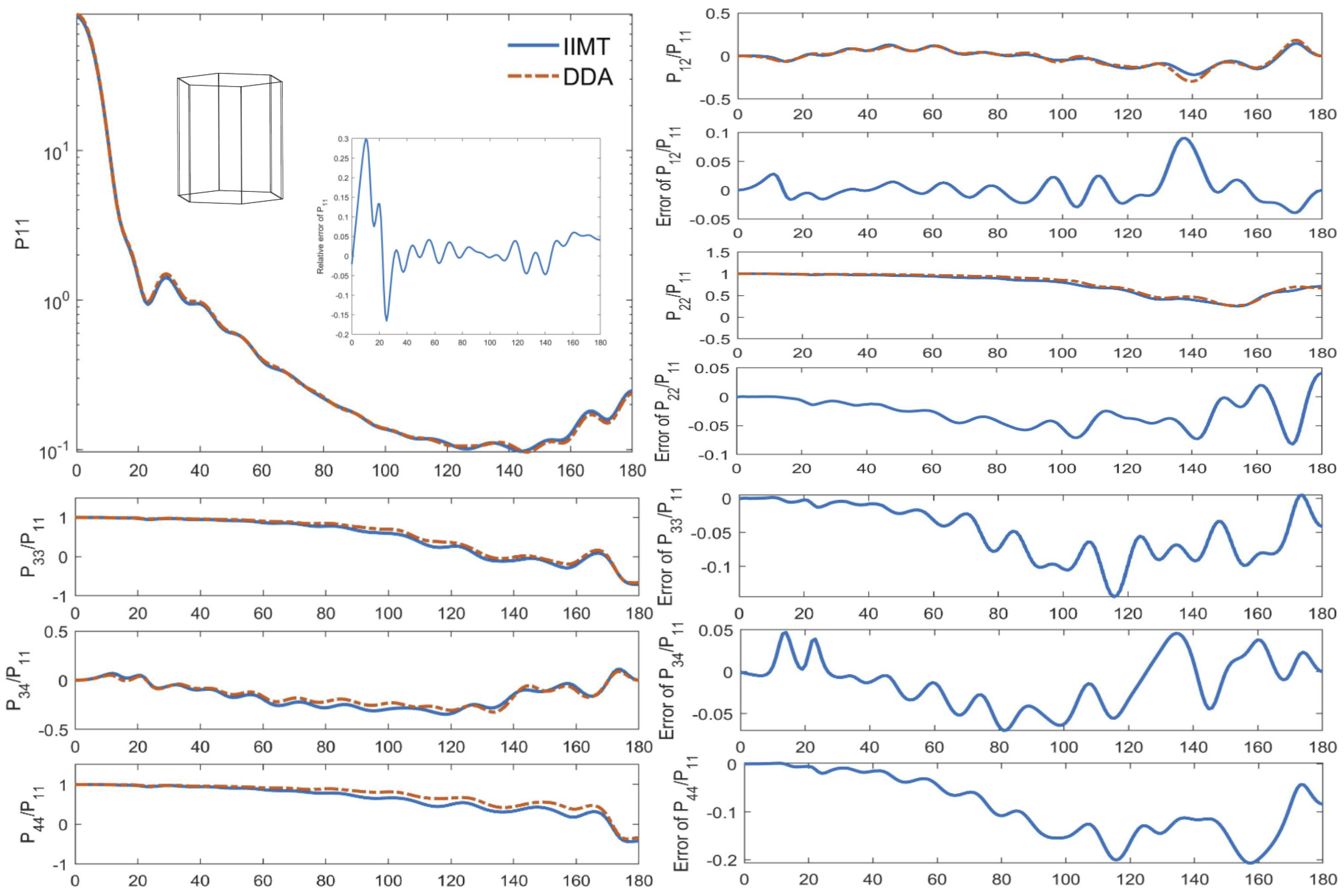
In the comparison of hexagonal prism particles, the wavelength of incident light was set as λ = 500 nm, the refractive index of the particles was taken as m = 1.33 + 0.0008 i, the bottom side length was set as a = 1.0 um and the height was set to be L = 2.0 um. The scattering phase matrix of the randomly oriented particles was simulated by IIM T-matrix and DDA methods, as illustrated in Figure 6. In the DDA model calculation, 2548 directions were selected to obtain the random-orientation averaged results.
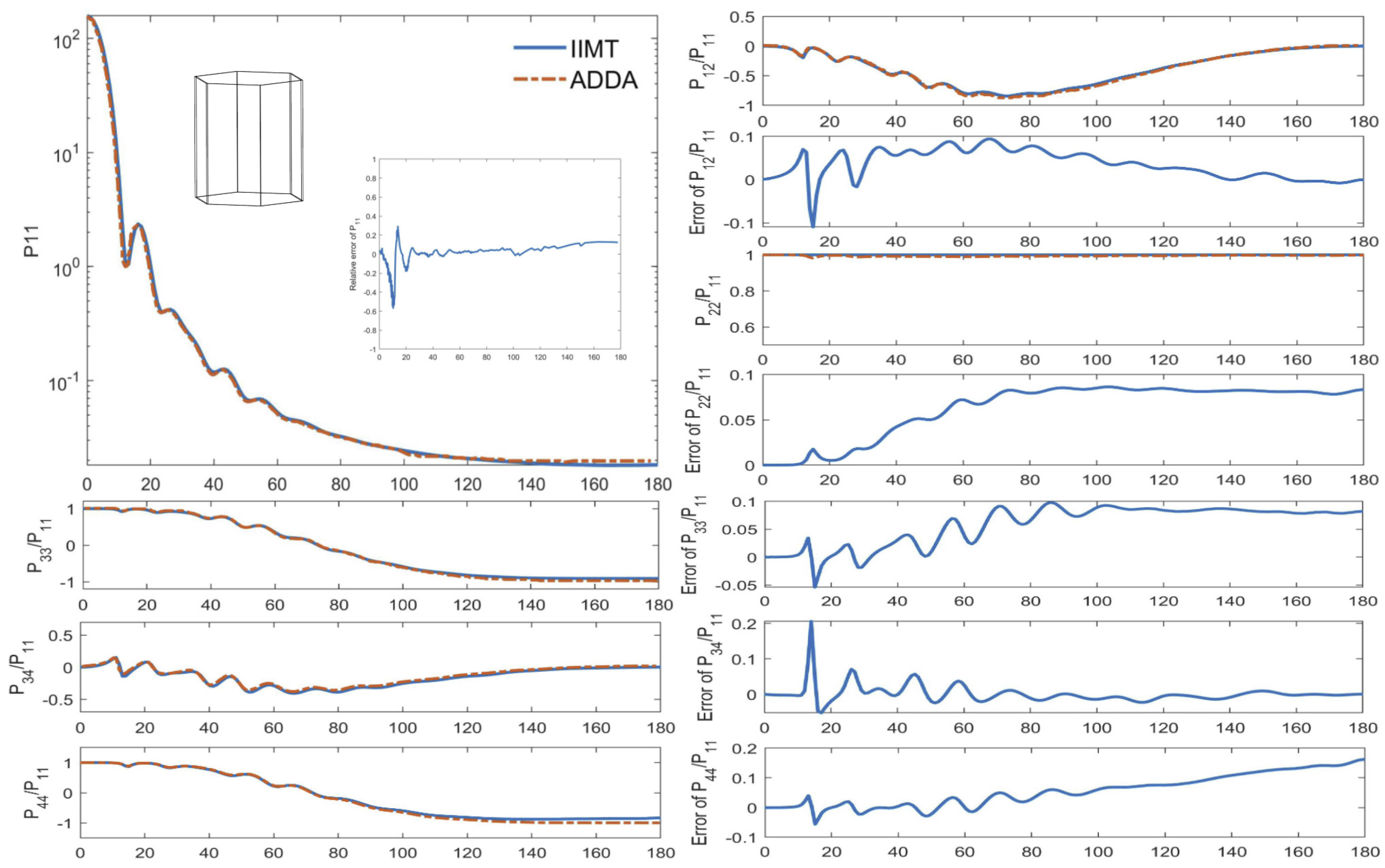
From the figure, it can be found that the simulation results of the IIM T-matrix model and the DDA model show a good consistency, where the P11 curves of the phase matrix elements obtained by the IIM T-matrix model and the DDA model almost coincided with each other. The curves of P12/P11 basically overlapped, and there was only a small error at 140°. When the scattering angle was 80°~110°, the P33/P11 and P34/P11 curves of the IIM T-matrix model were slightly lower than those of DDA model. The P22/P11 and P44/P11 curves of the IIM T-matrix model were generally lower than those of DDA.
The integral scattering properties were also compared in this paper, and the results are shown in Table 1. As can be seen, the relative errors of Cext (extinction section) and (scattering cross section) are less than 0.2%. The relative errors of Cabs (absorption cross section) are a little larger, reaching 7%.
The improved IIM T-matrix model was also validated for a hexagonal prism with a large refractive index. In this comparison, the refractive index of the particles was taken as m = 1.2762 + 0.4133 i and other parameters were unchanged. In the calculation of the ADDA model, 4097 orientation directions were used to obtain the average results (as illustrated in Figure 7). Additionally, the integral scattering properties were also compared, as shown in Table 2. The results show that there is a good consistency between two models. Especially in forward scattering directions, the deviations between the two models are much smaller. For P12/P11, in the scattering angle of 60°~90°, the IIM T-matrix model calculation result was slightly higher. The curves of P44/P11, P33/P11 and P34/P11 are basically consistent. The P22/P11 curve of the IIM T-matrix model was generally higher than that of ADDA. For the integral scattering parameters, the relative errors of Cext were less than 0.1% and the relative errors of Csca and Cabs were less than 0.6%.
(2)
Octagonal prism case
In the comparison of octagonal prism particles, the wavelength of incident light was set as λ = 1000 nm, the refractive index of the particles was taken as m = 1.33 + 0.0008 i, the bottom side length as set as a = 1.0 um and the height was set as L = 2.0 um. The scattering phase matrix of the randomly oriented particles was simulated using the IIM T-matrix method and DDA model, as illustrated in Figure 8. In DDA model calculation, 1690 orientation directions were selected to obtain the average results.
From the graph, it can be found that better agreement was achieved between the scattering phase matrix calculated by DDA and IIM T-matrix method. There was basically no difference between the P11 curves. For P12/P11, P33/P11 and P34/P11, the variation patterns of the deviations between the two models were similar to that of P11, and the absolute differences between the two models were within 0.05. The calculated results of small octagonal particles show higher consistency than those of the small hexagonal prism particle. For P22/P11 and P44/P11, in the scattering angle of 0°~140°, the absolute errors were within 0.02. The integral scattering properties are given in Table 3. The relative errors of Cext and Cabs were less than 0.1% and the relative errors of Csca were less than 0.5%.
(3)
Twelve prism case
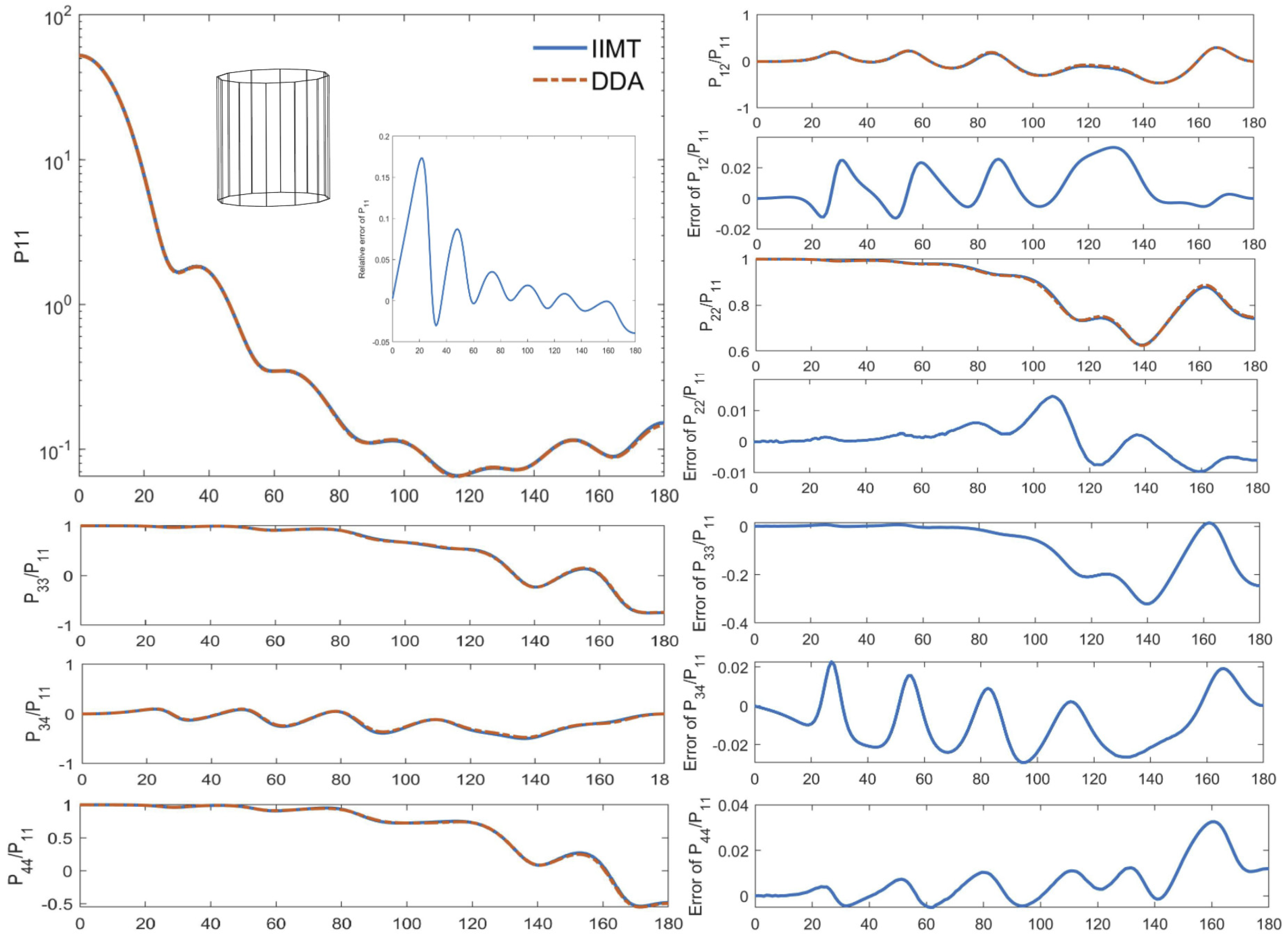
In the comparison of the twelve prism particles, the wavelength of incident light was set as λ = 1000 nm, the refractive index of the particles was taken as m = 1.33 + 0.0008 i, the bottom side length was set as a = 0.5 um and the height was L = 2.0 um. The scattering phase matrix of the randomly oriented particles was simulated using IIM T-matrix and DDA methods, as illustrated in Figure 9. In DDA model calculation, 1960 orientation directions were selected to obtain the average results.
The results show that good agreement was achieved between the IIM T-matrix model and DDA model, and their P11 curves completely coincided with each other. Additionally, the simulation errors of P12/P11, P33/P11 and P34/P11 were less than 0.02. It can be found that the calculation accuracy of twelve prism particles is higher than that of hexagonal and octagonal particles. For P22/P11, the absolute errors are generally within 0.01. For P44/P11, in the scattering angle of 0°~150°, the absolute errors are within 0.02. The integral scattering properties are given in Table 4. The relative errors of Cext and Csca are less than 0.06%. The relative errors of Cabs are less than 0.3%.
(4)
The comparison of the improved and traditional T-matrix method
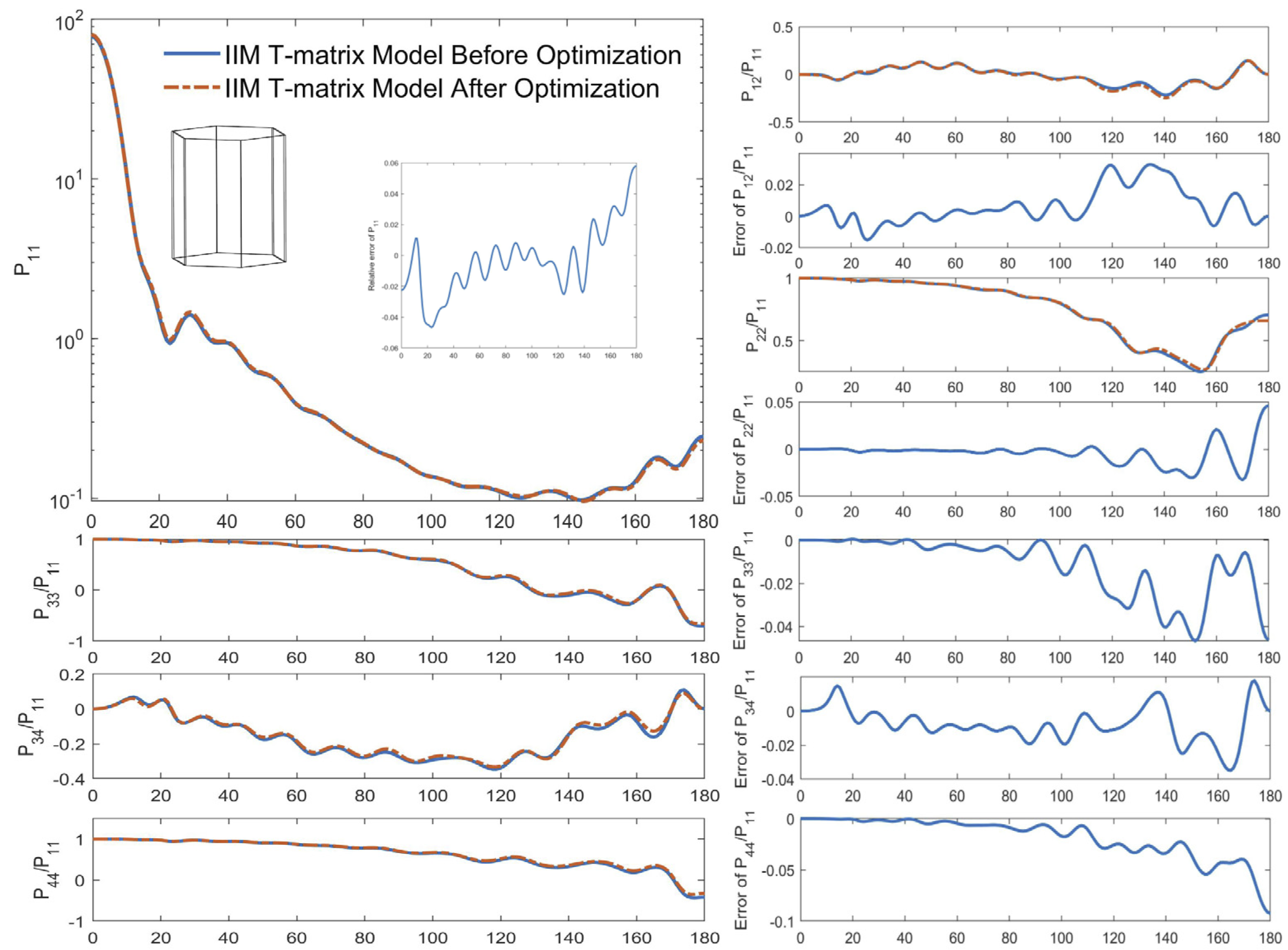
The differences in the calculation results of the T-matrix model before and after optimization were also compared. In this comparison, the particles used for model validation were hexagonal prism particles. The wavelength of incident light was set as λ = 500 nm, the refractive index of the particles was taken as m = 1.33 + 0.0008 i, the bottom side length was set as a = 1.0 um and the height was set to be L = 2.0 um. The scattering phase matrix of the randomly oriented particles was simulated by implementing IIM T-matrix methods before and after optimization, as illustrated in Figure 10, and the integral scattering parameters are presented in Table 5.
The results show that the consistency between the IIM T-matrix models before and after optimization was high. The relative errors of P11 were less than 0.1%. Additionally, the absolute errors of P12/P11, P33/P11 and P34/P11 were less than 0.03. For P22/P11, in the scattering angle of 0°~140°, the absolute errors were generally within 0.01. For P44/P11, in the scattering angle of 0°~140°, the absolute errors were within 0.05. The integral scattering properties also demonstrated good agreement, and the relative errors of Cext, Csca and Cabs were all less than 2%.

4.2. Large Particle Case

In this section, we compare the numerical results computed from the IIM T-matrix model and their counterparts computed using IGOA, where the particles used for model validation include the hexagonal prism particles and twelve prism particles.
In the comparison of hexagonal prism particles, the refractive index of the particles was taken as m = 1.3078 + 1.66 × 10⁻⁸ i, the size parameters were, respectively, set at 80 and 120 ( 2 π H / λ = 80 , 120 ) , and the ratio of the maximum distance between any two points on the base to the height of the prism was 1:1. (as illustrated in Figure 11). The halos emerged when the size parameter was 80, when the size parameter was 120, and the ice halo peaks become sharp. This proves that the IIM T-matrix model can well reflect the diffraction properties of large hexagonal prism particles. For P12/P11, P33/P11, P22/P11, P44/P11 and P34/P11, good agreement was also achieved between the results of the IIM T-matrix method and IGOA. The P12/P11 curves were basically coincident, but when the scattering angle was 60°~120°, for P33/P11 and P34/P11 curves, the calculation result of the IIM T-matrix model was slightly lower than that of IGOA.
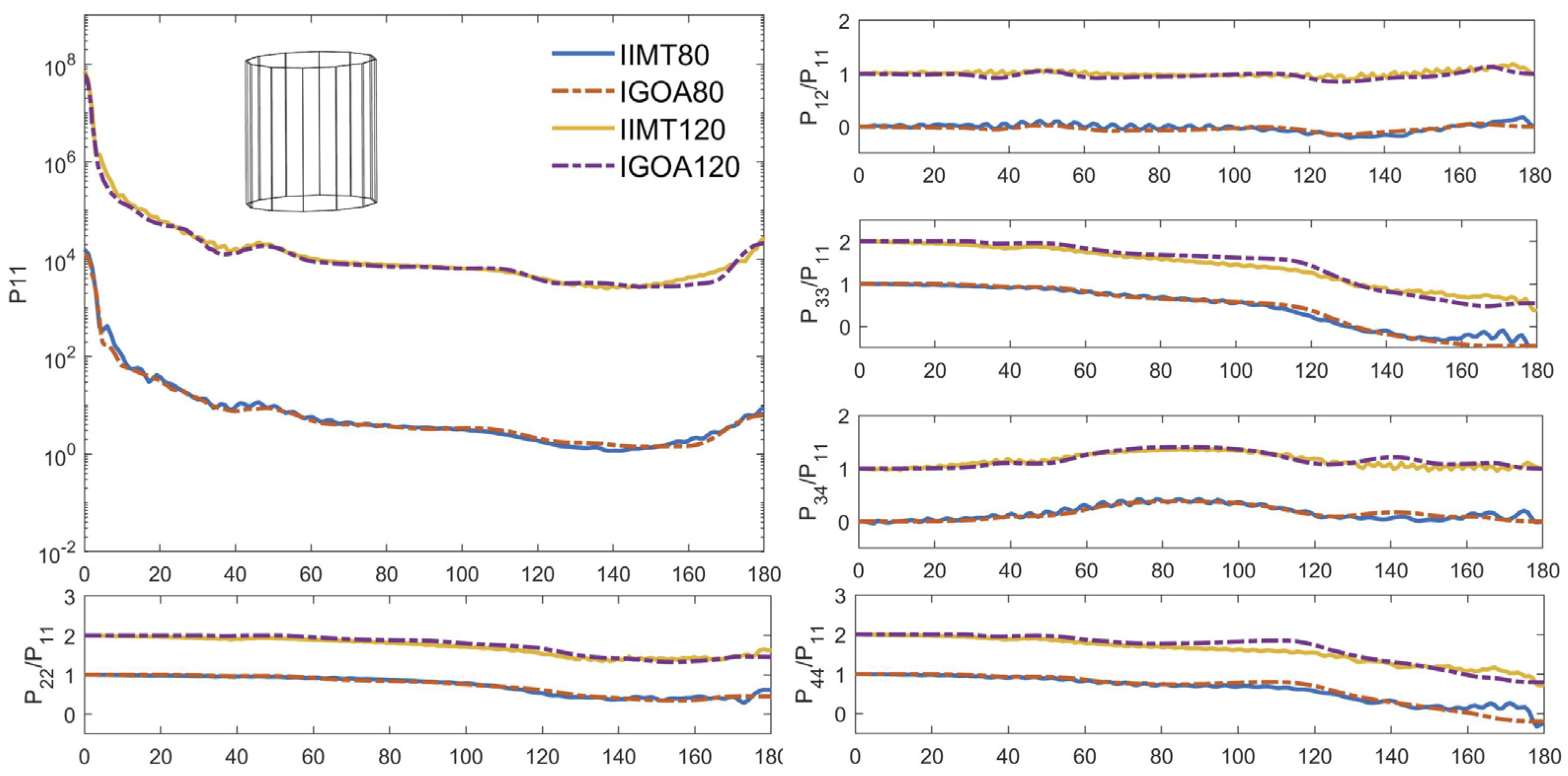
In the comparison of twelve prism particles, the refractive index of the particles was taken as m = 1.3078 + 1.66 × 10⁻⁸ i, the size parameters were, respectively .set at 80 and 120 ( 2 π H / λ = 80 , 120 ) , and the ratio of the maximum distance between any two points on the base to the height of the prism was 1:1 (as illustrated in Figure 12). From the results, it can be found that a good consistency was achieved between the results of IIM T-matrix method and IGOA. For P12/P11 and P22/P11, the two models displayed good consistency. For P33/P11, P44/P11 and P34/P11, in forward scattering directions, the deviations between the two models were small, but with the increased scattering angles, their differences increased gradually.

4.3. Calculation Efficiency by IIM T-Matrix Model before and after Optimization

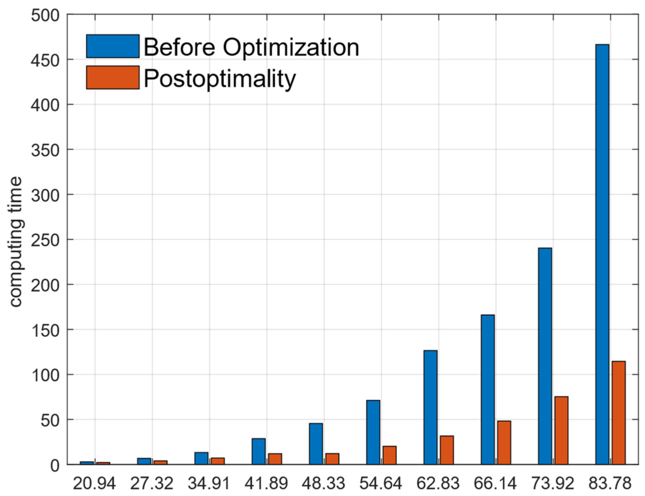
To validate the effectiveness of our improvements, the computational efficiency of the IIM T-matrix method was also evaluated. In this simulation, the refractive index was set to 1.33 + 0.0008 i, and the scatterers were set as hexagonal prism particles (with different size parameters). All the scattering processes were simulated on the same computer. Their computational time for the traditional and improved IIM T-matrix code is presented in Table 1. A histogram of their calculation time is shown in Figure 13.
As can be seen from Table 6, after being improved by the N-fold symmetric geometry, the computational efficiency of the IIM T-matrix model improved notably, especially for particles of a large size. When the size parameter reached 50, its calculation efficiency improved by more than 70%. From Figure 13, it can be seen that as the particle size increases, the improvement in the modeling efficiency becomes much more remarkable. This phenomenon can be explained by the increase in the computational amount of the U-matrix inversion processes. As the particle size becomes large, the dimensions of the U matrix increase dramatically, so the ratio of the computational amount of U-matrix inversion in the total computational task improves as well. From the results, it can be seen that the improved IIM T-matrix model has significant computational advantages for the calculation of large particles.

5. Discussion

The modeling accuracy of the IIM T-matrix method was validated by comparing its results with those of DDA, ADDA, IGOA and the IIM T-matrix method before optimization. In these comparisons, the relative errors of P11 were basically less than 5% where the forward scattering errors of the twelve small prism particles were less than 2%. The absolute errors of P12/P11, P33/P11, P22/P11, P44/P11 and P34/P11 were mostly less than 0.05, and some of them were less than 0.01. Relative errors of extinction cross section were basically less than 1% and the errors of scattering cross section and absorption cross section were less than 3%. Whether regarding the calculation of large particles or small particles, the twelve prisms have better accuracy. The reason is that with the increase in the side edges of prisms, the side surface becomes gradually smooth and closer to the cylindrical shape, and the computational accuracy of rotational symmetric particles is always better than other types of particles in most calculation models.
The computational time for the particles with different sizes was compared by using the traditional and improved IIM T-matrix model. In this comparison, the computational efficiency of the IIM T-matrix model improved notably, especially for particles with a large scale size. When the size parameter reaches 50, its calculation efficiency improves by more than 70%.

6. Conclusions

The IIM T-matrix model is regarded as one of the most promising models to simulate light scattering by atmospheric non-spherical particles. Compared with other computational models, e.g., DDA and PSTD, this model can not only compute the scattering parameters of randomly oriented particles analytically but also simulate them in much larger sizes effectively. However, because the IIM T-matrix model needs to be iterated layer by layer along the radial direction, the larger the particle size is, the more iterations are required. Therefore, ways to reduce the matrix computation represent an important research topic for the invariant imbedding T-matrix method. In this paper, an efficient realization scheme was proposed to improve the calculation efficiency of the IIM T-matrix method. Additionally, then the IIM T-matrix method’s modeling accuracy was validated by comparing its results with those of the DDA, ADDA and IGOA methods. The computing time of particles with different sizes was compared by using the traditional and improved IIM T-matrix model. Several conclusions were drawn and are as follows:
(1)
The improved IIM T-matrix method can accurately simulate the light scattering parameters of the particles with N-fold symmetry. The scattering properties obtained by the IIM T-matrix method demonstrated excellent agreement with those of the well-test scattering models, especially for the polarization characteristics of which absolute differences between our model and DDA were within 0.02.
(2)
The computational time of the model was notably shortened by nearly 50%. As the particle size increased, the improvement in the modeling efficiency was much more remarkable, reaching approximately 75% for large particles.

Author Contributions

Conceptualization, S.H.; methodology, S.H.; software, J.Z.; validation, X.L. and S.L.; formal analysis, J.Z.; investigation, J.Z.; resources, S.H.; data curation, J.Z.; writing—original draft preparation, J.Z.; writing—review and editing, S.H.; visualization, J.Z.; supervision, S.H.; project administration, S.H.; funding acquisition, S.H. All authors have read and agreed to the published version of the manuscript.

Funding

This research was supported by the National Natural Science Foundation of China (Grant 62105367 and 42175154) and the Hunan Provincial Natural Science Foundation of China (2020JJ4662).

Data Availability Statement

The data is obtained by DDA, IIMT and IGOA. The reader can calculate the corresponding data according to the parameters in the paper.

Conflicts of Interest

The authors declare no conflict of interest.

Appendix A

The calculation formula of the U matrix can be written as follows:
U ¯ ¯ m n m n ( r ) = r 2 Ω d Ω ( Y ¯ ¯ * m n ( θ , φ ) ) T u ( r ) Z ¯ ¯ ( r ) Y ¯ ¯ m n ( θ , φ )
It can be expressed in a more complete form as follows:
U ¯ ¯ m n m n ( r ) = k 2 r 2 ( 1 ) m + m [ 2 n + 1 4 π n ( n + 1 ) ] 1 / 2 [ 2 n + 1 4 π n ( n + 1 ) ] 1 / 2 0 2 π d φ 0 π d θ sin θ exp [ i ( m m ) φ ] [ ε r ( r , θ , φ ) 1 ] × π m n ( θ ) π m n ( θ ) + τ m n ( θ ) τ m n ( θ ) i [ π m n ( θ ) τ m n ( θ ) + τ m n ( θ ) π m n ( θ ) ] 0 i [ π m n ( θ ) τ m n ( θ ) + τ m n ( θ ) π m n ( θ ) ] π m n ( θ ) π m n ( θ ) + τ m n ( θ ) τ m n ( θ ) 0 0 0 n ( n + 1 ) n ( n + 1 ) d 0 m n d 0 m n ε r ( r , θ , φ )
As can be seen above, there are only three independent elements in the U matrix, they are U 11 , U 12 and U 33 , the expression of the three variables can be expressed as
U ¯ ¯ 11 m n m n ( r ) = a 0 π [ π m n ( θ ) π m n ( θ ) + τ m n ( θ ) τ m n ( θ ) ] sin θ 0 2 π exp [ i ( m m ) φ ] [ ε r ( r , θ , φ ) 1 ] d φ d θ
U ¯ ¯ 12 m n m n ( r ) = a 0 π i [ π m n ( θ ) τ m n ( θ ) + τ m n ( θ ) π m n ( θ ) ] sin θ 0 2 π exp [ i ( m m ) φ ] [ ε r ( r , θ , φ ) 1 ] d φ d θ
U ¯ ¯ 33 m n m n ( r ) = a 0 π n ( n + 1 ) n ( n + 1 ) d 0 m n d 0 m n sin θ 0 2 π exp [ i ( m m ) φ ] [ ε r ( r , θ , φ ) 1 ] ε r ( r , θ , φ ) d φ d θ
a = k 2 r 2 ( 1 ) m + m [ 2 n + 1 4 π n ( n + 1 ) ] 1 / 2 [ 2 n + 1 4 π n ( n + 1 ) ] 1 / 2
For the particles with N-fold symmetric geometry, their symmetry is related to azimuth φ , so we firstly extract the variables related to φ in Equation (A6) as
k m m ( θ ) = 0 2 π exp [ i ( m m ) φ ] [ ε r ( r , θ , φ ) 1 ] d φ
k ˜ m m ( θ ) = 0 2 π exp [ i ( m m ) φ ] [ ε r ( r , θ , φ ) 1 ] ε r ( r , θ , φ ) d φ
For the space outside the particle, the item is ε r ( r , θ , φ ) 1 = 0 , therefore we only need to consider the integral inside the particle in the integral above. According to the consideration, we can divide the integral of Equation (19) into the superposition of N integrals, which is written as follows:
0 2 π exp [ i ( m m ) φ ] [ ε r ( r , θ , φ ) 1 ] d φ = φ 1 φ 2 exp [ i ( m m ) φ ] [ ε r ( r , θ , φ ) 1 ] d φ + φ 1 + 2 π N φ 2 + 2 π N exp [ i ( m m ) φ ] [ ε r ( r , θ , φ ) 1 ] d φ + φ 1 + 2 π N ( N 1 ) φ 2 + 2 π N ( N 1 ) exp [ i ( m m ) φ ] [ ε r ( r , θ , φ ) 1 ] d φ = k = 0 N 1 φ 1 + 2 π N k φ 2 + 2 π N k exp [ i ( m m ) φ ] [ ε r ( r , θ , φ ) 1 ] d φ
For the homogeneous particle, [ ε r ( r , θ , φ ) 1 ] is a constant, so Equation (A9) can be expressed as follows:
k = 0 N 1 φ 1 + 2 π N k φ 2 + 2 π N k exp [ i ( m m ) φ ] [ ε r ( r , θ , φ ) 1 ] d φ = [ ε r ( r , θ , φ ) 1 ] k = 0 N 1 φ 1 + 2 π N k φ 2 + 2 π N k exp [ i ( m m ) φ ] d φ
In case that mm’, unifying the upper and lower bounds of the integrals in Equation (A10), then it can be expressed as
0 2 π exp [ i ( m m ) φ ] d φ = i ( m m ) k = 0 N 1 { exp [ i ( m m ) ( φ 2 + 2 π N k ) ] exp [ i ( m m ) ( φ 1 + 2 π N k ) ] } = i ( m m ) { exp [ i ( m m ) φ 2 ] exp [ i ( m m ) φ 1 ] } k = 0 N 1 exp [ i ( m m ) 2 π N k ]
By extracting exp [ i ( m m ) φ 2 + φ 1 2 ] from Equation (A11), we can obtain
0 2 π exp [ i ( m m ) φ ] d φ = i ( m m ) k = 0 N 1 exp [ i ( m m ) ( φ 2 + φ 1 2 ) ] exp [ i ( m m ) φ 2 φ 1 2 ] exp [ i ( m m ) φ 2 φ 1 2 ] k = 0 N 1 exp [ i ( m m ) 2 π N k ]
Using the Euler formula, the equation above can be rewritten as follows:
0 2 π exp [ i ( m m ) φ ] d φ = 2 ( m m ) k = 0 N 1 exp [ i ( m m ) ( φ 2 + φ 1 ) ] sin [ ( m m ) φ 2 φ 1 2 ] k = 0 N 1 exp [ i ( m m ) 2 π N k ]
According to the orthogonality of the triangular basis,
k = 0 N 1 exp [ i ( m m ) 2 π N k ] = 0 , | m m | N l , l = 1 , 2 , N , | m m | = N l , l = 1 , 2 ,
the entire integral of the azimuth φ is expressed as:
0 2 π exp [ i ( m m ) φ ] d φ = 2 N m m exp [ i ( m m ) φ 2 + φ 1 2 ] sin [ ( m m ) φ 2 φ 1 2 ] δ | m m | , N l
If we assume the azimuthal part as M ( θ ) , it can be expressed as
M ( θ ) = 2 N m m exp [ i ( m m ) φ 2 + φ 1 2 ] sin [ ( m m ) φ 2 + φ 1 2 ] δ | m m | , N l , | m m | 0 ; N ( φ 2 φ 1 ) , | m m | = 0 ;
Substitute the equation above into Equation (13), so the calculation formula of U matrix can be written as
U ¯ ¯ m n m n ( r ) = k 2 r 2 0 π sin θ [ ε ( r , θ , φ ) 1 ] W m n m n ( θ , φ ) M ( θ ) d θ
where
W m n m n ( θ , φ ) = π ˜ m n ( θ ) π ˜ m n ( θ ) + τ ˜ m n ( θ ) τ ˜ m n ( θ ) i [ π ˜ m n ( θ ) τ ˜ m n ( θ ) + τ ˜ m n ( θ ) π ˜ m n ( θ ) ] 0 i [ π ˜ m n ( θ ) τ ˜ m n ( θ ) + τ ˜ m n ( θ ) π ˜ m n ( θ ) ] π ˜ m n ( θ ) π ˜ m n ( θ ) + τ ˜ m n ( θ ) τ ˜ m n ( θ ) 0 0 0 d ˜ 0 m n ( θ ) d ˜ 0 m n ( θ ) ε

References

  1. Herman, M.; Deuzé, J.L.; Marchand, A.; Roger, B.; Lallart, P. Aerosol remote sensing from POLDER/ADEOS over the ocean: Improved retrieval using a nonspherical particle model. J. Geophys. Res. Atmos. 2005, 110, D10S02. [Google Scholar] [CrossRef]
  2. Evans, K.F.; Stephens, G.L. A new polarized atmospheric radiative transfer model. J. Quant. Spectrosc. Radiat. Transf. 1991, 46, 413–423. [Google Scholar] [CrossRef]
  3. Cheng, T.H.; Gu, X.F.; Yu, T.; Tian, G.L. The reflection and polarization properties of non-spherical aerosol particles. J. Quant. Spectrosc. Radiat. Transf. 2010, 111, 895–906. [Google Scholar] [CrossRef]
  4. Dubovik, O.; Sinyuk, A.; Lapyonok, T.; Holben, B.N.; Mishchenko, M.; Yang, P.; Eck, T.F.; Volten, H.; Muñoz, O.; Veihelmann, B.; et al. Application of spheroid models to account for aerosol particle nonsphericity in remote sensing of desert dust. J. Geophys. Res. Atmos. 2006, 111, D11208. [Google Scholar] [CrossRef]
  5. Yang, P.; Liou, K.-N.; Bi, L.; Liu, C.; Yi, B.; Baum, B.A. On the radiative properties of ice clouds: Light scattering, remote sensing, and radiation parameterization. Adv. Atmos. Sci. 2014, 32, 32–63. [Google Scholar] [CrossRef]
  6. Heinson, Y.W.; Maughan, J.B.; Ding, J.; Chakrabarti, A.; Yang, P.; Sorensen, C.M. Q-space analysis of light scattering by ice crystals. J. Quant. Spectrosc. Radiat. Transf. 2016, 185, 86–94. [Google Scholar] [CrossRef]
  7. Liou, K.N.; Takano, Y. Light scattering by nonspherical particles: Remote sensing and climatic implications. Atmos. Res. 1994, 31, 271–298. [Google Scholar] [CrossRef]
  8. Bi, L.; Lin, W.; Wang, Z.; Tang, X.; Zhang, X.; Yi, B. Optical Modeling of Sea Salt Aerosols: The Effects of Nonsphericity and Inhomogeneity. J. Geophys. Res. Atmos. 2018, 123, 543–558. [Google Scholar] [CrossRef]
  9. Waterman, P.C. Matrix formulation of electromagnetic scattering. Proc. IEEE 1965, 53, 805–812. [Google Scholar] [CrossRef]
  10. Mishchenko, M.I. Infrared absorption by shape distributions of NH3 ice particles: An application to the Jovian atmosphere. Earth Moon Planets 1991, 53, 149–156. [Google Scholar] [CrossRef]
  11. Hu, S. Research on the Numerical Computational Models and Application of the scattering Properties of Nonspherical Atmospheric Particles. Ph.D. Thesis, National University of Defense Technology, Changsha, China, 2018. [Google Scholar]
  12. Peterson, B.; Ström, S. T Matrix for Electromagnetic Scattering from an Arbitrary Number of Scatterers and Representations of E(3). Phys. Rev. D 1973, 8, 3661–3678. [Google Scholar] [CrossRef]
  13. Mishchenko, M.I.; Travis, L.D. T-matrix computations of light scattering by large spheroidal particles. Opt. Commun. 1994, 109, 16–21. [Google Scholar] [CrossRef]
  14. Wielaard, D.J.; Mishchenko, M.I.; Macke, A.; Carlson, B.E. Improved T-matrix computations for large, nonabsorbing and weakly absorbing nonspherical particles and comparison with geometrical-optics approximation. Appl. Opt. 1997, 36, 4305–4313. [Google Scholar] [CrossRef] [PubMed]
  15. Mishchenko, M.I.; Travis, L.D. Capabilities and limitations of a current FORTRAN implementation of the T-matrix method for randomly oriented, rotationally symmetric scatterers. J. Quant. Spectrosc. Radiat. Transf. 1998, 60, 309–324. [Google Scholar] [CrossRef]
  16. Havemann, S.; Baran, A.J. Extension of T-matrix to scattering of electromagnetic plane waves by non-axisymmetric dielectric particles: Application to hexagonal ice cylinders. J. Quant. Spectrosc. Radiat. Transf. 2001, 70, 139–158. [Google Scholar] [CrossRef]
  17. Schulz, F.M.; Stamnes, K.; Stamnes, J.J. Scattering of electromagnetic waves by spheroidal particles: A novel approach exploiting the T matrix computed in spheroidal coordinates. Appl. Opt. 1998, 37, 7875–7896. [Google Scholar] [CrossRef] [PubMed]
  18. Mackowski, D.W. Discrete dipole moment method for calculation of the T matrix for nonspherical particles. J. Opt. Soc. America. A Opt. Image Sci. Vis. 2002, 19, 881–893. [Google Scholar] [CrossRef]
  19. Loke, V.L.Y.; Nieminen, T.A.; Heckenberg, N.R.; Rubinsztein-Dunlop, H. T-matrix calculation via discrete dipole approximation, point matching and exploiting symmetry. J. Quant. Spectrosc. Radiat. Transf. 2009, 110, 1460–1471. [Google Scholar] [CrossRef]
  20. Johnson, B.R. Invariant imbedding T matrix approach to electromagnetic scattering. Appl. Opt. 1988, 27, 4861–4873. [Google Scholar] [CrossRef]
  21. Bi, L.; Yang, P.; Kattawar, G.W.; Mishchenko, M.I. A numerical combination of extended boundary condition method and invariant imbedding method applied to light scattering by large spheroids and cylinders. J. Quant. Spectrosc. Radiat. Transf. 2013, 123, 17–22. [Google Scholar] [CrossRef]
  22. Bi, L.; Yang, P.; Kattawar, G.W.; Mishchenko, M.I. Efficient implementation of the invariant imbedding T-matrix method and the separation of variables method applied to large nonspherical inhomogeneous particles. J. Quant. Spectrosc. Radiat. Transf. 2013, 116, 169–183. [Google Scholar] [CrossRef]
  23. Bi, L.; Yang, P. Accurate simulation of the optical properties of atmospheric ice crystals with the invariant imbedding T-matrix method. J. Quant. Spectrosc. Radiat. Transf. 2014, 138, 17–35. [Google Scholar] [CrossRef]
  24. Hu, S.; Liu, L.; Zeng, Q.; Gao, T.; Zhang, F. An investigation of the symmetrical properties in the invariant imbedding T-matrix method for the nonspherical particles with symmetrical geometry. J. Quant. Spectrosc. Radiat. Transf. 2021, 259, 107401. [Google Scholar] [CrossRef]
  25. Hu, S.; Liu, L.; Zeng, Q.; Gao, T.; Zhang, F.; Liu, X. Efficient design of the realization scheme of the Invariant Imbedding (IIM) T-matrix light scattering model for atmospheric nonspherical particles. J. Quant. Spectrosc. Radiat. Transf. 2020, 251, 106999. [Google Scholar] [CrossRef]
  26. Hu, S.; Liu, L.; Gao, T.; Zeng, Q.; Liu, X. An efficient implementation of the light scattering simulation for random-oriented non-rotationally symmetric particles using invariant imbedding T-matrix method. J. Quant. Spectrosc. Radiat. Transf. 2020, 241, 106734. [Google Scholar] [CrossRef]
  27. Sun, B.; Yang, P.; Kattawar, G.W. Many-body iterative T-matrix method for large aspect ratio particles. J. Quant. Spectrosc. Radiat. Transf. 2013, 127, 165–175. [Google Scholar] [CrossRef]
  28. Doicu, A.; Wriedt, T.; Khebbache, N. An overview of the methods for deriving recurrence relations for T-matrix calculation. J. Quant. Spectrosc. Radiat. Transf. 2019, 224, 289–302. [Google Scholar] [CrossRef]
  29. Schulz, F.M.; Stamnes, K.; Stamnes, J.J. Point-group symmetries in electromagnetic scattering. J. JOSA A 1999, 16, 853–865. [Google Scholar] [CrossRef]
  30. Mishchenko, M.I. Light scattering by randomly oriented axially symmetric particles. JOSA A 1991, 8, 871–882. [Google Scholar] [CrossRef]
  31. Doicu, A.; Wriedt, T. The Invariant Imbedding T Matrix Approach. In The Generalized Multipole Technique for Light Scattering: Recent Developments; Wriedt, T., Eremin, Y., Eds.; Springer International Publishing: Cham, Switzerland, 2018; pp. 35–47. [Google Scholar]
Figure 1. Cross section diagram of non-spherical particles. In the figure, R1 is the maximum inscribed sphere radius and R2 is the minimum circumscribed sphere radius.
Remotesensing 14 04061 g001
Figure 2. The particles with N-fold symmetric geometry.
Remotesensing 14 04061 g002
Figure 3. Particles with N-fold symmetric geometry cross section. φ r is the rotation period angle (for the particles with N-fold symmetric geometry, φ r = 2 π / N ), θ is the zenith angle. φ 1 , φ 2 is the azimuth of the intersection point in [ φ r / 2 , φ r / 2 ] .
Remotesensing 14 04061 g003
Figure 4. The layout of the matrix element of U matrix. Because of the symmetrical properties of U matrix, it can be rearranged as a block diagonal matrix with N blocks. Different colors correspond to different azimuth mode “ m ”, brown indicates m = i, red and green indicate increase and decrease on this basis respectively.
Remotesensing 14 04061 g004
Figure 5. The layout of the matrix element of g-matrix. It is rearranged as a block diagonal matrix with N blocks referring to the structure of the U matrix. Different colors correspond to different azimuth mode “m”, brown indicates m = i, red and green indicate increase and decrease on this basis respectively.
Remotesensing 14 04061 g005
Figure 6. The phase matrices and their errors calculated by the IIM T−matrix and DDA methods for small hexagonal prism particles with random orientations. The abscissa is the scattering angle. The solid line is the IIM T−matrix model and the dashed is DDA model. The errors of P12/P11, P22/P11, P33/P11, P34/P11 and P44/P11 are absolute errors.
Remotesensing 14 04061 g006
Figure 7. The phase matrices and their errors calculated by the IIM T−matrix method and ADDA methods for small hexagonal prism particles with random orientations. The abscissa is the scattering angle. The solid line is the IIM T−matrix method and the dashed is ADDA model. The errors of P12/P11, P22/P11, P33/P11, P34/P11 and P44/P11 are absolute errors.
Remotesensing 14 04061 g007
Figure 8. The phase matrices and their errors calculated by the IIM T−matrix and DDA methods for small octagonal prism particles with random orientations. The abscissa is the scattering angle. The solid line is the IIM T−matrix model and the dashed is DDA model.
Remotesensing 14 04061 g008
Figure 9. The phase matrices and their errors calculated by the IIM T−matrix and DDA methods for small twelve prism particles with random orientations. The abscissa is the scattering angle. The solid line is the IIM T−matrix model and the dashed is DDA model. The errors of P12/P11, P22/P11, P33/P11, P34/P11 and P44/P11 are absolute errors.
Remotesensing 14 04061 g009
Figure 10. The phase matrices and their errors calculated by the IIM T−matrix models before and after optimization of small hexagonal prism particles with random orientations. The abscissa is the scattering angle. The solid line is the IIM T−matrix model before optimization and the dashed is the IIM T−matrix model after optimization. The errors of P12/P11, P22/P11, P33/P11, P34/P11 and P44/P11 are absolute errors.
Remotesensing 14 04061 g010
Figure 11. Comparison of four phase matrix elements computed from the IGOA and the II−TM for hexagonal prism particles. The particle size parameters for curve pairs from lower to upper are 80, 120. For clarity, the phase functions of 120 are multiplied by 1000, P12/P11, P22/P11, P33/P11, P44/P11 and P34/P11 of 120 are shifted by 1. The solid line is the IIM T-matrix model and the dashed is IGOA model.
Remotesensing 14 04061 g011
Figure 12. Comparison of four phase matrix elements computed from the IGOA and the II-TM for twelve prism particles. The particle size parameters for curve pairs from lower to upper are 80, 120. For clarity, the phase functions of 120 are multiplied by 1000, P12/P11, P22/P11, P33/P11, P44/P11 and P34/P11 of 120 are shifted by 1. The solid line is the IIM T-matrix model and the dashed is IGOA model.
Remotesensing 14 04061 g012
Figure 13. Comparison of calculation efficiency before and after improving, the abscissa is the size parameter, and the ordinate is the calculation time.
Remotesensing 14 04061 g013
Table 1. The integral scattering properties of the hexagonal prism particles calculated by IIM T-matrix and DDA methods.
IIM T-MatrixDDARelative Errors/%
Cext/um2 8.59408.60970.1820
Csca/um2 8.43138.43480.0419
Cabs/um2 0.16270.17517.6205
Table 2. The integral scattering properties of the hexagonal prism particles calculated by IIM T matrix and ADDA methods.
IIM T-MatrixADDARelative Errors/%
Cext/um28.81008.81680.0770
Csca/um24.39034.41340.5252
Cabs/um24.41974.40360.3640
Table 3. The integral scattering properties of the octagonal prism particles calculated by IIM T-matrix and DDA methods.
IIM T-MatrixDDARelative Errors/%
Cext/um219.860319.87240.0607
Csca/um219.722819.73430.4366
Cabs/um20.13750.138160.0582
Table 4. The integral scattering properties of the twelve prism particles calculated by IIM T-matrix and DDA methods.
IIM T-MatrixDDARelative Errors/%
Cext/um214.363314.37040.0500
Csca/um214.272014.27900.0486
Cabs/um20.091230.091440.2298
Table 5. The integral scattering properties of the hexagonal prism particles calculated by IIM T-matrix models before and after optimization.
IIM T-Matrix before OptimizationIIM T-Matrix after OptimizationRelative Errors/%
Cext/um28.48438.59401.2771
Csca/um28.32448.43131.2675
Cabs/um20.15980.16271.7748
Table 6. Calculation time before and after optimization of hexagonal prism particle IIM T-matrix model.
Dimensional
Parameters
Calculation Time
T0 for Traditional
IIM T-Matrix/min
Calculation Time
T1 for the Improved
IIM T-Matrix/min
(T0 − T1)/T0 × 100%
20.942.972.2324.16%
27.326.784.0240.86%
34.9113.287.1746.48%
41.8928.7311.9558.06%
48.3345.5312.1273.89%
54.6471.1820.2371.76%
62.83126.5531.7074.51%
66.14166.0748.2870.25%
73.92240.3875.3568.54%
83.78466.43114.5875.35%
Publisher’s Note: MDPI stays neutral with regard to jurisdictional claims in published maps and institutional affiliations.