Article

A Novel Frequency-Domain Focusing Method for Geosynchronous Low-Earth-Orbit Bistatic SAR in Sliding-Spotlight Mode

1
School of Information and Communication Engineering, University of Electronic Science and Technology of China, Chengdu 611731, China
2
Institute of Remote-Sensing Satellite, China Academy of Space Technology, Beijing 100094, China
*
Author to whom correspondence should be addressed.
Remote Sens. 2022, 14(13), 3178; https://doi.org/10.3390/rs14133178
Submission received: 27 April 2022 / Revised: 13 June 2022 / Accepted: 17 June 2022 / Published: 1 July 2022

Abstract

:
The low-earth-orbit synthetic aperture radar (SAR) can achieve enhanced remote-sensing capabilities by exploiting the large-scale and long-duration beam coverage of a geosynchronous (GEO) SAR illuminator. Different bistatic imaging modes can be implemented by the steering of an antenna beam onboard the LEO receiver, such as high-resolution sliding-spotlight mode. In this paper, the accurate focusing of GEO-LEO bistatic SAR (GEO-LEO BiSAR) in sliding-spotlight mode is investigated. First, the two major problems of the accurate bistatic range model, i.e., curved trajectory within long integration time and ‘stop-and-go’ assumption error, for sliding-spotlight GEO-LEO BiSAR are analyzed. Then, a novel bistatic range model based on equivalent circular orbit trajectory is proposed to accurately represent the range history of GEO-LEO BiSAR in sliding-spotlight mode. Based on the proposed range model, a frequency-domain imaging method is put forward. First, a modified two-step preprocessing method is implemented to remove the Doppler aliasing caused by azimuth variance of Doppler centroid and beam steering. Then, an azimuth trajectory scaling is formulated to remove the azimuth variance of motion parameters due to curved trajectory. A modified frequency-domain imaging method is derived to eliminate the 2-D spatial variance and achieve accurate focusing of the echo data. Finally, imaging results and analysis on both simulated data and real data from an equivalent BiSAR experiment validate the effectiveness of the proposed method.

1. Introduction

Synthetic aperture radar (SAR) has proven to be an indispensable sensor both in civil and military applications, which has been extensively studied in recent decades [1,2,3,4]. Among different types of SAR system, geosynchronous SAR (GEO-SAR) can provide wide-area remote-sensing images with short revisit cycle, which has promising potential for advanced Earth observation missions [5]. Approximately one third of the Earth’s surface can be imaged with fine spatial resolution and one-day revisit cycle [6]. Over recent decades, various aspects of GEO-SAR have been extensively investigated, including system and performance analysis [7,8,9,10], mission design [11,12], imaging algorithms [13,14,15,16] and ionosphere/atmospheric effects and compensation [17,18,19].
In recent years, extensive works have been devoted to bistatic SAR system with GEO-SAR illuminator [20,21]. In [6], the GEO-BiSAR system with airborne receiver (GEO-SA-BiSAR) was investigated, where the imaging performance and mission design were analyzed in detail. In [22], the azimuth aliasing characteristics of GEO-SA-BiSAR were analyzed and multichannel reconstruction technique was applied to suppress the ambiguity. Thereafter, the imaging method [23,24] and moving target imaging [25,26] of GEO-SA-BiSAR were further studied.
On the other hand, the concept of GEO-LEO bi/multistatic SAR was analyzed in [27,28,29,30], where multiple LEO satellites received the backscattered signal of GEO-SAR and achieved bi/multistatic SAR imaging. Enhanced spatial resolution and radiometric performance was achieved by GEO-LEO BiSAR. The receiving system onboard the LEO satellite can be designed with low cost and light weight [31,32], which is favorable for the deployment of the LEO satellite constellation. In [33], a statistical model was proposed to evaluate the impact of the signal backscattered by LEO-SAR with a geostationary receiver, which can be used when designing the acquisition plan of the system. In [32], a constellation of geostationary-LEO multistatic SAR systems with LEO satellites working in transponding mode, named ConGaLSAR, was established. A typical ConGaLSAR system consisting of one geostationary SAR illuminator and 24 LEO transponders was put forward, which can achieve 3 m spatial resolution with 92.4 min revisit cycle. The ambiguity suppression for the constellation of GEO-LEO multistatic SAR was then analyzed in [34]. In addition, the azimuth multichannel signal reconstruction for ground moving target indication in GEO-LEO BiSAR system was studied in [35,36,37].
Due to the special configuration and echo characteristic, several imaging methods have been proposed for GEO-BiSAR [23,38,39,40]. In [41], a weighted back-projection algorithm was proposed to deal with the azimuth nonuniform sampling for azimuth multichannel GEO-LEO BiSAR imaging. However, this method can only be used in a multichannel receiving system, and the computational complexity is quite high, which limits its application in sliding-spotlight GEO-LEO BiSAR. In [42], a ‘non-stop-and-go’ range model (NSGRM) for GEO-LEO BiSAR was put forward, which employs second-order and fourth-order polynomial range models for GEO transmitter and LEO receiver, respectively. An imaging method based on multireceiving and compressed sensing was then proposed. In [24], the echo characteristic of GEO-SA-BiSAR was first analyzed, and a frequency-domain imaging method using a range model based on one stationary equivalence (RMOSE) was proposed. However, the current range models and imaging methods for GEO-BiSAR generally introduce significant error during long integration time, which cannot be used for GEO-LEO BiSAR imaging in sliding-spotlight mode.
The sliding-spotlight mode provides a valuable trade-off between resolution and azimuth swath-width using beam steering compared with stripmap mode and staring spotlight mode [43,44,45]. Plenty of imaging algorithms have been developed for high-resolution sliding-spotlight SAR data processing [46,47,48,49]. In [50], a modified equivalent squint range model (MESRM) was proposed for high-resolution spaceborne SAR, where a quadratic polynomial is employed to represent the curved trajectory of the LEO satellite. In [51], an equivalent acceleration range model (EARM) was proposed for sliding-spotlight mode, followed by a velocity-scaling imaging algorithm. The squinted sliding-spotlight SAR data focusing was studied in [52] and a processing scheme using 2-D baseband azimuth scaling was put forward. However, these range models and imaging methods are proposed for monostatic spaceborne SAR, which cannot be applied to GEO-LEO BiSAR in sliding-spotlight mode.
Based on the above analysis, the current range models and imaging methods for GEO-BiSAR and monostatic sliding-spotlight SAR cannot be applied to GEO-LEO BiSAR imaging in sliding-spotlight mode. Therefore, this article is the first attempt to address the main issues in sliding-spotlight GEO-LEO BiSAR and therefore proposes a novel frequency-domain imaging method. The main contributions and novelty of this paper can be summarized as follows.
  • A novel equivalent bistatic range model based on circular orbit trajectory ESRM, namely BiCoT-ESRM, is proposed to accurately represent the range history of GEO-LEO BiSAR in sliding-spotlight mode. BiCoT-ESRM comprehensively considers the two major problems, i.e., curved trajectory of LEO receiver and ‘stop-and-go’ assumption error.
  • Based on BiCoT-ESRM, the precise 2-D spectrum is derived, and a frequency-domain imaging method is put forward to achieve accurate focusing for sliding-spotlight GEO-LEO BiSAR.
  • The modified azimuth preprocessing can remove the total Doppler aliasing caused by spatial variance of Doppler centroid and beam steering in sliding-spotlight GEO-LEO BiSAR. Moreover, the azimuth variance of motion parameters due to curved trajectory can be simultaneously eliminated by the proposed azimuth trajectory scaling (ATS).
  • This experiment provides a new approach for designing the equivalent experiments to verify the theoretical studies and imaging methods related to GEO monostatic/bistatic SAR, which can be a worthwhile reference for researchers engaged in relevant studies.
The rest of the paper is organized as follows. Section 2 formulates the equivalent range model for GEO-LEO BiSAR in sliding-spotlight mode. Section 3 provides the detailed derivations of the proposed frequency-domain imaging method. In Section 4, simulation and real data-processing results are given to verify the effectiveness of the proposed method. Conclusions are finally drawn in Section 5.

2. Equivalent Range Model for GEO-LEO BiSAR

2.1. Imaging Geometry and Signal Model

The GEO-LEO BiSAR system uses geosynchronous SAR as the illuminator, which can provide wide beam coverage on the Earth’s surface. The LEO receiver can choose an interested target scene within the illuminated area and exploit various imaging modes for different observation purposes, e.g., sliding-spotlight and terrain observation by progressive scans (TOPS).
In Figure 1, the imaging geometry of GEO-LEO BiSAR in reference target local coordinate system (RTLC) [6] is illustrated. The potential imaging area is supposed to be illuminated by the GEO-SAR. The LEO receiver travels from A to C in orbital trajectory along the y-axis and works in sliding-spotlight mode. P is an arbitrary target located in the imaging scene. R T 0 and R R 0 are the instantaneous slant ranges from P to the transmitter and the receiver at beam center crossing time, respectively. θ s is the squint angle of the LEO receiver at the beam center crossing time.
Assuming the signal transmitted by the GEO-SAR is a linear frequency modulation pulse, the received signal after demodulation is then given by
S r t , τ = ω r τ R b i t c ω a t t 0 T a × exp j π k r τ R b i t c 2 j 2 π f 0 R b i t c
where t and τ represent the slow time and fast time variables, respectively. ω r and ω a are the range and azimuth envelopes, respectively. f 0 denotes the carrier frequency and c is the speed of light. T a represents the synthetic aperture time and k r is the range chirp rate. t 0 is the beam center crossing time of an arbitrary target P. R b i ( t ) is the bistatic range history, which will be analyzed in the next subsection in detail.

2.2. Range Model Analysis for GEO-LEO BiSAR without ‘stop-and-go’ Assumption

In this section, we derive the accurate range model for GEO-LEO BiSAR, which is indispensable for the later imaging method formulation. Two major problems will be encountered to accurately model the range history of GEO-LEO BiSAR in sliding-spotlight mode. First, the synthetic aperture time in sliding-spotlight mode is long and the error introduced by the curved trajectory of the LEO receiver cannot be ignored. Second, due to the large observation distance of the GEO transmitter, the commonly adopted ‘stop-and-go’ assumption would introduce significant error and should be accounted for.
In the past decade, several range models have been proposed to describe the relative motion between LEO-SAR and the target. The conventional hyperbolic range equation [53,54] approximates the motion trajectory A B of the LEO-SAR as a uniform linear motion, which leads to significant range error in high-resolution modes. In order to improve the precision of the conventional hyperbolic range equation, uniformly accelerated linear motion with equivalent radar acceleration is introduced to approximate the circular arc A B in Figure 1, which is the approach adopted by MESRM [50], EARM [51] and squinted-EARM [46]. However, the traditional range models for LEO-SAR did not exploit the essential characteristics of its circular orbital motion, which fail to accurately describe the actual motion trajectory of the LEO satellite with long integration time. In this paper, a novel equivalent squinted range model based on circular orbit trajectory (CoT-ESRM) is proposed to accurately represent the range history of the LEO receiver for GEO-LEO BiSAR in sliding-spotlight mode. In Figure 1, assume that the arc A B is part of an equivalent circular orbit of LEO-SAR (for elliptical orbit, A B can be approximated by a circular arc within a short period). Let R s and ω s denote the radius and angular velocity of the equivalent circular orbit in RTLC, respectively. Then, the length of the chord A B , i.e., the straight-line segment from A to B, can be calculated as
L c h o r d = 2 sin ω s t 2 R s
where ω s t represents the central angle of the arc A B with respect to the center of the equivalent circular orbit of LEO receiver. Therefore, the instantaneous slant range from the receiver position B to an arbitrary target P can be formulated by exploiting the triangle A B P as
R R t = R R 0 2 + L c h o r d 2 2 R R 0 L c h o r d sin θ s .
L c h o r d essentially contains higher-order components of azimuth time t and can better approximate the actual motion trajectory of LEO-SAR. In contrast, L c h o r d is replaced by v 0 t in the case of conventional hyperbolic range equation, and a quadratic polynomial v 0 t + A 0 t 2 / 2 for MESRM [50], EARM [51] and squinted-EARM [46], where v 0 and A 0 are the equivalent radar velocity and acceleration, respectively. It should be noted that R s and ω s can be calculated by letting the expanding coefficients of (3) equal those of the fourth-order polynomial expansion of range history.
As for the GEO transmitter, a fourth-order polynomial range model [55] is adopted to accurately represent its relative motion
R T t = R T 0 + k T 1 t + k T 2 t 2 + k T 3 t 3 + k T 4 t 4
where k T i , i = 1 , 2 , , 4 are the expanding coefficients of the GEO-SAR range model.
Next, we will analyze the error of ‘stop-and-go’ assumption in GEO-LEO BiSAR and therefore propose an accurate range model for GEO-LEO BiSAR without ‘stop-and-go’ assumption.
The propagation paths of GEO-LEO BiSAR are illustrated in Figure 2. Assume that the signal is transmitted at time instant t + τ . The time needed for the signal to travel from the transmitting position to the target P and then back to the receiving position are denoted as τ 1 and τ 2 , respectively. Then, the total time delay without ‘stop-and-go’ assumption is given by τ d = τ 1 + τ 2 . Therefore, the real range history of GEO-LEO BiSAR can be expressed as
R b i t , τ = c τ d = R T t + τ + R R t + τ + τ d .
R R t + τ + τ d can be approximated as a fourth-order polynomial as follows
R R t s + τ d R R 0 + k R 1 t s + τ d + k R 2 t s + τ d 2 + k R 3 t s + τ d 3 + k R 4 t s + τ d 4
where t s = t + τ denotes the transmitting time instant. k R i , i = 1 , 2 , , 4 are the expanding coefficients of the receiver range model in (3). Expanding (6) into Taylor series of τ d and substituting the results into (5) yields
c τ d = R T t s + R R t s + a 1 τ d + a 2 τ d 2 + a 3 τ d 3 + k R 4 τ d 4
where a 1 , a 2 and a 3 are the expanding coefficients given in the Appendix A. In order to obtain an approximate explicit solution with adequate precision, the third- and fourth-order terms of τ d are generally small and can be ignored herein to strike a balance between computational complexity and precision. Therefore, τ d can be obtained by solving the resulting quadratic equation of (7) as
τ d t s = c a 1 a 1 c 2 4 a 2 R T t s + R R t s 2 a 2 .
Please note that in (8), τ d is related to t and τ . As analyzed in [32], the phase error caused by ‘stop-and-go’ assumption within pulse duration are less than π / 4 and can generally be ignored for GEO-LEO BiSAR. Hence, the fast time variable τ in (8) can be eliminated, yielding the delay τ d t independent of τ .
Based on the above high-precision bistatic delay in (8), the range error caused by ‘stop-and-go’ assumption can be expressed as a fourth-order polynomial of t
Δ R S A G e r r t = c τ d t R T t + R R t Δ R b i + Δ k 1 t + Δ k 2 t 2 + Δ k 3 t 3 + Δ k 4 t 4 .
Therefore, the range model of GEO-LEO BiSAR can be expressed as
R b i t = R T t + R R t + Δ R S A G e r r t = R T 0 s + k T 1 s t + k T 2 s t 2 + k T 3 s t 3 + k T 4 s t 4 + R R 0 2 + 2 sin ω s t 2 R s 2 4 R R 0 sin ω s t 2 R s sin θ s
where R T 0 s = R T 0 + Δ R b i . k T i s = k T i + Δ k i , i = 1 , 2 , 3 , 4 are the sum of the i-th order coefficients of the GEO transmitter and the ‘stop-and-go’ range error in (9).

2.3. Equivalent Range Model for GEO-LEO BiSAR

Inspecting (10), the bistatic range R b i ( t ) is the sum of a fourth-order polynomial and a square-root term, which is difficult to obtain an explicit expression of the 2-D spectrum using principle of stationary phase. Therefore, in this section, an equivalent bistatic range model based on CoT-ESRM (BiCoT-ESRM) is proposed to accurately represent the range history of GEO-LEO BiSAR in sliding-spotlight mode, which is given by
R b i E q t = R T 0 s + k T 4 s + Δ k e r r 4 t 4 + R R 0 2 + 2 sin ω e t 2 R e 2 4 R R 0 sin ω e t 2 R e sin θ e
where ω e , R e and θ e are the bistatic equivalent parameters, which can be obtained by letting the first-, second- and third-order expanding coefficients of (11) equal to those of (10). The detailed derivations of ω e , R e and θ e are given in the Appendix A.2. Δ k e r r 4 is the coefficient of a fourth-order term to compensate for the residual fourth-order range error, which can be calculated by the difference between the fourth-order expanding coefficients of the square-root term of (10) and that of (11).
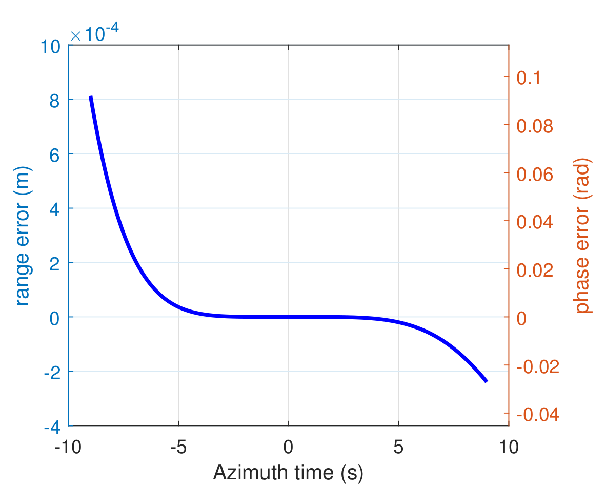
The bistatic range error introduced by BiCoT-ESRM for GEO-LEO BiSAR within 18 s azimuth time is illustrated in Figure 3 and Figure 4, where two state-of-the-art range models for GEO bistatic SAR are investigated for comparison, including the NSGRM in [32] and RMOSE in [24]. The simulation parameters are given in Table 1. Please note that the original RMOSE does not take into account the ‘stop-and-go’ assumption error, which will bring significant error. In this comparison, we implement a modified version of RMOSE by deriving the ‘non-stop-and-go’ delay of RMOSE based on the method in this paper. It can be observed from Figure 4 that the maximum bistatic range error of BiCoT-ESRM is approximately 8 × 10 4 m and the corresponding phase error is far less than π / 4 within 18 s synthetic aperture time, which can be ignored in sliding-spotlight GEO-LEO BiSAR. In contrast, the range errors of NSGRM and RMOSE are much larger than one range cell, which will bring significant range and phase errors during imaging processing. Please note that the bistatic range delay at beam center crossing time τ d ( 0 ) is dependent on the expanding coefficients of the receiver range model, i.e., a 1 and a 2 . Therefore, the range error of ‘non-stop-and-go’ RMOSE in Figure 3 is not zero due to the different range model adopted for LEO receiver.
The main advantages of BiCoT-ESRM compared with the competing range models are three-fold. First, the fourth-order polynomial is used to model the range history of GEO transmitter, which is more accurate than the second-order polynomial employed by NSGRM and RMOSE, especially in sliding-spotlight mode. Second, the CoT-ESRM can accurately represent the curved trajectory of the LEO receiver within long synthetic aperture time, while RMOSE is based on the straight-line motion assumption of the receiving platform. It can be seen from Figure 3 that the range error of ‘non-stop-and-go’ RMOSE has an offset of approximately 0.17 m even at the center of the azimuth aperture. This range error offset is caused by the ESRM used for LEO receiver without considering the circular orbit trajectory, which will introduce considerable error during the derivation of ‘non-stop-and-go’ delay for RMOSE. Finally, the influence of second-order terms of τ d is considered during the derivation of ‘stop-and-go’ assumption error, which further enhances the precision of BiCoT-ESRM compared with NSGRM.

3. 2-D Frequency-Domain Focusing Based on BiCoT-ESRM

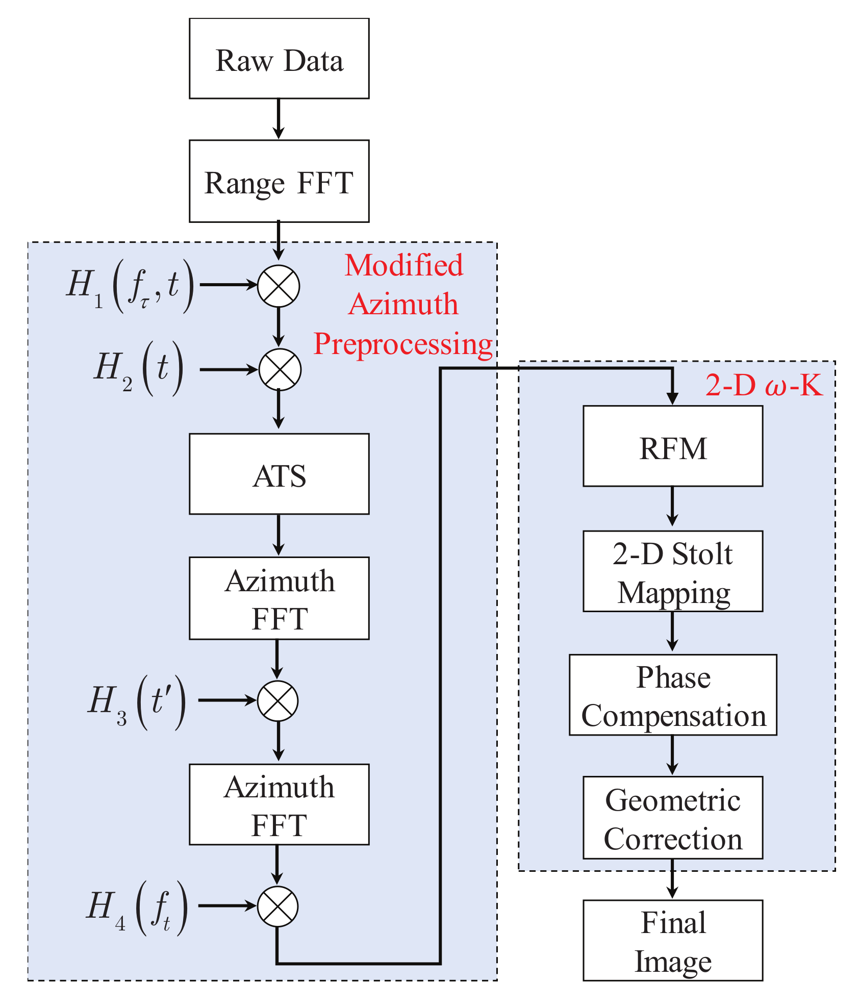
Based on the proposed BiCoT-ESRM, a 2-D frequency-domain imaging method is derived for GEO-LEO BiSAR in sliding-spotlight mode. Three problems need to be addressed for the accurate focusing of echo data. First, both the azimuth variance of Doppler centroid in GEO-LEO BiSAR and the steering of antenna beam in sliding-spotlight mode will result in the increase of the azimuth bandwidth, which causes azimuth aliasing. The two-step preprocessing scheme [56] is modified to remove the Doppler aliasing in azimuth frequency domain. Second, the equivalent circular orbit trajectory in (11) introduces azimuth variance of the motion parameters. In this paper, an azimuth trajectory scaling is proposed and integrated in the preprocessing scheme to resample the azimuth trajectory to a uniform linear motion. The third problem is the 2-D spatial variance of echo data brought by GEO-LEO BiSAR imaging configuration. This problem is solved by a modified 2-D ω k method in Section 3.2. Next, we will analyze the modified azimuth preprocessing and 2-D ω k method in detail.

3.1. Modified Azimuth Preprocessing

The echo data in (1) is transformed into range frequency domain by range FFT, and the phase term is given by
ϕ 1 f τ , t = π f τ 2 k r 2 π f 0 + f τ c R b i t
where f τ is the range frequency variable. Then, an azimuth phase multiplication is introduced to eliminate the spectrum skewing and align the azimuth spectrum to base band, which facilitates the subsequent processing.
H 1 f τ , t = exp j 2 π f d c f τ 2 R e v e sin ω e t 2
where v e = ω e R e r e f is the equivalent platform velocity with respect to the reference target. f d c ( f τ ) denotes the range frequency dependent Doppler centroid of the reference target. Based on (11), f d c ( f τ ) can be expressed as
f d c f τ = f 0 + f τ sin θ e r e f ω e r e f R e r e f c
where superscript ’ r e f ’ represents the corresponding parameters for the reference target. According to (10) and the derivations in the Appendix A, the Doppler centroid in (14) is contributed by the first-order coefficients of the range models of GEO transmitter, LEO receiver and ‘stop-and-go’ assumption error. In contrast to a monostatic LEO-SAR, the Doppler centroid in GEO-LEO BiSAR is dependent on the orbit position of the GEO transmitter [24], which should be removed.
During the data acquisition of a sliding-spotlight mode, the steering of the antenna beam leads to the azimuth variance of Doppler centroid. In addition, the translational variant imaging configuration of GEO-LEO BiSAR further aggravates the azimuth variance of Doppler centroid [24]. This variance will increase the total Doppler bandwidth and causes azimuth aliasing. Therefore, the two-step preprocessing method [56] is modified to remove the azimuth variance of Doppler centroid and eliminate the azimuth aliasing.
H 2 t = exp j π K r o t b i 2 R e v e sin ω e t 2 2
where K r o t b i is the bistatic deramping factor, which is calculated by
K r o t b i = v r 2 λ R r o t cos θ s + Δ k T 1 s v b λ
where v r is the effective velocity of the LEO receiver and R r o t is the slant range of the sliding-spotlight rotation center [46]. Δ k T 1 s is the partial derivative of k T 1 s with respect to azimuth position variable y, which is derived in Appendix A. v b is the beam footprint velocity of the LEO receiver with beam steering, which is given by
v b = ω b s R r o t R R 0
where ω b s is the constant beam rotation rate. In (16), the first term is caused by the beam steering of the LEO receiver and the second term is related to the azimuth variance of Doppler centroid introduced by the bistatic configuration. After the above bistatic deramping processing, the aliasing of Doppler spectrum is removed.
Inspecting (11), the BiCoT-ESRM is the sum of a constant range and a square-root term with an additional fourth-order compensation term. However, the equivalent radar movement is still a circular orbit trajectory, which contains higher-order components of azimuth time t. Direct solutions of 2-D spectrum using (11) is complicated and difficult. Moreover, the equivalent circular orbit trajectory will introduce azimuth variance of motion parameters, which should be eliminated. To this end, the following azimuth trajectory scaling (ATS) is formulated
v e t = 2 sin ω e t 2 R e .
After ATS, the azimuth phase can be expressed as
ϕ 2 f τ , t = π f τ 2 k r 2 π f 0 + f τ c R b i E q t + π K r o t b i t 2 2 π f d c f τ t
where R b i E q t is given by
R b i E q t = R T 0 s + R R 0 2 + v e 2 t 2 2 R R 0 v e t sin θ e + k T 4 s + Δ k e r r 4 arcsin v e t 2 R e · 2 w e 4 .
It can be observed from (20) that the equivalent radar movement is scaled to a uniform linear motion with velocity v e by ATS, where azimuth variance of motion parameters has been removed. Noted that ATS can be implemented by an azimuth interpolation procedure.
After azimuth trajectory scaling, zero padding, azimuth FFT and phase compensation can be subsequently employed according to the original two-step method [56]. The compensation factor in azimuth time domain is given by
H 3 t = exp j π K r o t b i t 2 .
The above preprocessing is essentially a convolution process. Therefore, the echo is transformed into 2-D frequency domain by an azimuth FFT and the following phase function is introduced to offset the convolution operation.
H 4 f t = exp j π f t 2 K r o t b i
where f t is the azimuth frequency variable.
After the above preprocessing, the effective pulse repetition frequency (PRF) is changed, and azimuth aliasing is removed in the azimuth frequency domain [56]. Moreover, the azimuth variance caused by circular orbit trajectory is also eliminated.

3.2. 2-D Frequency-Domain Focusing Method Based on BiCoT-ESRM

Based on the above analysis, the two-dimensional spectrum of the signal after preprocessing can be derived by principle of stationary phase based on (12) and (20)
ϕ 3 f τ , f t = f τ 2 k r 2 π f 0 + f τ c R T 0 s 2 π R R 0 cos θ e f 0 + f τ c 2 f t v e 2 2 π f t t 0 2 π f t R R 0 sin θ e v e + ϕ e r r 4 f τ , f t
where t 0 is the beam center crossing time of an arbitrary target P. ϕ e r r 4 is the fourth-order compensation term given by
ϕ e r r 4 f τ , f t = 2 π f 0 + f τ c k T 4 s + Δ k e r r 4 2 w e arcsin v e t p o s p 2 R e 4
where t p o s p is the position of stationary phase given by
t p o s p = R R 0 sin θ e + R R 0 cos θ e 1 v e 2 f 0 + f τ 2 c 2 f t 2 1 v e + t 0 .
During the derivation of (23), the fourth-order term is ignored for solving t p o s p . In (23), the first term is the range modulation phase, and the second term represents a range offset. The third term contains azimuth modulation, range cell migration (RCM) and secondary range compression (SRC). The fourth and fifth terms are linear phases of azimuth frequency, respectively, which are determined by the azimuth position of the targets.
Then, the reference function is multiplied with (23) to achieve the range compression, bulk azimuth demodulation, bulk RCM correction, bulk SRC and fourth-order phase compensation. The reference function is given by
H 5 f τ , f t = exp π f τ 2 k r + 2 π f 0 + f τ c R T 0 s r e f × exp 2 π f t R R 0 r e f sin θ e r e f v e + ϕ e r r 4 r e f × exp 2 π R R 0 r e f cos θ e r e f f 0 + f τ c 2 f t v e 2 .
After reference function multiplication (RFM), the phase of the reference target is completely compensated. However, residual phase errors exist for the targets away from the reference target, which is given by
ϕ 4 f τ , f t = 2 π f 0 + f τ c Δ R T 0 s 2 π f t Δ T 1 + t 0 2 π Δ R 1 f 0 + f τ 2 c 2 f t 2 v e 2
where
Δ R T 0 s = R T 0 s R T 0 s r e f Δ T 1 = R R 0 sin θ e v e R R 0 r e f sin θ e r e f v e Δ R 1 = R R 0 cos θ e R R 0 r e f cos θ e r e f
The spatial variance of ϕ e r r 4 is extremely small and can be arguably ignored. Then, according to the 2-D Stolt mapping [24], Δ R T 0 s and Δ T 1 are expanded to the first-order terms with respect to spatial variable y and R R 0 cos θ e , given by
Δ R T 0 s p 1 y + q 1 Δ R 1 Δ T 1 p 2 y + q 2 Δ R 1
where p 1 , q 1 , p 2 and q 2 are the first-order expanding coefficients of Δ R T 0 s and Δ T 1 . The detailed derivations and expressions of these coefficients are given in the Appendix A. Substituting (29) into (27) yields
ϕ 4 f τ , f t 2 π y p 1 f 0 + f τ c + f t p 2 + 1 v b 2 π Δ R 1 q 1 f 0 + f τ c + q 2 f t + f 0 + f τ 2 c 2 f t 2 v e 2 .
Let the frequency variable of y and Δ R 1 be equal to two new spatial frequency variables f y and f Δ R 1 , respectively. The 2-D Stolt mapping can then be expressed as
f y = p 1 f 0 + f τ c + f t p 2 + 1 v b f Δ R 1 = q 1 f 0 + f τ c + q 2 f t + f 0 + f τ 2 c 2 f t 2 v e 2 .
After the 2-D Stolt interpolation, the residual phase is given by
ϕ 5 f τ , f t = 2 π y f y 2 π Δ R 1 f Δ R 1 .
The residual phase is linear with the spatial axis y , Δ R 1 and the spatial frequency f y , f Δ R 1 . It should be noted that the higher-order terms during the expansion in (29) are ignored, which will introduce phase errors during the imaging. The error compensation procedure proposed in [24] can be used to eliminate the higher-order phase errors. In addition, the geometric correction presented in [24] can be implemented to eliminate the image distortion by a 1-D interpolation from the imaging plane ( Δ R 1 , y ) to ground plane ( x , y ) . Finally, a focused image can be generated.
The flowchart of the proposed imaging algorithm for GEO-LEO BiSAR in sliding-spotlight mode is given in Figure 5.

4. Experimental Results

In this section, numerical simulations of GEO-LEO bistatic SAR in sliding-spotlight mode are conducted to verify the effectiveness of the imaging method. Then, the real data-processing results of an equivalent bistatic SAR experiment are illustrated to further validate the proposed method using the China’s GF-3 LEO-SAR [57] as the transmitter and a stationary receiver.

4.1. Simulation Results of Sliding-Spotlight GEO-LEO BiSAR

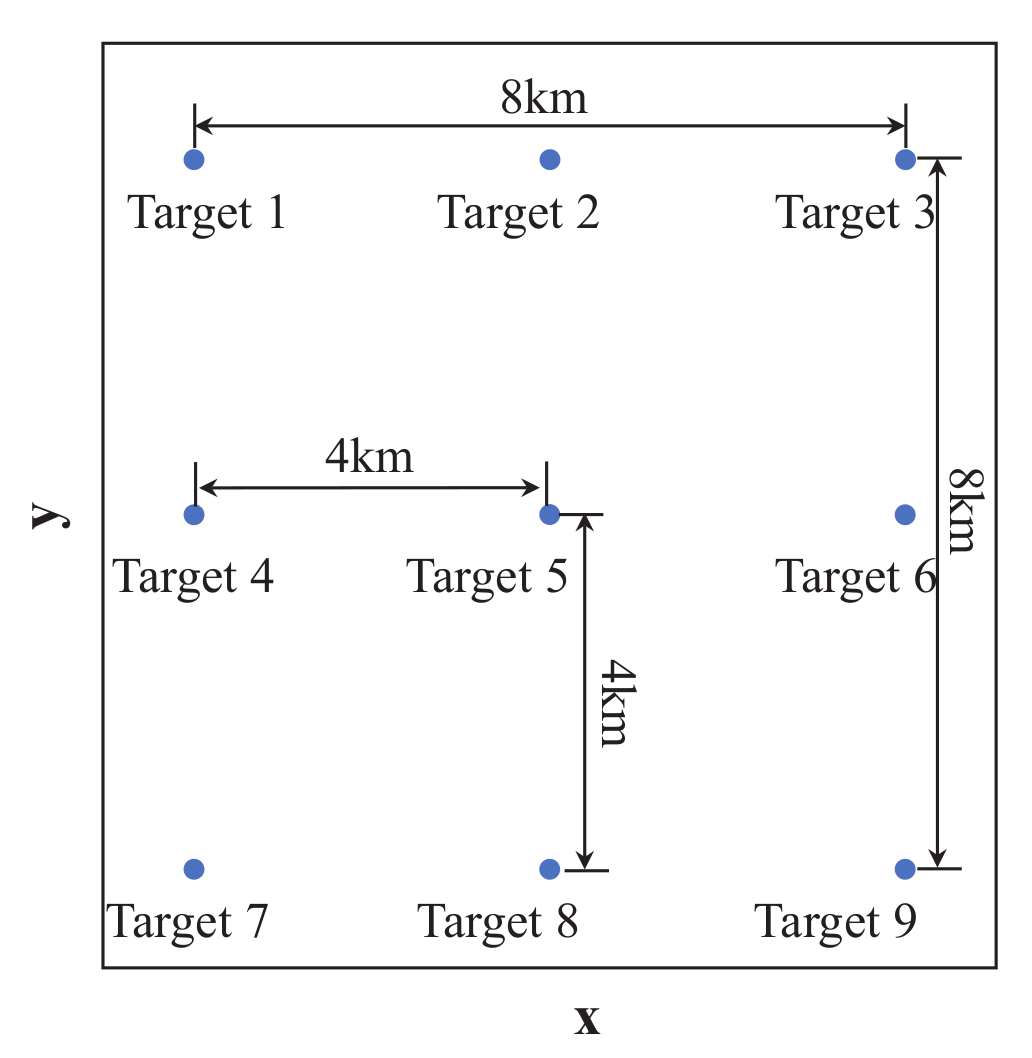
The simulation parameters have been listed in Table 1. The raw data of nine point targets of sliding-spotlight GEO-LEO BiSAR are generated. The positions of the nine simulated targets are shown in Figure 6. The point targets are evenly distributed in the 8 km × 8 km imaging scene with 4 km distance between adjacent targets both in x and y directions. The imaging performance of the proposed method is compared with the RMOSE method in [24]. In order to better illustrate the performance of the competing methods, the ‘stop-and-go’ assumption error is taken into consideration in the RMOSE method as simulated in Section 2.3. Moreover, the two-step preprocessing scheme [56] is implemented for RMOSE method to remove the azimuth aliasing in sliding-spotlight mode.
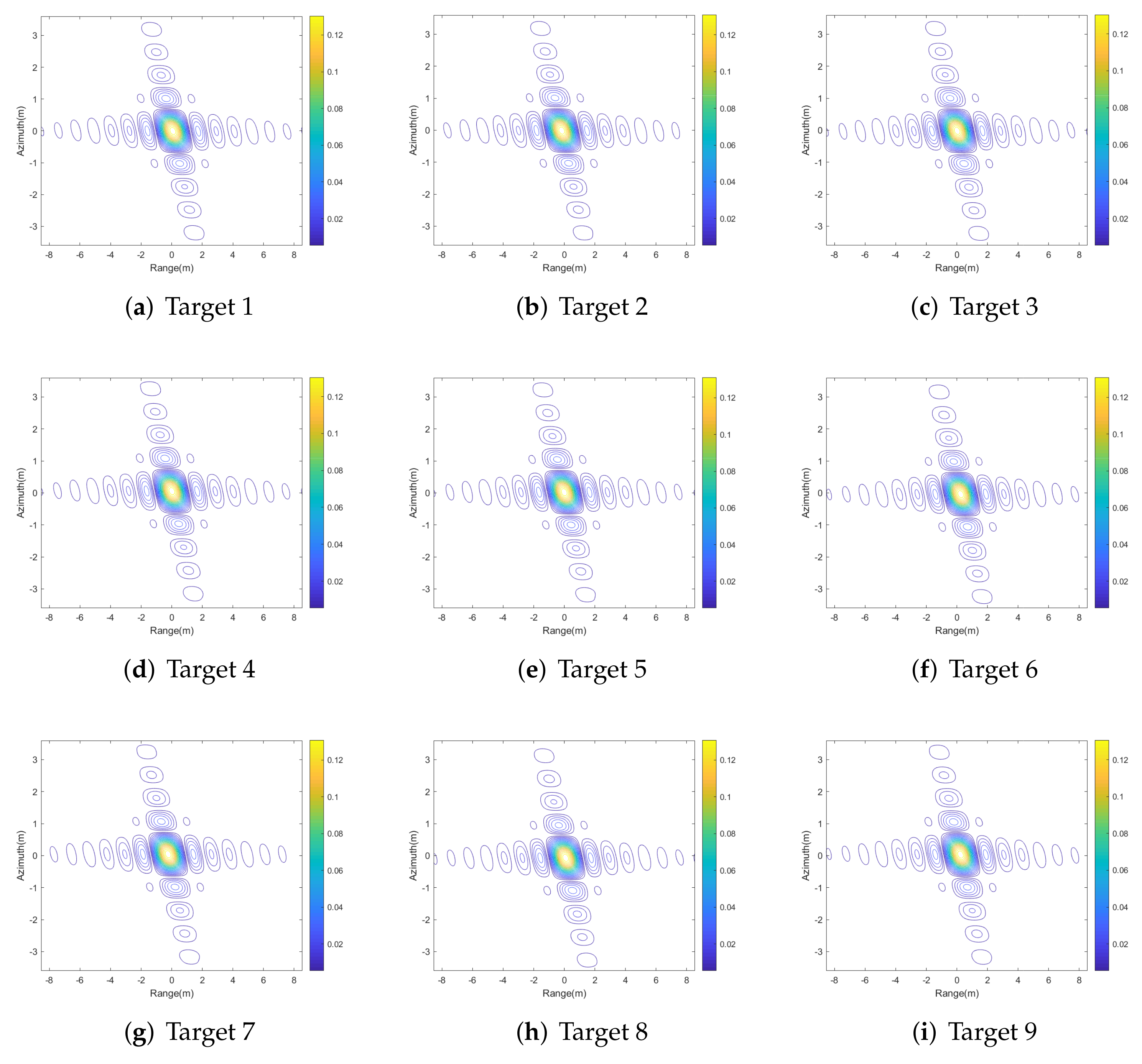
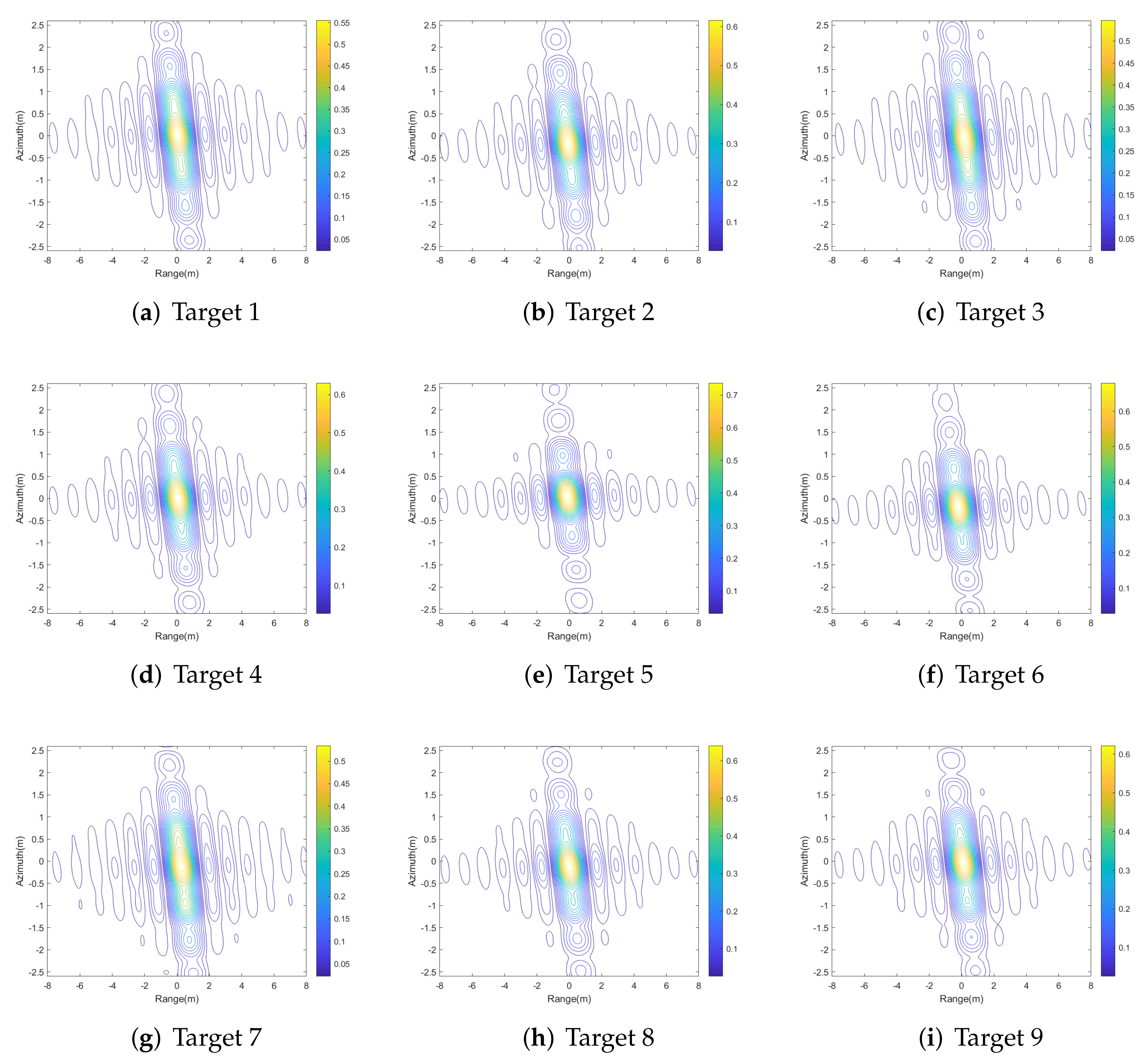
The imaging results of the nine point targets processed by the proposed method and RMOSE are illustrated in Figure 7 and Figure 8, respectively. It can be observed that all nine targets are defocused by RMOSE in Figure 8, especially in azimuth direction. The main reason for the performance degradation of RMOSE is the range model error shown in Figure 3. The range error increases with longer synthetic aperture time and introduces significant phase error during the imaging procedure in sliding-spotlight GEO-LEO BiSAR. For the targets away from the reference point, the imaging results are further deteriorated due to the errors in 2-D Stolt mapping. On the other hand, the proposed method achieves satisfactory imaging performance for all nine targets as shown in Figure 7.
The measured metrics of the imaging results of the proposed method and RMOSE are given in Table 2 and Table 3, respectively. The theoretical values of peak sidelobe ratio (PSLR) and integrated sidelobe ratio (ISLR) are −13.26 dB and −10.4 dB, respectively. The 3 dB impulse response width (IRW) is 0.68 m in the azimuth direction and 1.01 m in the range direction, which are calculated based on the system parameters and bistatic configuration. It can be seen that the imaging performance metrics of the proposed method are close to the theoretical values. However, for RMOSE, the PSLR and ISLR in azimuth direction are greatly degraded with widening of azimuth IRW.
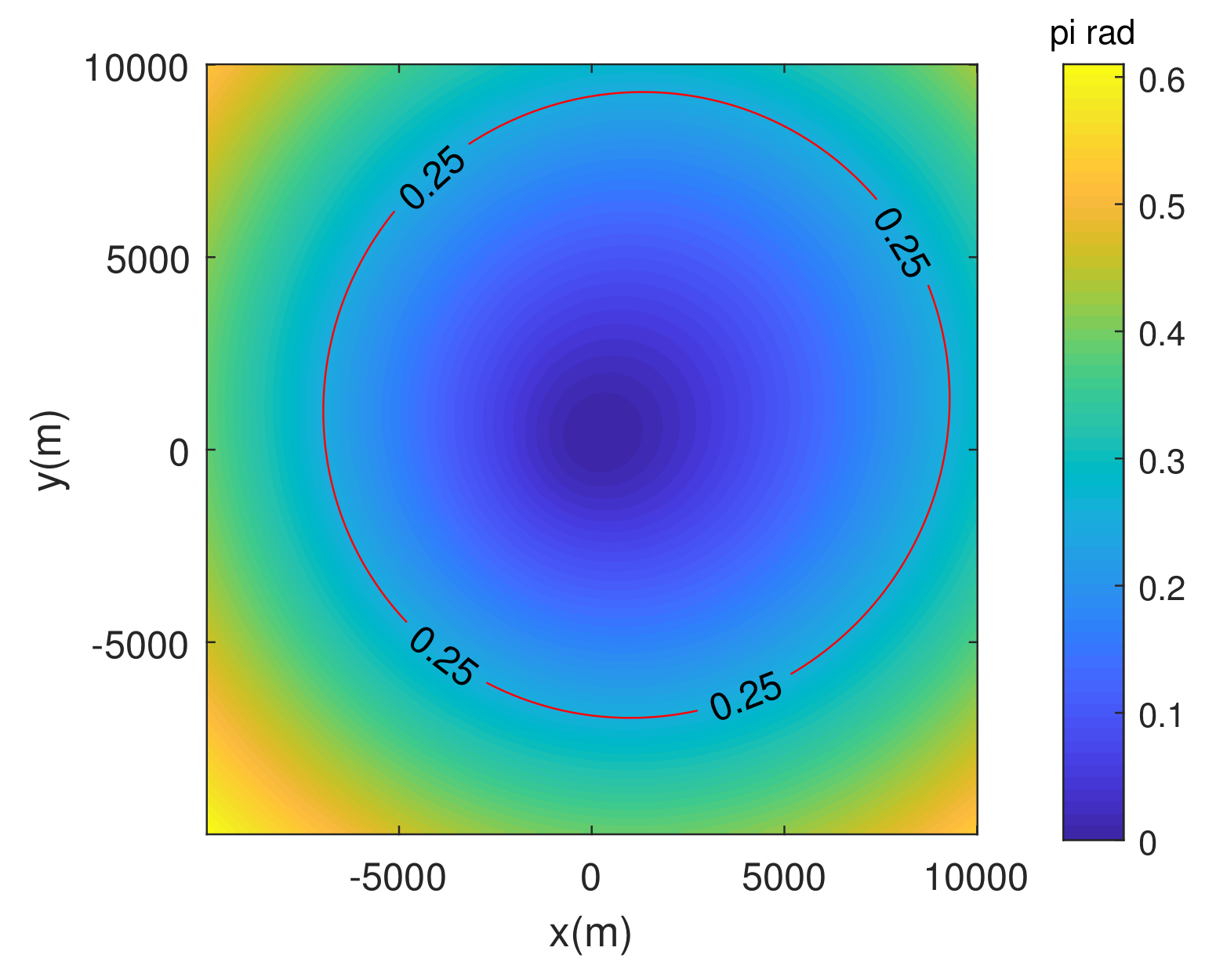
As analyzed above, the two-dimensional linear spatial variation of the echo data is removed using two-dimensional Stolt interpolation. The space-invariant higher-order residual phase error is compensated for by using the higher-order phase error of the scene center. Therefore, the main error source that limits the imaging swath width of the algorithm is the residual spatial variant higher-order phase error. When the spatial variant higher-order phase term reaches π / 4 , it will affect the focusing effect and introduce focusing degradation. Therefore, the imaging swath of the method in both range and azimuth will be limited. In addition, the focusing effect becomes worse as the target is further away from the scene center. The residual higher-order phase error of the simulated GEO-LEO sliding-spotlight SAR in Section 4.1 is given in Figure 9, where the simulation parameters and system configuration are given in Table 1. From Figure 9, it can be seen that when the image width is within 10 km × 10 km, the residual higher-order phase is less than π / 4 , and the image quality is not affected.

4.2. Equivalent Experiment with GF-3 Transmitter and Stationary Receiver

To further test the performance of the proposed method, a preliminary equivalent bistatic SAR experiment is conducted, which mainly aims at simulating the echo characteristics of sliding-spotlight GEO-LEO BiSAR. It should be noted that other aspects of GEO-LEO BiSAR, including ionospheric interference and illuminating power, etc., are not considered in the equivalent experiment. In the equivalent experiment, China’s C-band GF-3 LEO-SAR satellite was utilized as the transmitter, which works in sliding-spotlight mode. A stationary receiver was mounted on the top of a mountain, with an additional pair of antennae and corresponding channels for direct signal synchronization. The system and platform parameters of the bistatic SAR experiment are given in Table 4. The experiment was conducted in October 2020 in Zhoushan City, China. The total data take duration is 6 s in sliding-spotlight mode, corresponding to theoretical 2-D resolution of 0.91 m in azimuth direction and 0.76 m in range direction, respectively.
The equivalence of the experiment with GEO-LEO BiSAR regarding echo characteristics is analyzed in three aspects, where the same system parameters are assumed. First, due to the lack of operating GEO-SAR system, a stationary platform is used to approximate the motion characteristics of a GEO-SAR transmitter. The angular speed of a GEO-SAR is generally quite small due to the high-orbit altitude [6]. The relative motion between GEO-SAR and the target scene is slight during several seconds of synthetic aperture time. Therefore, the stationary platform can approximate the motion of GEO-SAR without significant error in cases with low inclination or geostationary orbit. It should be noted that the exchange of transmitting and receiving platforms does not affect the echo characteristics.
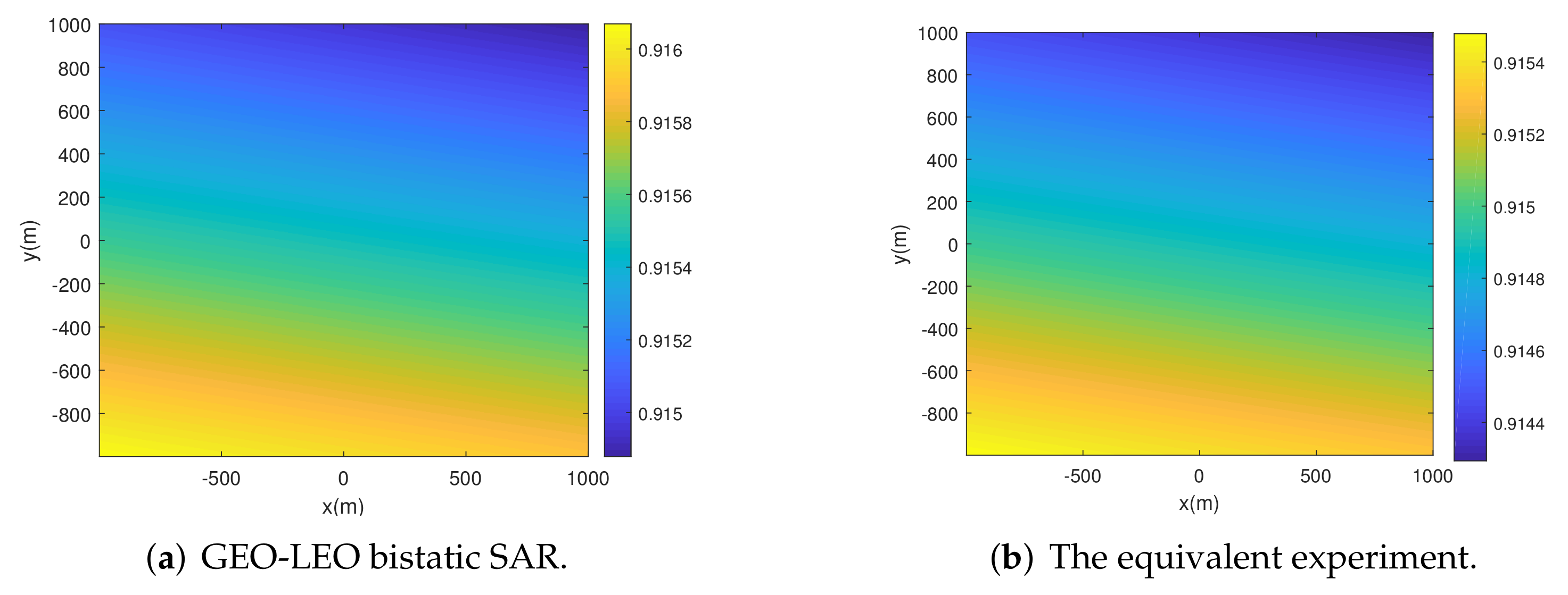
The azimuth resolution and its spatial variance of GEO-LEO BiSAR and the equivalent experiment are illustrated in Figure 10. The spatial variance is shown in a scene size of 2 km × 2 km. It can be observed that similar azimuth resolution performance can be achieved by the equivalent BiSAR experiment compared to GEO-LEO BiSAR. The spatial variance of azimuth resolutions are linear in both x and y directions with approximately the same magnitude. The azimuth resolution is dependent on the rotation angles of the transmitting and receiving platforms with respect to the target scene during the synthetic aperture [6]. For a GEO-LEO bistatic SAR system, the contribution of GEO transmitter is negligible compared with that of LEO receiver within a few seconds of synthetic aperture. Therefore, the equivalent experiment can provide satisfactory approximation regarding azimuth resolution.
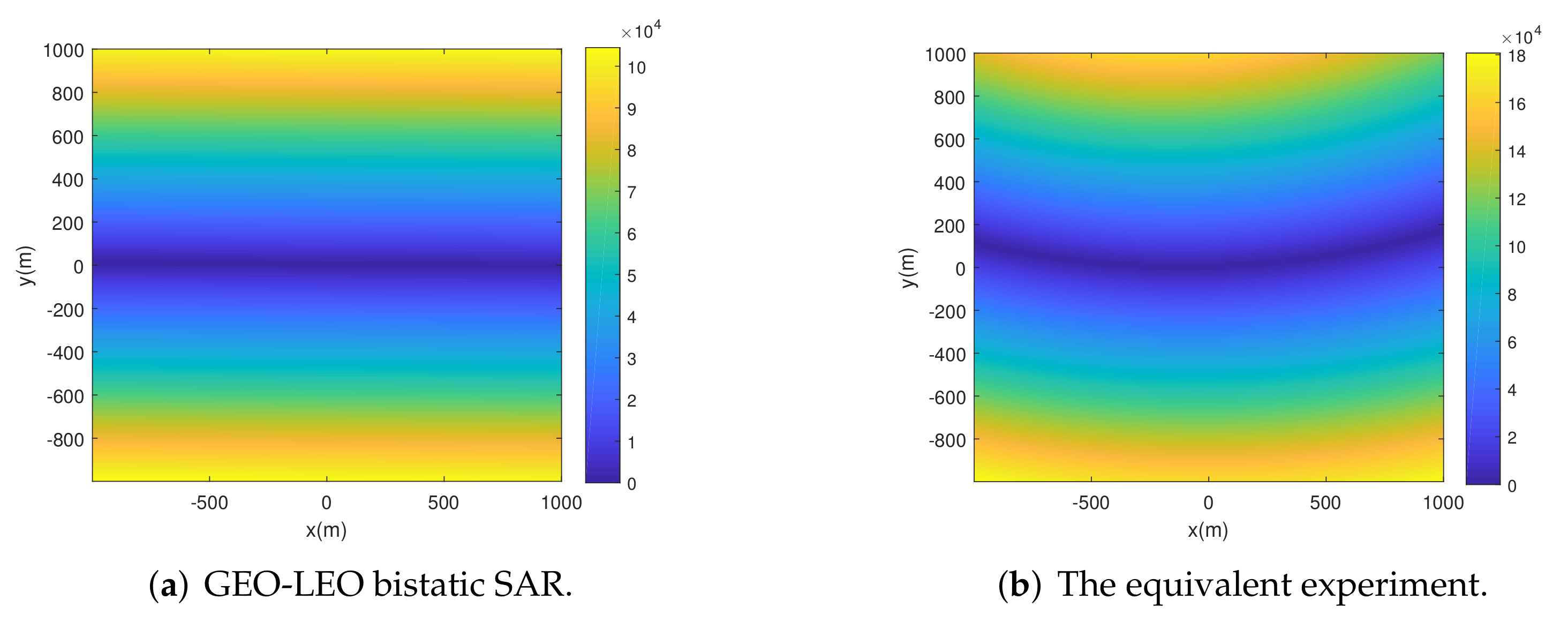
Finally, the azimuth phase and its spatial variance of GEO-LEO BiSAR and the equivalent experiment are illustrated in Figure 11, which are determined by the range model characteristics. It can be observed that the spatial variance of the azimuth phase of the equivalent experiment has a similar pattern to that of GEO-LEO BiSAR. However, the spatial variance of the equivalent experiment is more significant. This is because the stationary receiver is closer to the imaging scene and will have a greater influence on the spatial variance than GEO-SAR. The performance of the proposed imaging method can be tested in a more difficult scenario.
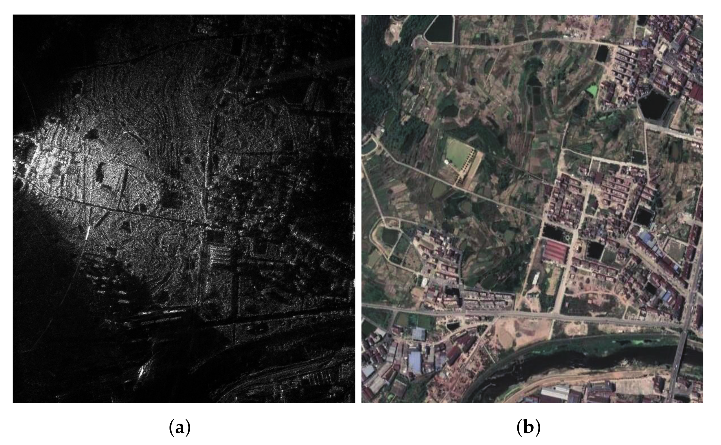
The real data-processing result is shown in Figure 12a, with 1.1 km × 1 km scene size. The corresponding optical image is captured from Google Earth for comparison in Figure 12b. In contrast, the imaging result of the ‘non-stop-and-go’ is illustrated in Figure 12b. In contrast, the imaging result of the ‘non-stop-and-go’ RMOSE method is illustrated in Figure 13. An isolated strong target in the imaging result is further investigated to roughly evaluate the imaging performance. The azimuth and range profiles of the selected target by the proposed method are shown in Figure 14a and in Figure 14b, respectively. The measured azimuth resolution is 0.99 m, and the measured range resolution is 0.81 m, which are close to the theoretical values. The corresponding profiles of the selected target in the imaging result of the ‘non-stop-and-go’ RMOSE method are given in Figure 14c and Figure 14d, respectively. The quantitative results in terms of peak sidelobe ratio (PSLR), integrated sidelobe ratio (ISLR), and impulse response width (IRW) are listed in Table 5. It can be observed that the azimuth IRW of the selected isolated target is significantly coarsened, which causes defocusing in the imaging result. Please note that the selected target is a non-cooperative target. Therefore, the above measured metric is only a rough estimate of the spatial resolution.

5. Conclusions

In this paper, a novel accurate range model, i.e., BiCoT-ESRM, is proposed for GEO-LEO BiSAR. The BiCoT-ESRM takes into consideration the curved trajectory of LEO receiver and ‘stop-and-go’ assumption error in GEO-LEO BiSAR. It can provide high-precision approximation for the range history of GEO-LEO BiSAR within long synthetic aperture. Then, based on BiCoT-ESRM, a 2-D frequency imaging method is put forward. First, the two-step method is modified to deal with the Doppler aliasing caused by beam steering and spatial variance of Doppler centroid. Then, an azimuth trajectory scaling is introduced to resample the platform movement to a uniform linear motion and remove the azimuth variance of motion parameters. Finally, a modified 2-D ω k method is derived for the accurate focusing of sliding-spotlight GEO-LEO BiSAR. The proposed method is tested both in simulated GEO-LEO BiSAR data and real data from an equivalent BiSAR experiment. Imaging results validate the effectiveness of the proposed range model and imaging algorithm. Based on the aforementioned analysis, the BoCoT-ESRM can precisely represent the range history of GEO-LEO BiSAR, which can be applied to most of the imaging modes and configurations. However, the proposed imaging method is designed for sliding-spotlight GEO-LEO BiSAR, which generally cannot be applied to other modes and bistatic configurations, such as stripmap or scan SAR. The development of imaging methods for other modes will be our future work.

Author Contributions

Z.S. put forward the main idea, designed the experiment and wrote the manuscript. J.W., T.C., H.S., Z.L. (Zheng Lu), Z.L. (Zhiyong Liu), H.A. and J.Y. participated in the experiment. H.S. participated in the revision of the manuscript. All authors have read and agreed to the published version of the manuscript.

Funding

This work was supported in part by the National Natural Science Foundation of China under Grant 61901088, Grant 61922023, Grant 61771113, and Grant 61801099, in part by the Postdoctoral Innovation Talent Support Program under Grant BX20180059, and in part by the China Postdoctoral Science Foundation under Grant 2020M683292, 2019M65338 and Grant 2019TQ0052.

Data Availability Statement

Not applicable.

Conflicts of Interest

The authors declare no conflict of interest.

Appendix A

Appendix A.1. Expanding Coefficients of R R t s + τ d

The expanding coefficients of R R t s + τ d are given as follows.
a 1 = k R 1 + 2 k R 2 t s + 3 k R 3 t s 2 + 4 k R 4 t s 3
a 2 = k R 2 + 3 k R 3 t s + 6 k R 4 t s 2
a 3 = k R 3 + 4 k R 4 t s

Appendix A.2. Derivation of Equivalent Parameters of BiCoT-ESRM

The equivalent parameters can be obtained by letting the first-, second-, and third-order expanding coefficients of (11) equal to those of (10). An equation system regarding ω e , R e and θ e can be constructed as follows
k b 1 = sin θ e · ω e R e k b 2 = cos 2 θ e · ω e 2 R e 2 / 2 R R 0 k b 3 = cos 2 θ e sin θ e · ω e 3 R e 3 / 2 R R 0 2 + ω e 3 R e sin θ e / 24
where k b 1 , k b 2 and k b 3 are the expanding coefficients of (10) given by
k b 1 = sin θ s · ω s R s + k T 1 s k b 2 = cos 2 θ s 2 R R 0 · ω s 2 R s 2 + k T 2 s k b 3 = cos 2 θ s sin θ s 2 R R 0 2 · ω s 3 R s 3 + ω s 3 R s sin θ s 24 + k T 3 s
Solving (A4) yields
θ e = arcsin k b 1 k b 1 2 + 2 R R 0 k b 2 ω e = 24 k b 3 k b 1 + k b 2 R R 0 R e = k b 1 2 + 2 R R 0 k b 2 ω e

Appendix A.3. Derivation of the Expanding Coefficients of Δ R T 0 s and Δ T 1 with Respect to y and Δ R 1

The first-order expanding coefficients of Δ R T 0 s and Δ T 1 in (28) with respect to y and Δ R 1 are related to the positions of transmitting and receiving platforms at the beam center crossing time, which are denoted as x T , y T , z T and x R , y R , z R , respectively. Therefore, R T 0 , R R 0 , and sin θ s can be expressed as
R T 0 = x T x 2 + y T y 2 + z T 2
R R 0 = x R x 2 + y R y 2 + z R 2
sin θ s = y y R x x R 2 + y y R 2 + z R 2

Appendix A.4. Derivations of p1 and q1

p 1 and q 1 are the Taylor expansion coefficients of Δ R T 0 s with respect to y and Δ R 1 , respectively. First, p 1 can be expressed as
p 1 = Δ R T 0 s y y = 0 = R T 0 s R T 0 s r e f y y = 0 = c τ d 0 y R R 0 y y = 0
where
τ d 0 y = k R 2 k R 1 y Θ y k R 2 y c k R 1 Θ 2 k R 2 2
where k R 1 / y , k R 2 / y and Θ / y can be expressed as
k R 1 y = ω s R s sin θ s y k R 2 y = cos 2 θ s 2 R R 0 · ω s 2 R s 2 y
= ω s 2 R s 2 2 cos θ s cos θ s y R R 0 cos 2 θ s R R 0 y 2 R R 0 2 Θ y = k R 1 c 2 4 k R 2 R T 0 + R R 0 y
= k R 1 c k R 1 y 2 k R 2 y R T 0 + R R 0 2 k R 2 R T 0 y + R R 0 y k R 1 c 2 4 k R 2 R T 0 + R R 0
where R T 0 / y , R R 0 / y and cos θ s / y are given by
R T 0 y = y y T x x T 2 + y y T 2 + z T 2
R R 0 y = y y R x x R 2 + y y R 2 + z R 2
sin θ s y = x x R 2 + z R 2 x R x 2 + y R y 2 + z R 2 3 2
cos θ s y = sin θ s 1 sin 2 θ s sin θ s y
Then, q 1 can be derived as
q 1 = Δ R T 0 s Δ R 1 = R T 0 s R T 0 s r e f Δ R 1 x = 0 = R T 0 s x Δ R 1 x 1 x = 0
where R T 0 s / x can be derived in a similar manner to R T 0 s / y in (A10), and Δ R 1 / x can be expressed as
Δ R 1 x = R R 0 cos θ e R R 0 r e f cos θ e r e f x = R R 0 x cos θ e + R R 0 cos θ e x
where
R R 0 x = x x R x x R 2 + y y R 2 + z R 2
cos θ e x = sin θ e 1 sin 2 θ e · sin θ e x
in which
sin θ e x = k b 1 k b 1 2 + 2 R R 0 k b 2 x · k b 1 k b 2 R R 0 x + k b 1 R R 0 k b 2 x 2 k b 2 R R 0 k b 1 x k b 1 2 + 2 R R 0 k b 2 3 2
where
k b 1 x = k T 1 s + k R 1 x = k T 1 x + k R 1 x + Δ k 1 x
k b 2 x = k T 2 s + k R 2 x = k T 2 x + k R 2 x + Δ k 2 x
In (A24) and (A25), k T 1 / x and k T 2 / x can be obtained according to the derivations in Appendix 6 in [24]. k R 1 / x and k R 2 / x can be derived in a similar manner to k R 1 / y and k R 2 / y as in (A12) and (), respectively. The expressions of Δ k 1 / x and Δ k 2 / x are rather complicated, which can be derived by professional software and are not listed here for simplicity.

Appendix A.5. Derivation of p2 and q2

Derivation of p 2 and q 2 can be calculated in a similar way as p 1 and q 1 .
p 2 = Δ T 1 y y = 0
= R R 0 y sin θ e + R R 0 sin θ e y v e y = 0 q 2 = Δ T 1 Δ R 1 x = 0
= Δ T 1 x R R 0 cos θ e R R 0 r e f cos θ e r e f x 1 x = 0
It can be observed from (A26) and (A27) p 2 and q 2 are composed of R R 0 , sin θ e , cos θ e and corresponding derivatives, which can be derived in a similar way to p 1 and q 1 .

References

  1. Huang, P.; Xia, X.G.; Wang, L.; Xu, H.; Liu, X.; Liao, G.; Jiang, X. Imaging and Relocation for Extended Ground Moving Targets in Multichannel SAR-GMTI Systems. IEEE Trans. Geosci. Remote Sens. 2021, 60, 1–24. [Google Scholar] [CrossRef]
  2. Huang, P.; Xia, X.G.; Zhan, M.; Liu, X.; Liao, G.; Jiang, X. ISAR Imaging of a Maneuvering Target Based on Parameter Estimation of Multicomponent Cubic Phase Signals. IEEE Trans. Geosci. Remote Sens. 2022, 60, 1–18. [Google Scholar] [CrossRef]
  3. Huang, P.; Zou, Z.; Xia, X.G.; Liu, X.; Liao, G.; Xin, Z. Multichannel Sea Clutter Modeling for Spaceborne Early Warning Radar and Clutter Suppression Performance Analysis. IEEE Trans. Geosci. Remote Sens. 2021, 59, 8349–8366. [Google Scholar] [CrossRef]
  4. Li, Z.; Ye, H.; Liu, Z.; Sun, Z.; An, H.; Wu, J.; Yang, J. Bistatic SAR Clutter-Ridge Matched STAP Method for Non-stationary Clutter Suppression. IEEE Trans. Geosci. Remote Sens. 2021, 60, 1. [Google Scholar] [CrossRef]
  5. Tomiyasu, K.; Pacelli, J.L. Synthetic Aperture Radar Imaging from an Inclined Geosynchronous Orbit. IEEE Trans. Geosci. Remote Sens. 1983, GE-21, 324–329. [Google Scholar] [CrossRef]
  6. Sun, Z.; Wu, J.; Pei, J.; Li, Z.; Huang, Y.; Yang, J. Inclined Geosynchronous Spaceborne-Airborne Bistatic SAR: Performance Analysis and Mission Design. IEEE Trans. Geosci. Remote Sens. 2016, 54, 343–357. [Google Scholar] [CrossRef]
  7. Ruiz-Rodon, J.; Broquetas, A.; Makhoul, E.; Monti Guarnieri, A.; Rocca, F. Nearly Zero Inclination Geosynchronous SAR Mission Analysis With Long Integration Time for Earth Observation. IEEE Trans. Geosci. Remote Sens. 2014, 52, 6379–6391. [Google Scholar] [CrossRef]
  8. Long, T.; Zhang, T.; Ding, Z.; Yin, W. Effect Analysis of Antenna Vibration on GEO SAR Image. IEEE Trans. Aerosp.Electron. Syst. 2019, 56, 1. [Google Scholar] [CrossRef]
  9. Li, Y.; Hu, C.; Dong, X.; Zhang, B.; Li, S.; Ao, D. Influence of Orbit and System Parameters on Geosynchronous SAR Multiple-Aperture Interferometry Processing: Analysis and Validation. IEEE J. Sel. Top. Appl. Earth Observ. Remote Sens. 2019, 12, 1798–1811. [Google Scholar] [CrossRef]
  10. Chen, J.; Sun, G.; Xing, M.; Yang, J.; Ni, C.; Zhu, Y.; Shu, W.; Liu, W. A Parameter Optimization Model for Geosynchronous SAR Sensor in Aspects of Signal Bandwidth and Integration Time. IEEE Geosci. Remote Sens. Letts. 2016, 13, 1374–1378. [Google Scholar] [CrossRef]
  11. Hobbs, S.; Mitchell, C.; Forte, B.; Holley, R.; Snapir, B.; Whittaker, P. System Design for Geosynchronous Synthetic Aperture Radar Missions. IEEE Trans. Geosci. Remote Sens. 2014, 52, 7750–7763. [Google Scholar] [CrossRef] [Green Version]
  12. Ding, Z.; Yin, W.; Zeng, T.; Long, T. Radar Parameter Design for Geosynchronous SAR in Squint Mode and Elliptical Orbit. IEEE J. Sel. Top. Appl. Earth Observ. Remote Sens. 2016, 9, 2720–2732. [Google Scholar] [CrossRef]
  13. Hu, C.; Long, T.; Liu, Z.; Zeng, T.; Tian, Y. An Improved Frequency Domain Focusing Method in Geosynchronous SAR. IEEE Trans. Geosci. Remote Sens. 2014, 52, 5514–5528. [Google Scholar] [CrossRef]
  14. Sun, G.; Xing, M.; Wang, Y.; Yang, J.; Bao, Z. A 2-D Space-Variant Chirp Scaling Algorithm Based on the RCM Equalization and Subband Synthesis to Process Geosynchronous SAR Data. IEEE Trans. Geosci. Remote Sens. 2014, 52, 4868–4880. [Google Scholar] [CrossRef]
  15. Zhang, T.; Ding, Z.; Tian, W.; Zeng, T.; Yin, W. A 2-D Nonlinear Chirp Scaling Algorithm for High Squint GEO SAR Imaging Based on Optimal Azimuth Polynomial Compensation. IEEE J. Sel. Top. Appl. Earth Observ. Remote Sens. 2017, 10, 5724–5735. [Google Scholar] [CrossRef]
  16. Hu, B.; Jiang, Y.; Zhang, S.; Zhang, Y.; Yeo, T. Generalized Omega-K Algorithm for Geosynchronous SAR Image Formation. IEEE Geosci. Remote Sens. Letts. 2015, 12, 2286–2290. [Google Scholar] [CrossRef]
  17. Hu, C.; Li, Y.; Dong, X.; Wang, R.; Ao, D. Performance Analysis of L-Band Geosynchronous SAR Imaging in the Presence of Ionospheric Scintillation. IEEE Trans. Geosci. Remote Sens. 2017, 55, 159–172. [Google Scholar] [CrossRef]
  18. Ji, Y.; Zhang, Y.; Dong, Z.; Zhang, Q.; Li, D.; Yao, B. Impacts of Ionospheric Irregularities on L-Band Geosynchronous Synthetic Aperture Radar. IEEE Trans. Geosci. Remote Sens. 2020, 58, 1–14. [Google Scholar] [CrossRef]
  19. Ruiz Rodon, J.; Broquetas, A.; Monti Guarnieri, A.; Rocca, F. Geosynchronous SAR Focusing With Atmospheric Phase Screen Retrieval and Compensation. IEEE Trans. Geosci. Remote Sens. 2013, 51, 4397–4404. [Google Scholar] [CrossRef]
  20. Sun, Z.; Yen, G.G.; Wu, J.; Ren, H.; An, H.; Yang, J. Mission Planning for Energy-Efficient Passive UAV Radar Imaging System Based on Substage Division Collaborative Search. IEEE Trans. Cybern. 2021, 1–14. [Google Scholar] [CrossRef]
  21. An, H.; Wu, J.; Teh, K.C.; Sun, Z.; Yang, J. Geosynchronous Spaceborne-Airborne Bistatic SAR Imaging Based on Fast Low-Rank and Sparse Matrices Recovery. IEEE Trans. Geosci. Remote Sens. 2021, 60, 1–14. [Google Scholar] [CrossRef]
  22. Wu, J.; Sun, Z.; An, H.; Qu, J.; Yang, J. Azimuth Signal Multichannel Reconstruction and Channel Configuration Design for Geosynchronous Spaceborne CAirborne Bistatic SAR. IEEE Trans. Geosci. Remote Sens. 2019, 57, 1861–1872. [Google Scholar] [CrossRef]
  23. An, H.; Wu, J.; Sun, Z.; Yang, J. A Two-Step Nonlinear Chirp Scaling Method for Multichannel GEO Spaceborne-Airborne Bistatic SAR Spectrum Reconstructing and Focusing. IEEE Trans. Geosci. Remote Sens. 2019, 57, 3713–3728. [Google Scholar] [CrossRef]
  24. Sun, Z.; Wu, J.; Li, Z.; An, H.; He, X. Geosynchronous Spaceborne-Airborne Bistatic SAR Data Focusing Using a Novel Range Model Based on One-Stationary Equivalence. IEEE Trans. Geosci. Remote Sens. 2021, 59, 1214–1230. [Google Scholar] [CrossRef]
  25. Zhang, Y.; Xiong, W.; Dong, X.; Hu, C. A Novel Azimuth Spectrum Reconstruction and Imaging Method for Moving Targets in Geosynchronous Spaceborne CAirborne Bistatic Multichannel SAR. IEEE Trans. Geosci. Remote Sens. 2020, 58, 5976–5991. [Google Scholar] [CrossRef]
  26. Dong, X.; Xiong, W.; Zhang, Y.; Hu, C.; Liu, F. A Novel Geosynchronous Spaceborne-Airborne Bistatic Multichannel Sar For Ground Moving Targets Indication. In Proceedings of the IEEE IGARSS, Yokohama, Japan, 28 July–2 August 2019; pp. 3499–3502. [Google Scholar] [CrossRef]
  27. Guttrich, G.; Sievers, W.; Tomljanovich, N. Wide area surveillance concepts based on geosynchronous illumination and bistatic unmanned airborne vehicles or satellite reception. In Proceedings of the IEEE National Radar Conference, Syracuse, NY, USA 13–15 May 1997; pp. 126–131. [Google Scholar] [CrossRef]
  28. Sarabandi, K.; Kellndorfer, J.; Pierce, L. GLORIA: Geostationary/Low-Earth Orbiting Radar Image Acquisition System: A multi-static GEO/LEO synthetic aperture radar satellite constellation for Earth observation. In Proceedings of the IEEE IGARSS, Toulouse, France, 21–25 July 2003; Volume 2, pp. 773–775. [Google Scholar] [CrossRef]
  29. Lu, Z.; Wang, Y.; Xu, M.; Zhu, Y.; Jian, L.; Li, Z. Spacecraft Formation Design for Bistatic SAR with GEO Illuminator and LEO Receiver. In Proceedings of the IEEE IGARSS, Valencia, Spain, 22–27 July 2018; pp. 4451–4454. [Google Scholar] [CrossRef]
  30. Wang, Y.; Lu, Z.; Suo, Z.; Zhu, Y.; Li, Z.; Zhang, Q. Optimal configuration of spaceborne bistatic SAR with GEO transmitter and LEO receiver. IET Radar, Sonar Navigat. 2019, 13, 229–235. [Google Scholar] [CrossRef]
  31. Krieger, G.; Moreira, A. Multistatic SAR satellite formations: Potentials and challenges. In Proceedings of the IEEE International Geoscience Remote Sensing Symposium (IGARSS), Seoul, Korea, 25–29 July 2005; Volume 4, pp. 2680–2684. [Google Scholar] [CrossRef] [Green Version]
  32. Xiao, P.; Liu, B.; Guo, W. ConGaLSAR: A Constellation of Geostationary and Low Earth Orbit Synthetic Aperture Radar. IEEE Geosci. Remote Sens. Letts. 2020, 17, 2085–2089. [Google Scholar] [CrossRef]
  33. Leanza, A.; Manzoni, M.; Monti-Guarnieri, A.; di Clemente, M. LEO to GEO-SAR Interferences: Modelling and Performance Evaluation. Remote Sens. 2019, 11, 1720. [Google Scholar] [CrossRef] [Green Version]
  34. Xiao, P.; Guo, W.; Wu, Y.; Liu, B. A Comprehensive Method of Ambiguity Suppression for Constellation of Geostationary and Low Earth Orbit SAR. IEEE J. Sel. Top. Appl. Earth Observ. Remote Sens. 2020, 13, 3327–3335. [Google Scholar] [CrossRef]
  35. Zhang, S.; Li, S.; Liu, Y.; Xing, M.; Chen, J. A Novel Azimuth Doppler Signal Reconstruction Approach for the GEO-LEO Bi-Static Multi-Channel HRWS SAR System. IEEE Access 2019, 7, 39539–39546. [Google Scholar] [CrossRef]
  36. Zhang, S.; Gao, Y.; Xing, M.; Guo, R.; Chen, J.; Liu, Y. Ground Moving Target Indication for the Geosynchronous-Low Earth Orbit Bistatic Multichannel SAR System. IEEE J. Sel. Top. Appl. Earth Observ. Remote Sens. 2021, 14, 5072–5090. [Google Scholar] [CrossRef]
  37. Yang, J.; Yi, Q.; Li, Z.; Wu, J.; Huang, Y. Efficient translational variant bistatic SAR raw data generation based on 2D inverse Stolt mapping. In Proceedings of the 2013 IEEE International Geoscience and Remote Sensing Symposium - IGARSS, Melbourne, VIC, Australia, 21–26 July 2013; pp. 2489–2492. [Google Scholar] [CrossRef]
  38. Xiao, P.; Guo, W.; Liu, M.; Liu, B. A Three-Step Imaging Algorithm for the Constellation of Geostationary and Low Earth Orbit SAR (ConGaLSAR). IEEE Trans. Geosci. Remote Sens. 2021, 60, 1–14. [Google Scholar] [CrossRef]
  39. Zhu, Y.; Lv, Z.; Wang, W.Q.; Liao, Y.; Zhang, S.; Zheng, Z. Nufft-Based Algorithm for Bistatic SAR Imaging Via Cooperative High-Orbit and Low-Orbit Satellites. In Proceedings of the 2019 IEEE IGARSS, Yokohama, Japan, 28 July–2 August 2019; pp. 3503–3506. [Google Scholar] [CrossRef]
  40. Zhang, X.; Gu, H.; Su, W. Focusing Bistatic Forward-looking SAR Images use Omega-k algorithm based on Modified Hyperbolic Approximating. In Proceedings of the 2019 International Conference on Control, Automation and Information Sciences (ICCAIS), Chengdu, China, 23–26 October 2019; pp. 1–5. [Google Scholar] [CrossRef]
  41. Wang, Y.; Liu, Y.; Li, Z.; Suo, Z.; Fang, C.; Chen, J. High-Resolution Wide-Swath Imaging of Spaceborne Multichannel Bistatic SAR With Inclined Geosynchronous Illuminator. IEEE Geosci. Remote Sens. Lett. 2017, 14, 2380–2384. [Google Scholar] [CrossRef]
  42. An, H.; Wu, J.; Teh, K.C.; Sun, Z.; Yang, J. Nonambiguous Image Formation for Low-Earth-Orbit SAR With Geosynchronous Illumination Based on Multireceiving and CAMP. IEEE Trans. Geosci. Remote Sens. 2021, 59, 348–362. [Google Scholar] [CrossRef]
  43. Prats, P.; Scheiber, R.; Mittermayer, J.; Meta, A.; Moreira, A. Processing of Sliding Spotlight and TOPS SAR Data Using Baseband Azimuth Scaling. IEEE Trans. Geosci. Remote Sens. 2010, 48, 770–780. [Google Scholar] [CrossRef] [Green Version]
  44. Wang, Y.; Ding, Z.; Xu, P.; Chen, K.; Zeng, T.; Long, T. Strip Layering Diagram-Based Optimum Continuously Varying Pulse Interval Sequence Design for Extremely High-Resolution Spaceborne Sliding Spotlight SAR. IEEE Trans. Geosci. Remote Sens. 2021, 59, 6751–6770. [Google Scholar] [CrossRef]
  45. Liu, W.; Sun, G.C.; Xia, X.G.; You, D.; Xing, M.; Bao, Z. Highly Squinted MEO SAR Focusing Based on Extended Omega-K Algorithm and Modified Joint Time and Doppler Resampling. IEEE Trans. Geosci. Remote Sens. 2019, 57, 9188–9200. [Google Scholar] [CrossRef]
  46. Sun, G.C.; Wu, Y.; Yang, J.; Xing, M.; Bao, Z. Full-Aperture Focusing of Very High Resolution Spaceborne-Squinted Sliding Spotlight SAR Data. IEEE Trans. Geosci. Remote Sens. 2017, 55, 3309–3321. [Google Scholar] [CrossRef]
  47. Xu, W.; Deng, Y.; Huang, P.; Wang, R. Full-Aperture SAR Data Focusing in the Spaceborne Squinted Sliding-Spotlight Mode. IEEE Trans. Geosci. Remote Sens. 2014, 52, 4596–4607. [Google Scholar] [CrossRef]
  48. Yang, W.; Chen, J.; Liu, W.; Wang, P.; Li, C. A Modified Three-Step Algorithm for TOPS and Sliding Spotlight SAR Data Processing. IEEE Trans. Geosci. Remote Sens. 2017, 55, 6910–6921. [Google Scholar] [CrossRef] [Green Version]
  49. Li, Z.; Liang, Y.; Xing, M.; Huai, Y.; Gao, Y.; Zeng, L.; Bao, Z. An Improved Range Model and Omega-K-Based Imaging Algorithm for High-Squint SAR With Curved Trajectory and Constant Acceleration. IEEE Geosci. Remote Sens. Lett. 2016, 13, 656–660. [Google Scholar] [CrossRef]
  50. Wang, P.; Liu, W.; Chen, J.; Niu, M.; Yang, W. A High-Order Imaging Algorithm for High-Resolution Spaceborne SAR Based on a Modified Equivalent Squint Range Model. IEEE Trans. Geosci. Remote Sens. 2015, 53, 1225–1235. [Google Scholar] [CrossRef] [Green Version]
  51. Wu, Y.; Sun, G.C.; Yang, C.; Yang, J.; Xing, M.; Bao, Z. Processing of Very High Resolution Spaceborne Sliding Spotlight SAR Data Using Velocity Scaling. IEEE Trans. Geosci. Remote Sens. 2016, 54, 1505–1518. [Google Scholar] [CrossRef]
  52. He, F.; Dong, Z.; Zhang, Y.; Jin, G.; Yu, A. Processing of Spaceborne Squinted Sliding Spotlight and HRWS TOPS Mode Data Using 2-D Baseband Azimuth Scaling. IEEE Trans. Geosci. Remote Sens. 2020, 58, 938–955. [Google Scholar] [CrossRef]
  53. Mittermayer, J.; Moreira, A.; Loffeld, O. Spotlight SAR data processing using the frequency scaling algorithm. IEEE Trans. Geosci. Remote Sens. 1999, 37, 2198–2214. [Google Scholar] [CrossRef]
  54. He, F.; Chen, Q.; Dong, Z.; Sun, Z. Processing of Ultrahigh-Resolution Spaceborne Sliding Spotlight SAR Data on Curved Orbit. IEEE Trans. Aerosp.Electron. Syst. 2013, 49, 819–839. [Google Scholar] [CrossRef]
  55. Zhao, B.; Qi, X.; Song, H.; Wang, R.; Mo, Y.; Zheng, S. An Accurate Range Model Based on the Fourth-Order Doppler Parameters for Geosynchronous SAR. IEEE Geosci. Remote Sens. Letts. 2014, 11, 205–209. [Google Scholar] [CrossRef]
  56. Lanari, R.; Tesauro, M.; Sansosti, E.; Fornaro, G. Spotlight SAR data focusing based on a two-step processing approach. IEEE Trans. Geosci. Remote Sens. 2001, 39, 1993–2004. [Google Scholar] [CrossRef]
  57. Ma, L.; Zhu, Y.; Zhang, F.; Liang, J.; Zheng, L.; Liu, L.; Wang, Y. Spaceborne Repeat-pass Interferometric Synthetic Aperture Radar Experimental Evaluation for the GaoFen-3 Satellite. In Proceedings of the IEEE IGARSS, Valencia, Spain, 22–27 July 2018; pp. 2168–2171. [Google Scholar] [CrossRef]
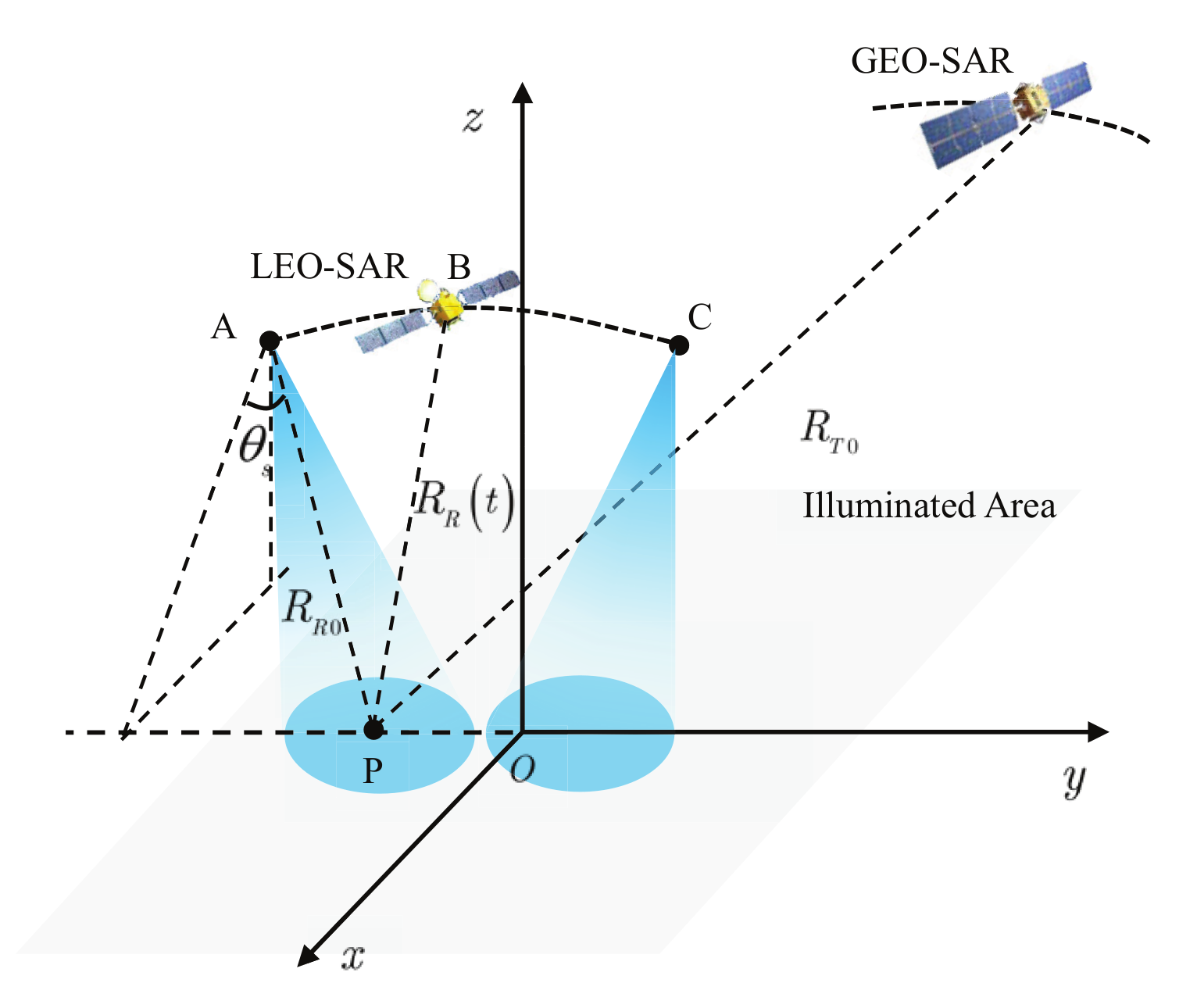
Figure 1. Imaging geometry of GEO-LEO BiSAR in RTLC.
Remotesensing 14 03178 g001
Figure 2. Illustration of propagation path for GEO-LEO BiSAR.
Remotesensing 14 03178 g002
Figure 3. Bistatic range errors of the competing range models.
Remotesensing 14 03178 g003
Figure 4. Bistatic range and phase errors of BiCoT-ESRM.
Remotesensing 14 03178 g004
Figure 5. Flowchart of the proposed imaging algorithm for GEO-LEO BiSAR in sliding-spotlight mode.
Remotesensing 14 03178 g005
Figure 6. Positions of nine targets.
Remotesensing 14 03178 g006
Figure 7. Imaging results of the nine point targets by the proposed method based on BiCoT-ESRM.
Remotesensing 14 03178 g007
Figure 8. Imaging results of the nine point targets by the ‘non-stop-and-go’ RMOSE.
Remotesensing 14 03178 g008
Figure 9. The residual higher-order phase of the imaging area.
Remotesensing 14 03178 g009
Figure 10. Azimuth resolution of GEO-LEO bistatic SAR and the equivalent experiment.
Remotesensing 14 03178 g010
Figure 11. Spatial variance of GEO-LEO bistatic SAR and the equivalent experiment.
Remotesensing 14 03178 g011
Figure 12. Imaging result and corresponding optical image of the equivalent experiment by the proposed method. The imaging swath width is 1.1 km × 1 km. (a) Imaging result of the equivalent experiment. (b) Optical image of the scene.
Remotesensing 14 03178 g012
Figure 13. Imaging result of the equivalent experiment by ‘non-stop-and-go’ RMOSE method.
Remotesensing 14 03178 g013
Figure 14. Comparison of azimuth and range profiles for the selected isolated strong target. (a) Azimuth profile of the proposed method. (b) Range profile of the proposed method. (c) Azimuth profile of the ‘non-stop-and-go’ RMOSE method. (d) Range profile of the ‘non-stop-and-go’ RMOSE method.
Remotesensing 14 03178 g014
Table 1. Simulation parameters of sliding-spotlight GEO-LEO BiSAR.
System Parameters
Carrier fraquency5.4 GHzData take duration18 s
Signal bandwidth240 MHzPRF5000 Hz
Pulse width45 μsRotation distance1146 km
Azimuth beam rotation rate0.37°/sReceiver slant range990.4 km
Receiver azimuth beamwidth0.58°Bistatic angle32.4°
Orbit Parameters
PlatformGEOLEO
Orbit altitude35,786 km754 km
Eccentricity0.0030.0009
Inclination20°98°
Incidence angle43.9°41.2°
Look angle36°
Location(8874, −24, 113, 26,908) km(609, 235, 745) km
Velocity(−2661, −979, −0) km(0, 7400, 1071) m
Scene center(0, 0, 0) m
Table 2. Measured imaging metrics of the nine point targets by the proposed method based on BiCoT-ESRM.
Target IndexAzimuthRange
ρ a (m)PSLR (dB)ISLR (dB) ρ r (m)PSLR (dB)ISLR (dB)
10.68−13.28−10.11.01−13.25−10.4
20.69−13.33−10.21.01−13.33−10.4
30.68−13.26−10.11.02−13.32−10.4
40.68−13.25−10.21.01−13.28−10.4
50.68−13.25−10.11.01−13.29−10.4
60.68−13.27−10.11.01−13.29−9.5
70.68−13.28−10.11.02−13.32−10.4
80.68−13.30−10.41.01−13.36−10.5
90.69−13.31−10.11.01−13.33−10.4
Table 3. Measured imaging metrics of the nine point targets by the ‘non-stop-and-go’ RMOSE.
Target IndexAzimuthRange
ρ a (m)PSLR (dB)ISLR (dB) ρ r (m)PSLR (dB)ISLR (dB)
10.91−3.60−1.51.01−13.24−10.5
20.78−5.85−3.51.01−13.24−10.4
30.78−5.78−4.11.01−13.29−10.4
40.76−6.50−4.21.01−13.35−10.5
50.72−10.68−8.11.01−13.29−10.4
60.71−7.62−7.11.01−13.30−9.8
71.07−2.80−0.71.02−13.39−10.4
80.73−6.09−4.11.01−13.32−10.4
90.75−5.9−4.21.01−13.33−10.4
Table 4. Parameters of the equivalent experiment.
System Parameters
Carrier fraquency5.4 GHzData take duration6 s
Signal bandwidth240 MHzPRF3714 Hz
Pulse width45 μsRotation distance1091.1 km
Azimuth beam rotation rate0.387°/sGF-3 slant range844.4 km
GF-3 azimuth beamwidth0.678°Bistatic angle23.2°
Plarform Parameters
PlatformGF-3Stationary receiver
Platform altitude754 km69 m
Incidence angle28.3°86.6°
Initial position(73.8, 39.3, 74.3) km(−155, 693, 69) m
speed(7434, −1463, −5) km(0, 0, 0) m
Isolated strong target location
location(0, 0, 0) m
Table 5. Comparison of focusing results between proposed and ‘non-stop-and-go’ RMOSE method.
MethodAzimuthRange
ρ a (m)PSLR (dB)ISLR (dB) ρ r (m)PSLR (dB)ISLR (dB)
proposed method0.99−14.97−9.680.81−9.25−7.28
’non-stop-and-go’ RMOSE method1.67−13.95−8.990.83−11.07−7.08
Publisher’s Note: MDPI stays neutral with regard to jurisdictional claims in published maps and institutional affiliations.