1. Introduction
Impact craters are the most significant dominant features on the Moon’s surface, which record the history of the Solar System, and have been one of the research hotspots in recent years [
1,
2,
3]. In the geosciences field, the study of lunar impact craters can be divided into three aspects. First, the geological history can be examined by crater densities, and the relative chronology of a region can be assessed remotely [
4,
5]. Secondly, the morphological and structural characteristics of the impact craters can be deduced from different degrees of erosion and damage caused on the Moon’s surface by internal forces [
6]. Thirdly, the temporal variation in cratering rates can provide reference for studying the mechanism and dynamics of the craters [
7,
8]. In the aerospace field, impact craters can be used as the landmark for autonomous navigation and safe landing of spacecraft. Thus, how to quickly and effectively identify lunar impact craters is of great significance in planetary studies.
The typical characteristics of a crater include differences in diameter on the scale of orders of magnitude, large variations in shape due to overlapping or filling and variable and complex morphologies [
9]. After obtaining these parameters, the spatial aggregation and distribution characteristics of impact craters can be further analyzed comprehensively. Therefore, delineating the location and size of impact craters is the basis of studying aggregation and distribution problems. Previous researchers have attempted to carry out crater detection either manually or automatically by visual inspection of images. Two-dimensional geometric algorithm mainly starts from the light or shadow part of the image and carries out topological calculation according to the feature of the elements [
10,
11,
12]. Remote sensing technologies such as object-oriented and texture analysis are aimed to select appropriate feature information for automatic identification of impact craters combined with the target features of remote sensing images [
13,
14,
15]. The methods of computer-oriented image processing have been developed to automate the process of classifying craters, including edge detection, Hough transforms, and support vector machines [
16,
17,
18]. All of the above approaches are not practical for vast numbers of kilometer- and sub-kilometer-sized craters on the Moon. In addition, manual crater counting by experts can be affected by many subjective factors, resulting in several disagreements [
19,
20,
21].
A newly developed automatic detection method based on machine learning can also be used to determine the large extent characteristic of craters from the general feature of craters [
22]. Deep learning, a branch of machine learning, has showed fast and accurate performance based on huge amounts of detected craters as labelled samples [
23,
24,
25]. The authors carried out the crater identification on digital elevation map (DEM) images of the Moon and also used transfer learning method from the Moon-trained convolutional neural networks (CNNs) to identify the impact craters on Mercury [
25]. The results showed the viability of using CNNs to determine the positions and sizes of craters from Lunar DEMs. However, some DEM anomalies may not be related to impact craters, which will inevitably lead to wrong results in the automatic identification process [
25]. Furthermore, some craters cannot be showed on DEMs due to the effect of overburden. The high coverage and spatial resolution of gravity data acquired by the Gravity Recovery and Interior Laboratory (GRAIL) mission reveals the gravitational response of the distribution of impact craters, providing an opportunity to understand the lunar surface [
26].
2. Motivation
Gravity anomalies on the Earth are related to the density differences generated by tectonic movements over local and large areas. However, the main structural features on the Moon are characterized by large and numerous impact craters. Lunar impact craters have obvious responses to circular gravity anomalies. This makes it possible to identify impact craters by using gravity anomalies. The gravity anomaly has good lateral resolution and can effectively extract the boundary of the geologic bodies with different density contrasts. The identification of impact craters on the Moon and other planetary bodies is of great significance to studying and constraining the dynamical process and evolution of the Solar System. Traditionally, this has been performed through visual examination of images. Due to the effect of overburden, some structural features cannot be effectively identified from optical images, resulting in limitations in the scope, efficiency and accuracy of identification. Thus, the gravity anomaly can provide the additional support for the identification of lunar impact craters.
Most of the previous automatic detection methods focus on the direct processing of images (i.e., DEM data). These processing branches include image feature enhancement, edge detection, feature extraction with filtering, gaining, mathematical transform and so on. Due to the size and shape variations of impact craters, as well as noise existence in image data sets, the related methods will have the problems of time-consuming computation and artifact appearance. On the basis of machine learning, we can deeply learn the main features of the local image from the training data sets, so as to realize the effective feature detection of the global image. The two aspects of machine learning applications, target detection and semantic segmentation, have achieved great success in the past decade. Therefore, deep learning (i.e., U-net architecture) can be viewed as an alternative way to realize the feature detection of lunar impact craters.
In this paper, our aim is to develop an effective approach on the custom U-net known as CNN architecture to automatically and precisely identify impact craters from the GRAIL gravity map. Firstly, we introduce the architecture of U-net and then propose a workflow for the identification of impact craters by using U-net on GRAIL gravity map. Then, we employ three well-known metrics to evaluate the performance of the crater identification. Next, we compare the proposed identification method with the previous studies, and summarize the advantages and disadvantages of the method. We also discuss the identification results of two hotspot basins, which obtained satisfying performance. The proposed method can still achieve the same quality for the identification of the impact craters from the gravity anomalies of GRAIL data under the condition that the resolution of the GRAIL gravity data is not superior.
3. Data
The GRAIL mission was designed to create the most accurate gravitational map of the moon to date [
26,
27]. It can provide insight into the Moon’s internal structure, composition and evolution when it is combined with topographic data. The published data sets of the GRAIL mission include the radius of the celestial body, the universal gravitational constant, the mass of the celestial body and the series and orders of spherical harmonic model. The gravity anomaly at the specified observed point can be calculated by:
where V means gravity anomaly, and ρ, θ and λ are sagittal diameter, polar distance and longitude of the calculated point, respectively, GM means the product of gravitational constant and lunar mass, referred to as the lunar center gravitational constant, C
mn and S
mn are spherical harmonic function coefficients of the gravitational potential, α means lunar long radius and P
mn(cosθ) represents Legendre function, where n and m mean order and degree, respectively.
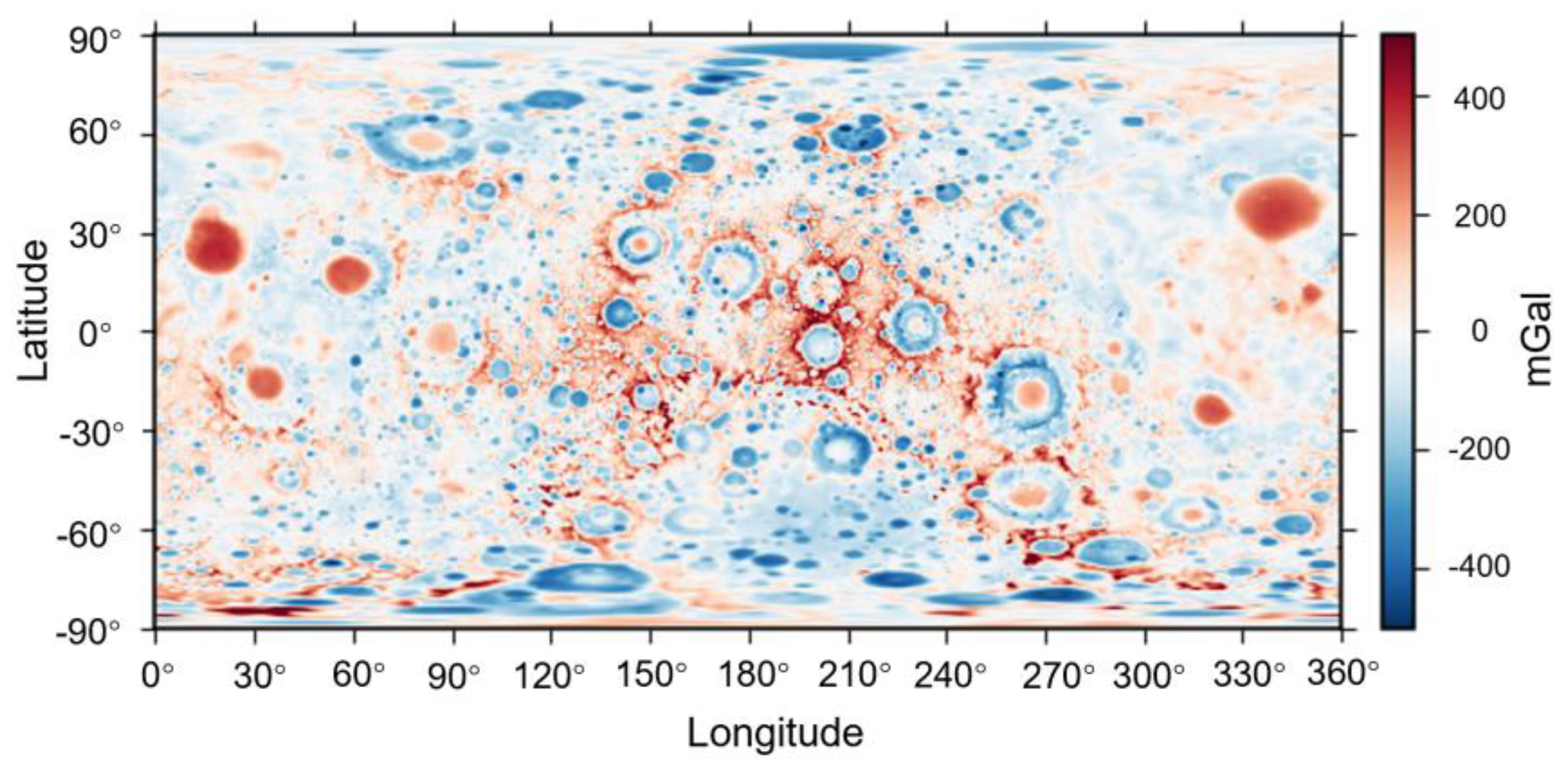
In this study, we select the 1500-order spheric harmonic data published in 2016, and then expanded gravity and potential fields incluing the gravitational effect of finite-amplitude topography [
28], which is shown in
Figure 1.
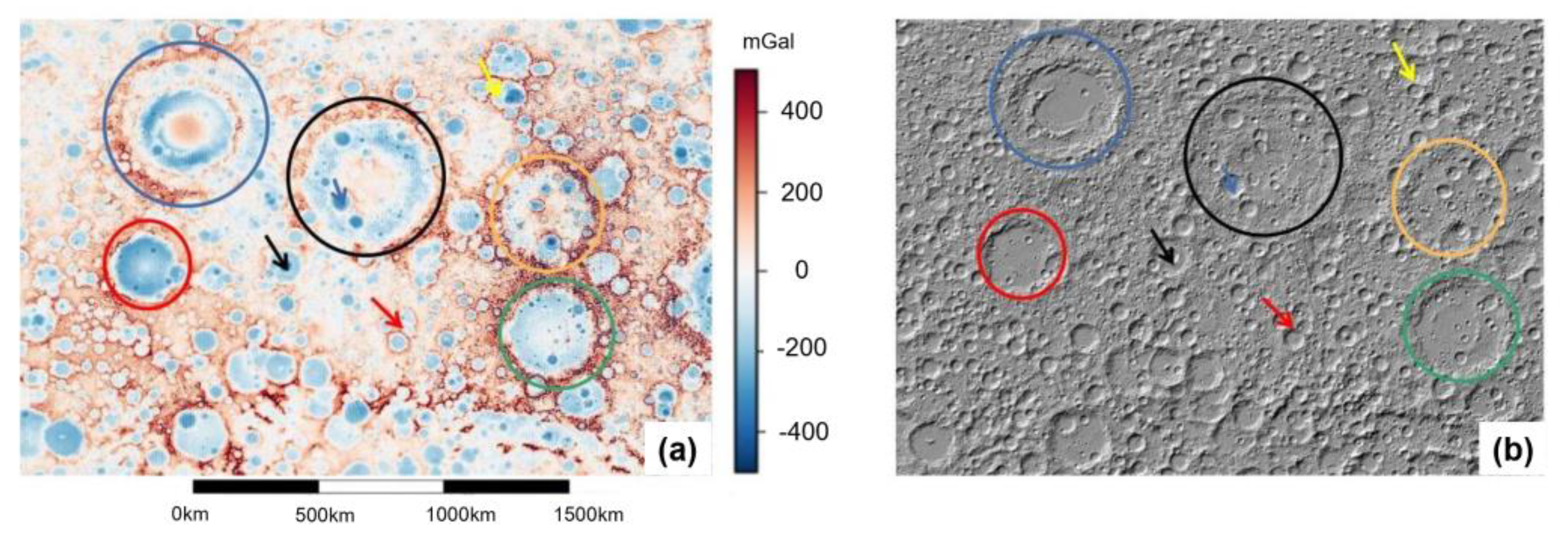
The size of the gravity anomaly map is 3656 × 1824, and the resolution is 10 pixel/degree or 2.98 km/pixel. The map shows many gravity anomalies, which may be consistent with the characteristics of the impact craters. In order to determine whether the processed gravity anomaly map can correctly reflect the location and shape of impact craters, we cut down the small part of
Figure 1 and compare it with the corresponding part of laser allocator data obtained by LRO detector (shown in
Figure 2). The resolution of the LRO data is about 100 m per pixel. As shown in
Figure 2, the feature profiles in GRAIL gravity map are roughly consistent with the profiles in LRO altimetry data. Therefore, this source data of the GRAIL gravity can be used as the data set in the process of subsequent deep learning.
The processing data sets are formed by manually delineating the gravity anomalies of impact craters in the GRAIL gravity map. The position and morphology of the anomaly are determined by two points. One is the coordinate of the center of the anomaly, and the other is one point on the edge of the anomaly. Anomalies caused by independent and well-characterized impact craters can be delineated manually. However, for those areas that have been subjected to multiple meteorite impacts, multiple superimposed anomalies need to be compared with high-precision DEM images before delineation, which is more dependent on the operator’s subjective experience. In addition, due to the image accuracy, some gravity anomalies with pixel diameters less than 6 pixels are difficult to reflect the above features, so they are temporarily omitted. The source data can be added to further improve model performance after the accuracy of the source data is improved. After manual detection and delineation after above considerations, a total of 910 usable anomalies were identified, classified by diameters as shown in
Table 1.
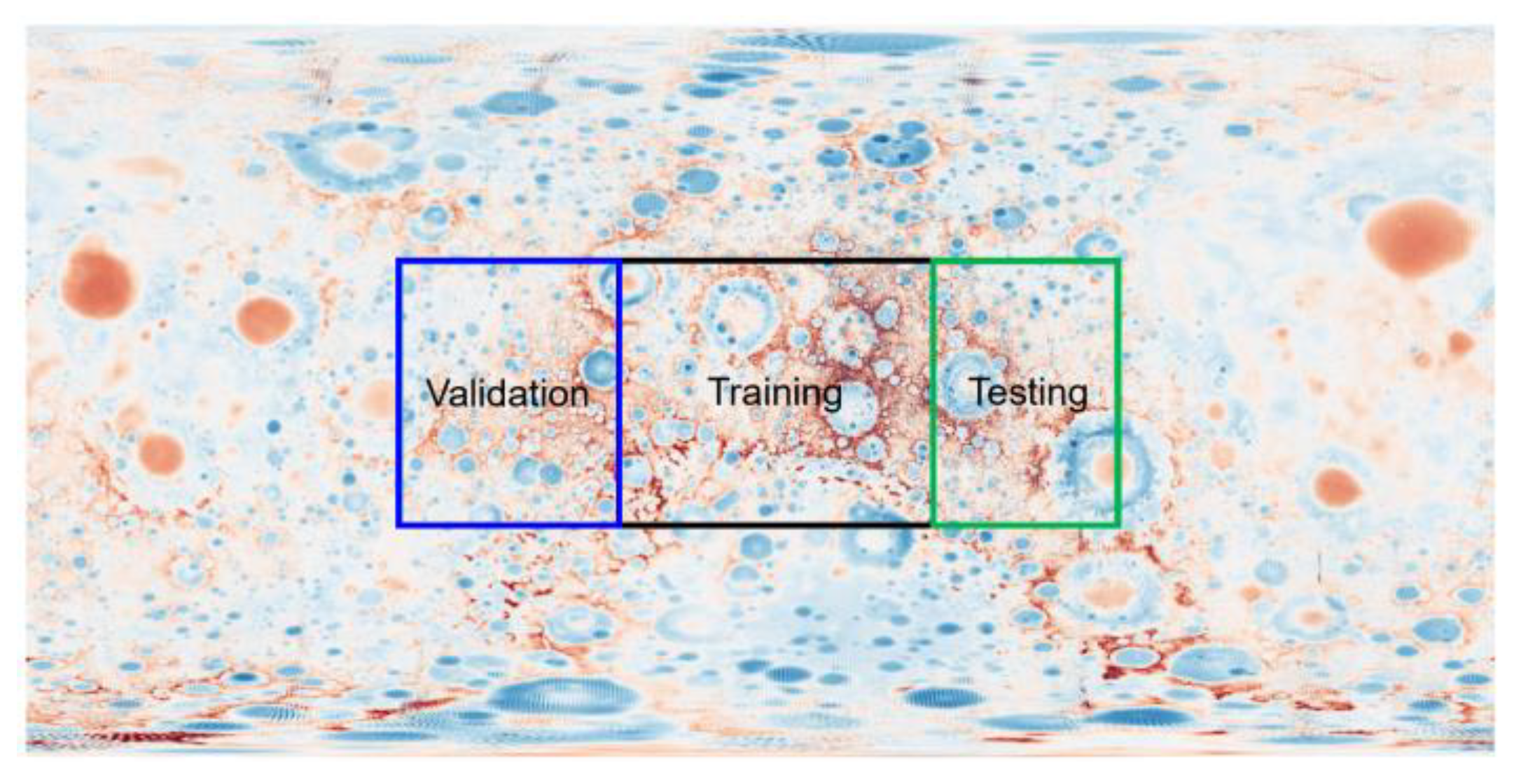
The data sets are mainly divided into three parts: training, validation and testing. The training data sets are used for initial training and model fitting. The validation data sets are used for the preliminary evaluation of the above training model. Then, the model parameters are adjusted based on the evaluation results, making the fitting results better. The validation data sets are used for the final evaluation of the model. The evaluation results no longer affect the model parameters. Three types of data sets are tailored from different regions in this study, as shown in
Figure 3. The training data sets are selected from the black rectangle determined by the diagonal connection from 35° E 35° N to 35° W 35° S. The validation data sets are selected from the blue rectangle determined by the diagonal connection from 80° W 35° N to 35° W 35° S. The testing data sets are selected from the green rectangle determined by the diagonal connection from 35° E 35° N to 80° E 35° S. The anomaly information of three types of data sets can be found in
Table 2.
4. Methods
We split our input image/output target pairs into three separate datasets to be used for training, validating and testing our CNN. The U-net architecture was used as the CNN platform. To solve the classifier issues with high-efficiency processing, we utilized binary-cross entropy function and Adam optimizer. We employed three well-known metrics to evaluate the U-net performance of the crater identification in order to compare it with other methods proposed by previous authors.
4.1. U-Net Architecture
U-net was proposed in 2015 and was first applied to medical image segmentation tasks [
29]. Subsequently, U-net has been widely used in image segmentation tasks in various fields, and many U-net segmentation models have been derived so far. U-net is a typical Encoder–Decoder structure. This architecture consists of a contracting path (left side shown in
Figure 4) and expansive path (right side shown in
Figure 4), connected by multi-level skip connections (middle) to denote the feature extraction and up-convolution stages of the network. The input into the contracting path can be the GRAIL gravity map, and the ouputs are the predictions from a final layer following the expansive path [
29]. Unless otherwise stated, all convolutional layers have banks of filters. Each filter applies 3*3 padded convolutions followed by a rectified linear activation unit (ReLU). The ReLU function can be written by f(z) = max(0,z).
As shown in
Figure 4, the contracting path contains 3 convolutional blocks. A block here includes two convolutional layers followed by a max-pooling layer with a 2 × 2 pool size. Each convolutional layer in blocks 1, 2 and 3 include 112, 224 and 448 filters, respectively. The role of the convolutional layer is to extract feature information of the target. The convolutional layer at a shallow position in the network can only extract low-level features, such as edges, lines, angles, etc., while the convolutional layer at a deep level can extract more complex features on the basis of the shallow level [
29].
The expansive path also contains 3 convolutional blocks. One convolutional block consists of two convolutional layers, an up-sampling layer, a dropout layer and a concatenation with the corresponding block from the contracting path. The main function of the convolution layer is to reconstruct the image according to the feature processed by the down-sampling layer. The final output image has the same size as the input image, but the “target feature” of the original image is more prominent. The principle of the up-sampling layer is relatively simple, which is to enlarge the image size by copying the current pixel value and expanding to the surrounding operation. The dropout layer is used to prevent the model from overfitting. If there are too many model parameters and too few training data, the training model will be over-fitting. The over-fitting model has good recognition accuracy for training data sets but poor recognition effect for uncontacted test data sets. The dropout operation causes all nodes in the hidden layer to fail with a certain probability. If the dropout value is set to 0.5, assuming that there are 100 nodes in a certain layer, only 50 nodes will have effective output information during training. It can be understood as reducing the dependence of the model on training data. In addition, the dropout layer can limit the range of weights so that if the value of a weight exceeds the set value during training, the value of that weight defaults to the set value. The setting of dropout values depends on the researchers’ own experience. The concatenation layer is connected to the upper sampling layer. At the same time as the up-sampling, the network transmits the feature information through the concatenation layer, so that the up-sampling process combines the structural information of each layer.
4.2. Loss Function and Optimizer Selection
The loss function and the optimizer are important parts of the neural network. The loss function reflects the difference between the model output value and the actual output value, and it is also the most intuitive indicator for the dynamic evaluation of the model’s training quality. The smaller the value of the loss function, the better the quality of the model. At the beginning of network training, the loss function is usually large, so it is necessary to adjust the weight to reduce the value of the loss function output in subsequent training, and the tool for adjusting parameters is the optimizer. The loss function and optimizer used in the U-net designed in this paper are binary-cross entropy function and the Adam optimizer, respectively. The binary-cross entropy function can be denoted by
, where
y is the label (0 or 1), and
P(
y) is the predicted probability of the point being 1 for all
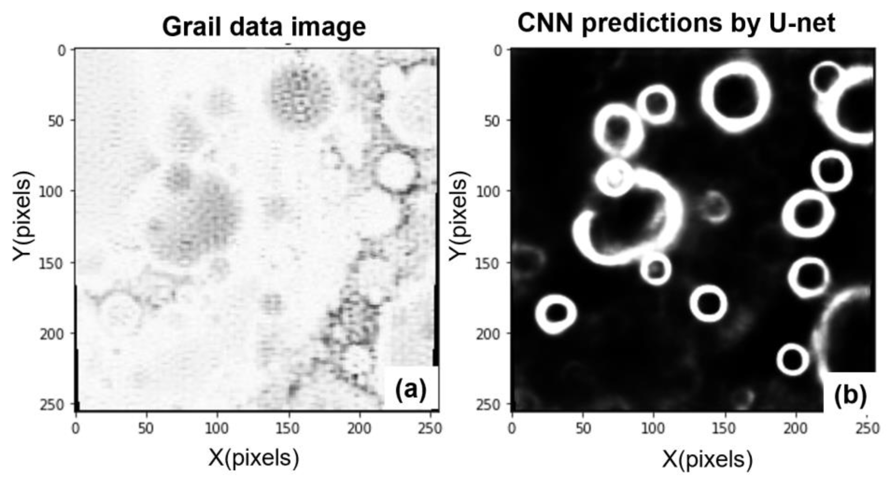
N points. The Adam optimizer adopts the first-order and second-order moment estimation of gradient variation to adjust the learning rate of each parameter dynamically, ensuring that the learning rate of each iteration has a clear range. Thus, the parameter changes smoothly and the Loss function decreases to the optimal direction with fewer computing resources. The data obtained after the designed network processing can better highlight the target features, which is shown in
Figure 5.
4.3. Training Details
A recurring phenomenon in machine learning is “overfitting”, which occurs when a model satisfies too many features which include overly complex and irrelevant elements during the training process [
29]. Overfitting models will have high accuracy on the training sets but low accuracy on new predicted data sets. Overfitting can be reduced and controlled by the penalization of overly complex models, restricting only essential characteristics from the training data sets. This penalization can be realized by the hyperparameters, which control the complexity of the training model. Regarding our U-net architecture, such hyperparameters consist of the weight regularizations for each convolutional layer, the learning rate, dropout layers after each merge layer, filter size, and depth of the network. These hyperparameters are tuned on a separate validation dataset, forcing the model to achieve high accuracy on two different datasets [
29]. The hyperparameters used in this paper are listed in
Table 3. The whole training flow chart can be expressed as
Figure 6.
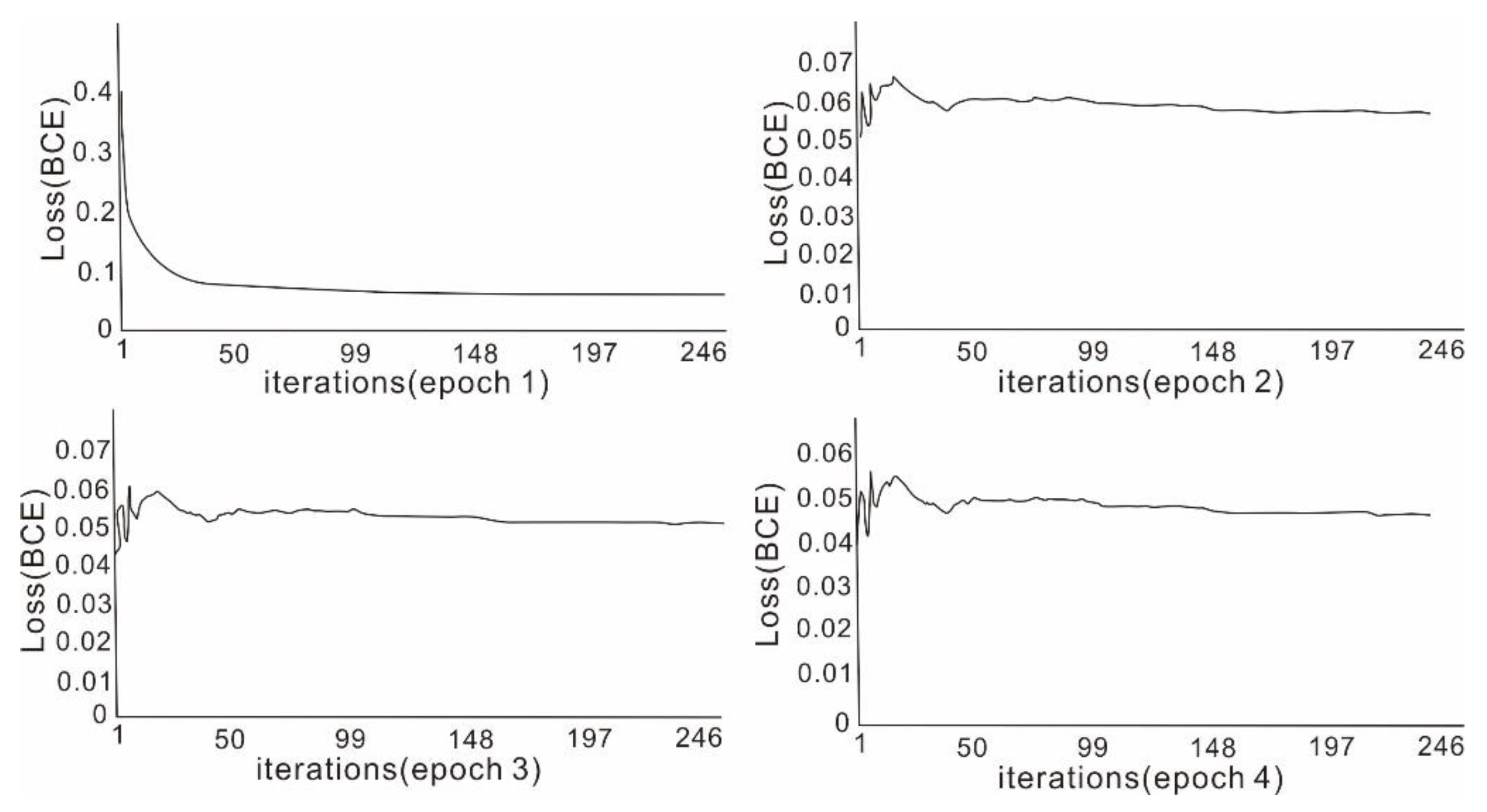
The changes in the loss function of the four-epoch processing are shown in
Figure 7. As shown in the figure, at the beginning of the first epoch, the loss function of the model was relatively high, reaching 0.4. As the training went on, the overall trend gradually decreased. By the end of the epoch, the loss function had dropped to about 0.06. The subsequent three epochs all showed repeated oscillations at the beginning, but the overall trend was still downward. By the end of the training, the loss function had decreased to about 0.04, indicating that the predicted output result of the model was highly consistent with the prior labelled output result, and the training was completed.
5. Evaluation and Discussion
We employ three well-known metrics to evaluate the U-net performance of the crater identification. These metrics method include the Precision, Recall and Accuracy. The Precision measures the portion of matched anomalies with respect to the prior-known reference map. The Recall denotes the percentage of matched anomalies from the anomalies identified by a computational method under our evaluation. The Accuracy means a combined metric that takes into account both Precision and Recall. Accuracy alone does not determine whether a designed model is good or bad. However, the combination of the Accuracy, Precision and Recall rate can be a good indicator of model performance. Specifically, the three metrics are defined as follows:
where TP denotes the true positive value, FP denotes the false positive value and FN denotes the false negative value. The larger an evaluation metric value is, the better the performance of the method is.
5.1. Comparison with Previous Studies
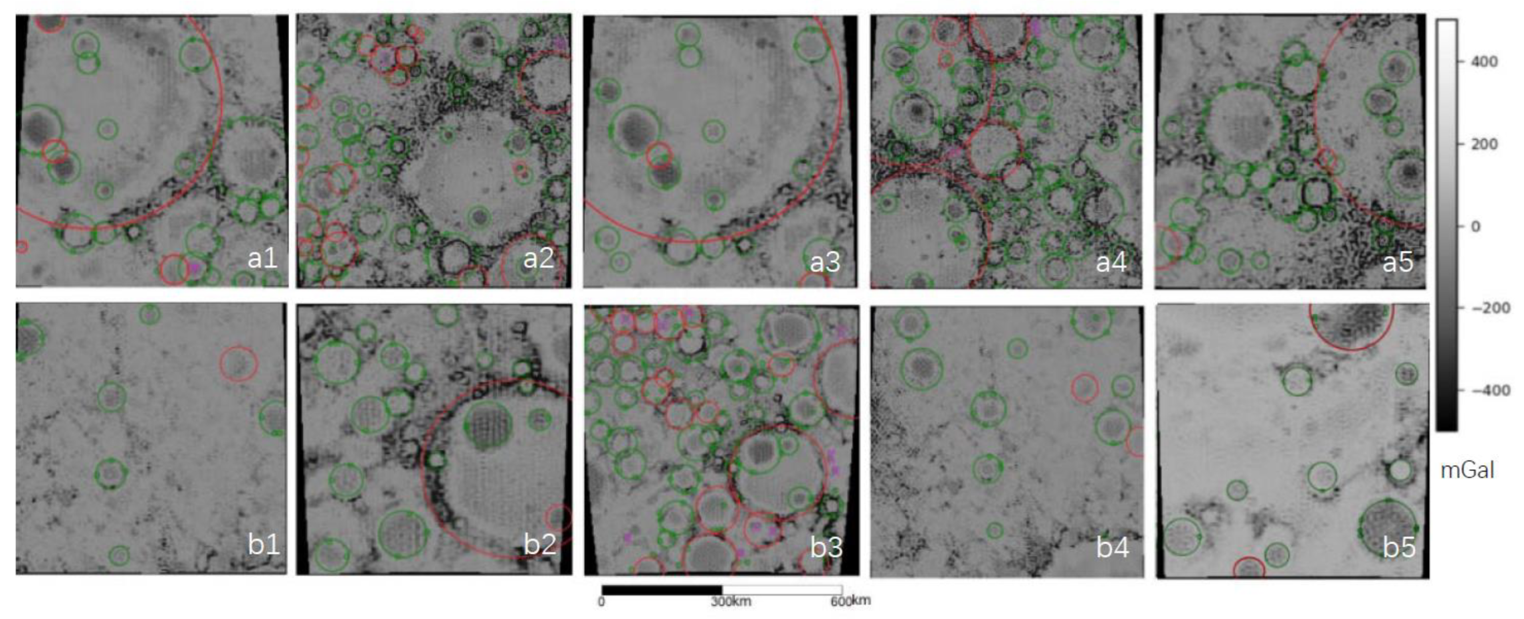
In this section, we compare the above-mentioned method with the previous studies, and summarize the advantages and disadvantages of the method. We randomly select parts of the gravity anomaly map to obtain multiple maps for deep learning. Next, we carry out crater identification and evaluate the results by using the above metrics. It includes both the part in the data set area (referred to as Class 1,
Figure 8(a1–a5)) and the part outside the data set area (referred to as Class 2,
Figure 8(b1–b5)). Some abnormal contours of the selected maps appear independent and obvious, whereas others have the characteristic of multiple and complex superpositions. Thus, the test results can cover various situations and are more representative.
From the testing results of the 10 randomly selected maps, we know that the average Accuracy is 0.8, with a relatively scattered distribution. Both Class 1 (From
Figure 8(a1–a5)) and Class 2 (From
Figure 8(b1–b5)) show excellent (>0.9) results and poor (0.5~0.7) results, indicating that the method we proposed basically avoids the problem of over-fitting and may not obtain good results only for the existing data sets. In addition, it can be found that whether Class 1 or Class 2, most of the maps with high Accuracy value have obvious features with few phenomena of multiple abnormal superposition. The images with low Accuracy values basically have some abnormal superpositions, resulting in complex feature profiles that are difficult to be identified. The Recall rate of 10 maps also show similar characteristics, which is also related to the features and distribution of the anomalies. In terms of Precision, the results of the 10 maps are very good, most of which are above 0.9, indicating that the proportion of correct samples is very high among the samples with positive prediction results. The main reason for the reduction in the evaluation metrics is that the FN is too high, with the result of “missing detection”, and FP is too low with the result of “error detection”.
In order to reflect the feasibility and advantages of this method, we also compared it with previous studies (
Table 4). We found that it is difficult to find a relevant study on the impact crater identification on lunar gravity data. Therefore, most of the methods selected for comparison are based on satellite images. The data resolution of satellite images is much higher than that of gravity data, which can reach the level of 100 m/pixel. However, the accuracy of the gravity data used in this study is only 2.98 km/pixel, and the amount of data available is relatively small. Five methods in previous studies are selected for comparison, including the AdaBoost method (referred to as ①), the Faster R-CNN method (referred to as ②), the detection method based on shadow and texture features (referred to as ③), the feature detection based on multi-scale topography data (referred to as ④) and automatic detection based on DEM data (referred to as ⑤). The test results of the above five methods are listed in
Table 4. We select three different images for testing by Method ①, which contain more than 100 impact craters with different distribution complexities (shown in
Figure 9). The image with simple features and independent distribution has the best testing result, while the image with complex features and overlapping distribution has the worst testing result, which has the same deficiency as this study. Method ② lists the range of the testing results from four regions. Numerically, the identification quality is similar to that of this study. The testing results of methods ③ and ④ are obviously better than those used in this paper. However, these testing maps have excluded the complex features, overlapping distribution and degenerate impact craters, which belong to the better results under relatively ideal conditions. Considering the various complex situations to be dealt with in practical application, the method used should be thoroughly tested to discover the advantages and disadvantages. Method ⑤ only gives a recognition accuracy of 83%, and other metrics are not given. Compared with these five methods, this study has higher accuracy and precision, and middle recall rate. The quality of the model is better than the above five methods. However, it should be noted that the expected recognition targets of this method include both independent and well-characterized anomalies and complex anomalies with multiple superposition, so the testing is relatively comprehensive. Due to the limitation of the accuracy of the original image, the training samples produced in this study are few, and the overall characteristics of the anomalies are complex in the process of the model training. Good detection results have been achieved, indicating that CNNs can obtain high-quality output models by learning a small amount of data sets.
5.2. The Identification Results of the Study Hotspots
5.2.1. Wugang Basin
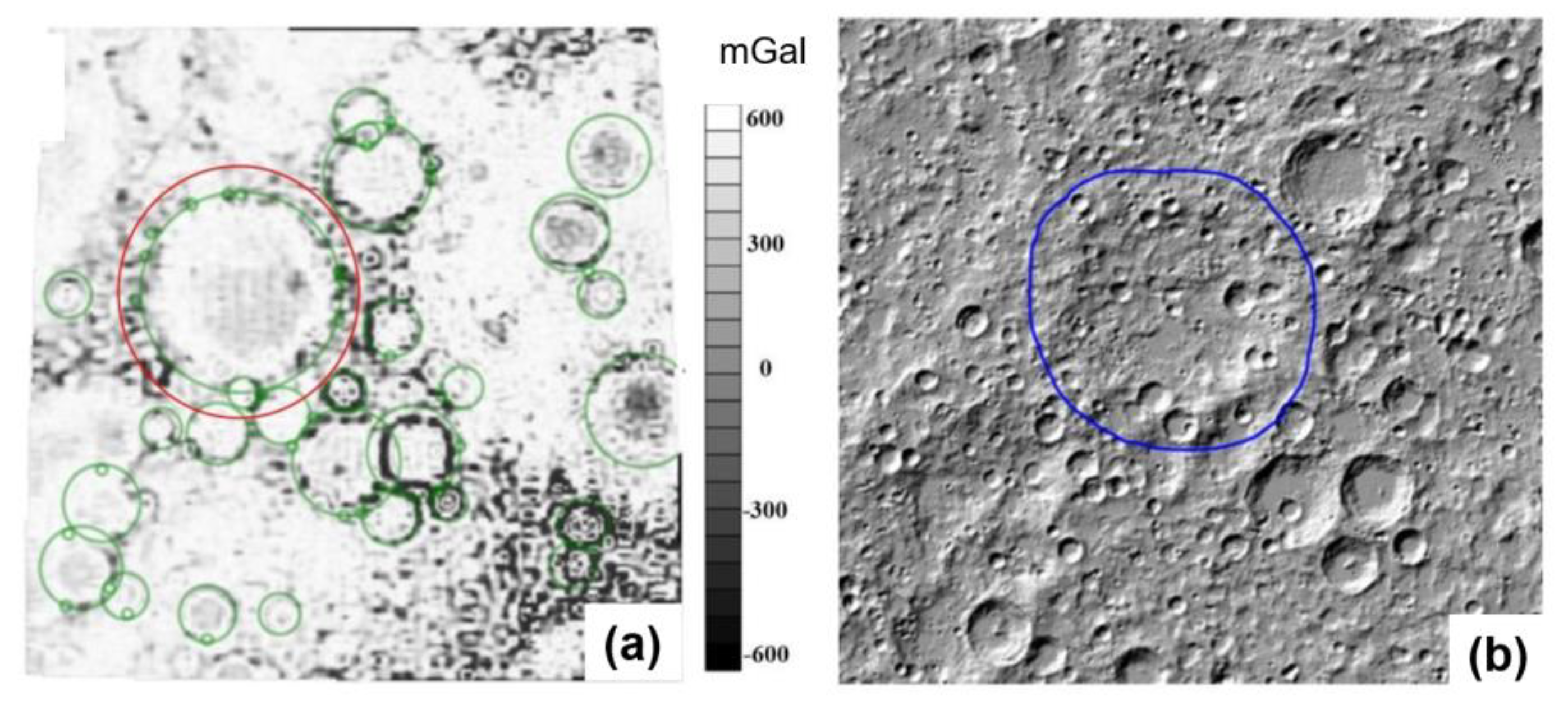
Huang et al. discovered and named the Wugang impact crater through the CLTM-s01 altimetry model of “Chang’e-1” in 2009 [
31]. The shape of the impact crater on the DEM map is shown in
Figure 10b with a blue circle. In this study, the designed U-net network was used to identify the impact craters from the gravity anomaly in this area and the profile of the gravity anomaly generated by the Wugang impact crater was successfully circled (
Figure 10a). The region of the Wugang impact crater was subjected to several meteorite impact events after its formation. Therefore, the shape of the Wugang impact crater has been severely damaged, which was not well recognized on DEM maps. However, the circular contour edge of the crater is still shown from the gravity anomaly map. This enables us to adopt the U-net architecture to identify the shape of impact craters from gravity anomaly map.
5.2.2. Archimedes Circle Mountain
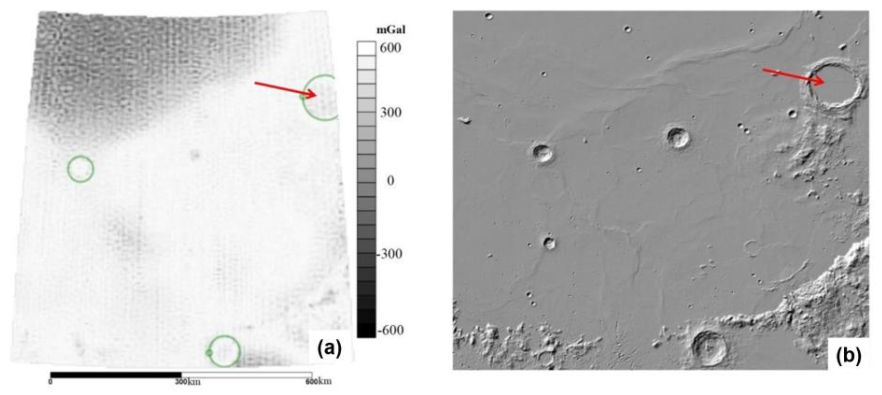
Archimedes Circle Mountain is a large impact crater located at the edge of the Rain Sea on the front of the moon [
32]. The surface inside the impact crater was covered by magmatic rocks, and there is no central peak in the crater. The magmatic rocks in the crater show that the crater itself was formed 3.1 billion years ago, when the Yuhai impact basin was completely filled with lava. Therefore, the geological age of the crater can only be 3.8~3.1 billion years ago; that is, the Archimedes crater was formed in the late Yuhai epoch. This judgment process is an application example of the superposition principle in geology.
It can be seen from
Figure 11 that the U-net model accurately circles the anomalies generated by Archimedes impact crater, which have relatively simple features and no interference from other superimposed anomalies around, and thus are relatively easy to be detected.
5.3. The Identification Evaluation of the Full Map
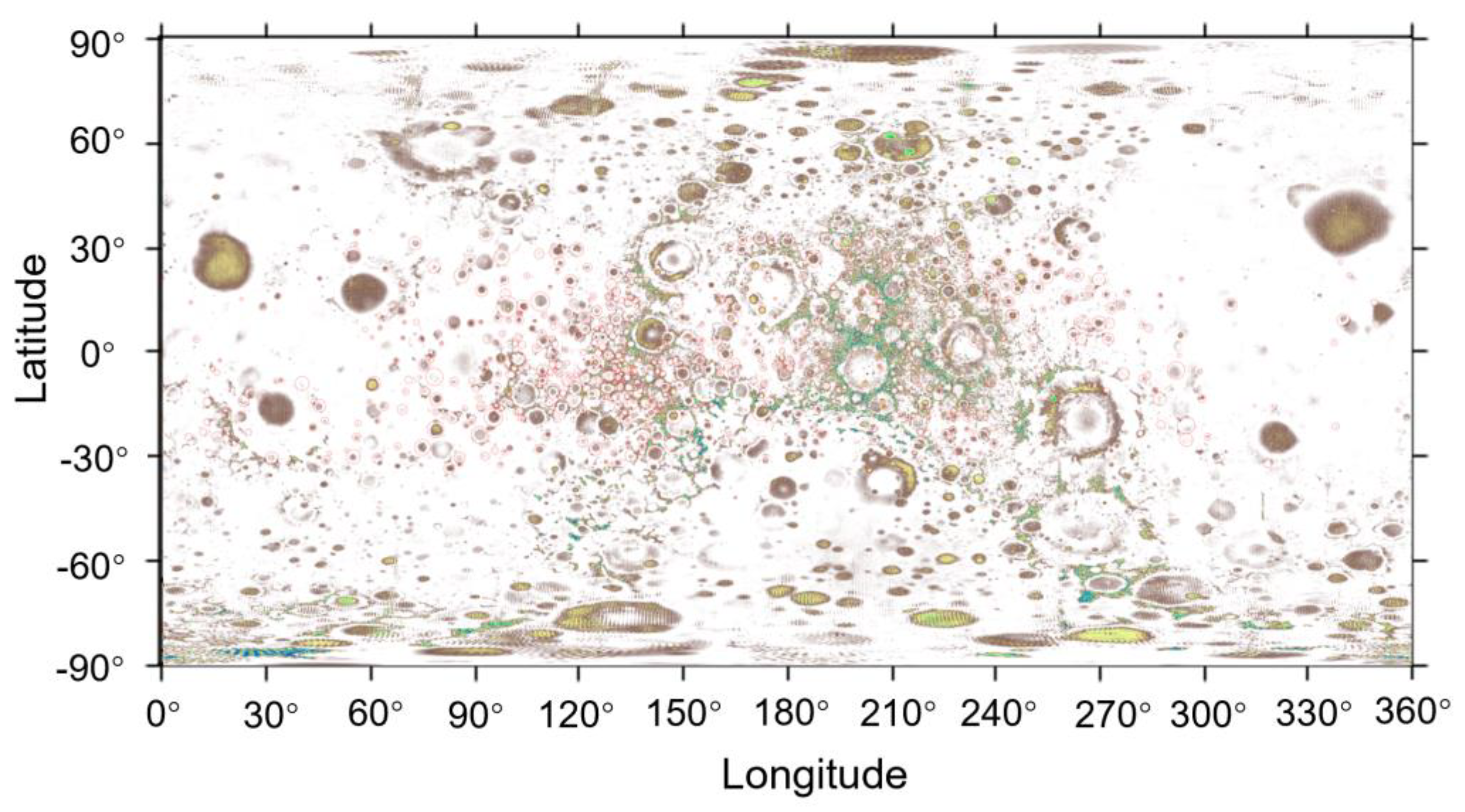
After proving the feasibility and advantages, we applied the CNN-based training model to the impact crater detection from the full Lunar GRAIL gravity map. The detection results are shown in
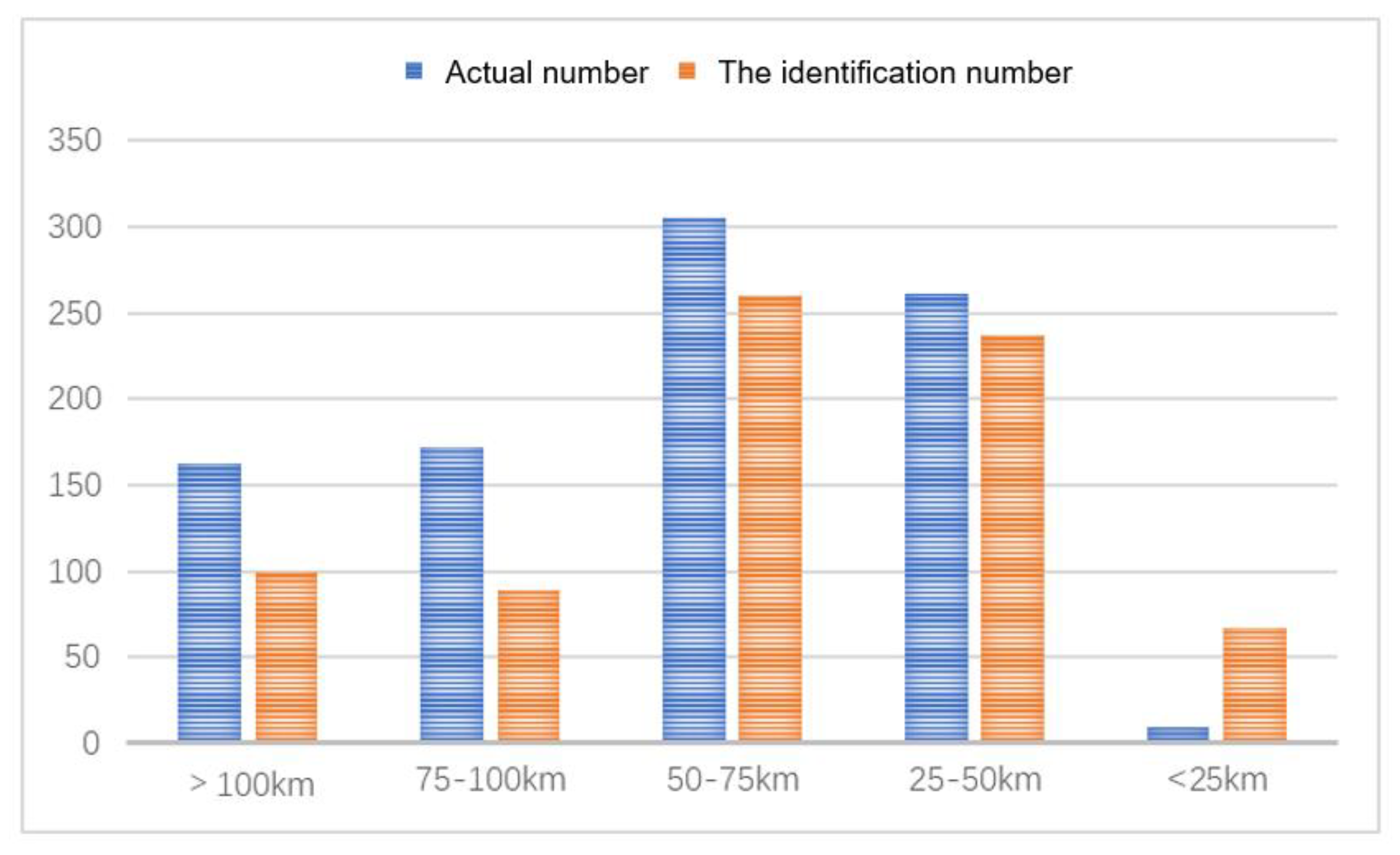
Figure 12. Gravity anomaly features of impact craters are classified according to their diameters. A statistical histogram is used to evaluate the identification effect of U-net on the anomalies of different sizes, which is shown in
Figure 13.
In this study, the anomalies are divided into five parts according to the diameter, which are <25 km, 25~50 km, 50~75 km, 75~100 km and >100 km. As shown in
Figure 4,
Figure 5,
Figure 6,
Figure 7 and
Figure 8, the blue column is the actual number of anomalies within the size range, and the red column is the number of anomalies identified by U-Net. A total of 753 gravity anomalies caused by impact craters were identified by the U-Net model, accounting for 83% of the number of manually delineated 910 gravity anomalies. The overall identification effect is good. It can be seen from the figure that the anomaly detection effect in the intervals of 25~50 km and 50~75 km is relatively good, and the recognition degrees are 90% and 85%, respectively. Most of the gravity anomalies in these two parts are typical and intact, and only a few overlapping areas with multiple anomalies cannot be recognized. The detection effect of the other three parts is relatively poor, and the detection number of the range <25 km is even greater than the actual number.
6. Conclusions
The effective identification of impact craters is of great significance to the study of the evolution of the Moon and the whole Solar System. There are many problems in the field of the crater identification, such as relying too much on subjective experience, the heavy workload and low efficiency. In order to solve the above issues, this study proposes a method to automatically identify the impact craters from GRAIL gravity data by using the convolutional neural network. We have demonstrated the successful performance of CNNs in identifying the impact craters from GRAIL gravity data.
The ideal values of each hyperparameter in U-net architecture are determined after dozens of the model training testing and evaluation. The final model was evaluated by the loss function, with the low value of 0.04, indicating that the predicted output of the model reached a relatively high fitting degree with the prior labelled output. This also implies that the designed U-net has the ability to robustly identify the impact craters, especially when the features of the planetary surface on the impact crater are not trained.
We carry out the comparative analysis of different methods and obtain the detection results of the whole image. The results show that the proposed method has a clear detection of the target features. The detection accuracy of the partial tests is more than 80%, and the detection results of the whole image account for 83% of the total anomalies.
Compared with the previous methods, the results show that this method can still achieve the same quality for the identification of the gravity anomalies caused by impact craters under the condition that the resolution of the GRAIL gravity data is not superior. In addition, the target anomalies can be identified accurately in Wugang Basin and Archimedes Basin, indicating that the proposed method has great application potential.
Our current work only can identify impact craters with the range of roughly 15 km diameter, which is mainly due to the insufficient resolution of the gravity data. The data set selected in this study has the resolution of 2.98 km/pixel, and the gravity anomaly with a diameter of 15 km covers only 5–6 pixels, which affects the results of total feature detection of the craters and makes it impossible to identify all of them. However, as the instrument performance increases, the researchers will obtain gravity data with higher resolutions. Then, much smaller impact craters on the kilometer and sub-kilometer scales can be detected by the convolutional neural network, which can also be migrated to other celestial bodies for the study of the entire Solar System.
