Article

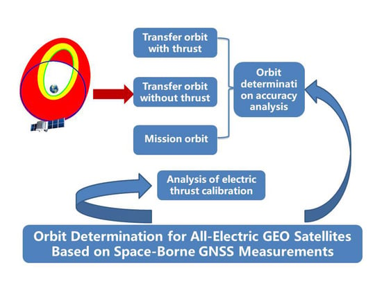
Orbit Determination for All-Electric GEO Satellites Based on Space-Borne GNSS Measurements

1
Shanghai Astronomical Observatory, Chinese Academy of Sciences, Shanghai 200030, China
2
National Satellite Meteorological Center, Beijing 100081, China
3
University of Chinese Academy of Sciences, Beijing 100049, China
4
Innovation Academy for Microsatellites Chinese Academy of Sciences, Shanghai 200135, China
*
Author to whom correspondence should be addressed.
Remote Sens. 2022, 14(11), 2627; https://doi.org/10.3390/rs14112627
Submission received: 7 February 2022 / Revised: 11 April 2022 / Accepted: 28 May 2022 / Published: 31 May 2022
(This article belongs to the Special Issue Space-Geodetic Techniques)

Abstract

:
Orbit accuracy of the transfer orbit and the mission orbit is the basis for the orbit control of all-electric-propulsion Geostationary Orbit (GEO) satellites. Global Navigation Satellite System (GNSS) simulation data are used to analyze the main factors affecting GEO satellite orbit prediction accuracy under the no-thrust condition, and an electric propulsion calibration algorithm is designed to analyze the orbit determination and prediction accuracy under the thrust condition. The calculation results show that the orbit determination accuracy of mission orbit and transfer orbit without thrust is better than 10 m using onboard GNSS technology. The calibration accuracy of electric thrust is about 10−9 m/s2 and 10−7 m/s2 with 40 h and 16 h arc length, respectively, using the satellite self-positioning data of 100 m accuracy to calibrate the electric thrust. If satellite self-positioning data accuracy is at the 10 m level, the electric thrust calibration accuracy can be improved by about one order of magnitude, and the 14-day prediction accuracy of the transfer orbit with thrust is better than 1 km.

Graphical Abstract

1. Introduction

GEO all-electric propulsion satellites completely rely on the electric propulsion system to change their orbits into the mission orbit after separation of the satellite and the rocket; they also use their electric propulsion system to maintain position after entering mission orbit [1,2]. Compared with traditional chemical propulsion control, electric propulsion technology has the advantages of long life, high specific impulse, widely adjustable range, simple structure, and high reliability, which can significantly reduce the mass of propellant carried by spacecraft, providing more capacity for payload and significantly enhancing economic benefits [3,4,5,6]. Early electric propulsion technology research and product development mainly targeted Low Earth Orbit (LEO) satellites and the north–south station-keeping of GEO satellites [7,8,9,10,11,12,13,14]. Due to the significant advantages of electric propulsion systems, research and practice of transfer orbit of GEO satellites and deep space exploration and other missions have been carried out successively [15,16,17,18,19,20,21,22,23,24]. A U.S. space exploration company realized the world’s first application of all-electric-propulsion GEO satellite on 1 March 2015; it carried four XIPS-25 ion electric thrusters on board and delivered the satellite into geostationary orbit after about 8 months of orbital transfer [25,26]. Due to the use of an electric propulsion system for orbital transfer, the weight of the satellite was reduced from 4 tons to 2 tons, and the launch cost was directly reduced by USD 50 million. Subsequently, many countries have successively achieved the practical application of electric propulsion platforms, and electric propulsion satellites have become an important direction for the development of geostationary satellites [27]. The SJ-9A satellite launched by China in 2012 is equipped with an LIPS-200 ion thruster and HET-40 hall thruster for on-orbit experiments to undertake the mission of maintaining north–south station keeping during the full life cycle of the satellite, which is the first space application of Chinese electric propulsion products [28,29,30]. In 2020, the LIPS-200 ion thruster electric propulsion system of the Asia–Pacific 6D satellite was used for north–south station keeping, which is the first commercial application of electric propulsion technology in China [31]. Chinese all-electric satellites will also be launched soon [32].
With the characteristics of real-time, high accuracy, and low cost, onboard GNSS orbit determination technology is currently the main technique for spacecraft autonomous orbit determination internationally [33,34,35]. In the past decades, GNSS-based orbit determination technology has been commonly used in LEO spacecraft, such as TOPEX, GRACE, NOAA, METOP, FY, HY, ZY, and GF, to provide real-time position or final precision orbit with an accuracy within 10 cm [36,37,38,39,40,41],which is largely attributed to the fact that LEO satellites provide continuous tracking and multi-directional observation geometry. In the field of high orbit spacecraft, GNSS receiving antennas pointing to the center of the Earth receive primary and secondary signals from navigation satellites on the other side of the Earth for orbit determination. Europe and the United States started earlier in this field and achieved operational applications on GOES-R meteorological satellites. In recent years, China has used CE-5T1 and GEO satellites such as SJ-17 and TJS-2 to validate GNSS orbit determination technology, and improved the accuracy of real-time orbit determination by 30 m [42,43,44,45,46,47,48,49,50,51,52].
Since satellites usually spend several months in transfer orbit before entering geostationary orbit by electric propulsion, during which frequent maneuvers are required according to the orbit design [53,54,55,56,57], this poses a new challenge for satellite precision orbit determination. However, previous studies on precision orbit determination have generally focused only on LEO and GEO satellites, and few papers have studied GNSS precision orbit determination for transfer orbits. In this paper, we study the ground orbit determination algorithm for an all-electric propulsion GEO satellite in transfer orbit and mission orbit by analyzing different conditions, and design an electric propulsion calibration algorithm to analyze its orbit prediction accuracy, which provides important support for the orbit control of all-electric-propulsion GEO satellite in transfer orbit and mission orbit.

2. Materials and Methods

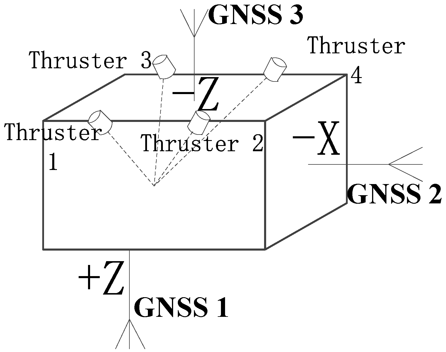
2.1. Satellite Electric Propulsion and Orbit Measurement System

Satellite use the electric propulsion system to realize orbit transfer and finally enter mission orbit. During the satellite orbit transfer process, the satellite goes through the initial orbit, the first stage of transfer orbit, the second stage of transfer orbit, and the final mission orbit. The changes in satellite height are shown in Figure 1. Firstly, the perigee and apogee of the satellite are all raised, and the apogee can reach up to 70,000 km in the first stage of the transfer orbit, while the optimal control strategy is adopted to finally transfer to the mission orbit in the second stage of the transfer orbit.
Four HET300 Hall electric thrusters are used in the electric propulsion system to realize the orbit control of the satellite. These are installed on the −Z side of the satellite, and the thrust direction of each thruster is through the center of mass of the satellite. The installation layout is shown in Figure 2.
The satellite adopts an all-electric-thrust orbit control strategy with a control period of 14 days. No thrust control is applied to the satellite during the satellite orbit determination period (the first day), and then satellite orbit control takes place over the next 13 days.
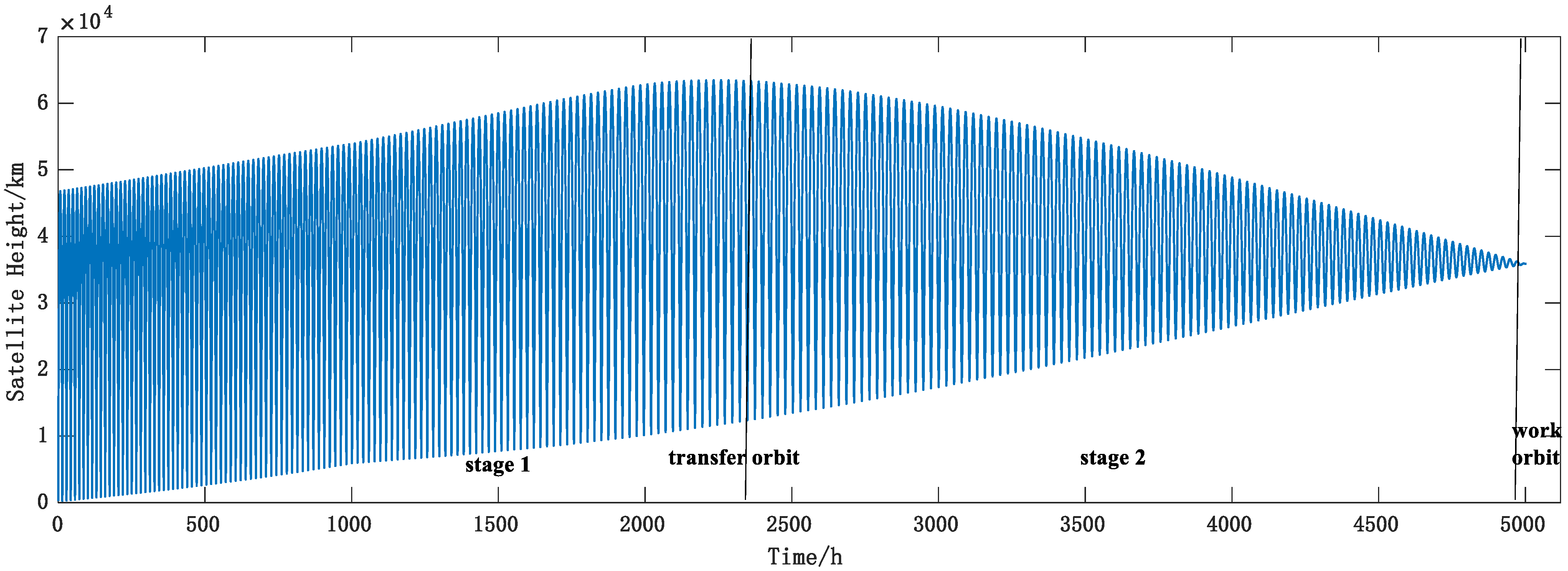
  • In the transfer orbit, the satellite adopts the orbit transfer control strategy, the perigee altitude is raised as soon as possible to cross the core region of the inner radiation belt in the first stage; the satellite is transferred to the mission orbit in the optimal transfer time in the second stage. The satellite thrusters are in mission state except for the ground shadow region during the satellite orbit control period.
  • In the mission orbit, the satellite adopts an orbit-holding control strategy. The satellite orbit is maintained at the target geographic longitude by applying thrust control at a specific orbital phase. The satellite thrusters are operated for no more than two hours per day during the satellite orbit control period.
The satellite carries only three GNSS antennas for orbit determination, and the installation layout is shown in Figure 2. Antenna 1 and antenna 2 are both high-gain antennas located in the +Z and −X direction of the satellite body-fixed system, receiving GNSS signals on the opposite side of the Earth. Antenna 3 is a low-gain antenna located in the −Z direction of the satellite body-fixed system, receiving GNSS signals overhead, which ensures that the satellite receives GNSS signals all the time in the transfer orbit and the mission orbit. GNSS receiver technical indicators are shown in Table 1.

2.2. Orbit Determination Principle

According to the theory of artificial satellite orbit [58], the motion equation of the satellite in the inertial coordinate system is as follows:
r ¨ = f 0 + f ε + f T h r u s t
where r is the position vector of the satellite in the inertial coordinate system, and the right end of the equation is the force acting on the satellite per unit mass; f 0 is the two-body force; f ε is the sum of the natural regenerative forces on the satellite, including the N-body regenerative force, the Earth’s non-spherical gravity, atmospheric drag, solar radiation pressure, etc.; f T h r u s t is the electric thrust force on the satellite.
The motion states r and r ˙ of the satellite at any moment t t 0 can be obtained from the motion states r 0 and r ˙ 0 of the satellite at initial moment t 0 . The solution of the motion equation is generally obtained numerically, and its initial conditions are:
r ( t 0 ) = r 0
r ˙ ( t 0 ) = r ˙ 0
Assuming that the electric thrust f Thrust has three directional components in the satellite body coordinate system: f x , f y , and f z . A thrust model is built in the satellite body coordinate system since the satellite thrust has a fixed direction (+Z), and the electric thrust is converted to the inertial system by attitude information and other force models (solar radiation pressure, gravity field, N-body). The M matrix is the conversion matrix from the satellite body coordinate system to the inertial coordinate system. Then
[ f 0 x f 0 y f 0 z ] = M · [ f x f y f z ]
Let the thrust parameter to be solved p = [ f 0 x ,   f 0 y , f 0 z ]. Because p is a constant, p = 0 . Let
X = [ r r ˙ p ] F = [ r ˙ r ¨ 0 ]
Then the kinetic equation can be written as
{ X ˙ = F ( X , t ) X   ( t 0 ) = X 0
where X is the state vector of the satellite at time t , and the partial derivative X ˙ of the satellite state quantity with respect to time is a function of the satellite state X at time t , called the state function, denoted as F   ( X , t ) . The state quantity X   ( t 0 ) of the satellite at time t 0 is recorded as X 0 . Linearize it:
{ x ˙   ( t ) = ( F X ) * x   ( t ) x   ( t 0 ) = x 0
where x   ( t ) = X   ( t ) X * ( t ) .
The observation equation can be written as:
Y = G   ( X , t ) + ε
where G   ( X , t ) is the true value corresponding to the observed data Y , and ε is the random noise of Y . After linearizing the above equation, it can be written as:
y = H x + ε
where H = ( G X ) * Φ   ( t , t 0 ) , Φ   ( t , t 0 ) is the solution of the following matrix differential equation:
{   Φ ˙     ( t , t 0 ) = ( F X ) * Φ   ( t , t 0 ) Φ   ( t , t 0 ) = I
The observed data are used to solve the optimal valuation of parameter X ^ 0 to solve the thrust parameter according to the motion equation. Assuming that a series of unequal precision observations ( y 1 , y 2 , , y N ) are obtained from time t 1 to t N with a covariance matrix R,
R = [ R 1 R 2 R N ]
It is known that the prior value of the state deviation x 0 at the initial moment is x ¯ 0 , and the prior covariance matrix is P ¯ 0 . Then
{ y = H x 0 + ε x ¯ 0 = x 0 + η 0
The following statistical characteristics are met:
{ E   ( ε i ) = E ( η 0 ) = 0 E   ( ε i ε j T ) = R i δ i j   ,     δ i j = 1 , i = j δ i j = 0 , i j   E   ( η 0 η 0 T ) = P ¯ 0 E   ( η 0 ε i T ) = 0
Under the above conditions, the linear unbiased minimum variance is estimated as
x ^ 0 = ( H T R 1 H + P ¯ 0 1 ) 1 ( H T R 1 y + P ¯ 0 1 x ¯ 0 )

3. Results

The orbit prediction accuracy of an all-electric GEO satellite in the mission and transfer orbit are analyzed using simulation data. Firstly, the “real orbit” is obtained based on the integration of the dynamics model, and then the simulated GNSS pseudorange and phase observation data with certain noise are obtained based on the GNSS navigation satellite precision ephemeris and clock difference products (from the Wu Han University (WHU) products of Multi-GNSS Experiment (MGEX), including GPS, BDS, and GLONASS, as shown in Table 2). The orbit of an all-electric GEO satellite determined from the simulated GNSS observation is compared with the “real orbit” to obtain the determination and forecasting accuracy.
GNSS signal visibility means the line of sight between the GNSS satellite and the receiver is not blocked by the Earth and the signal’s power at the receiver satisfies the signal capture tracking threshold when generating simulated observations. Thus, visibility analysis mainly considers two aspects: the geometric relationship among GNSS satellites, GNSS receiver antennas of the user satellite and the Earth, and whether the received signal power level meets the threshold. The angle of the main beam is different for the frequency and the generation (e.g., block III) of the satellite. For example, L-band antennas of GPS satellites can transmit L1, L2, and L5 with a three-frequency carrier antenna array, and the center of the antenna direction is aligned with the center of the earth, with main beam half-angle of 21.3° and half-cone angle of the earth blocking the GPS signal of 13.9°. Therefore, receivers with orbit height higher than the GNSS constellation can only receive the signal within a circular cone of about 8° at the edge of the main beam of the transmitting antenna, or use the bypass beam signal, as shown in Figure 3.

3.1. Analysis of Orbit Determination Accuracy of Mission Orbit

The simulation time is from 15 June 2019 00:00:00 to 16 June 2019 00:00:00. the noise level of simulated onboard GNSS pseudorange and phase data is given according to the receiver design indicators in Table 1, and the simulation strategy is shown in Table 3.
Only antenna 1 located in +Z direction of the satellite’s body system can receive GNSS signals when the satellite is in GEO mission orbit, and at least 24 GNSS satellites can be observed in the full arc, among which there are about 8–12 GPS, and Geometric Dilution of Precision (GDOP) is around 13, as shown in Figure 4.
The weighted least squares method is adapted using the pseudorange and carrier phase, and the precise orbit determination processing strategy is shown in Table 4. Using all GNSS satellites, the position accuracy is about 0.23 m with only measurement noise and 0.1 m GNSS satellite ephemeris error.
Observation accuracy and dynamics model error are important factors affecting POD accuracy. POD accuracy is anlyzed by selecting different observation noise levels, observation arc lengths, ephemeris errors, and dynamic model errors, separately. The results are shown in Table 5.
The analysis results show that the arc length and noise of the observation data have a great influence on the orbit determination accuracy. The orbit determination accuracy of using GPS satellites alone is 0.27 m, which is close to the accuracy when using multiple navigation satellites. The orbit determination accuracy drops to 1.34 m when precision ephemeris error increases to 1 m. For gravity field model, degree, and order, five is enough for POD accuracy. For solar radiation pressure, a 5% error will impact the accuracy of orbit determination.
Since the real-time POD uses the broadcast ephemeris, which has a position error of several meters, the orbit is determined based on the GPS broadcast ephemeris. Figure 5 shows that the accuracy of the position and velocity is 3.96 m and 0.03 mm/s, respectively, in the RTN coordinate system, which is similar to the results of Wu and Fan [59,60]. They analyzed the orbit determination accuracy of the XY-2 satellite and the SJ-17 satellite using onboard GNSS data.

3.2. Accuracy Analysis of Non-Thrust Orbit Determination for Transfer Orbit

The all-electric-propulsion GEO satellite will fly for several months in the transfer orbit due to the small thrust before entering the mission orbit, as shown in Figure 1. The typical arc of the all-electric-propulsion GEO satellite transfer orbit is selected from 00:00:00 on 1 July to 00:00:00 on 2 July 2019. The simulation strategy is the same as the mission orbit, and the POD accuracy and the orbit prediction accuracy for 14 days are analyzed with non-thrust mode.
As shown in Figure 6, satellite height varied from 2030 km to 49,422 km, with an orbit period of about 16 h. In arcs above 8000 km, antennas 1 and 2 can receive GNSS signals opposite the earth, the visible GNSS number of antenna 1 is stable at 16~34, and the GDOP of antenna 1 is around 20. In the arc below 8000 km, only antenna 3 can receive the overhead GNSS signal, the visible GNSS number of antenna 3 is stable at 12–18, and the GDOP of antenna 3 is around 1.5.
The simulation data of the transfer orbit are used to analyze the influence of the observation data arc length, dynamic model errors, and other factors on the orbit determination accuracy. Solar-pressure model error is fixed at 10%, and the pseudorange noise, phase noise, and measurement extraction interval are 10 m, 0.03 m, and 5 min, respectively. The orbit determination accuracy and the 14-day prediction accuracy are analyzed. The calculation results are shown in Table 6. The factors considered include:
(1)
GNSS (GPS + BDS + GLONASS), single GPS, single BDS;
(2)
Final precision ephemeris (0.1 m), broadcast ephemeris;
(3)
Arc length 24 h/10 h/5 h;
(4)
For the arc length of 24 h, consideration that GNSS data are not continuous
It can be seen from Table 6 that whether the observation data are continuous or not has little effect on the accuracy of orbit determination prediction, but the arc length of the observation data has a greater impact on the accuracy of orbit determination. In terms of ephemeris products, the accuracy of orbit determination and prediction of using the GPS alone is comparable to that of multi-navigation satellite ephemeris products, while the use of broadcast ephemeris has a greater impact on the accuracy of orbit determination prediction. In order to meet the prediction accuracy of 1 km for 14 days, the orbit determination arc length needs at least 5 h (if using the precise ephemeris).

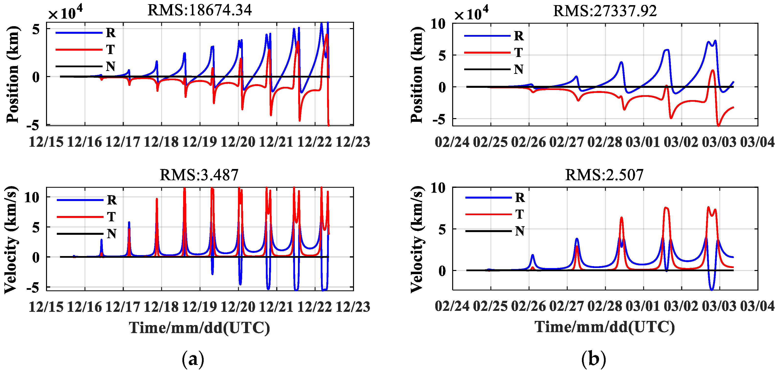
3.3. Accuracy Analysis of Thrust Orbit Determination for Transfer Orbit

The typical arcs with thrust in the transfer orbit of the all-electric-propulsion GEO satellite from 00:00:00 on 25 July 2019 to 00:00:00 on 26 July 2019 are selected, and the real orbit is determined by integration based on the initial orbit + electric thrust + other dynamics. Then, the GNSS pseudorange and phase data are generated by simulation using the noise level according to the indications of the GNSS receiver in Table 2 and the simulation strategy shown in Table 3. The orbit determination accuracy under thrust in the transfer section is analyzed.
Analysis of the observation data generated by the simulation shows that the highest satellite altitude is 53,721 km and the lowest is 5649 km. The GNSS data of the three integrated antennas are obtained, and the arcs with at least four GPS satellites are 02:16–06:17 and 20:45–24:00. The arcs with at least four BDS satellites are 02:13–12:11 and 21:43–24:00. The arcs with at least four GLONASS satellites are 02:02–04:46 and 21:17–23:44. The arcs with at least four GNSS satellites are 00:30–12:30, 14:30–14:47, and 20:23–24:00.
As shown in Figure 7, in the arcs below 8000 km, the visible GNSS number of antenna 1 is 0. From 8000 km to 20,000 km, the visible GNSS number of antenna 1 increases rapidly from 4 to 14, and the GDOP of antenna 1 gradually increases from 2 to 50 as the altitude increases. In arcs above 20,000 km, the visible GNSS number of antenna 1 rapidly decreases to 4 with the increase in altitude. In arcs within 8000 km, the visible GNSS number of antenna 2 is 0. From 8000 km to 20,000 km, the visible GNSS number of antenna 2 also increases rapidly from 4 to 50, and the GDOP of antenna 2 gradually increases from 1 to 8 as the altitude increases. In the 20,000 km–30,000 km arcs, the visible GNSS number of antenna 2 rapidly decreases to less than 10, and the GDOP decreases to 25 with the increase of altitude. In arcs above 30,000 km, the visible GNSS number of antenna 2 is 0. In arcs within 8000 km, the visible GNSS number of antenna 3 is stable at 14–34, and the GDOP is stable at around 2. In arcs above 8000 km, the visible GNSS number of antenna 3 is 0.
Simulation data of transfer orbit with thrust are used to analyze the orbit determination accuracy. The initial value is taken from the ephemeris on 25 July 2019, and the error of the solar pressure model is fixed at 10%, pseudorange noise is 10 m, phase noise is 0.03 m, and the measurement extraction interval is 5 min. The orbit determination and forecast accuracy are analyzed for 10 h by solving for and fixing the empirical force [61,62].
The observation data from 00:30–12:30 is used to determine the orbit and to solve for empirical force, the orbit determination accuracy is 712 m, with a maximum error of 300 km for the 10 h forecast accuracy. A set of empirical forces to be solved are fixed as a priori values, and the orbit determination is carried out using the observation data from 00:30–12:30. Orbit determination accuracy is 709 m, with a maximum error of 20 km for the 10 h forecast accuracy, as shown in Table 7.
Compared with the direct calculation of the empirical force during orbit determination, the fixed use of the solved empirical force for orbit determination has little effect on the orbit determination accuracy but can significantly improve the prediction accuracy.

4. Discussion

4.1. Influence Analysis of Electric Thrust

Electric thrust, like other perturbation forces (such as solar radiation pressure, N-body perturbation, and nonspherical gravitational perturbation), will impact the satellite’s orbit, and the cumulative impact increases over time. Thus, it needs to be considered when determining the orbit in order to avoid it affecting the orbit determination accuracy. If the electric thrust can be accurately modeled, it will not affect the POD accuracy. However, due to the influence of various errors, such as control and installation, there is a big difference between the actual force and the theoretical model, resulting in a systematic deviation of the thrust model to affect orbit accuracy.
In order to improve the prediction accuracy of satellites that use electric thrust, it is necessary to use on-orbit data to calibrate the electric thrust model and to use the calibrated parameters in the subsequent orbit determination to improve the orbit determination accuracy. The calibration method can be determined by adjusting the size of factors on orbital experiments to determine the optimal factors, or some parameters can be solved and compared with the prior parameter values. Calibration of the electric thrust model is coupled with orbit determination, which uses external data to fit the relevant parameters in the thrust model.
Two typical arcs of the transfer orbit of the all-electric GEO satellite are selected: the initial orbit is 00:00:00 on 15 December 2019 and 00:00:00 on 24 February 2020. First, the reference orbit is obtained by numerical integration, and then the electric thrust is added for integration. As shown in Figure 8, the influence of the electric thrust on orbit determination is as big as about 60,000 km, far exceeding other perturbations.

4.2. Simulation Analysis of Electric Thrust Calibration

Satellite self-positioning data are obtained by using pseudorange data with single point position (SPP), which is not affected by satellite dynamics model error, so it can be used for electric thrust calibration. Simulation data are used to analyze the calibration accuracy of the electric thrust model; the simulation process is as follows:
(1)
According to the initial orbit, electric thrust, and other dynamic models, the real orbit of many days is obtained, and the real acceleration time series of electric thrust is output at the same time.
(2)
Simulate the self-positioning data of the spaceborne GNSS receiver, add a certain random error (10/100 m) in each direction (XYZ in the Earth-fixed coordinate system), and set the data measurement extraction interval as 5 min;
(3)
Use the self-positioning data of a certain arc to determine the orbit and the electric thrust model parameters. The calculated electric thrust model parameters are compared with the real thrust values to evaluate the calibration accuracy of the electric thrust.
(4)
The attitude error in the evaluation is considered to be 0.1 degrees.
Selecting the typical arcs used in the previous section, the simulation accuracy of electric thrust calibration is analyzed using the self-positioning data of different accuracy and arc length, and the results are shown in Table 8.
The calibration results show that the satellite self-positioning data accuracy and data arc length are the main factors affecting the calibration accuracy. Under the condition of 100 m accuracy of satellite self-positioning data and the arc length of 40 h orbit determination, the calibration accuracy of the electric thrust is about 10−9 m/s2, and for the arc length of 16 h orbit determination, the calibration accuracy of the electric thrust is about 10−7 m/s2. If the accuracy of satellite self-positioning data can reach 10 m, the accuracy of electric thrust calibration can also be improved by about one order of magnitude, and the 40 h orbit prediction can reach 1 km in 14 days.

5. Conclusions

The prediction accuracy of the transfer orbit and mission orbit of the all-electric propulsion GEO satellite based on onboard GNSS is studied by simulating the GNSS information of an all-electric propulsion GEO satellite. The main factors affecting the prediction accuracy of GEO satellite orbit determination under the condition of no thrust are also analyzed. An electric propulsion calibration algorithm is designed to analyze the prediction accuracy of orbit determination under thrust. The calculation results show that, using onboard GNSS technology, the orbit determination accuracy of all-electric GEO satellites is better than 10 m, the orbit determination accuracy of transfer orbit is better than 10 m, and the 14-day forecast accuracy is better than 1 km, which can provide support for transfer and mission orbit controls. The satellite self-positioning data are used to calibrate the electric thrust during satellite self-positioning data to 10 m accuracy. Using the 40 h orbit determination arc length data, the absolute calibration accuracy of the electric thrust is about 10−10 m/s2 magnitude, and the 14-day orbit forecast predicted accuracy can reach 1 km.

Author Contributions

Conceptualization, H.W. and G.W.; methodology, Y.H.; software, Y.H.; validation, W.L.; formal analysis, W.L.; resources, H.W.; data curation, W.L.; writing—original draft preparation, W.L. and Y.H.; writing—review and editing, G.W.; funding acquisition, Y.H. All authors have read and agreed to the published version of the manuscript.

Funding

This research is supported by the National Natural Science Foundation of China (grant no. U1931119) and the Preresearch Project on Civil Aerospace Technologies funded by the China National Space Administration (grant no. D010105).

Data Availability Statement

The data sources are supported by Shanghai Astronomical Observatory, Chinese Academy of Sciences.

Acknowledgments

The authors thank the Innovation Academy for Microsatellites Chinese Academy of Sciences for the satellite data, and WHU for MGEX ephemeris product support. The authors also thank Jianfeng Cao from Beijing Aerospace Control and Command Center and Xinglong Zhao from the China Academy of Space Technology for orbit determination software support.

Conflicts of Interest

The authors declare no conflict of interest.

References

  1. Martinez-Sanchez, M.; Pollard, J. Spacecraft electric propulsion-an overview. J. Propuls. Power 1998, 14, 688–699. [Google Scholar] [CrossRef] [Green Version]
  2. Jahn, R.G. Physics of Electric Propulsion; Courier Corporation: Chelmsford, MA, USA, 2006. [Google Scholar]
  3. Goebel, D.; Katz, I. Fundamentals of Electric Propulsion: Ion and Hall Thrusters; John Wiley & Sons: Hoboken, NJ, USA, 2008. [Google Scholar]
  4. O’Reilly, D.; Herdrich, G.; Kavanagh, D. Electric propulsion methods for small satellites: A review. Aerospace 2021, 8, 22. [Google Scholar] [CrossRef]
  5. Duan, C.; Chen, L. Research and Inspiration of All-electric Propulsion Technology for GEO Satellites. Spacecr. Eng. 2013, 22, 99–104. [Google Scholar]
  6. Duchemin, O.; Caratge, A.; Cornu, N.; Sannino, J.M.; Lorand, A. Ariane 5-ME and electric propulsion: GEO insertion options. In Proceedings of the 47th AIAA/ASME/SAE/ASEE Joint Propulsion Conference & Exhibit, San Diego, CA, USA, 31 July–3 August 2011; p. 6084. [Google Scholar]
  7. Yu, D.; Qiao, L.; Jiang, W.; Liu, H. Development and prospect of electric propulsion technology in China. J. Propuls. Technol. 2020, 41, 1–11. [Google Scholar]
  8. Tang, Z.; Zhou, C.; Han, D.; Ma, X.; Chen, T. Study on high power all-electric propulsion system for spacecraft orbit transfer. J. Deep. Space Explor. 2018, 5, 367–373. [Google Scholar]
  9. Hu, Y.; Mao, W.; Li, D.; Wei, L.; Wei, Y. The hall propulsion technology oriented all-electric-propulsion satellites. Aerosp. Control Appl. 2017, 43, 73–78. [Google Scholar]
  10. Wei, B.; Sun, X.; Wang, X. The Review of All-Electric Propulsion Platform on Satellite. Vac. Cryog. 2016, 22, 301–305+310. [Google Scholar]
  11. Yang, D. Research on Key Technologies of Orbit Design and Control for All Electric Satellite; Nanjing University of Aeronautics and Astronautics: Nanjing, China, 2016. [Google Scholar]
  12. Hu, Z.; Wang, M.; Yuan, J. A review of the development of all-electric propulsion platform in the world. Spacecr. Environ. Eng. 2015, 32, 566–570. [Google Scholar]
  13. Zuo, K.; Wang, M.; Li, M.; Tang, H. Research overview of commercial satellite platform with all-electric propulsion system. J. Rocket. Propuls. 2015, 41, 13–20. [Google Scholar]
  14. Sun, X.; Zhang, T.; Wang, X.; Wang, L.; Liu, M. The Research of Electric Propulsion’s Application of Electric Propulsion Satellite Platform. Vac. Cryog. 2015, 21, 6–10. [Google Scholar]
  15. Nishi, K.; Ozawa, S.; Matunaga, S. Design and guidance for robust orbit raising trajectory of all-electric propulsion geostationary satellites. Trans. Jpn. Soc. Aeronaut. Space Sci. Aerosp. Technol. Jpn. 2021, 19, 553–561. [Google Scholar] [CrossRef]
  16. Jin, G.; Kang, L. Design of Hall Electric Propulsion System in “Tianhe” Core Module. Aerosp. China 2021, 8, 22–27. [Google Scholar]
  17. Chen, M.; Liu, X.; Zhou, H.; Chen, C.; Jia, H. Research and development of micro electric propulsion technology for micro/nano satellites. J. Solid Rocket. Technol. 2021, 44, 188–206. [Google Scholar]
  18. Yang, F.; Wang, C.; Hu, J.; Zhang, H.; Wu, C.; Zhang, X.; Geng, H.; Fu, D. Technical project of ion propulsion for satellites in super low Earth orbit. Chin. Space Sci. Technol. 2021, 41, 52–59. [Google Scholar]
  19. Wang, Z.; Zhang, T.; Peng, K. Design of Electric Propulsion System for Ground-month Single-ship Cargo Ship. Vac. Cryog. 2020, 26, 317–322. [Google Scholar]
  20. Wang, S.; Xiong, S. Research on transfer orbit based on electric propulsion satellite to halo orbit. Chin. J. Space Sci. 2019, 39, 489–493. [Google Scholar]
  21. Ren, Y.; Wang, X. Development of High-performances Electric Propulsion System and the Application on GEO Satellite Platforms. Vac. Cryog. 2018, 24, 60–65. [Google Scholar]
  22. Kuai, Z. Research on Station Keeping and Orbital Transfer of Geostationary Satellites by Impulse and Electric Propulsion; University of Science and Technology of China: Hefei, China, 2017. [Google Scholar]
  23. Tian, B.; Xue, D.; Huang, M. Orbit Transfer Strategies for GEO Satellites Using All-electric Propulsion. Spacecr. Eng. 2015, 24, 7–13. [Google Scholar]
  24. Li, S. The Research on the Application of Electrical Propulsion Technology in GEO Satellite Orbit Control; National University of Defense Technology: Changsha, China, 2015. [Google Scholar]
  25. Feuerborn, S.A.; Perkins, J.; Neary, D.A. Finding a way: Boeing’s all electric propulsion satellite. In Proceedings of the 49th AIAA/ASME/SAE/ASEE Joint Propulsion Conference, San Jose, CA, USA, 14–17 July 2013; p. 4126. [Google Scholar]
  26. Casaregola1, C. Electric Propulsion for Station Keeping and Electric Orbit Raising on Eutelsat Platforms. In Proceedings of the Japan International Electric Propulsion Conference, Kobe, Japan, 4–10 July 2015. [Google Scholar]
  27. Zhou, Z.; Gao, J. Development Approach to All-Electric Propulsion GEO Satellite Platform. Spacecr. Eng. 2015, 24, 1–6. [Google Scholar]
  28. Zhang, T. The LIPS-200 Ion Electric Propulsion System Development for the DFH-3B Satellite Platform. In Proceedings of the 64th International Astronautical Congress, Beijing, China, 23–27 September 2013. [Google Scholar]
  29. Zhang, T. Initial Flight Test Results of the LIPS-200 Electric Propulsion System on SJ-9A Satellite. In Proceedings of the International Electric Propulsion Conference, Washington, DC, USA, 6–10 October 2013. [Google Scholar]
  30. Zhang, T. New progress of electric propulsion technology in LIP. J. Rocket. Propuls. 2015, 41, 7–12. [Google Scholar]
  31. Wen, Z.; Shi, M.; Geng, H.; Zhang, W.; Li, Z. Application and Fight Testing of Ion Electric Propulsion in High Throughout Satellite. Vac. Cryog. 2022, 28, 79–86. [Google Scholar]
  32. Wang, H.; Li, G.; Shi, B.; Zhang, J.; Jiang, G.; Shen, Y.; Wu, G. Orbit Transfer Method of All-electric Propulsion SmallGEO Satellite Based on GNSS. Radio Commun. Technol. 2020, 46, 527–533. [Google Scholar]
  33. Hofmann-Wellenhof, B.; Lichtenegger, H.; Wasle, E. GNSS–Global Navigation Satellite Systems: GPS, GLONASS, Galileo, and More; Springer: Berlin, Germany, 2007. [Google Scholar]
  34. Groves, P. Principles of GNSS, inertial, and multisensor integrated navigation systems. IEEE Aerosp. Electron. Syst. Mag. 2015, 30, 26–27. [Google Scholar] [CrossRef]
  35. Li, X.; Ge, M.; Dai, X.; Ren, X.; Fritsche, M.; Wickert, J.; Schuh, H. Accuracy and reliability of multi-GNSS real-time precise positioning: GPS, GLONASS, BeiDou, and Galileo. J. Geod. 2015, 89, 607–635. [Google Scholar] [CrossRef]
  36. Zhou, X.; Wang, X.; Zhao, G.; Peng, H.; Wu, B. The precise orbit determination for hy2a satellite using GPS, DORIS and SLR data. Geomat. Inf. Sci. Wuhan Univ. 2015, 40, 1000. [Google Scholar]
  37. Gong, X.; Wang, F. Autonomous orbit determination of hy2a and zy3 missions using space-borne GPS measurements. Geomat. Inf. Sci. Wuhan Univ. 2017, 42, 309–313. [Google Scholar]
  38. Yuan, J.; Zhao, C.; Wu, Q. Phase center offset and phase center variation estimation in-flight for zy-3 01and zy-3 02spaceborne GPS antennas and the influence on precision orbit determination. Acta Geod. et Cartogr. Sin. 2018, 47, 672–682. [Google Scholar]
  39. Li, M.; Li, W.; Shi, C.; Jiang, K.; Guo, X.; Dai, X.; Meng, X.; Yang, Z.; Yang, G.; Liao, M. Precise orbit determination of the Fengyun-3C satellite using onboard GPS and BDS observations. J. Geod. 2017, 91, 1313–1327. [Google Scholar] [CrossRef] [Green Version]
  40. Li, W.; Li, M.; Zhao, Q.; Shi, C.; Guo, X.; Meng, X.; Yang, Z. FY3C Satellite Onboard BDS and GPS Data Quality Evaluation and Precise Orbit Determination. Acta Geod. et Cartogr. Sin. 2018, 47, 9–17. [Google Scholar]
  41. Zhao, X.; Zhou, S.; Ci, Y.; Hu, X.; Cao, J.; Chang, Z.; Tang, C.; Guo, D.; Guo, K.; Liao, M. High-precision orbit determination for a LEO nanosatellite using BDS-3. GPS Solut. 2020, 24, 102. [Google Scholar] [CrossRef]
  42. Powell, T.; Martzen, P.; Sedlacek, S.; Chao, C.-C.; Silva, R. GPS Signals in a Geosynchronous Transfer Orbit:“Falcon Gold” Data Processing. In Proceedings of the 1999 National Technical Meeting of the Institute of Navigation, San Diego, CA, USA, 25–27 January 1999; pp. 575–585. [Google Scholar]
  43. Bauer, F.; Moreau, M.; Davis, E.; Carpenter, J.; Kelbel, D.; Davis, G.; Axelrad, P. Results from the GPS flight experiment on the high earth orbit amsat oscar-40 spacecraft. In Proceedings of the 15th International Technical Meeting of the Satellite Division of the Institute of Navigation, Portland, OR, USA, 24–27 September 2002. [Google Scholar]
  44. Unwin, M.; Blunt, P.; de Vos van Steenwijk, R. Navigating above the GPS constellation—Preliminary results from the SGR-GEO on GIOVE-A. In Proceedings of the 26th International Technical Meeting of the Satellite Division of the Institute of Navigation, Nashville, TN, USA, 16–20 September 2013. [Google Scholar]
  45. Barker, L.; Frey, C. GPS at GEO: A first look at GPS from SBIRS GEO. Adv. Astronaut. Sci. 2012, 144, 199–212. [Google Scholar]
  46. Fan, M.; Hu, X.; Dong, G.; Huang, Y.; Cao, J.; Tang, C.; Li, P.; Shengqi, C.; Yu, Y. Orbit improvement for Chang’e-5T lunar returning probe with GNSS technique. Adv. Space Res. 2015, 56, 2473–2482. [Google Scholar] [CrossRef]
  47. Wang, M.; Shan, T.; Ma, L.; Tao, R.; Chen, C. Performance of GPS and GPS/SINS navigation in the CE-5T1 skip re-entry mission. GPS Solut. 2018, 22, 1–12. [Google Scholar] [CrossRef]
  48. Wang, M.; Shan, T.; Wang, D. Development of GNSS technology for high earth orbit spacecraft. Acta Geod. et Cartogr. Sin. 2020, 49, 1158–1167. [Google Scholar]
  49. Li, B.; Liu, L.; Wang, M. Performance demonstration and analysis of GNSS navigation in geo satellites. Aerosp. Shanghai 2017, 34, 133–143. [Google Scholar]
  50. Jiang, K.; Min, L.; Wang, M.; Zhao, Q.; Li, W. Tjs-2 geostationary satellite orbit determination using onboard GPS measurements. GPS Solut. 2018, 22, 1–14. [Google Scholar] [CrossRef]
  51. Zhu, J.; Wang, C.; He, Y.; Yang, Y. High Accuracy Navigation for Geostationary Satellite TTS-II via Space-borne GPS. In Proceedings of the 39th Chinese Control Conference, Shenyang, China, 27–30 July 2020; pp. 3362–3367. [Google Scholar]
  52. Winternitz, L.; Bamford, W.; Heckler, G. A GPS receiver for high-altitude satellite navigation. Selected Topics in Signal Processing. IEEE J. 2009, 3, 541–556. [Google Scholar]
  53. Han, M.; Wang, Y. Optimization method for orbit transfer of all-electric propulsion satellite based on reinforcement learning. Syst. Eng. Electron. 2022, 44, 1652–1661. [Google Scholar]
  54. Duan, C.; Ren, L.; Chang, Y.; Bai, Q.; An, R.; Huang, Y. All-electric propulsion satellite trajectory optimization by homotopic approach. Chin. Space Sci. Technol. 2020, 40, 42–48. [Google Scholar]
  55. Wang, M.; Li, Q.; Liang, X.; An, R. Low-Thrust Orbit Transfer Strategy On-Board Computation for All Electric Propulsion Satellite. J. Propuls. Technol. 2020, 41, 180–186. [Google Scholar]
  56. Cui, Z.; Zhou, L.; Hu, S.; Gong, J. An electric thrust vector calibrating algorithm using angular momentum. Chin. Space Sci. Technol. 2019, 39, 1–8. [Google Scholar]
  57. Li, H.; Topputo, F.; Baoyin, H. Autonomous time-optimal many-revolution orbit raising for electric propulsion geo satellites via neural networks. arXiv 2019, arXiv:1909.08768. [Google Scholar]
  58. Montenbruck, O.; Gill, E. Satellite Orbits; Springer: Berlin/Heidelberg, Germany, 2000. [Google Scholar]
  59. Wu, Z. Researches on Precise Orbit Determination Based GNSS and Its Application; University of Chinese Academy Sciences: Beijing, China, 2018. [Google Scholar]
  60. Fan, M. Researches of GNSS-Based Navigation for Lunar Missions; University of Chinese Academy Sciences: Beijing, China, 2017. [Google Scholar]
  61. Zhu, J.; Wang, J.; Chen, J.; He, Y. Centimeter precise orbit determination for HY-2 via DORIS. J. Astronaut. 2013, 34, 163–169. [Google Scholar]
  62. Montenbruck, O.; Helleputte, T.; Kroes, R.; Gill, E. Reduced Dynamic Orbit Determination using GPS Code and Carrier Measurements. Aerosp. Sci. Technol. 2005, 9, 261–271. [Google Scholar] [CrossRef]
Figure 1. Time-dependent graph of satellite height.
Remotesensing 14 02627 g001
Figure 2. Installation diagram of thruster and GNSS antennas.
Remotesensing 14 02627 g002
Figure 3. GNSS satellite geometry visible schematic.
Remotesensing 14 02627 g003
Figure 4. Visible GNSS number and GDOP of antenna 1. (a) Visible GNSS number of antenna 1. (b) GDOP of antenna 1.
Remotesensing 14 02627 g004
Figure 5. Orbit overlap difference using GPS broadcast ephemeris.
Remotesensing 14 02627 g005
Figure 6. Visible GNSS number and GDOPs of antennas 1, 2, and 3. (a) Visible GNSS number of antenna 1. (b) Visible GNSS number of antenna 2. (c) Visible GNSS number of antenna 3. (d) GDOP of antenna 1. (e) GDOP of antenna 2. (f) GDOP of antenna 3.
Remotesensing 14 02627 g006
Figure 7. Visible GNSS number and GDOP of antennas 1, 2, and 3 (a) Visible GNSS number of antenna 1. (b) Visible GNSS number of antenna 2. (c) Visible GNSS number of antenna 3. (d) GDOP of antenna 1. (e) GDOP of antenna 2. (f) GDOP of antenna 3.
Remotesensing 14 02627 g007
Figure 8. Electrical thrust effect. (a) Electrical thrust effect of phase 1. (b) Electrical thrust effect of phase 2.
Remotesensing 14 02627 g008
Table 1. GNSS receiver indicators.
TypeIndicators
Operating frequencyGPS L1/GLONASS L1/BDS B1
Time accuracy<5 us
Pseudo-Range Measurement Accuracy (RMS)<1 m (height < 1000 km),
<10 m (height < 36,000 km)
Carrier Phase Accuracy (RMS)<5 mm (height < 1000 km),
<3 cm (height < 36,000 km)
Measurement extraction interval 5 min
Table 2. GNSS satellites used in the simulation.
TypePRNNUM
GPSG01~G32 (except G04/G19)30
GLONASSR01~R24 (except R06/R12)22
BDSC01~C37 (except C15/C16/C17/C18/C20/C28/C30/C31)29
Table 3. GNSS observation data simulation strategy.
TypeValue
Arc length24 h
Measurement extraction interval5 min
Pseudorange noise (RMS)10 m
Phase noise (RMS)0.03 m
GNSS satellite ephemerisMGEX-WHU
GNSS satellite clock differenceMGEX-WHU
Earth gravity fieldEIGEN_GL04C (100 × 100)
N bodyDE421
Solid tideIERS 2003
Sea tideFES2004
Solar radiation pressureFixed surface-to-mass ratio model
Table 4. Processing strategy for POD.
ModelDescribe
Arc length24 h
Measurement extraction interval5 min
Pseudorange noise (RMS)10 m
Phase noise (RMS)0.03 m
Earth gravity fieldEIGEN_GL04C (100 × 100)
N bodyDE421
Solid tideIERS 2003
Sea tideFES2004
Solar radiation pressureFixed surface-to-mass ratio model
Estimated parametersSatellite initial state (position, velocity) receiver clock error, phase ambiguity
Observation data weightsThe weight ratio of code observation to phase observation is 1/100
GNSS navigation satellite ephemerisPrecision ephemeris
(add 0.1 m position error)
Table 5. POD accuracy with different model errors (RMS).
Model ErrorsPOD Accuracy (m)
Observation dataPseudorange noise (6 m)0.15
5 h arc length1.19
Pseudorange only 1.2
GNSS navigation satellite ephemerisGPS only0.27
Precision ephemeris
(add 1 m position error)
1.34
Dynamics modelEarth gravity field5 × 50.24
3 × 30.44
2 × 25.66
Solar radiation pressure5% error0.66
10% error1.32
Table 6. Orbit determination and prediction of different conditions.
Navigation SystemEphemerisArc LengthOrbit Determination Accuracy (m)14-Day Prediction Accuracy (m)
GNSS
(GPS + BDS + GLONASS)
Final precision ephemeris
(0.1 m error)
24 h continuous1.56272.29
24 h discontinuity1.94628.6
10 h0.97552.75
5 h1.4858.84
Broadcast ephemeris24 h continuous5.03396.87
24 h discontinuity6.19928.49
10 h5.021213.25
5 h5.433147.11
GPSFinal precision ephemeris (0.1 m error)24 h continuous1.89411.81
24 h discontinuity1561.61
10 h0.59667.52
5 h0.85743.44
Broadcast ephemeris24 h continuous4.86477.74
24 h discontinuity4.61685.85
10 h4.351369.57
5 h5.232061.98
BDSFinal precision ephemeris
(0.1 m error)
24 h continuous1.94253.21
24 h discontinuity2.96469.1
10 h1.37834.45
5 h1.96997.81
Broadcast ephemeris24 h continuous5.3303.39
24 h discontinuity5.92747.34
10 h7.07692.47
5 h5.232521.03
Table 7. Analysis of orbit determination and prediction accuracy.
Empirical Force Processing StrategyOrbit Determination Accuracy (m)10 h Prediction Accuracy (km)
Solve712300
Fix after solving70920
Table 8. Analysis of 14-day prediction and calibration accuracy.
Self-Positioning Data Error (m)Arc Length (hours)14-Day Prediction Accuracy (km)Calibration Accuracy (m/s2)
1016201.2 d−08
104011.9 d−10
100162001.2 d−07
1004041.9 d−9
Publisher’s Note: MDPI stays neutral with regard to jurisdictional claims in published maps and institutional affiliations.

