1. Introduction
In recent years, research in the space community has shown a growing interest in the application of Artificial Intelligence (AI), and in particular Deep Learning (DL), on board spacecrafts in view of its potential advantages [
1,
2,
3,
4,
5]. One main reason is due to the high potential demonstrated by Deep Neural Network (DNN) models for many different space applications, such as object-detection [
3] and recognition, image scene classification [
6,
7], super-resolution [
8], agricultural-crop detection [
9], and change detection [
10], outperforming classical approaches both in terms of performance and time to design. Thanks to this capability, DNNs might be applied on board Earth Observation (EO) satellites for applications such as fire detection or oil-spill detection, requiring the minimization of processing and transmission latency and the impact of the consequent damages [
2].
The deployment of DNNs on board spacecraft might also mitigate the problem of the increasing number of sensor data that must be downloaded to ground [
1,
5,
11]. Indeed, less usable data, like cloud-covered images, can be identified, tagged, pre-filtered, discarded, or selectively compressed [
2,
3]. In this regard, the use of aboard DNNs might extend the acquisition of images in areas of the planet such as deserts or oceans (which are usually scanned at lower priority to save bandwidth), enabling the detection of specific targets (e.g., detection of assets, vessels or random/sparse events as oil leaks).
One of the main research open points involves the choice of hardware accelerators for DNNs, which are computationally intensive and memory-hungry algorithms [
3,
12,
13]. Their deployment on board spacecrafts requires finding acceptable design trade-offs for the reduced power and memory budget of SmallSats like CubeSat [
2], where power generation and heat dissipation are stringent design issues.
The first DNN implementations have been software-based, involving Graphics Processing Units (GPUs), or Central Processing Units (CPUs). The high consumption of these devices is a problem even for data centers, meaning that their employment on board would be feasible for very small networks only (e.g., single input networks for sensor failure detection [
14]). The broad use of DNNs for commercial applications led to the realization of Commercial Off-The-Shelf (COTS) hardware accelerators for these algorithms, such as Myriad 2 Visual Processing Unit (VPU) [
15], Coral Tensor Processing Unit (TPU) Dev Board [
16], and Nvidia Jetson Nano GPU [
17]. These devices feature high energy efficiency and remarkable performance, cost, and mass trade-offs [
4]. Furthermore, they exploit open-source tools that highly speed up the deployment of the model, reducing the development time and costs with an acceptable level of reliability due to the wide diffusion in various fields (automotive, health, etc.), and the large open developer community. Owing to this, and thanks to their reconfigurability, the use of COTS hardware accelerators might lead to a significant reduction of mission costs and design in the future [
4].
Currently, however, the usability of COTS in space is limited because none of them is fully suitable to the space environment, mainly due to radiation tolerance concerns [
2,
18]. In particular, Single Event Effects (SEEs) are caused by charged particles impacting electronic devices, leading to soft errors such as Single Event Upsets (SEUs) and Single Event Transients (SETs) or permanent damages in the case of Single Event Latch-ups (SELs). Furthermore, a limited Total Ionizing Dose (TID) figure bounds devices’ reliability in space for long-term missions, confining their use for short-term Low Earth Orbit (LEO) applications. For Geostationary Earth Orbit (GEO) and Medium Earth Orbit (MEO) or long-lasting LEO missions, space-qualified devices are generally preferred because of their high reliability and long-term traceability and support [
18].
Space-qualified devices generally lag behind compared to their terrestrial counterparts because of their longer lifespan, older technology nodes, and their design typically more oriented to high dependability than performances. Because of this, space-qualified devices generally feature far worse performance/mass/cost trade-offs compared to other COTS [
2,
18].
In this scenario, Field Programmable Gate Arrays (FPGAs) are a good alternative for the acceleration of Neural Networks for on-the-edge space applications. FPGAs have always been used for prototyping purposes in any new digital technology. In the defense and space industry, they have been increasingly used in place of traditional Application Specific Integrated Circuits (ASICs) due to the low number of manufactured units for electronic equipment and faster Time to Market, remaining competitive in terms of performance with respect to alternative solutions [
18].
FPGAs are promising given their high portability, which permits the same design to be exploited for devices having different performance/radiation resistance trade-offs. An additional benefit is the flexibility in their configuration, which can be exploited in applications involving DL. For example, networks can be re-trained and improved during a mission, or multiple networks can be employed and adapted to customer needs.
Neural Networks for FPGAs have been typically complex to implement due to the high degree of manual optimization required to fully implement the network in programmable logic. Current developments in Design Tools from FPGA vendors, coupled with the advent of Systems-on-a-Chip (SoCs) that combine the power of multicore-processing with hardware accelerators, have enabled users to infer DNNs on FPGAs suitable for space (e.g., RTG4 [
19], Kintex XQRKU060 [
20]).
In this work, we present an FPGA-based hardware accelerator for the CloudScout Deep Neural Network [
3]. This network was developed in the framework of the CloudScout project [
21], led by the Dutch company Cosine Measurement systems [
22] and funded by the European Space Agency (ESA). The aim of this project was to realize a Convolutional Neural Network (CNN) for on board cloud detection of satellite hyperspectral images. In this way, cloud-covered images can be discarded to relax downlink bandwidth requirements.
On the satellite, the inference of the CNN is accelerated by the Myriad 2 VPU [
15], a COTS device that demonstrated high performance, low power consumption, and an acceptable resistance to radiation despite its COTS nature, which makes it usable for non-mission-critical applications [
15].
The proposed FPGA-based accelerator (devised in the framework of the TETRAMAX H2020 European project [
23]) is characterized through a custom benchmark. Resulting metrics are compared with the ones of the flying Myriad 2 solution. Despite the specific case study, this comparison aims to be extendable to generic space applications. The main contributions of this article are summarized below:
Realization of a portable FPGA-based accelerator, enabling the use of DNNs for missions having different requirements;
Custom scheduling and storage techniques for efficient use of the on-chip resources;
Innovative computations scheduling for timing and power performance improvement (zero-latency max pooling operations);
Benchmark between FPGA-based and COTS-based solutions for space applications.
The remainder of the article is structured as follows.
Section 2 consists of a brief survey of the use of FPGA devices to accelerate CNN algorithms. In
Section 3, an overview of the CloudScout CNN model is given.
Section 4 describes the proposed hardware architecture, while its implementation and characterization on a Zynq Ultrascale+ ZCU106 Evaluation Platform [
24] are presented in
Section 5. Implementation results for a Xilinx Kintex Ultrascale XQRKU060 are presented as well. Finally, in
Section 6, the benchmark between the VPU-based and FPGA-based solutions is given, with conclusions drawn in
Section 7.
3. The CloudScout Case Study
The CloudScout project targets the development of the very first CNN-based algorithm to fly on board a satellite [
21]. The CNN is exploited to perform cloud-detection by processing the hyperspectral images produced by the novel HyperScout-2 sensor on board the Phisat-1 6U CubeSat launched in September 2020 [
38,
39]. The algorithm classifies cloud-covered images and clear ones intending to discard unusable data and, thus, reduce the downlink bandwidth of the satellite [
3]. At the current state of the project, the inference is computed by the Myriad 2 VPU [
15], but this work aims to present an FPGA-based solution that can overcome some of the drawbacks linked to other COTS devices.
In this section, the original CloudScout CNN model is first described. Second, we give a brief description of the quantization process applied to shrink model complexity before the accelerator design.
The CloudScout model is a binary classifier that takes
images as input and classifies them as “cloudy” if more than 70% of the image surface is covered by clouds. The model was developed using an iterative method in the Keras Python [
40] environment and then trained by using a dataset of 21,546 hyperspectral images synthesized by Sinergise Ltd, Ljubljana, Slovenia [
41] starting from Sentinel-2 images [
3]. The achieved accuracy for the model is 92.3% on a test dataset composed of 10,766 images.
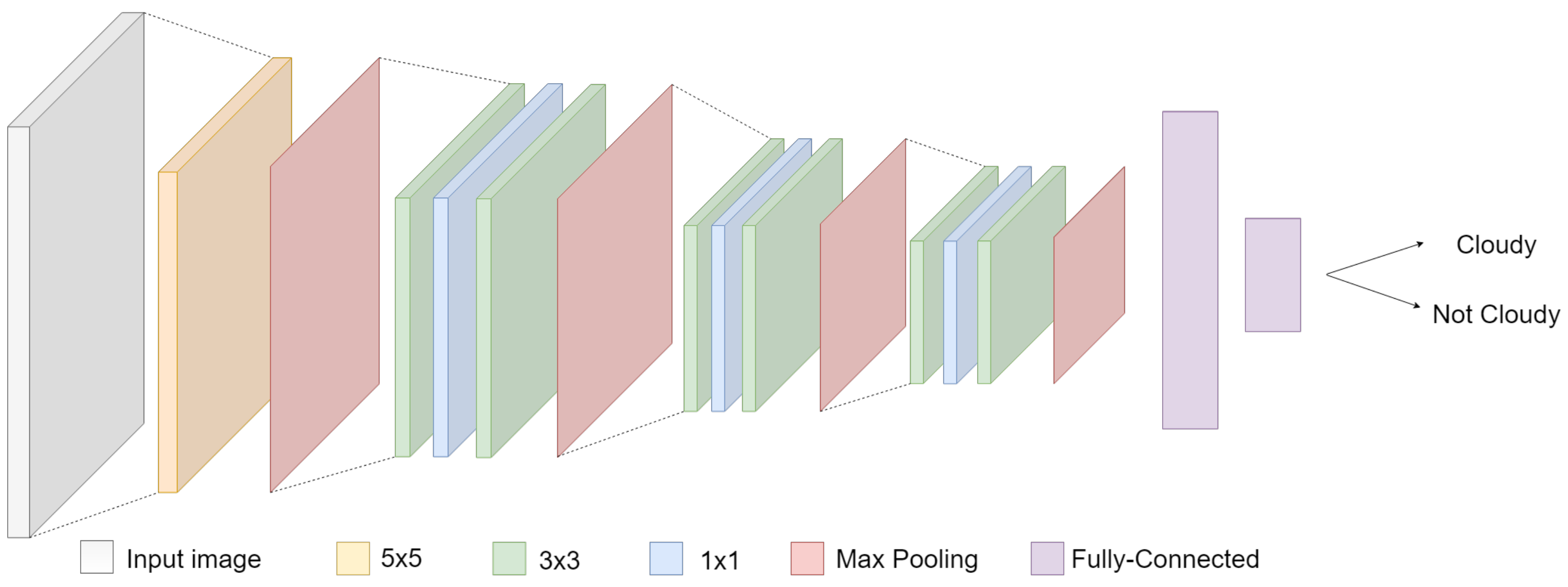
Figure 1 shows the model structure.
The Feature Extraction level is composed of ten convolutional layers, characterized by the absence of bias and squared filters. The first layer is characterized by a 5 × 5 kernel with a 2 × 2 max-pooling. It is then followed by three triplets of convolutional layers: each triplet exploits a sequence of kernels of 3 × 3, 1 × 1, 3 × 3, and finally applies 2 × 2 max pooling. The following Decision level consists of a cascade of two Fully Connected (FC) layers, used to provide the final binary output: cloudy/not-cloudy.
For more details about the CloudScout CNN model, please refer to [
3].
The CloudScout model was originally quantized through the NCSKD tool [
42] applying 16-bits floating-point representation, which is the only one allowed by the Myriad 2. The hyper-parameters used for training can be found in [
3].
For what concerns the FPGA-based accelerator, the network was further quantized to reduce the model complexity before proceeding to the hardware accelerator design. This process was necessary since the CloudScout model’s total memory footprint (204 Mbit) far exceeds the available storage resources on most commercial FPGA devices.
More specifically, we applied a customized backpropagation algorithm that runs during the training phase of the model, reduces the memory footprint by minimizing the representation bits, and optimizes computational resource exploitation by using a fixed point representation. This was achieved by properly tuning the loss function used in [
3] by adding a contribution depending on the representation and truncation bits of the network to be minimized. The quantized model was trained by using the RMSprop optimizer with learning rate 0.001 and early-stopping to avoid over-fitting. In particular, we used batch size 32 on the training set and batch size 8 on the validation set.
The performed quantization provided the following set of values for each layer:
The truncation bits and filter bits are a direct result of the quantization algorithm, while the saturation bits derive from a process of fine-tuning that considers the maximum values at all the points of the network for the entire dataset.
The obtained results are summarized in
Table 1.
As a result, our quantization process allowed shrinking the total memory footprint from 204 Mbit to 107 Mb (48% reduction), with a negligible accuracy drop of 0.3%.
4. Our FPGA-Based Hardware Accelerator
This section presents in detail our FPGA-based hardware accelerator, whose block scheme is shown in
Figure 2. In first place, we give an overview of the design.
Despite the quantization applied, the memory footprint of the network (approximately 107 Mbit) is larger than the available on-chip memory for most commercial FPGAs. For this reason, an external Double Data Rate (DDR) Synchronous Dynamic Random Access Memory (SDRAM) was integrated into the design to store the whole feature maps produced by convolutional layers during inference, as described for the Single Processing Unit architecture in
Section 2. The accelerator and the DDR memory communicate through an Advanced eXtendible Interface (AXI) bus [
43].
The elaboration of the input image is performed layer by layer sequentially. Due to memory constraints, only a few rows of the currently executed feature map are stored at a time in the on-chip Custom Cache. The latter is a memory block capable of pre-loading new data tiles from the external memory while the current set of rows is being processed, thus reducing computational stops due to off-chip data transfers. The Shared Convolutional Layer (SCL) is the processing engine, a flexible computational unit that can be tuned on the basis of specific layer parameters to efficiently exploit the implemented hardware resources. Filters are fully stored on the on-chip Filter memory using a custom order that optimizes the memory footprint. Max Pooling layers have been designed as a pipeline stage cascaded to the SCL block. This makes their impact negligible on the total inference time and on the required hardware resources. The outputs are then assembled by the Output Bridge to fully exploit the AXI bus capability. After the computation of the last convolution, FC layers directly compute the final output of the accelerator.
In the following subsections, more details about the main implemented blocks are given, putting the focus on the trade-off choices and the optimizations applied. The conventions used for convolutional operations are listed below:
: height of the q-th input feature map;
: width of the q-th input feature map;
: number of input channels for the q-th layer;
: number of output channels for the q-th layer;
: q-th layer filter size on both dimensions, considering the presence of square-shaped filters only;
: q-th layer pooling grid size on both dimensions, considering the presence of square-shaped grids only.
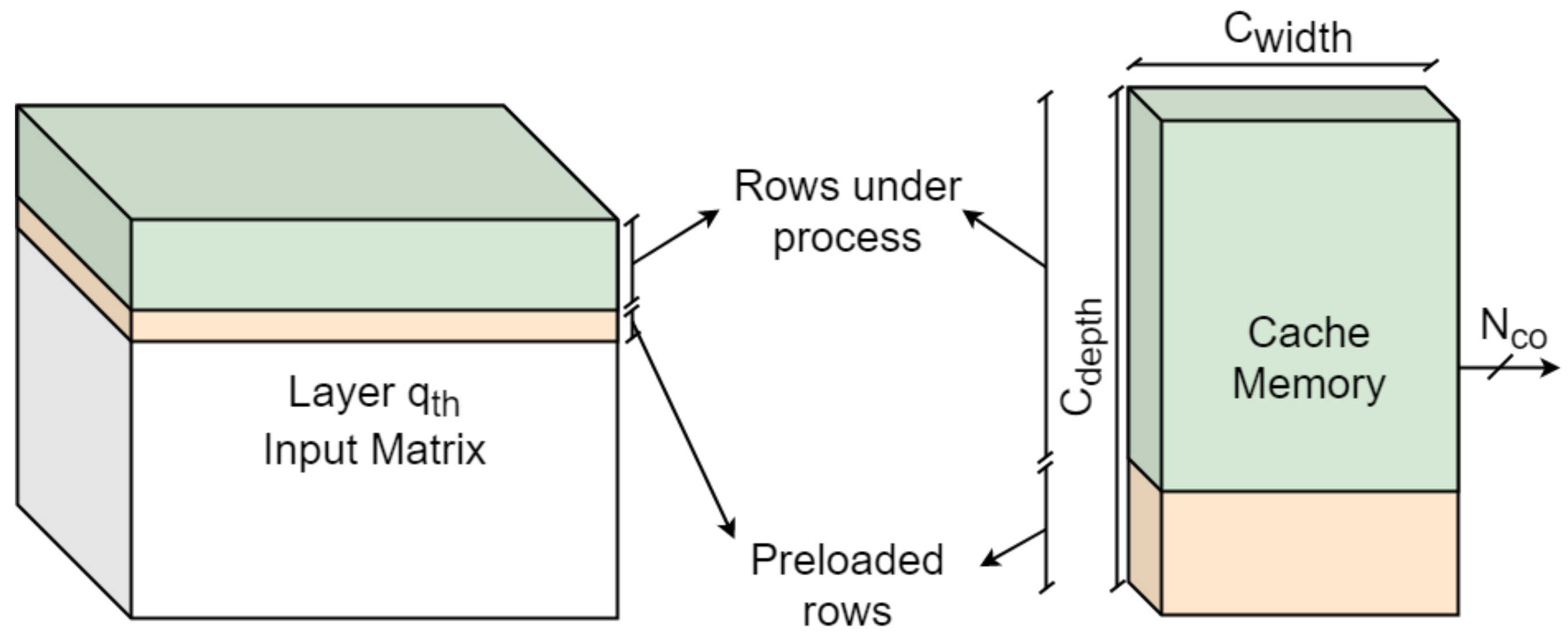
4.1. Custom Cache
The Custom Cache is the block responsible for storing tiles of the feature maps, which are entirely saved on the external memory. In particular, only a few rows of the currently computed feature map are loaded from the external memory into the cache through the AXI bus.
The logic inside the Custom Cache block handles writing operations so that the cache is continuously loaded with a new row as soon as the oldest ones have been completely exploited.
The cache can be filled even while the accelerator is performing computations. In this way, the accelerator needs to stop only when the AXI did not load enough elements for the convolution to continue.
The cache is characterized by three parameters:
,
,
. The word length
matches the length of the AXI bus packets. The memory depth
is given by evaluating the minimum storage resources needed by each layer to start computing. The worst case among layers is, thus, selected. Once
is fixed, the number of words read in parallel per clock cycle,
, should be sized not to exceed the available FPGA on-chip memory resources. Indeed, the memory footprint can be approximately estimated as
Figure 3 shows a simple scheme explaining the cache loading strategy.
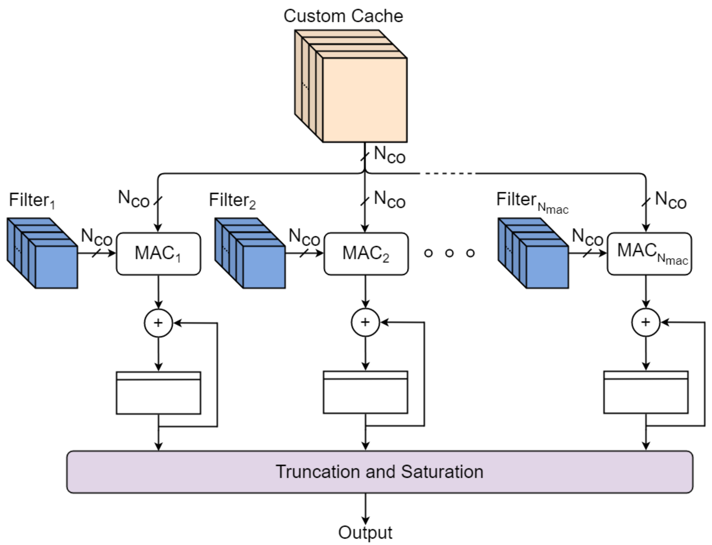
4.2. Shared Convolutional Layer
The SCL is the processing unit shown in
Figure 4. It is composed of a collection of
Multiply and Accumulate (MAC) blocks that perform product and sum operations between input elements extracted from the Custom Cache and filters provided by the Filter Memory. At every iteration, all MACs are fed with the same
input elements belonging to one input channel, but each MAC elaborates filters of different output channels. Once a channel-in swipe has been completed,
output elements of different output channels are ready. Increasing
value enhances the level of parallelism of the accelerator, speeding up the inference time at the cost of more hardware resources exploited.
After computing an output element, the accelerator shifts the filter position and proceeds to the next channel-in swipe, elaborating columns first and then rows. This scheduling algorithm is the best in terms of memory occupation as illustrated in [
28]. Every computed output is finally processed to perform truncation and saturation as specified in
Table 1.
The time needed to complete a channel-in swipe depends on the parameter, which is smaller than (i.e., number of elements for a complete channel-in swipe) due to the memory constraints mentioned above.
Apart from the standard operating mode, proper scheduling of MAC operations has been implemented to handle the following cases:
: once the first channel-in swipe ends, only elements are ready. Thus, before shifting the filter position for the next column, additional channel-in swipes should be computed to elaborate all the output channels;
: more than one clock cycle should be spent to read the necessary input elements belonging to the same input channel;
: in the case of 1x1 filters, every MAC can boost operation by elaborating parallel channel-in in one clock cycle (). This optimization results in a performance speedup.
Equation (
3) shows how to calculate the amount of needed clock cycles to complete the convolution within a specific layer.
The total number of clock cycles spent by the accelerator on performing convolutional operations is then:
4.3. Filter Memory
The Filter Memory has the task of storing the convolutional filters. All the filters are stored exploiting on-chip resources, and they do not have to be loaded from the external memory. Every single MAC is fed with a distinct memory that contains the filters needed by that unit only.
Every clock cycle, elements from all the memories should be read to guarantee correct MAC functionality. The word length, , can be chosen to save the entire elements as long as the filters’ quantization bits allow it.
Figure 5 shows how
has been designed for 5 × 5, 3 × 3, and 1 × 1 filters in order to minimize the memory footprint for our network and make all filters fit the FPGA available resources.
The depth of each memory,
, is chosen to be high enough so that it can contain all the elements required to perform all convolutions assigned to a specific MAC. The memory footprint of the filter memory can be calculated as in Equation (
5):
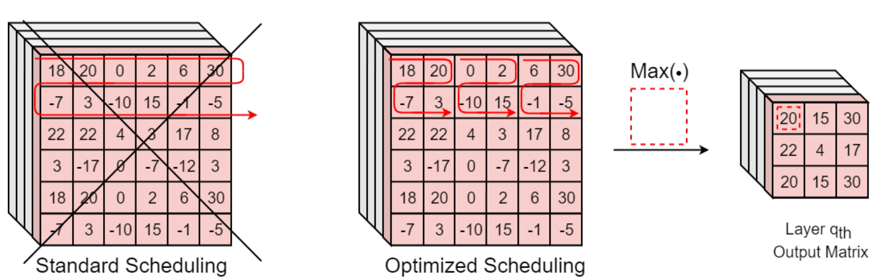
4.4. Max Pooling
The Max Pooling block performs max pooling and global max pooling operations whenever they are needed. This unit elaborates the SCL results in the pipeline in order to minimize elaboration time. A proper SCL output generation scheduling has been designed to achieve this purpose. In particular, if max pooling should be performed on
grids, the SCL outputs are generated according to the grid order rather than making iterations along all elements from the same row. In this way, the Max Pooling block directly provides the maximum value among the consequent
elements received, with no need to wait for the SCL to elaborate and store
input elements. This optimization provides better performance and power consumption at the cost of little logic, when compared to other solutions in the literature, such as [
44], where pooling operations are applied to the entire input layer only once all the elements are computed.
Figure 6 reports an example for the study case
.
5. Implementation Results and Experimental Measurement
The design proposed in
Section 4 is based on a versatile VHDL code that makes the accelerator configurable to fit different target FPGAs or to meet different design constraints. Indeed, it is possible to configure the accelerator parameters (
,
,
,
,
) in order to act on the exploited hardware resources and find a good trade-off between timing and power performance.
In our case study, we chose the configuration in
Table 2 with the purpose to minimize the inference time, at the cost of hardware resources and power consumption.
The hardware accelerator was first integrated within the system in
Figure 7 (described in
Section 5.1) and implemented on a Zynq Ultrascale+ ZCU106 Development Board, hosting a XCZU7EV-2ffvc1156 FPGA. Second, the only accelerator was implemented on a rad-hard Xilinx Kintex Ultrascale XQRKU060, which is functionally and electrically equivalent to the next generation of Xilinx space-qualified devices [
20]. The implementation results for this device are presented in
Section 5.2.
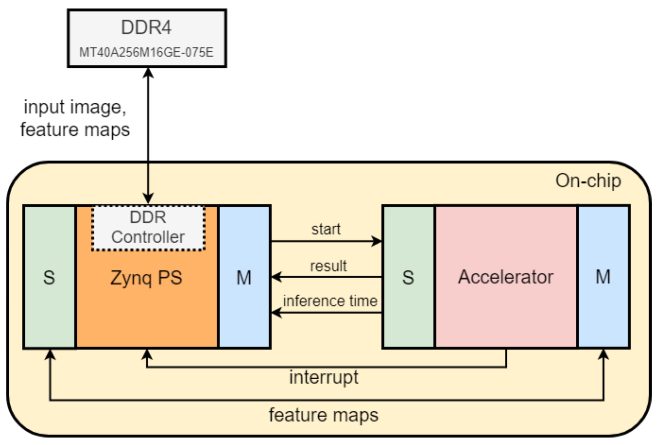
5.1. Zynq Ultrascale + ZCU106 System
The system shown in
Figure 7 was used to evaluate accelerator performance in terms of inference time and power consumption.
The Multiple Processor System-on-Chip (MPSoC) of the Zynq Ultrascale+ family consists of two parts: Programmable Logic (PL) and Processing System (PS). The PS is used to control the CloudScout accelerator implemented on the hardware resources of the PL. More specifically, the PS includes a 64-bit quad-core Arm Cortex-A53, which runs a C code to load the input images to the Micron MT40A256M16GE-075E DDR4 memory hosted on the board. After this operation, the CPU generates a start signal, so that the accelerator can begin with convolutional computations. At the end of the inference, the accelerator generates an interrupt signal for the processor. When the latter is acknowledged by the PS, the software application shows by Universal Asynchronous Receiver-Transmitter (UART) serial terminal the result of the inference and the measured value for the inference time.
The PS and the accelerator communicate via an AXI bus. The PS Master—Accelerator Slave interface is used to control the state of the accelerator. The Accelerator Master—PS Slave interface is used to transfer data from the accelerator to the external DDR memory, exploiting the controller integrated into the PS. The accelerator AXI Master is equipped with asynchronous First-In-First-Out (FIFO) memories so that the bus operating clock frequency can differ from the accelerator’s one, allowing a reduction of off-chip data transfer overhead times. The maximum clock frequency for the accelerator and the AXI bus are
= 115.4 MHz,
= 200 MHz, respectively. Multiple inferences were correctly executed using the described system.
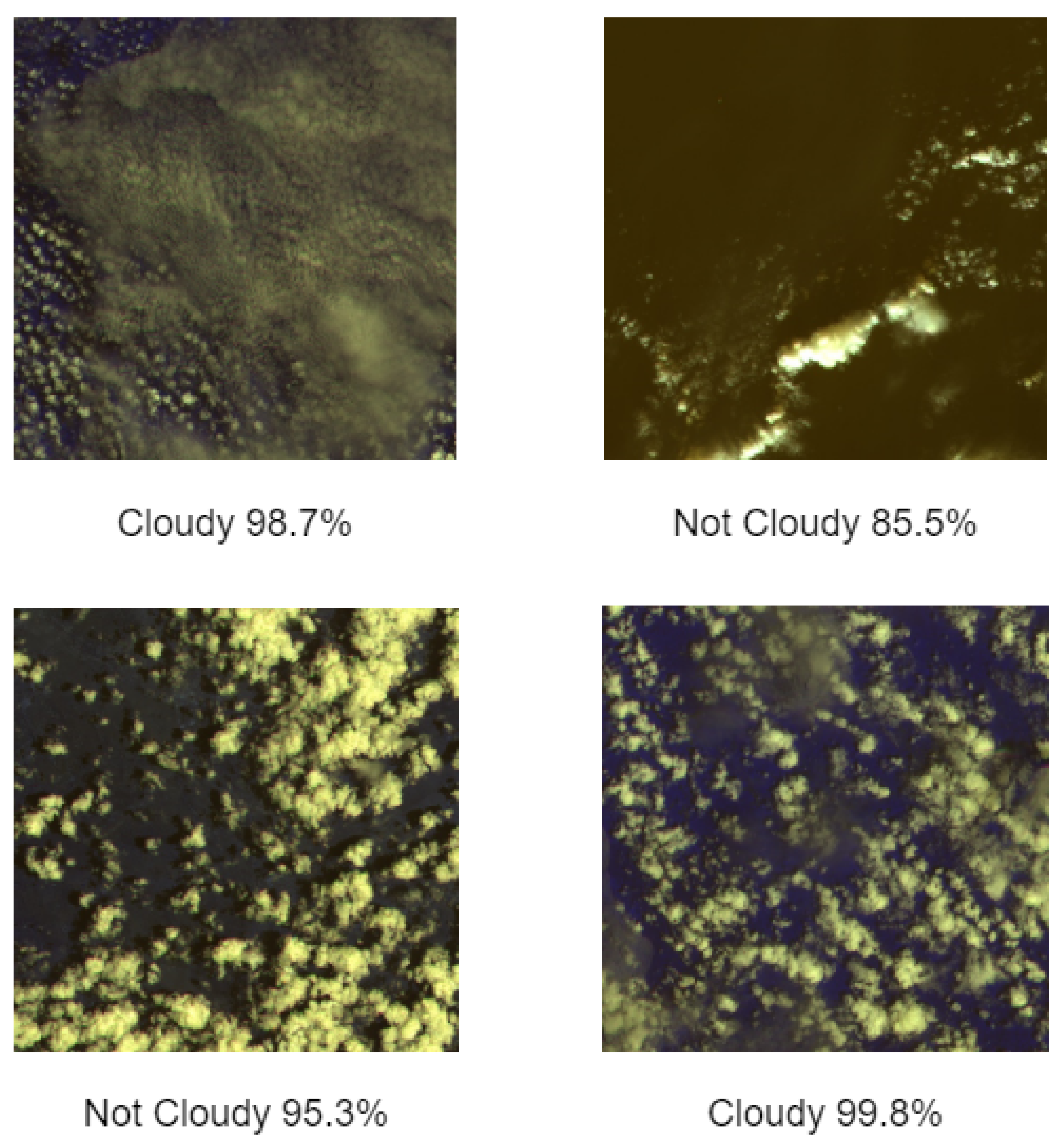
Figure 8 shows some examples of processed images and respective inference results in terms of a confidence score. The procedures to calculate the confidence score and pre-process data are described in [
3]. It is important to remember that a certain image is considered “cloudy” only if at least 70% of its pixels are covered by clouds.
The inference time was measured using an internal counter that is triggered by the start signal (generated by the CPU) and stopped at the end of the inference. The average value obtained was ms.
The inference time estimated by applying Equation (
4) was
ms. The variation of
ms between the two results can be assigned to the overhead introduced by the AXI interface used in the testing system. Power measures were done applying methods described in [
24,
46]: data were collected through the INA226 power monitors hosted on the ZCU106 for the various power rails via software and compared with current measures logged during inference via the Digital PowerTool software from Maxim Integrated.
The average power consumption of = 3.4 W was measured for the entire system and with the specified clock frequencies. The average power consumption measured for the only accelerator (PL side of the target FPGA) consists in = 1.65 W.
These values can be compared with the estimations obtained from the Xilinx Power Estimator (XPE) tool (with default settings), which gives 5.33 W for the entire system and 2.53 W for the accelerator only. The comparison shows that the XPE estimation is oversized, with a variation of and , respectively.
Table 3 summarizes the obtained characterizing parameters, with the addition of
being the energy spent per inference.
For what concerns hardware resources,
Table 4 shows implementation results for the XCZU7EV FPGA.
UltraRAM blocks are exploited for the realization of the Custom Cache, while BlockRAMs are used to store the filters of the network and to implement the AXI FIFOs. Most DSPs are deployed for implementing MAC modules in the SCL and in the Fully-Connected layers. In particular, each DSP corresponds to a multiplier [
13] (e.g.,
DSPs used for each MAC in the SCL).
5.2. Kintex Ultrascale KU060 Implementation
The accelerator presented in
Section 4 can be seen as a first step toward the design of a space-qualified hardware accelerator for rad-hard FPGAs. As an example, we also implemented our design on a Kintex Ultrascale XQRKU060 FPGA [
20], which represents the next generation of Xilinx space-qualified devices.
The maximum clock frequencies for this implementation were
= 52.08 MHz,
= 161.3 MHz. The inference time was estimated through Equation (
4) and equal to
= 264.72 ms. The XQRKU060 has worse timing performance with respect to the design implemented on the ZCU106 board because it belongs to an older FPGA family (Ultrascale vs. UltraScale+). For the Kintex implementation, power consumption was estimated through the XPE tool and equal to
= 1.6 W. It must be noted that this value is only the power consumed by the accelerator. In other words, this does not consider the power consumed by the DDR memory or by an eventual CPU for system control.
Table 5 summarizes the obtained characterizing parameters. As previously mentioned, the inference time and power consumption are estimations given by the design tools.
Table 6 shows the summary for the exploited hardware resources on this device.
6. Benchmark: FPGA and Myriad2
This section aims to offer a portrait of the advantages and disadvantages of using a COTS embedded solution or an FPGA-based solution for the acceleration of AI on board satellites, focusing on available technology and design techniques. FPGAs and Myriad 2 are compared with regard to the following metrics:
Technology radiation tolerance, which is the capability of a device to be immune to the effects of the space radiation environment;
Space-oriented Design, meant as the application of specific architectures, techniques or communication protocols to enforce the system radiation tolerance;
Costs of the devices;
Design flexibility, which refers to the possibility of implementing different features and algorithms on a target device or the possibility of implementing the design on different devices;
Developing time, which is the time necessary to develop a ready-to-fly system;
Inference time, which is the time that elapses between when input data are provided and when the final output is produced;
Power consumption, a significant parameter for on the edge systems because their available power budget is usually limited.
6.1. Space-Oriented Technology
High reliability is a key factor in the selection of components for space applications since the harsh nature of the space environment is a cause of possible hazards and system failures.
Current technology trends for COTS devices, such as increased clock frequencies, reduced feature sizes, and reduced supply and threshold voltages, harm the fault tolerance of the circuit. Due to the constant shrink in the transistor dimensions, faults that once were considered negligible are now significant enough to cause upsets that can perturb the integrated circuit operation [
47,
48].
In this scenario, rad-hard FPGAs constitute a valid candidate since they manage to combine high performance with enhanced radiation tolerance [
2,
18,
48].
To better understand the benefits of a space-qualified FPGA,
Table 7 reports the TID and SEL immunity values for some rad-hard FPGAs including RTG4 [
19], BRAVE Large [
49] and Kintex XQRKU060 [
20]. Results of the de-risking radiation test campaign carried out at CERN on the Myriad-2 VPU are also given [
2].
The European Cooperation for Space Standardization (ECSS) indicates that a device can be considered SEL-immune if it does not show any effect for a Linear Energy Transfer (LET) up to 60 MeV · cm
mg
[
50]. Thus, all the FPGAs indicated in
Table 7 can be considered SEL-immune, differently from Myriad 2 [
51,
52]. Rad-hard FPGAs also support a TID two to three times greater. This does not constitute an advantage for LEO missions since the typical TID per year in these orbits is in the range of the Krad [
53], and EO missions can last from 1 to 2 years for small satellites like CubeSat and up to 7 years for higher-profile satellites such as Sentinel-2 [
54]).
6.2. Space-Oriented Design
FPGAs allow developing electronic designs completely oriented towards space applications. Apart from technology, FPGAs feature the advantage of a customizable design, which can be equipped with redundant structures to enhance reliability and robustness by design. For example, Error Detection And Correction (EDAC) techniques can be exploited to secure the transmission of data from/to RAM memories [
55], and Triple Modular Redundancy (TMR) can mitigate SEU effects for combinational logic [
56].
Another advantage about FPGAs’ flexibility concerns quantization. Indeed, the possibility of minimizing the number of representation bits for data within the model helps to reduce the design area when compared to solutions like the Myriad 2, where there is no degree of choice. This is an advantage because the SEU probability is proportional to the area of the implemented circuit and because unused resources on the FPGA can be exploited for redundancy, as previously discussed.
Thanks to FPGA programmable logic, it is also possible to interface hardware accelerators with space-design communication protocols, according to design requirements, such as the well-established SpaceWire [
57] or the newest high-speed interfaces SpaceFibre [
58,
59], RapidIO [
60], and TTEthernet [
61]. These standards implement Fault Detection Isolation and Recovery (FDIR) mechanisms to identify and re-send data packets corrupted by incident radiation during the transmission process, without any data loss. Furthermore, SpFi and RapidIO support multi-lane links, which means that each communication link is composed of several lanes working in parallel. The multi-lane feature makes the communication system intrinsically redundant, increasing system robustness and reliability: in case of one or more lane failures, the system can continue to transmit and receive data.
The Myriad 2 communicates with the Hyperscout-2 back-end electronics through an Ethernet communication interface [
39], which does not implement any of the mentioned techniques to mitigate SEU effects [
56] and thus is not ideal for the space environment. Moreover, the Myriad2 requires exploiting the OpenVino [
62] or the previous NCSDK [
42] environments to be programmed. These Application Program Interfaces (APIs) are based on Windows, Linux, or other Operative Systems, which are not optimal for space applications. Operative Systems such as Real-Time Executive for Multiprocessor Systems (RTEMS) [
63] are generally preferred since they are verified to operate in space.
6.3. Costs, Design Flexibility, and Developing Time
Rad-hard devices are designed to properly work in the harsh space environment and have to respect strict requirements (not only in terms of radiation tolerance) to provide robust and reliable platforms. For example, space-qualified hardware must work in a wide range of temperature (in LEO it goes from −65
C to +125
C [
64]), dissipate heat in absence of convection, be resistant to strong vibrations [
65] (especially during the launch), and resist pressure changes that can lead to disruptive discharging mechanisms [
66]. Thus, the design of a new space-oriented device requires a long and complex validation process, and available solutions are limited in number and generally exploited for many years. The complex design process and the small market volume determine a very high cost for space electronics with respect to COTS-embedded solutions, and for these reasons, COTS can be preferred for short and low-cost missions with relaxed constraints in terms of robustness and reliability.
Nevertheless, FPGAs can be chosen for their flexibility, allowing algorithms and functionalities to be implemented that may not be included in COTS devices. For instance, Myriad-2 programmability is limited (in terms of implementable models) when using open-source versions of OpenVino or NCSDK. The FPGA design flexibility has the disadvantage of a higher developing time with respect to a plug-and-play solution such as the Myriad 2, thus causing a higher non-recurrent cost. Indeed, the FPGA design flow consists of various phases, such as coding, functional simulation, synthesis and implementation, and system validation. On the other hand, the software tools exploited for COTS let the designer deal with the first and last phases only. This is often a reason for industries to choose software-programmable COTS to reduce the Time to Market of their products.
6.4. Inference Time and Power Consumption
Non-space-oriented devices generally have better performance in terms of timing and power consumption than rad-hard devices because they can exploit state-of-the-art manufacturing processes (Myriad 2: 28 nm, RTG4: 65 nm) and do not implement additional protection logic such as TMR and EDAC, which can slow down the maximum clock frequency of the digital circuit.
For these reasons, a hardware accelerator designed for FPGAs should compensate these differences through a deep exploration of the trade-offs between timing, power, and hardware resources.
As previously discussed (
Section 5), in our case study, we chose values for the configurable parameters of the accelerator with the purpose to minimize the inference time, at the cost of hardware resources and power consumption.
The obtained inference times for the two FPGA implementations of the accelerator (141.68 ms measured for the Ultrascale+ ZCU106 and 264.7 ms estimated for the Kintex Ultrascale KU060) are smaller than the one achieved with the Myriad 2 device (346 ms). This demonstrates that an FPGA solution can be truly competitive for what concerns timing performance when accelerating CNNs on the edge.
Moreover, the difference in timing performance could be more deeply enhanced by properly customizing accelerator parameters. In fact, by choosing values that correspond to a greater parallelization (e.g., greater , , or ), the FPGA accelerators would have an even smaller inference time, at the cost of more hardware resources and greater power consumption.
For what concerns power consumption, it is a particularly relevant metric for small and micro satellites [
67] with a limited power budget. The power measures and estimations made for our FPGA accelerators (referring to
Table 3 and
Table 5) show that the Myriad 2 solution is better in this sense. Indeed, Myriad 2 consumes an average power of 1.8 W during inference. To reduce FPGA accelerator power consumption, it would be needed to minimize its degree of parallelization, naturally at the cost of slower inference times.
Nevertheless, for certain tasks, the energy spent per inference
can become a more interesting metric of comparison. From this point of view, the reduced inference time characterizing our FPGA implementations brings a strong advantage. Taking into account the measured values for inference time and average total power,
is calculated as:
We obtain
= 0.63 J for the Myriad 2 and
= 0.48 J for the ZCU106 system.
AI space applications can be divided into two categories:
Online tasks: tasks with a high duty cycle, meaning that the hardware accelerator continuously computes inferences with reduced idle states;
Offline tasks: tasks with a reduced duty cycle. For offline tasks, the accelerator might rest in idle state for a longer portion of its working period.
The power measurements and estimations made for our FPGA accelerators show that the Myriad-2 solution is convenient for offline tasks since the Myriad 2 has an average consumption of 1.8 W for the CloudScout inference, while it consumes few mW in its idle state. On the other hand, FPGAs have greater static power consumption and can be more suitable for online tasks, for which the accelerator is mostly used in its active state.
All discussed data are summarized in
Table 8 for a clearer comparison in terms of accelerator clock frequency (
), inference time (
), accelerator power consumption (
), system total power consumption (
), and energy spent per inference (
). It is important to remember that
and
values for the XQRKU060 device were only estimated.
7. Conclusions
This work aims to offer a comparison between FPGAs and other COTS devices when they are chosen to host DL algorithms for space applications. The study case taken into consideration was CloudScout: a project funded by ESA that created the very first CNN-based algorithm to fly on board a satellite for the cloud-detection task. The inference of the CNN is currently being executed by the Myriad 2 VPU by Movidius Intel, showing good timing performance and reduced power consumption. Nevertheless, this device is not designed for space, and it is not based on a radiation-tolerant technology. Furthermore, it is not customizable when considering the options of equipping it with custom features (i.e., space-oriented communication protocol, operative system, redundancy structures, etc.) to enhance reliability and robustness. For these reasons, it is reasonable to assume that Myriad 2 could be used in brief LEO missions only.
To overcome the limits imposed by Myriad 2, we designed an FPGA-based hardware accelerator for the CloudScout application and made a comparison between the two solutions.
As a first step, a custom quantization process was applied to the CloudScout CNN to shrink model complexity and make it feasible with FPGA resources. This process led to a 48% memory footprint reduction, with a negligible loss in accuracy.
The VHDL design of the hardware accelerator was completed by considering various trade-offs between performance and hardware resources, but keeping it configurable through a set of parameters.
The accelerator was tested by integrating it into a CPU-controlled system designed through the Xilinx Vivado Design Suite and implemented on the Zynq Ultrascale+ ZCU106 Development Board, extracting the main accelerator metrics. The inference time achieved with the FPGA-based solutions showed a 2.4× speed-up when compared to the Myriad 2 VPU, but at the cost of 1.8 times higher power consumption and a longer developing time. The result shows an advantage in choosing the FPGA design since the energy spent per inference is reduced by 24%.
The accelerator was also implemented on a space-grade Kintex Ultrascale XQRKU060 FPGA as a first step toward the employment on rad-hard devices of our design.
In conclusion, our results show that FPGAs are a valid alternative when accelerating DL algorithms. In particular, FPGA’s configurability, flexibility, and radiation-hardness ensure considerable benefits for space applications, such as CloudScout, in terms of orbit distance, duration, and mission-critical requirements.


 ,
, 


