Article

Processing Missile-Borne SAR Data by Using Cartesian Factorized Back Projection Algorithm Integrated with Data-Driven Motion Compensation

1
School of Electronic Engineering, Xidian University, Xi’an 710071, China
2
School of Electronic Information and Engineering, Nanchang University, Nanchang 330031, China
3
National Laboratory of Radar Signal Processing, Xidian University, Xi’an 710071, China
*
Author to whom correspondence should be addressed.
Current address: No. 2 South Taibai Road, Xi’an 710071, China.
Remote Sens. 2021, 13(8), 1462; https://doi.org/10.3390/rs13081462
Submission received: 7 February 2021 / Revised: 13 March 2021 / Accepted: 7 April 2021 / Published: 10 April 2021

Abstract

:
Due to the independence of azimuth-invariant assumption of an echo signal, time-domain algorithms have significant performance advantages for missile-borne synthetic aperture radar (SAR) focusing with curve moving trajectory. The Cartesian factorized back projection (CFBP) algorithm is a newly proposed fast time-domain implementation which can avoid massive interpolations to improve the computational efficiency. However, it is difficult to combine effective and efficient data-driven motion compensation (MOCO) for achieving high focusing performance. In this paper, a new data-driven MOCO algorithm is developed under the CFBP framework to deal with the motion error problem for missile-borne SAR application. In the algorithm, spectrum compression is implemented after a CFBP process, and the SAR images are transformed into the spectrum-compressed domain. Then, the analytical image spectrum is obtained by utilizing wavenumber decomposition based on which the property of motion induced error is carefully investigated. With the analytical image spectrum, it is revealed that the echoes from different scattering points are aligned in the same spectrum range and the phase error becomes a spatial invariant component after spectrum compression. Based on the spectrum-compressed domain, an effective and efficient data-driven MOCO algorithm is accordingly developed for accurate error estimation and compensation. Both simulations of missile-borne SAR and raw data experiment from maneuvering highly-squint airborne SAR are provided and analyzed, which show high focusing performance of the proposed algorithm.

Graphical Abstract

1. Introduction

Synthetic aperture radar (SAR) plays a significant role for microwave remote and sensing due to the ability of working all weather and all day and night [1,2,3,4]. As the hardware technology develops rapidly, SAR sensors can be compacted and mounted on highly maneuvering platforms [5,6], such as missile platforms [7,8,9]. SAR sensors on the missile platform can be used to acquire ground images for scene-matching guidance or obtain target images for precise bombing. Therefore, missile-borne SAR shows great potential in military application and has attracted growing interest in recent years.
The imaging algorithms for monstatic SAR focusing can be divided into two main categories: frequency-domain algorithms (FDAs) and time-domain algorithms (TDAs). FDAs include the range-Doppler algorithm (RDA), chirp-scaling algorithm (CSA), Omega-K algorithm, etc. These FDAs have been applied in many SAR systems with high computational efficiency [10,11]. FDAs are mostly based on the signal property of azimuth-invariant assumption. However, due to the geometry configuration and curve flying trajectory of missile platform, the azimuth-invariant assumption of missile borne SAR echoes is no longer valid and the range-azimuth coupling problem becomes much more difficult in the FDA process. Therefore, this paper concentrates on the TDA development for missile-borne SAR to obtain higher focusing performance.
TDAs are a significant trend for a monostatic SAR process [12,13,14], which is independent of azimuth-invariant assumption and has significant focusing performance advantages for missile-borne SAR focusing with curve moving trajectory. Back-projection (BP) is a widely used TDA [15,16], which has high-accuracy focusing performance and has been well applied in many practical systems [17,18]. For SAR sensor operation on a missile platform, it is very necessary to develop a real-time processor for practical use. However, the huge computational burden of the BP algorithm prevents its advantages in real-time processes. Therefore, massive efforts have been devoted to accelerate the BP processing. A fast factorized BP (FFBP) algorithm and its modifications are one type of popular fast TDA [19,20,21]. It can reduce the computation burden by fusing the coarse angular resolution images generated from sub aperture (SA) echoes through image-domain interpolation [22,23]. However, the massive interpolation will bring a large computational burden. Cartesian factorized BP (CFBP) is a newly proposed fast TDA [24,25,26]. In CFBP, spectrum compression on SA image is used to decrease the Nyquist sampling rate (NSR) along the azimuth direction for high efficiency [27]. SA images are fused by azimuth upsampling and coherently processed in the Cartesian coordinate instead of pixel-by-pixel interpolation while the focusing accuracy can be comparable with the FFBP algorithm. CFBP has shown great potential on efficiency and accuracy improvement for SAR with arbitrary geometry configuration, especially for missile-borne SAR application.
However, to apply CFBP in missile-borne SAR process, it remains challenging to integrate with data-driven MOCO. Notably, it is practically significant to obtain well focused SAR images under motion error-contaminated systems [28,29,30]. In [17,31], an approximate Fourier transformation (FT) relationship has been revealed when the echoes are projected onto the polar coordinate under the FFBP scheme, based on which data-driven MOCO algorithm is proposed to be integrated with FFBP and achieve well focused results in airborne SAR and unmanned aerial vehicle (UAV) SAR applications. However, the FT relations are much more complicated in CFBP which will bring difficulty for MOCO development. In [32], a novel optimization-based MOCO is proposed and incorporated with fast TDA process which can obtain bistatic forward-looking SAR image with high accuracy and efficiency. However, in the case of intense motion error of missile platforms, the searching procedures may increase the computational burden obviously. In [27], an effective autofocusing algorithm with CFBP is proposed for spotlight SAR application and well focused images are obtained. However, it cannot achieve very high performance in missile-borne SAR application due to the curve platform trajectory and the complex phase error in echoes. Therefore, it remains a challenging to develop an efficient and effective data-driven MOCO algorithm with CFBP for missile-borne SAR applications.
In this paper, a new data-driven MOCO is developed under the CFBP scheme to address the motion error problem for missile-borne SAR focusing. After the CFBP process, spectrum compression is applied to the SAR image and the image is transformed into a new spectrum domain, which is referred to as a spectrum-compressed domain. In particular, the analytical image spectrum is derived by introducing wavenumber decomposition, based on which the property of motion induced error is carefully investigated. With the analytical image spectrum, it is revealed that the echoes from different scattering points are aligned in the same spectrum range and the phase error becomes spatial-invariant. With this inherent characteristic of spectrum-compressed domain, an effective and efficient data-driven MOCO algorithm is accordingly developed for accurate error estimation and compensation. Both simulation of missile-borne SAR and the raw data experiment from maneuvering highly-squint airborne SAR are utilized to evaluate the proposed algorithm, and the experimental results show its performance superiority in applications.
This paper is organized as follows: the geometry and signal model of missile-borne SAR are introduced in Section 2. Section 3 derives the analytical image spectrum by introducing wavenumber decomposition. In Section 4, the implementation of spectrum compression is introduced and the property of motion induced error is carefully analyzed in spectrum-compressed domain. Section 5 develops the data-driven MOCO with CFBP and the processing procedures are discussed in detail. Results from both simulation and raw data experiments are provided and analyzed in Section 6. Finally, the conclusions are drawn in Section 7.

2. Geometry and Signal Model

The geometry is shown in Figure 1. To simplify the following derivations, only a two-dimensional geometry model is assumed and considered. In practical application, the three-dimensional geometry needs to be considered and projected onto the two-dimensional model for process [12]. In Figure 1, the SAR sensor is mounted on a missile-borne platform with a diving movement and continuously illuminating the interested area that has been highlighted in gray. Let us first consider the ideal case without trajectory deviation and assume that the platform is moving along the predetermined path, as denoted by the curve of C. Let t denote the azimuth time. Assume that, at t = 0 , the antenna phase center (APC) of the radar is at O. To facilitate the CFBP process for achieving higher efficiency, we denote that the direction of the y-axis is along the beam direction at t = 0 [24]. Thus far, the coordinate system of XOY is established. At t, the antenna phase center (APC) of the radar is at P t x t , y t , where x t and y t can be regarded as a function of t, as
x t = f x t y t = f y t .
Consider an arbitrary illuminated scattterer of P 0 x 0 , y 0 with a constant reflectivity coefficient of 1. At t, the echoes from P 0 can be given as
S x t , K r = exp j R 0 · K r ,
where “·” denotes the inner product operation, and K r is the wavenumber vector of the echoes with the direction from P t to P 0 and the magnitude of K r . R 0 is the range vector from P t to P 0 , which has the same direction of K r , and its length of R 0 is given by
R 0 = x 0 x t 2 + y 0 y t 2 .
In the direct BP algorithm, the echoes are projected onto a Cartesian grid of P x , y to form an SAR image. The grid of P x , y in the formed image is shown in Figure 1, and the image obtained by BP algorithm can be given by the following integral [13]
i x , y = s x t , R R = x x t 2 + y y t 2 d x t ,
where
s x t , R = S x t , K r exp j R K r d K r .
By substituting (5) into (4), we obtain
i x , y = exp j x 0 x t 2 + y 0 y t 2 K r + j x x t 2 + y y t 2 K r d K r d x t .
In (6), y t is the predetermined APC in a y-direction and y t = y x t can be considered as a function with a variable x t . According to the SAR geometry, (6) can be rewritten into the following form, as
i x , y = exp j R 0 · K r exp j R · K r d K r d x t ,
where R is the range vector in the direction from P t to the grid P x , y . The length of R can be given by
R = x x t 2 + y y t 2 .
Then, we consider the practical case with trajectory deviation. Assuming that, at t, the APC of SAR sensor is at P t x t , y t which is deviated from P t x t , y t , as shown in Figure 1. Let Δ R denote the vector of the trajectory deviation at t, and Δ R can be also regarded as a function of x t as
Δ R = Δ R ( x t ) .
With Δ R , (7) can be rewritten as
i x , y = exp j R 0 + Δ R · K r exp j R · K r d K r d x t ,
where K r is the wavenumber vector with the direction from P t to P 0 . Since the magnitude of Δ R is generally much smaller than that of R 0 , K r can be approximated by K r in (10) to obtain
i x , y exp j R 0 + Δ R · K r exp j R · K r d K r d x t .
By comparing (11) with (7), it can be noted that the deviation term of Δ R is introduced into the integral. The deviation of Δ R can be also be referred to as motion error [33], which needs to be specifically considered for missile-borne SAR focusing. In the following sections, the analytical image spectrum of CFBP will be investigated carefully and an effective MOCO strategy will be developed with the CFBP process to move the influence of Δ R .

3. Spectrum Analysis

Before developing effective data-driven MOCO algorithm, it is necessary to analyze the property of motion induced error in image spectrum domain since classic autofocusing techniques, e.g., phase gradient autofocusing (PGA) [34] and map-drift autofocusing (MDA) [28], are mostly based on the phase history domain for error estimation and compensation. To derive the analytical form of the image in a Cartesian coordinate system, a pair of orthogonal wavenumber vectors, K x and K y , are introduced, where K x is in the x-direction and K y is in the y-direction, as shown in Figure 2. Then, the wavenumber in (11) can be decomposed as [31]
K r = K x + K y .
The range vectors as well as motion error of Δ R in (11) can be also decomposed along x- and y-directions as
R 0 = x 0 + y 0 R = x + y Δ R = Δ R x + Δ R y
By substituting (12) and (13) into (11), after manipulation, it obtains
i x , y exp j Δ R x K x j Δ R y K y × exp j x 0 K x j y 0 K y exp j x K x + j y K y d K x d K y ,
where Δ R x and Δ R y are the magnitudes of R x and R y , respectively. K x and K y are the magnitudes of K x and K y , respectively. For obtaining (14), a 2D integral transformation is applied to (11). In the SAR algorithm development, we mainly concern the phase modulation rather than magnitude modulation, so that the Jacobian determinant introduced by the 2D integral transformation is ignored [31]. The detailed derivation of (14) can be found in [31]. The first exponential term in (14) is the phase error term introduced by Δ R , which should be compensated in the MOCO. With (14), the analytical image spectrum can be obtained as
I K x , K y exp j Δ R x K x j Δ R y K y exp j x 0 K x j y 0 K y .
Equation (15) denotes the analytical image spectrum with one single scatterer of P 0 . The range of K x is also corresponding to the resolution in the x-direction. Then, we consider the range of K x . Let θ t denote the angle between K r and K y , as shown in Figure 2, and it has
sin θ t = x 0 x t x 0 x t 2 + y 0 y t 2 ,
and the relationship between K x and K r can be approximated by K x K r c sin θ t , as
K x K r c x 0 x t x 0 x t 2 + y 0 y t 2 ,
where K r c is the center of K r . For most missile-borne SAR applications with media resolution in azimuth, e.g., lower than 1 m resolution, the magnitudes of x t , x 0 as well as y t are much smaller than the range of y 0 . Thus, (17) can be further approximated by
K x K r c x 0 x t y 0 ,
From (18), it can be seen that the range of K x is highly dependent on the position coordinate of x 0 . In other words, different point scatterers in the image spectrum domain exhibit different range center of K x . Here, we consider a typical set of missile-borne SAR parameters given in Table 1 for example, and nine point scatterers in the illumination are simulated. The locations of the nine point scatterers are listed in Table 2 and shown in Figure 3. For better observing the image spectrum of different scatterers, the nine points are assumed to have a different range in the y-direction. The obtained image from CFBP algorithm is then transformed into phase history domain, i.e., K x , y domain, as shown in Figure 4. From Figure 4, it can be seen that the spectrum of different scatterers is spread into a different range in the K x direction. Because of the different spectrum range, the contained phase error in the spectrum domain becomes spatial variant which brings difficulty for accurate error estimation and compensation. In the following section, a new process strategy will be developed to deal with the spatial-variant problem based on which an effective data-driven MOCO will be proposed.

4. Data-Driven MOCO in the Spectrum-Compressed Domain

To address the problem of spreading image spectrum and the spatial-variant phase error, an implementation of spectrum compression is introduced into the CFBP process. The function for spectrum compression is given as
F s c x , y = exp j K r c x 2 + y 2 ,
where K r c is the center of K r described in (10). x and y denote the coordinates of the grid in the formed image. Actually, the spectrum compression of (19) is also an inherit stage in the CFBP process [24]; however, we particularly analyze the spectrum compression to show its advantages which will facilitate the MOCO development. Here, we introduce a wavenumber of K s c and a range vector of r , both of which are with the direction from the origin of O to the grid of x , y . Note that the direction of K s c is different from that of K r introduced in (2). In (2), the direction of K r is from P t to P 0 . The magnitude of K s c is K r c , while the magnitude of r can be given as
r = x 2 + y 2 .
(19) and (20) are rewritten as
F s c x , y = exp j K s c r ,
Then, both K s c and r are decomposed along x- and y-directions, as
K s c = K x c + K y c r = x + y .
By substituting (22) into (21), it has
F s c x , y = exp j x K x c j y K y c ,
where K x c and K y c are the magnitudes of K x c and K y c , respectively. By multiplying (14) with (23), it obtains
i ˜ x , y exp j Δ R x K x j Δ R y K y × exp j x 0 K x j y 0 K y exp j x K x + j y K y exp j x K x c j y K y c d K x d K y ,
In (24), K x c is the decomposition of K s c in the x-direction. According to the geometry of Figure 2 and similarly to the analyses of (18), the relationship between K x c and K s c can be given by
K x c K r c x 0 y 0 .
Note, in (24) that K x c and K y c are exactly the center of K y and K y for an arbitrary grid of x , y . Let
K x = K x c + Δ K x K y = K y c + Δ K y .
Then, by substituting (26) into (27), it obtains
i ˜ x , y exp j x 0 K x c j y 0 K y c × exp j Δ R x K x c j Δ R x Δ K x j Δ R y K y c j Δ R y Δ K y × exp j x 0 Δ K x j y 0 Δ K y exp j x Δ K x + j y Δ K y Δ K x d Δ K y ,
and the analytical image spectrum becomes
I ˜ Δ K x , Δ K y exp j x 0 K x c j y 0 K y c × exp j Δ R x K x c j Δ R x Δ K x j Δ R y K y c j Δ R y Δ K y × exp j x 0 Δ K x j y 0 Δ K y .
Thus far, the analytical image spectrum after spectrum compression is obtained, and it can be noted that the image has been transformed into a spectrum-compression domain. In practical application, we utilize (19) instead of (23) for spectrum compression. In (28), the first exponential term is a constant which is introduced by the spectrum compression and will not bring defocusing to the final image. The second exponential term is the phase error term introduced by the motion error. In the data-driven MOCO, the high-order phase error components need to be estimated and compensated for achieving high focusing quality. Finally, we consider the last exponential term in (28), as well as the range of Δ K x . According to (18), (25) and (26), the range of Δ K x can be given by
Δ K x K r c x t y 0 .
From (29), it can be seen that the new wavenumber of Δ K x in the last exponential of (28) is no longer dependent on the coordinate of x 0 of scatterer. In other words, the image spectrum of all the scatterers will be aligned in the same spectrum range. Figure 5 presents the image spectrum in the range history domain of K x , y after spectrum compression. The SAR geometry as well as all the radar parameters are according to Figure 3 and Table 1. From Figure 5, it can be seen that the image spectrum of different scatterers exhibits nearly the same spectrum range and the phase error contained in the echoes can be regarded as spatial-invariant components that will significantly facilitate data-driven MOCO development.
It is also emphasized that the approximation from (17) to (18) is based on the fact that the motion of the missile-platform is much smaller than the range of R. Generally for most missile-borne SAR applications with media resolution, e.g., lower than 1 m resolution in azimuth, the approximation is accurate enough for the MOCO development.

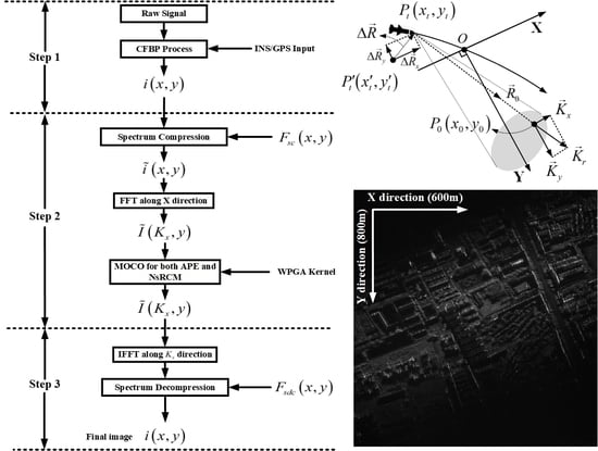
5. Processing Procedures

The processing procedures of data-driven MOCO combined with CFBP is summarized in Figure 6, which includes three main steps.
Step 1: CFBP processing. In the first step, the raw echoed signal collected in missile-borne SAR sensor will be preprocessed, e.g., range compressing or range deramp processing. Then, the pre-processed signal is processed by CFBP for imagery. The on-board inertial navigation system/global positioning system (INS/GPS) information is readily incorporated into CFBP for preliminary MOCO. If the INS/GPS is not accurate enough, the proposed MOCO algorithm is utilized to compensate for the unknown motion error in a data-driven manner. It is noted that the Nyquist sample rate in every recursion in CFBP needs to be high enough, so that the information of both echoed signal and motion error will be fully contained and transformed in the images in every recursion, and only the image obtained from final recursion is utilized for the MOCO process. After step 1, the coarsely focused image of i x , y from CFBP is obtained.
Step 2: Spectrum compression and MOCO. In the second step, the image obtained from CFBP is transformed into a spectrum-compressed domain by utilizing spectrum compression according to (19). Then, the image is transformed into phase history domain, i.e., I ˜ K x , y domain, by applying fast Fourier transformation (FFT) along the x-direction. Because the echoes from different scatterers have nearly the same spectrum range along K x direction, classic weighted PGA (WPGA) [35] is processed with high efficiency and effectiveness. It is also noted that both azimuth phase error (APE) and nonsystematic range cell migration (NsRCM) need to be considered in the MOCO for high-accuracy estimation and compensation, and the compensated image of I ˜ M O C O K x , y is obtained. The compensation for NsRCM can be referred to [31,36].
Step 3: After both APE and NsRCM are compensated in phase history domain, the images are transformed back into the x , y domain by utilizing inverse FFT (IFFT) along the K x direction. Then, the image is transformed into x , y domain and a spectrum-decompression is applied to the image to preserve the phase information. The spectrum-decompression function is a conjunction of spectrum-compression function, given as
F s d c x , y = exp j K r c x 2 + y 2 .
After spectrum-decompression, the image of i M O C O x , y with high focusing quality is finally obtained.

6. Simulations and Raw Data Experiments

In this section, both simulations for missile-borne SAR and raw data experiments of highly-squint airborne SAR are presented to evaluate the performance of the proposed algorithm.

6.1. Simulations for Missile-Borne SAR

In this sub-section, simulation experiments are presented and analyzed to evaluate the performance of the data-driven MOCO. The missile-borne SAR geometry for the simulation is according to Figure 3, and nine point scatterers in the observing scene for analyzing is according to Table 2. The parameters are according to Table 1. Figure 7 shows the assumed motion errors of the missile platform in both x- and y-directions.
The algorithms for the simulation experiments are programmed on a MATLAB platform and Windows 10 system on a desktop computer with an i7-9700 CPU and 32 GB RAM without parallel processing. The total processing time using direct BP is approximately 175 min. The total processing time by using conventional FFBP is approximately 11.4 min. The total processing time using the algorithm of [27] is about 4.1 min. The total processing time by using the proposed MOCO combined with CFBP is approximately 2.7 min. It can be seen that the proposed MOCO with CFBP is much faster than direct BP and FFBP algorithms, as well as the algorithm of [27]. In Figure 3, point 5 is regarded as the center point while point 3 is regarded as the frontier point, and the results of both center and frontier points are particularly analyzed. In the MOCO process, the phase error varying along range direction is also considered and compensated according to [29].
Figure 8 presents the focusing results of the center point and frontier point obtained from the CFBP algorithm without any MOCO. The results degraded seriously along the azimuth direction due to the unknown motion error, and the defocusing results bring difficulty to the subsequent process. Figure 9 presents the focusing results of the center point and frontier point obtained from CFBP algorithm in which the MOCO is processed without spectrum compression. From Figure 9, it can be seen that both center and frontier points still have some defocusing. Because the echoes from different point scatterers have a different spectrum range along the K x direction and the phase error is spatially variant, the phase error cannot be exactly estimated and compensated. Figure 10 presents the focusing results of the center point and frontier point obtained from the MOCO algorithm of [27]. Table 3 presents the –3 dB main-lobe, the peak-sidelobe ration (PSLR) and the integrated sidelobe ratio (ISLR) for the focusing quality analyses of the nine point scatterers. Because the spatial-variant phase error cannot be accurately compensated, minor defocusing still remains in the final image. Figure 11 presents the focusing results of the center point and frontier point obtained from CFBP algorithm in which the MOCO is processed after spectrum compression. From Figure 11, it can be seen that the focusing performance of the proposed algorithm obtains high focusing performance, where the processing results have a narrower main-lobe and lower sidelobes. The –3 dB main-lobe, the peak-sidelobe ration (PSLR) and the integrated sidelobe ratio (ISLR) for the focusing quality analyses of the nine point scatterers are listed in Table 4. The high focusing quality demonstrates the superior performance of the proposed MOCO for missile-borne SAR application.

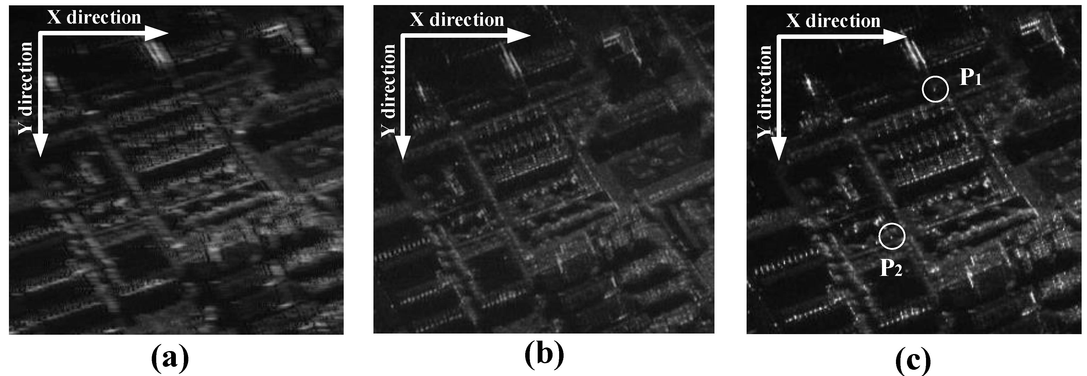
6.2. Raw Data Experiments for Airborne SAR

To further evaluate the performance of the proposed algorithm, raw data experiments from a maneuvering highly-squint airborne SAR system are implemented by utilizing the proposed MOCO with CFBP algorithm. The airborne SAR is operating in a Ka band with a bandwidth of 200 MHz. The range center is about 7000 m. The forward velocity of the airborne platform is about 60 m/s and the downward velocity of the airborne platform is about 1.1 m/s. The squint angle is about 45 degrees. Because the on-board INS/GPS information is not accurate enough, data-driven MOCO is processed with CFBP. By using the proposed MOCO, the estimated motion error of the airborne platform is shown in Figure 12. From Figure 12, it can be seen that the motion error exceeds one quarter of the scale of wavelength, which needs to be compensated in the CFBP process.
The focusing results are provided in Figure 13. The size of the final SAR image in terms of X × Y is 600 m × 800 m. Figure 13a is the result obtained by the CFBP algorithm without any MOCO, and it can be seen that the image is degraded seriously with the image entropy of 11.203 . Figure 13b is the results obtained by data-driven MOCO in CFBP, but the MOCO is not in a spectrum-compressed domain. From Figure 13b, it can be seen that obvious defocusing remains in the image with the image entropy of 10.751 . Figure 13c is the results obtained from the algorithm of [27]. Because the spatial-variant phase error cannot be accurately compensated, minor defocusing still remains in the final image with the entropy of 10.662 . Figure 13d is the results obtained from the proposed algorithm in which the data-driven MOCO is processed in spectrum-compressed domain, also combined with the CFBP algorithm. From Figure 13d, it can be seen that the algorithm achieves the highest focusing quality with image entropy of 10.628 . Figure 14 compares the zoomed images. It is shown that the buildings as well as the roads can be clearly distinguished in the SAR image, which shows that the proposed MOCO algorithm can effectively compensate the unknown motion error to achieve better performance. Figure 15 compares the azimuth responses of two focused prominent scatterers. The azimuth resolution obtained from the algorithm of [27] is about 0.125 m, while the azimuth resolution obtained from the proposed algorithm is about 0.110 m. From the comparison, it can be seen that the proposed algorithm can achieve higher focusing quality, which validates the superior performance of the proposed algorithm.

7. Conclusions

In this paper, a new data-driven MOCO algorithm is developed under the CFBP framework for missile-borne SAR application. The SAR image from CFBP is transformed into a spectrum-compressed domain where the echoes from different scatterering points are aligned in the same spectrum range in a spectrum-compressed domain, and the phase error can be regarded as spatially invariant. With this inherent characteristic of spectrum-compressed domain, an effective data-driven MOCO algorithm is developed with CFBP algorithm for accurate error estimation and compensation. Results from simulations and raw data experiments are presented to validate the performance of the proposed algorithm.

Author Contributions

M.B. developed the proposed algorithm and wrote the manuscript. M.B. and S.Z. conducted the experiments and organized the manuscript. M.X. commented on the manuscript and made useful suggestions. All authors have read and agreed to the published version of the manuscript.

Funding

This work was supported in part by the National Key R & D Program of China under Grant 2018YFC0810202, and in part by Fire and Rescue Department technology Program of MEM under Grant 2020XFZD05, and in part by the National Natural Science Foundation of China under Grant Nos. 61201284, 61801204, and 62061031, and in part by Shaanxi Innovative Talents Promotion Plan-Science and Technology Innovation Team under Grant No. 2019TD-002, and in part by the public foundation from the Key Laboratory of EMW Information, Fudan University, China, under Grant No. EMW201901.

Institutional Review Board Statement

Not applicable.

Informed Consent Statement

Not applicable.

Data Availability Statement

Not applicable.

Conflicts of Interest

The authors declare no conflict of interest.

Abbreviations

The following abbreviations are used in this manuscript:
LDlinear dichroism
SARsynthetic aperture radar
FFBPfast factorized back-projection
CFBPCartesian factorized back projection
MOCOmotion compensation
FDAfrequency-domain algorithm
TDAtime-domain algorithm
RDArange-doppler algorithm
CSAchirp-scaling algorithm
BPback-projection
INS/GPSinertial navigation system/global positioning system
UAVunmanned aerial vehicle
FTFourier transformation
SAsub image
POSPprinciple of stationary phase
PGAphase gradient autofocusing
MDAmap-drift autofocusing
WPGAweighted PGA
APCantenna phase center
NsRCMnonsystematic range cell migration
PRFpulse repetition frequency
PSLRpeak sidelobe ratio
ISLRintegrated sidelobe ratio

References

  1. Zink, M.; Moreira, A.; Hajnsek, I.; Rizzoli, P.; Bachmann, M.; Kahle, R.; Fritz, T.; Huber, M.; Krieger, G.; Lachaise, M. TanDEM-X: 10 Years of Formation Flying Bistatic SAR Interferometry. IEEE J. Sel. Top. Appl. Earth Obs. Remote Sens. 2021, 14, 3546–3565. [Google Scholar] [CrossRef]
  2. Wan, J.; Tan, X.; Chen, Z.; Dong, L.; Liu, Q.; Zhou, Y.; Zhang, L. Refocusing of Ground Moving Targets with Doppler Ambiguity Using Keystone Transform and Modified Second-Order Keystone Transform for Synthetic Aperture Radar. Remote Sens. 2021, 2, 177. [Google Scholar] [CrossRef]
  3. Freeman, A.; Zink, M.; Caro, E.; Moreira, A.; Veilleux, L.; Werner, M. The legacy of the SIR-C/X-SAR radar system: 25 years on. Remote Sens. Environ. 2019, 231, 111255. [Google Scholar] [CrossRef]
  4. Luebeck, D.; Wimmer, C.; Moreira, L.F.; Alcântara, M.; Oré, G.; Góes, J.A.; Oliveira, L.P.; Teruel, B.; Bins, L.S.; Gabrielli, L.H. Drone-borne differential SAR interferometry. Sensors 2020, 12, 778. [Google Scholar] [CrossRef] [Green Version]
  5. Bie, B.; Sun, G.C.; Xia, X.G.; Xing, M.; Guo, L.; Bao, Z. High-speed maneuvering platforms squint beam-steering SAR imaging without subaperture. IEEE Trans. Geosci. Remote Sens. 2019, 57, 6974–6985. [Google Scholar] [CrossRef]
  6. Li, G.; Ma, Y.; Xiong, X. Maneuvering platform high-squint SAR imaging method based on perturbation KT and subregion phase filtering. J. Appl. Remote Sens. 2021, 1, 016502. [Google Scholar]
  7. Feng, D.; An, D.; Huang, X. An extended fast factorized back projection algorithm for missile-borne bistatic forward-looking SAR imaging. IEEE Trans. Aerosp. Electron. Syst. 2018, 54, 2724–2734. [Google Scholar] [CrossRef]
  8. Tang, S.; Guo, P.; Zhang, L.; Lin, C. Modeling and Precise Processing for Spaceborne Transmitter/Missile-Borne Receiver SAR Signals. Remote Sens. 2019, 11, 346. [Google Scholar] [CrossRef] [Green Version]
  9. Li, X.; Zhou, S.; Yang, L. A New Fast Factorized Back-Projection Algorithm with Reduced Topography Sensibility for Missile-Borne SAR Focusing with Diving Movement. Remote Sens. 2020, 16, 2616. [Google Scholar] [CrossRef]
  10. Cumming, I.G.; Wong, F.H. Digital Signal Processing of Synthetic Aperture Radar Data: Algorithms and Implementation; Artech House: Norwood, MA, USA, 2004. [Google Scholar]
  11. Chen, J.; Xing, M.; Sun, G.; Li, Z. A 2D space-variant motion estimation and compensation method for ultrahigh-resolution airborne stepped-frequency SAR with long integration time. IEEE Trans. Geosci. Remote Sens. 2017, 55, 6390–6401. [Google Scholar] [CrossRef]
  12. Rodriguez-Cassola, M.; Prats, P.; Krieger, G.; Moreira, A. Efficient time-domain image formation with precise topography accommodation for general bistatic SAR configurations. IEEE Trans. Aerosp. Electron. Syst. 2011, 47, 2949–2966. [Google Scholar] [CrossRef] [Green Version]
  13. Desai, M.D.; Jenkins, W.K. Convolution backprojection image reconstruction for spotlight mode synthetic aperture radar. IEEE Trans. Image Process. 1992, 1, 505–517. [Google Scholar] [CrossRef] [PubMed]
  14. Zhang, Y.; Zhang, Q.; Zhang, Y.; Pei, J.; Huang, Y.; Yang, J. Fast split bregman based deconvolution algorithm for airborne radar imaging. Remote Sens. 2020, 12, 1747. [Google Scholar] [CrossRef]
  15. Gaibel, A.; Boag, A. Backprojection Imaging of Moving Objects. IEEE Trans. Image Process. 2020. [Google Scholar] [CrossRef]
  16. Lin, C.; Tang, S.; Zhang, L.; Guo, P. Focusing High-Resolution Airborne SAR with Topography Variations Using an Extended BPA Based on a Time/Frequency Rotation Principle. Remote Sens. 2018, 8, 1275. [Google Scholar] [CrossRef] [Green Version]
  17. Zhang, L.; Li, H.L.; Qiao, Z.J.; Xing, M.D.; Bao, Z. Integrating autofocus techniques with fast factorized back-projection for high-resolution spotlight SAR imaging. IEEE Geosci. Remote Sens. Lett. 2013, 10, 1394–1398. [Google Scholar] [CrossRef]
  18. Mao, X.; Ding, L.; Zhang, Y.; Zhan, R.; Li, S. Knowledge-Aided 2D Autofocus for Spotlight SAR Filtered Backprojection Imagery. IEEE Trans. Geosci. Remote Sens. 2019, 57, 9041–9058. [Google Scholar] [CrossRef]
  19. Ulander, L.M.H.; Hellsten, H.; Stenstrom, G. Synthetic-aperture radar processing using fast factorized back-projection. IEEE Trans. Aerosp. Electron. Syst. 2003, 39, 760–776. [Google Scholar] [CrossRef] [Green Version]
  20. Shippey, G.; Banks, S.; Pihl, J. SAS image reconstruction using fast polar back projection: Comparisons with fast factored back projection and Fourier-domain imaging. Eur. Ocean. 2005, 1, 96–101. [Google Scholar]
  21. Yang, Z.; Sun, G.-C.; Xing, M. A new fast back-projection algorithm using polar format algorithm. In Proceedings of the 2013 Asia-Pacific Conference on Synthetic Aperture Radar (APSAR), Tsukuba, Japan, 23–27 September 2013; Volume 1, pp. 373–376. [Google Scholar]
  22. Vu, V.T.; Pettersson, M.I. Nyquist sampling requirements for polar grids in bistatic time-domain algorithms. IEEE Trans. Signal Process. 2014, 63, 457–465. [Google Scholar] [CrossRef]
  23. Zhou, S.; Yang, L.; Zhao, L.; Wang, Y.; Zhou, H.; Chen, L.; Xing, M. A New Fast Factorized Back Projection Algorithm for Bistatic Forward-Looking SAR Imaging Based on Orthogonal Elliptical Polar Coordinate. IEEE J. Sel. Top. Appl. Earth Obs. Remote Sens. 2019, 12, 1508–1520. [Google Scholar] [CrossRef]
  24. Dong, Q.; Sun, G.; Yang, Z.; Guo, L.; Xing, M. Cartesian factorized backprojection algorithm for high-resolution spotlight SAR imaging. IEEE Sens. J. 2017, 3, 1160–1168. [Google Scholar] [CrossRef]
  25. Luo, Y.; Zhao, F.; Li, N.; Zhang, H. A modified cartesian factorized back-projection algorithm for highly squint spotlight synthetic aperture radar imaging. IEEE Geosci. Remote Sens. Lett. 2018, 6, 902–906. [Google Scholar] [CrossRef]
  26. Chen, X.; Sun, G.; Xing, M.; Li, B.; Yang, J.; Bao, Z. Ground Cartesian Back-Projection Algorithm for High Squint Diving TOPS SAR Imaging. IEEE Trans. Geosci. Remote Sens. 2020. [Google Scholar] [CrossRef]
  27. Luo, Y.; Zhao, F.; Li, N.; Zhang, H. An autofocus cartesian factorized backprojection algorithm for spotlight synthetic aperture radar imaging. IEEE Geosci. Remote Sens. Lett. 2018, 8, 1244–1248. [Google Scholar] [CrossRef]
  28. Xing, M.; Jiang, X.; Wu, R.; Zhou, F.; Bao, Z. Motion compensation for UAV SAR based on raw radar data. IEEE Trans. Geosci. Remote Sens. 2009, 8, 2870–2883. [Google Scholar] [CrossRef]
  29. Zhang, L.; Qiao, Z.; Xing, M.; Yang, L.; Bao, Z. A robust motion compensation approach for UAV SAR imagery. IEEE Trans. Geosci. Remote Sens. 2012, 8, 3202–3218. [Google Scholar] [CrossRef]
  30. Pu, W. Deep SAR Imaging and Motion Compensation. IEEE Trans. Image Process. 2021, 30, 2232–2247. [Google Scholar] [CrossRef]
  31. Zhou, S.; Yang, L.; Zhao, L.; Bi, G. Quasi-polar-based FFBP algorithm for miniature UAV SAR imaging without navigational data. IEEE Trans. Geosci. Remote Sens. 2017, 55, 7053–7065. [Google Scholar] [CrossRef]
  32. Pu, W.; Wu, J.; Huang, Y.; Yang, J.; Yang, H. Fast Factorized Backprojection Imaging Algorithm Integrated With Motion Trajectory Estimation for Bistatic Forward-Looking SAR. IEEE J. Sel. Top. Appl. Earth Obs. Remote Sens. 2019, 12, 3949–3965. [Google Scholar] [CrossRef]
  33. Yang, L.; Li, P.; Zhang, S.; Zhao, L.; Zhou, S.; Xing, M. Cooperative Multitask Learning for Sparsity-Driven SAR Imagery and Nonsystematic Error Autocalibration. IEEE Trans. Geosci. Remote Sens. 2020, 58, 5132–5147. [Google Scholar] [CrossRef]
  34. Wahl, D.; Eichel, P.H.; Ghiglia, D.C.; Jakowatz, C.V. Phase gradient autofocus-a robust tool for high resolution SAR phase correction. IEEE Trans. Aerosp. Electron. Syst. 1994, 3, 827–835. [Google Scholar] [CrossRef] [Green Version]
  35. Ye, W.; Yeo, T.; Bao, Z. Weighted least-squares estimation of phase errors for SAR/ISAR autofocus. IEEE Trans. Geosci. Remote Sens. 1999, 5, 2487–2494. [Google Scholar] [CrossRef] [Green Version]
  36. Bao, M.; Zhou, S.; Yang, L.; Xing, M.; Zhao, L. Data-driven Motion Compensation for Airborne Bistatic SAR Imagery under Fast Factorized Back Projection Framework. IEEE J. Sel. Top. Appl. Earth Obs. Remote Sens. 2021, 14, 1728–1740. [Google Scholar] [CrossRef]
Figure 1. Missile-borne SAR geometry.
Remotesensing 13 01462 g001
Figure 2. Wavenumber decomposition.
Remotesensing 13 01462 g002
Figure 3. Geometry and point locations.
Remotesensing 13 01462 g003
Figure 4. Image spectrum of nine point scatterers after the CFBP process.
Remotesensing 13 01462 g004
Figure 5. Image spectrum of nine point scatterers in a spectrum-compressed domain.
Remotesensing 13 01462 g005
Figure 6. Processing procedures.
Remotesensing 13 01462 g006
Figure 7. Assumed motion errors in x- and y-directions.
Remotesensing 13 01462 g007
Figure 8. Results from CFBP without any MOCO. (a) Focusing results of center point and its azimuth responses; (b) focusing results of frontier point and its azimuth responses.
Remotesensing 13 01462 g008
Figure 9. Results from CFBP and MOCO are processed without spectrum compression. (a) Focusing results of center point and its azimuth responses; (b) focusing results of frontier point and its azimuth responses.
Remotesensing 13 01462 g009
Figure 10. Results from the algorithm of reference [27]. (a) Focusing results of center point and its azimuth responses; (b) focusing results of frontier point and its azimuth responses.
Remotesensing 13 01462 g010
Figure 11. Results from the proposed algorithm. (a) Focusing results of center point and its azimuth responses; (b) focusing results of frontier point and its azimuth responses.
Remotesensing 13 01462 g011
Figure 12. Motion error of airborne platform estimated from echoes.
Remotesensing 13 01462 g012
Figure 13. Experimental results from highly-squint airborne SAR. (a) Obtained results from CFBP algorithm without any MOCO; (b) obtained results from CFBP algorithm combined with data-driven MOCO but without spectrum compression; (c) obtained results from the algorithm of [27]; (d) obtained results from the proposed algorithm.
Remotesensing 13 01462 g013
Figure 14. Zoomed images for comparison. (a) Obtained results from CFBP algorithm combined with data-driven MOCO but without spectrum compression; (b) obtained results from the algorithm of [27]; (c) obtained results from the proposed algorithm.
Remotesensing 13 01462 g014
Figure 15. Azimuth responses of the prominent scatterers of P 1 and P 2 . The dashed lines denote the results from the algorithm of [27], and the solid lines denote the results from the proposed algorithm.
Remotesensing 13 01462 g015
Table 1. Parameters of a missile-borne SAR system.
Wave BandKu
Bandwidth180 MHz
Range Centerabout 10,000 m
Velocity in the x-Direction500 m/s
Acceleration in x-Direction−15 m/s 2
Velocity in y-Direction120 m/s
Acceleration in y-Direction−12 m/s 2
Synthetic Duration0.5 s
Table 2. The locations of the point scatterers.
PointXY
Point 1−500 m9600 m
Point 2−500 m10,100 m
Point 3−500 m10,600 m
Point 40 m9500 m
Point 50 m10,000 m
Point 60 m10,500 m
Point 7500 m9400 m
Point 8500 m9900 m
Point 9500 m10,400 m
Table 3. The focusing quality of the point scatterers from the algorithm of [27].
y-Direction
Point3-dB widthPSLRISLR
Point 10.86 m−12.91 dB−9.98 dB
Point 20.85 m−13.11 dB−9.91 dB
Point 30.86 m−13.02 dB−9.84 dB
Point 40.85 m−13.10 dB−9.88 dB
Point 50.85 m−13.05 dB−9.89 dB
Point 60.86 m−13.02 dB−9.91 dB
Point 70.86 m−12.94 dB−9.77 dB
Point 80.87 m−13.12 dB−9.84 dB
Point 90.87 m−13.07 dB−9.81 dB
x-Direction
Point3-dB widthPSLRISLR
Point 10.48 m−11.68 dB−9.67 dB
Point 20.47 m−11.83 dB−9.49 dB
Point 30.53 m−11.64 dB−9.57 dB
Point 40.45 m−12.04 dB−9.48 dB
Point 50.46 m−12.17 dB−9.37 dB
Point 60.47 m−11.41 dB−9.60 dB
Point 70.49 m−10.79 dB−9.43 dB
Point 80.52 m−11.80 dB−9.40 dB
Point 90.52 m−12.24 dB−9.59 dB
Table 4. The focusing quality of the point scatterers from the proposed algorithm.
y-Direction
Point3-dB widthPSLRISLR
Point 10.86 m−13.11 dB−9.88 dB
Point 20.85 m−12.99 dB−9.98 dB
Point 30.86 m−13.09 dB−9.87 dB
Point 40.85 m−13.11 dB−9.99 dB
Point 50.85 m−13.10 dB−9.97 dB
Point 60.86 m−12.96 dB−9.84 dB
Point 70.86 m−13.01 dB−9.88 dB
Point 80.87 m−13.02 dB−9.76 dB
Point 90.87 m−13.13 dB−9.93 dB
x-Direction
Point3-dB widthPSLRISLR
Point 10.46 m−12.91 dB−9.78 dB
Point 20.48 m−13.03 dB−9.87 dB
Point 30.51 m−12.91 dB−9.91 dB
Point 40.43 m−13.03 dB−9.93 dB
Point 50.43 m−13.02 dB−9.92 dB
Point 60.46 m−12.99 dB−9.87 dB
Point 70.48 m−12.91 dB−9.81 dB
Point 80.50 m−13.00 dB−9.89 dB
Point 90.51 m−12.89 dB−9.79 dB
Publisher’s Note: MDPI stays neutral with regard to jurisdictional claims in published maps and institutional affiliations.

