Article

Detection of the Minute Variations of Total Suspended Matter in Strong Tidal Waters Based on GaoFen-4 Satellite Data

1
State Key Laboratory of Tropical Oceanography, South China Sea Institute of Oceanology, Chinese Academy of Sciences, Guangzhou 510301, China
2
University of Chinese Academy of Sciences, Beijing 100049, China
3
Institute of Remote Sensing and Earth Sciences, College of Science, Hangzhou Normal University, Hangzhou 311121, China
4
Southern Marine Science and Engineering Guangdong Laboratory (Guangzhou), Guangzhou 511458, China
*
Author to whom correspondence should be addressed.
Remote Sens. 2021, 13(7), 1339; https://doi.org/10.3390/rs13071339
Submission received: 2 March 2021 / Revised: 24 March 2021 / Accepted: 29 March 2021 / Published: 31 March 2021

Abstract

:
Hangzhou Bay (HZB) is the largest macro-tidal bay in China, where suspended sediment concentrations are significantly modulated by tidal oscillations. This makes it an ideal area for the study of the impact of tide on temporal–spatial variation in suspended sediment. The GaoFen-4 (GF-4) satellite is the first high-resolution geosynchronous orbiting satellite of China. It exhibits the unique advantages of capturing minute variations and finer details of total suspended matter (TSM) due to the enhancement in spatial resolution (50 m) and observation time interval (20 s). In this study, TSM concentration of the HZB was retrieved based on the GF-4 satellite. The spatial distribution and minute variations of TSM concentration under the ebb tide from 7:30 to 7:40 a.m. on 28 August 2017, were analyzed. The results showed that the average TSM concentration inside HZB was (371.8 ± 1.8) mg/L. There was a linearly increasing trend of TSM concentration at ebb tide, with an increment of (3.96 ± 0.31) (mg/L)/min, and a more significant increase was observed in the high TSM areas. This increase in TSM concentration was associated with both the bottom topography and tide processes. The tidal potential energy generated by the tidal range and the strong shear stress generated by the high current velocity both led to the re-suspension of the sedimentary particles, which affected the variation of TSM concentration. In addition, the influence of bottom topography changed the intensity of re-suspension and also affected the distribution of TSM concentration in HZB.

Graphical Abstract

1. Introduction

Suspended sediments can affect the water quality, ecosystem, and bottom geomorphologic evolution in estuaries and bays [1,2]. They are an important indicator of the sediment transport and resuspension process [3,4]. The exchanges of particles such as sediment can be influenced by the tide in estuaries and bays [5]. Total suspended matter (TSM) concentration therefore provides great reference for tidal prediction, disaster warning, marine engineering construction, and underwater equipment design in strong tidal area.
The study of the inter-annual, annual, and monthly variations of TSM concentration in strong-tidal estuary, gulf, and other sea areas has been widely reported in previous literatures [6,7,8,9,10,11]. Using traditional in-situ measurement, it is difficult to detect the TSM concentration on a timely basis and on a large scale [12,13]. The satellite can provide global water leaving radiance from the sea surface, so as to provide continuous observation of TSM [11,14]. Early TSM concentration was mostly retrieved by Landsat-x_MSS [6,15], NIMBUS-7_CZCS [16], and SeaStar_SeaWiFs [8,17] satellite sensors. With the progress of optical sensor design technology, the MODIS [18,19], MERIS [9,10,20], sentinel-2A/B [11], sentinel-3_OLCI [21], and VIIRS [22] have been used widely to study the spatial and temporal change trends of TSM concentration in near shore and in large lakes. However, for highly turbid waters such as estuaries and coastal areas with significant hourly-varying characteristics, polar orbit satellites with high spatial resolution and low temporal resolution cannot meet the dynamic monitoring requirements.
In recent years, a geostationary orbit satellite has been introduced into the research. The Geostationary Ocean Color Imager (GOCI) satellite has been used to describe the diurnal variation characteristics of TSM concentration in estuaries and inshore and coastal waters [23,24,25,26]. However, the spatial resolution GOCI is 500 meters at nadir, and the image of the GOCI satellite only covers the partial sea area centered on the Korean peninsula. It is not easy to use GOCI to study the TSM distribution in small bays and coastal regions. In order to improve the low spatial resolution of GOCI image, Pan et al. [27] proposed to conduct multi-source data fusion between Landsat OLI (30 m, 16 days) and GOCI (500 m, 1 h), and the fusion results could more accurately reflect the diurnal variation characteristics of TSM. Furthermore, water conservancy, waterway, and sea reclamation projects have put forward higher requirements for the understanding of the basic law of suspended particulate transport in high-tide waters, which should have higher-frequency variations that are sometimes located in a small region. However, at present, no research has been proposed to describe higher temporal variability of TSM concentration than GOCI.
Higher temporal and spatial resolution are needed to advance the understanding of variation processes of TSM concentration under the impact of tide. GaoFen-4 (GF-4), launched in December 2015, is the first high-resolution geosynchronous orbiting satellite of China. The GF-4 satellite provides a finer resolution observation at 50 m spatial resolution. Due to the enhancement in spatial resolution, it allows the identification of the finer details of TSM in estuaries and bays. The GF-4 observes the earth surface every 20 s. This makes it possible to study high-frequency changes of TSM [28,29,30]. Furthermore, the spatial coverage of the GF-4 satellite extends to more estuaries and bays of China. In this paper, the TSM distribution and the current in the Hangzhou bay (HZB) were firstly retrieved from the GF-4 top of atmosphere (TOA) reflectance images. Then, the minute variability of TSM concentration and its mechanism was analyzed.

2. Materials and Methods

2.1. Study Area

The HZB, located in the northeast of Zhejiang province (29–31° N, 121–123° E), is the largest marginal bay along the southeast coast of China and an important transition zone between sea and land connecting the East China Sea, as shown in Figure 1. The bay is wide and shallow, with a total area of about 8500 km2, an average water depth of 8–10 m, a length of about 86 km, and a rapid change in width, from 100 km at the mouth of the bay to only 20 km at its narrowest point [31]. HZB is part of the mouth of the Qiantang River, to the north of which lies China’s longest river, the Yangtze River. The Qiantang river and the adjacent Yangtze river in the north are the main freshwater resources entering the HZB, where the freshwater runoff is 42 and 925 km3/a, respectively. Due to the erosion of these two river basins, millions of tons of sediments are discharged into the bay every year. Among them, the Qiantang river receives about 7.9 × 10⁶ tons of sediment each year [19], and 3.1% of the total sediment from the Yangtze river to the East China Sea is carried into the HZB by the south branch of the Yangtze river, which receives about 4.8 × 10⁸ tons annually [32]. Under the influence of the complex dynamic processes, such as the south branch current of the Yangtze estuary, the runoff of the Qiantang River, and the tide of the East China Sea, the study area has typical characteristics of a strong tidal area. The tidal type of HZB is a regular semi-diurnal tide. The M2 constituent (Table 1) is the dominant tidal component of HZB. Its seabed is an undulating and shrinking plane, and the tidal range increases rapidly from east to west. The average tidal range is 3–4 m at the mouth of the bay and 4–6 m within the bay, and the tidal peak at the mouth of the Qiantang River can reach 8.93 m. HZB is one of the most remarkable tidal bays in the world [13,32,33].
Due to strong tides and rapid water flow, a large number of suspended particles are deposited in HZB [34], which is characterized by significant periodic changes in sediment concentration [23,25,26]. Within a tidal cycle, the significant changes of TSM occur in the middle and later periods of high tide and low tide [24].

2.2. Data Sources

The GaoFen series satellites, which were designed to collect land atmosphere and ocean high resolution imageries and to form all-weather and all-day global coverage of earth observation capability by China with 13 satellites, launched from 2013. The GF-4 satellite was launched in 2015 with the sensors of a staring camera, which has a 50 m’ spatial resolution in visible or near infrared bands (bands 1–5) or 400 m’ spatial resolution in the thermal infrared band (band 6). The GF-4 satellite is a geostationary satellite, and the temporal resolution is 20 s. The width of each GF-4 image is 40 km. Gf-4 data have a super high spatial and temporal resolution, which is suitable for the high frequency change study of TSM in the high turbidity sea area. Due to the limitations of transmission and data storage technology, the time interval of the data products provided is about 1 min. In this paper, we used the GF-4 satellite PMS L1A data from 7:30:00 a.m. to 7:40:00 a.m. on 28 August 2017, provided by China Centre for Resources Satellite Data and Application.
The field observation data were measured at the cruise during 2 to 13 December 2011, and 16 to 22 May 2014. The spectra of in-situ Rrs were obtained by using a hand-held analytical spectral devices (ASD) spectrometer and a standard board of 30% reflectance. The in-situ TSM concentration was collected by a standard sampler and measured by the filtration gravimetric method. From each station, two parallel samples were collected and the TSM concentration was measured, respectively. The average TSM concentration of the two parallel samples was derived as the in-situ TSM concentration of the station. A blank sample was run with each sample to blank correct the data. The 71 effective TSM concentration data were finally used to calibrate the TSM inversion algorithm. The TSM was grouped with the 41 TSM data for SAI (spectral absorption index) model construction and the 30 TSM data for model validation.
The topographic map is the global topographic relief model ETOPO published by U.S. National Geophysical Data Center, which is the highest resolution known topographic relief data [34]. It includes three data with different accuracy, ETOPO1, ETOPO2, and ETOPO5, and there are two versions, the Ice Surface and the Bedrock, the former being the elevation of the ice sheet and the latter giving the elevation of the bedrock. In this paper, the Bedrock version in ETOPO1 (resolution 1 min of arc) with the highest accuracy was selected to map the bottom terrain of HZB.
Regarding the tide level data, looking up the Tide Table [35], the hourly tide level of each tide station during the collection period of GF-4 PMS images (7:00–8:00 a.m. on 28 August 2017) was obtained, and the difference value of the tide level in two adjacent hours was taken as the change of the tide level. Then, the minute change of tide level of the station was obtained after averaging.

2.3. GF-4 Remote Sensing Data Processing

The most common atmospheric correction method for ocean color remote sensing is the algorithm proposed by Gordon, which used the near-infrared (NIR) band as the dark pixel due to its good absorbability [14]. However, turbid waters in coastal regions have a strong scattering ability in the NIR band, so the hypothesis of dark pixels above is invalid [36,37]. Additionally, the algorithm using the short wave infrared (SWIR) band instead of the NIR band has been proven to be suitable for turbid waters because of their strong absorbability in the SWIR band [38,39,40]. Since the GF-4 satellite has no SWIR band, the SWIR-based dark pixel method cannot be used for its atmospheric correction directly. The Visible Infrared Imaging Radiometer Suite (VIIRS), which is on board the Suomi National Polar-Orbiting Partnership (SNPP) satellite, has three SWIR bands with band centers 1238, 1601, and 2257 nm. The quasi-synchronous VIIRS (QSV) data can be used for the atmospheric correction of other sensors in highly turbid waters [41].
The Rrs of corrected reflectance was derived after correction for Rayleigh scattering, gaseous absorption, and aerosol multiple scattering effects following:
t v , λ R r s , λ = π d 2 L λ ( F 0 , λ × cos θ s ) R r , λ R a , λ ,
where Lλ is the TOA radiance measured by the sensor in band λ, d is the Sun–Earth distance at the time of the measurement showing the relative deviation from the average Sun–Earth distance d0 equal to 1 AU, θs is solar zenith angles, F0 is the extraterrestrial solar irradiance for mean Sun–Earth distance d0, Rr,λ is the reflectance of Rayleigh scattering, Ra,λ is the reflectance of aerosol multiple scattering reflectance, and tv,λ is the diffuse transmittance of the atmospheric column. Among them, the Second Simulation of the Satellite Signal in the Solar Spectrum (6S) model [42] was used to estimate Rayleigh reflectance (Rr,λ). The necessary input parameters for the 6S model were image-specific geometrical conditions, atmospheric model for gaseous components, and spectral condition. The estimation of aerosol reflectance (Ra,λ) followed the QSV algorithm. First, the aerosol types and the aerosol optical thickness were estimated using the three shortwave infrared bands of VIIRS, and then the aerosol reflectance at GF-4 observing geometries according to the aerosol properties was calculated. Note that the aerosol look-up-tables (LUTs) for 80 aerosol types constructed by Ahmad et al. [43] are necessary for the QSV algorithm, but these LUTs for the GF-4 are not provided by SeaDas software (https://seadas.gsfc.nasa.gov/, accessed on 2 March 2021); thus, the aerosol reflectance and the diffuse transmittance in the GF-4 bands were estimated using the aerosol LUTs for Hyperspectral Imager for the Coastal Ocean (HICO, 400–900 nm, 128 bands) and the response function of the GF-4 bands. The spectral response function of GF-4 bands was provided by China Centre for Resources Satellite Data and Application.

2.4. Remote Sensing Estimation of TSM Concentration and Current Velocity

2.4.1. The Correction of TSM Algorithm
GF-4 satellite data were used to retrieve TSM concentration. It was estimated based on multi-band remote sensing reflectance combined with spectral index with reference to the SAI algorithm suggested by Liu et al. [25]. This algorithm was based on the measured TSM concentration data in May 2013 and the GOCI images of the same day. It had been verified that it can realize the inversion of TSM concentration in HZB [25].
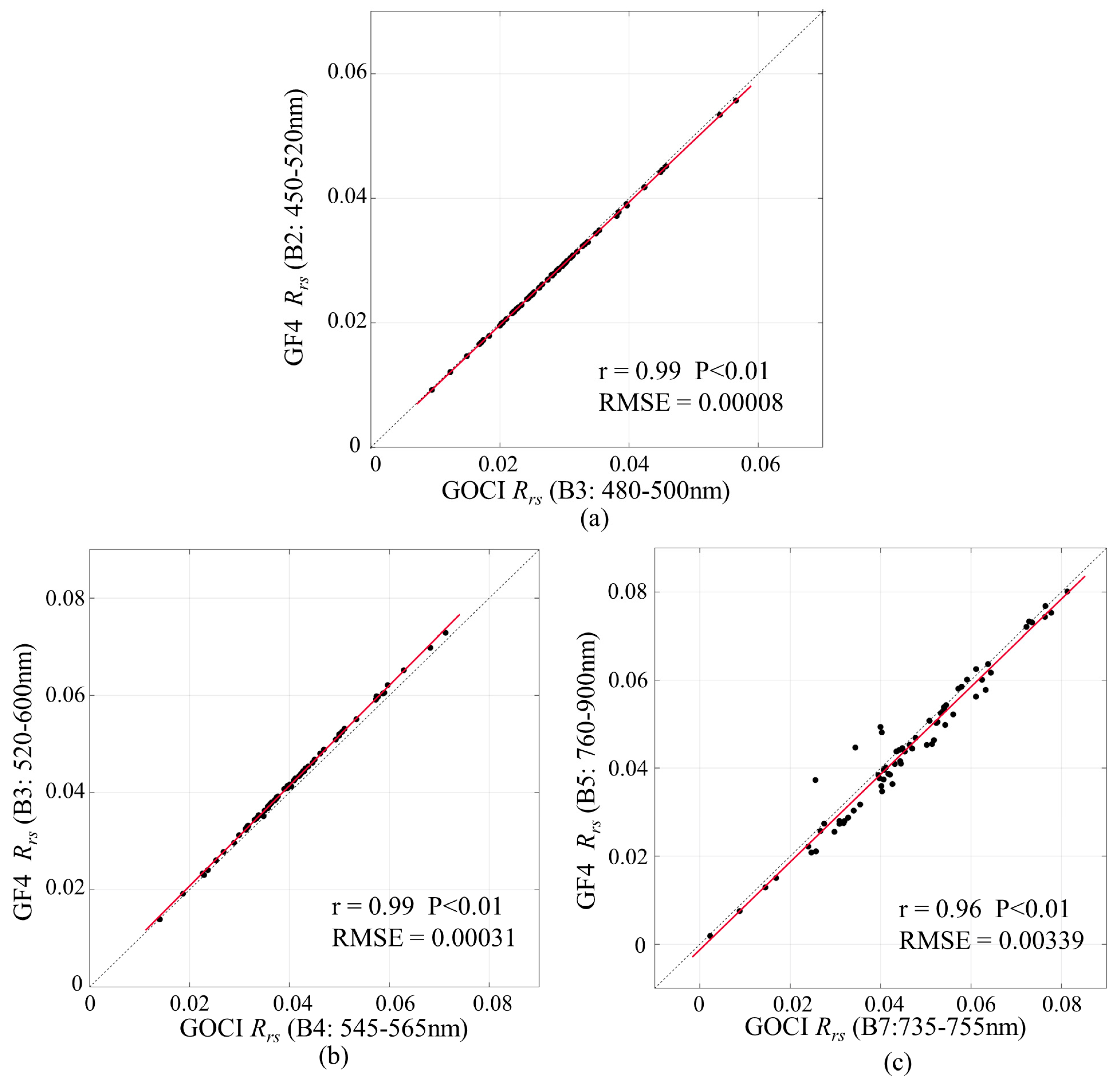
In this paper, the bands Rrs (519), Rrs (550), and Rrs (770) of the GF-4 were used to replace the bands Rrs (490), Rrs (555), and Rrs (745) of the GOCI in original algorithm (Table 2). Since the bands of the GF-4 satellite are different from the corresponding bands of the GOCI satellite in the spectral range and central wavelength, the applicability of the GF-4 bands in the SAI algorithm needs to be verified. According to the spectral range of each band of GF-4 and GOCI satellites, the spectral response function was used to conduct equivalent band processing on the in-situ Rrs. The Rrs of corresponding bands between the GOCI satellite and GF-4 satellite was compared, and the root mean square error (RMSE) and correlation coefficient (r) were used to evaluate the verification results. The verification results showed (Figure 2) that the band of the GOCI and GF-4 satellite had a good fitting result, that is, the bands of the GF-4 can be used for the SAI algorithm. The correlation coefficient of each corresponding band was greater than 0.95. The Rrs can reach up to 0.08 1/Sr in NIR band (Figure 2c), which was consistent with the characteristics of turbidity water. The RMSE of each band increased with the increase of wavelength, that is, the uncertainty of Rrs increased with the increase of wavelength, which may be related to the strong backscattering phenomenon of suspended particulate matter in the NIR band in turbidity water.
Although the verification results showed that the bands of the GF-4 were very similar to the corresponding bands of GOCI, considering the seasonal characteristics of the spatial distribution of TSM concentration in HZB, only the structure of the SAI algorithm was referred, and then the two cruises in-situ data on 2 to 13 December 2011, and 16 to 22 May 2014, were used to correct the coefficients of this algorithm. The in-situ data contained not only TSM, but also the remote sensing reflectance. The in-situ TSM data were grouped with the 41 TSM data for SAI model correction and the 30 TSM data for model validation. The two sets of TSM data have similar numerical ranges, 60–2036 and 156–2238 mg/L, respectively. This large numerical range of TSM data used to develop the algorithm can reflect the response of remote sensing reflectance-derived SAI to TSM variations under different water conditions and concentration levels. These will lead to the algorithm being generally stable and usable.
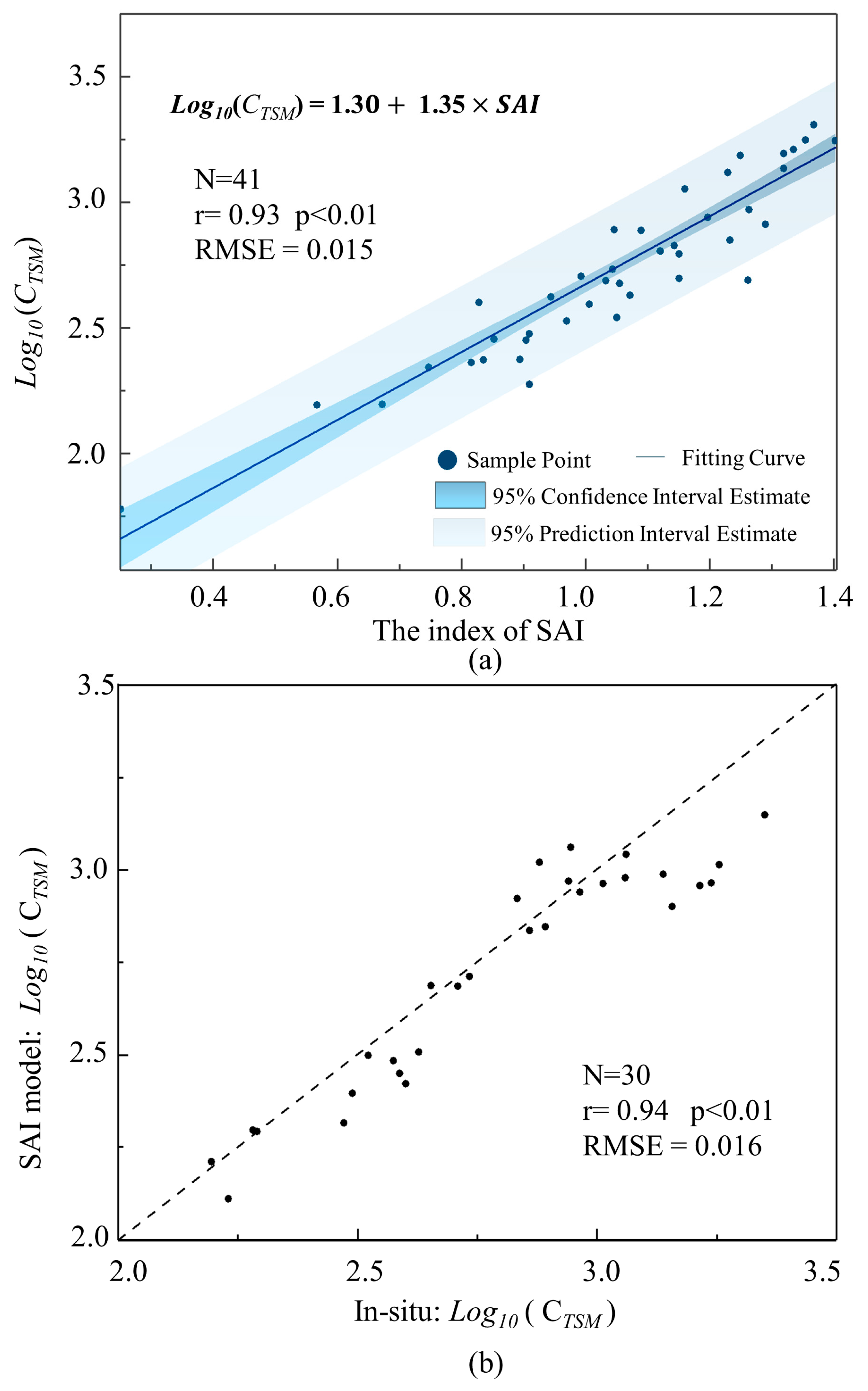
The corrected SAI algorithm is shown in Figure 3a. TSM concentration was calculated by using Equation (2):
log 10 ( C T S M ) = 1.35 × S A I + 1.30 ,
S A I = s × R r s ( 519 ) + ( 1 s ) × R r s ( 770 ) R r s ( 550 ) ,
s = R r s ( 550 ) R r s ( 519 ) R r s ( 770 ) R r s ( 519 ) ,
s is the symmetry of the spectral absorption band used for calculation of the SAI index. Rrs (519), Rrs (550), and Rrs (770) are the remote sensing reflectivity values of corresponding wavelengths of GF-4 images (λ = 519, λ = 550, and λ = 770 nm), respectively. The correlation coefficient was 0.93, the RMSE was 0.015, and the 95% confidence bounds of coefficients were 1.30 ± 0.09 and 1.35 ± 0.08.
The result of model validation was shown as Figure 3b. It was shown that the CTSM calculated by SAI algorithm was consistent with the in-situ CTSM, that is, this algorithm can be used for the inversion of CTSM in HZB by the GF-4 satellite.
Figure 3. (a) The linear regression between the in-situ TSM concentration on the logarithmic scale and the index of the spectral absorption index (SAI). The confidence interval estimation is the estimation interval of the mean value of the dependent variable Log10(CTSM), and the prediction interval estimate is the estimation interval of a single value of the dependent variable Log10(CTSM). (b) The result of model validation. The X axis represents Log10(CTSM) of in-situ sample points, and the Y axis represents Log10(CTSM) of the SAI model calculation. The black dotted lines show the 1:1 relationship.
Remotesensing 13 01339 g003

2.4.2. The Calculation of Average TSM Concentration and Current Velocity

The satellite derived TSM concentration within the range from Ganpu tide station to Lu Chaogang tide station (120°54′E–121°50′E) was averaged as the mean TSM concentration in HZB. Similarly, the TSM concentration within the range from Zhongjun tide station to Shengshan tide station (121°54′E–122°48′E) was averaged as the mean TSM concentration outside HZB.
The TSM difference of two GF-4 remote sensing images with adjacent time was calculated, and the mean value of the difference was calculated as the minute variations of TSM in HZB. The calculation formulas are shown as Equation (3):
Δ C T S M ¯ = C T S M t + 1 C T S M t ,
where Δ C T S M ¯ is the average difference of TSM concentration at two adjacent times (mg/L); C T S M t + 1 and C T S M t are the TSM concentration at the adjacent times (mg/L).
The current velocity was calculated by the tracer measurement method [44] based on the multi-temporal images of the GF-4 satellite. The tracer measurement method takes TSM as the tracer and calculates its moving distance under the action of water flow in a period of time, thus obtaining the velocity of current. Assuming that the time interval of image acquisition is T and the distance of the tracer TSM moving along two mutually perpendicular directions ( x , y ) is Δx and Δy, respectively, then the current velocity can be expressed as Equation (4):
v x = Δ x T ,
v y = Δ y T ,
where the moving distance Δx and Δy was calculated by the maximum likelihood method [44,45,46]. The algorithm is as follows: a window of a × a was selected based on the point f 1 ( x i , y j ) of the image at the initial moment, and the correlation coefficient was calculated by traversing the image at the end moment. Taking the maximum correlation coefficient as the matching coefficient of window a × a , then the corresponding point f 10 ( x i + Δ x , y j + Δ y ) was regarded as the position after moving. The matching coefficients r a , i , j of different windows ( a = 11 , 13 , , 51 ) were calculated, respectively. The window a × a corresponding to the maximum matching coefficient r max was the optimal window; Δx and Δy corresponding to the maximum matching coefficient were the moving distance of the point f 1 ( x i , y j ) . If the maximum matching coefficient is less than 0.5, the current velocity at this point is considered invalid. The calculation formula is Equation (5):
r max = max ( max ( r a , i , j ) ) ,
r a , i , j = ( f 1 ( x i , y j ) f 1 ¯ ) ( f 10 ( x i + Δ x , y j + Δ y ) f 10 ¯ ) ( f 1 ( x i , y j ) f 1 ¯ ) 2 ( f 10 ( x i + Δ x , y j + Δ y ) f 10 ¯ ) 2 , a = 11 , 13 , , 51 ,
r a , i , j is the matching coefficient between f 1 ( x i , y j ) and f 10 ( x i + Δ x , y j + Δ y ) in window a × a , r max is the maximum matching coefficient, f 1 ( x i , y j ) is TSM concentration of the coordinate at the initial moment, f 10 ( x i + Δ x , y j + Δ y ) is TSM concentration after the point has moved a distance at the end moment, Δx and Δy are the displacement values in the horizontal direction and the vertical direction of the point, and f 1 ¯ and f 10 ¯ are the average TSM concentration values in this window.

3. Results

3.1. The Spatial Distribution Characteristics of TSM in HZB

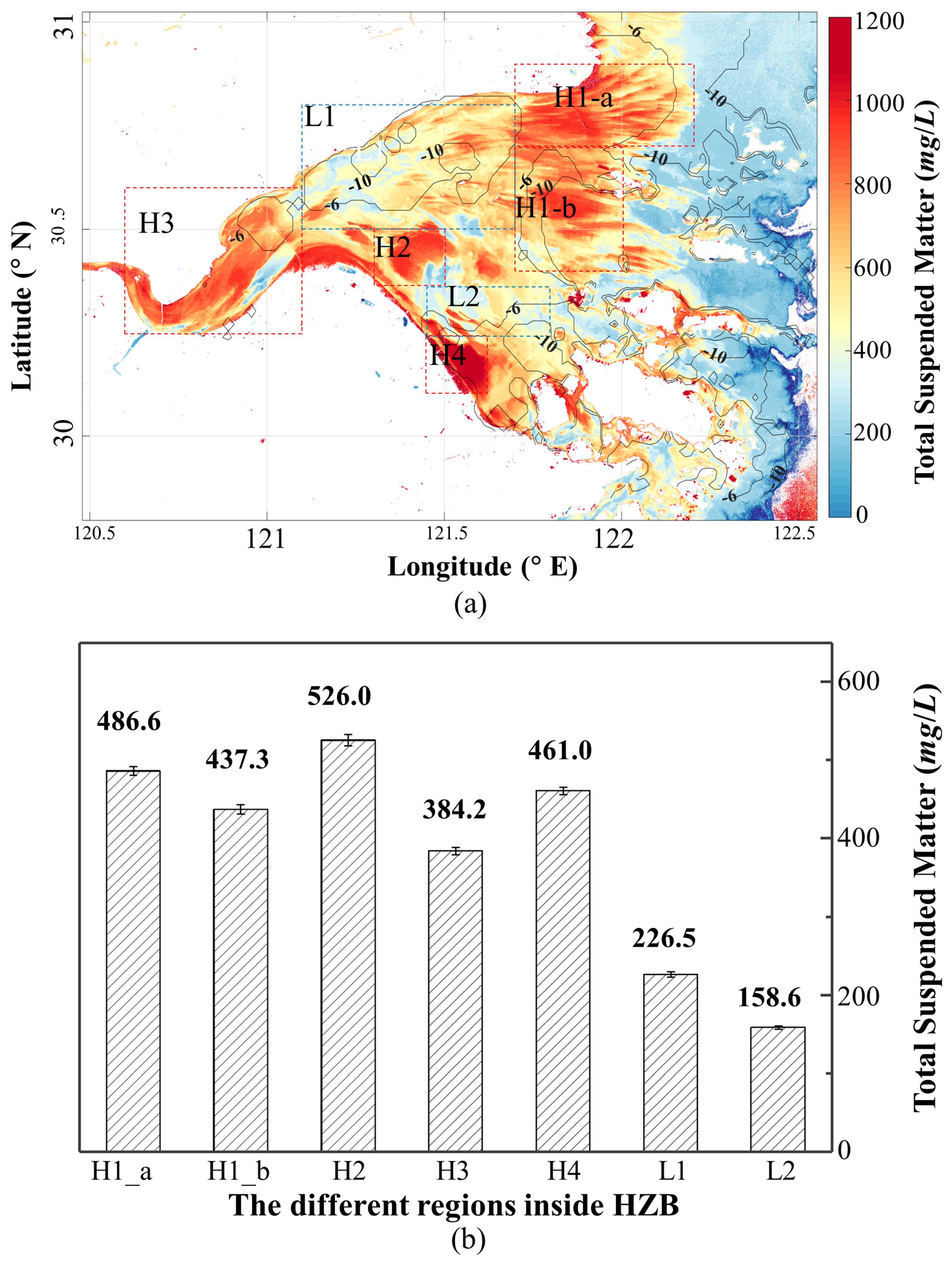
The TSM concentration inside HZB exhibited a “high–low–high” pattern from east to west, whereas it showed a slow decreasing trend at the mouth of HZB (Figure 4a). The average TSM concentration inside HZB ((371.8 ± 1.8) mg/L) was significantly higher than that at the mouth of HZB ((109.6 ± 3.0) mg/L), and there were four high TSM concentration zones and two low TSM concentration zones inside HZB at ebb tide, which was basically consistent with the results of previous studies [24,25]. Among them (Figure 4b), the high TSM concentration zone H1 was located in the area of the northeast coast of HZB and near the mouth of the bay, spanning 0.5° latitude and showing a feathery distribution along the coast. In the center of H1, there was a relatively narrow low concentration transition zone from east to west. The average TSM concentration in the north (H1_a) was (486.6 ± 2.8) mg/L, which was higher than that the (437.3 ± 3.1) mg/L in the south (H1_b), and the high TSM concentration area was bigger than that in the south. In addition, the other three high value zones were, respectively, distributed in the neck of the bay (H3) and the south bank area (H2, H4). At the neck of HZB, TSM was distributed in a strip along the northern shore of the bay, with an average TSM concentration of (384.2 ± 2.3) mg/L. The two high-value zones near the south bank were distributed in a cluster with an average TSM concentration of (526.0 ± 3.7) and (461.0 ± 2.6) mg/L, respectively. There was a large gradient at the edge of the high value zones. The low TSM concentration was concentrated in L1 and L2 zones. L1 was located on the northwest coast near the mouth of the bay, with an average TSM concentration of (226.5 ± 1.7) mg/L. L2 was distributed between Haihuangshan tide station and Zhoushan islands, with an average TSM concentration of (158.6 ± 1.1) mg/L.
Based on the tidal process and the topography of the bottom of HZB (Figure 4a), it was found that TSM concentration had a negative correlation with the topography within the water depth of 10 m at ebb tide. The average depth of HZB is 10 meters. Among them, the shallow water areas in the bay neck, the northeast coast near the bay mouth, and the south coast are generally less than five meters, corresponding to H3, H1a, H2, and H4 of the high TSM concentration areas, respectively. In addition, there is a deep-water tidal channel with a depth of 5–10 meters in the upper reaches of the north bank and the middle part of the south bank, respectively, corresponding to L1 and L2 in the low TSM concentration zones.

3.2. Minute Scale Dynamic Change Characteristics of TSM at Ebb Tide in HZB

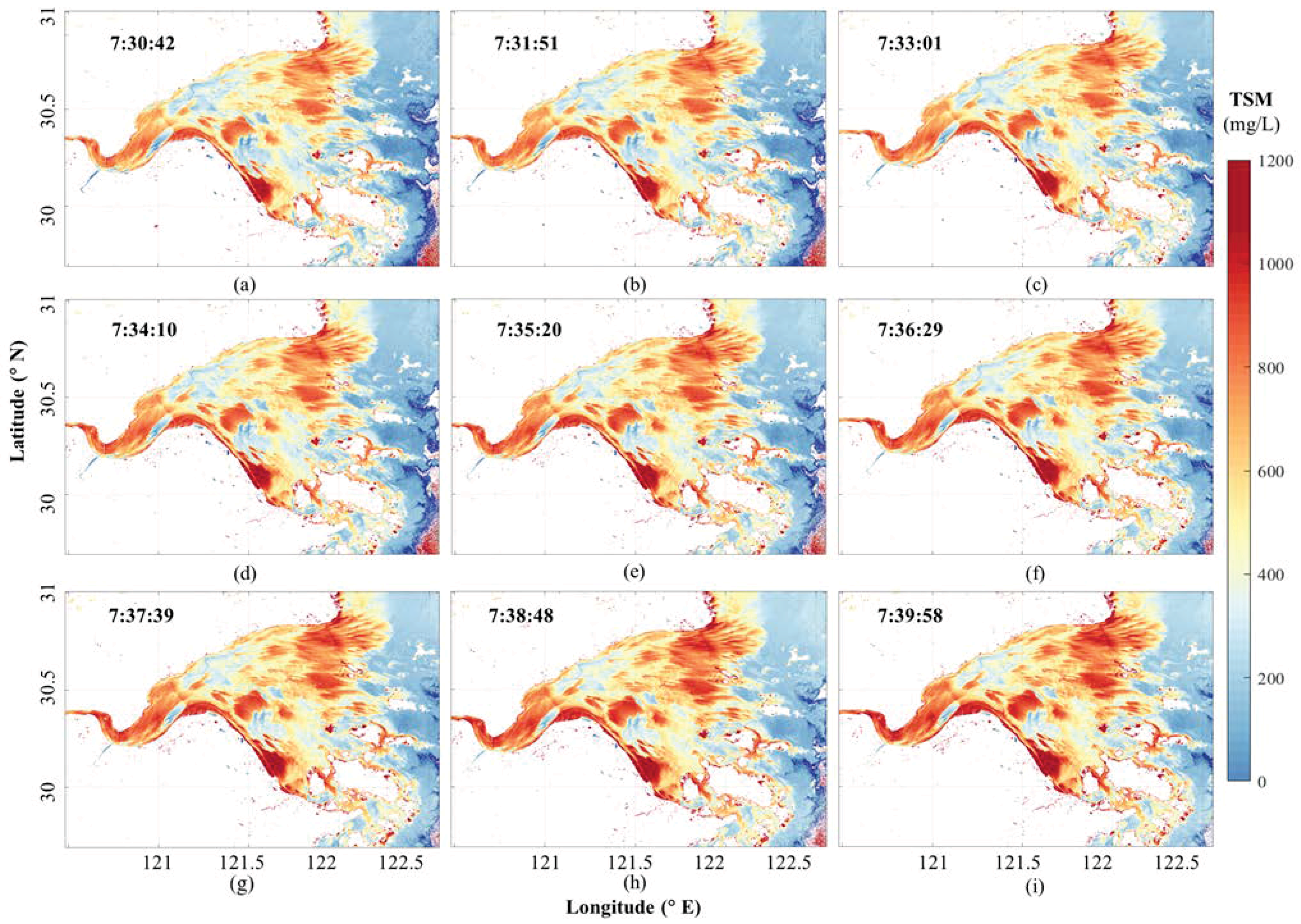
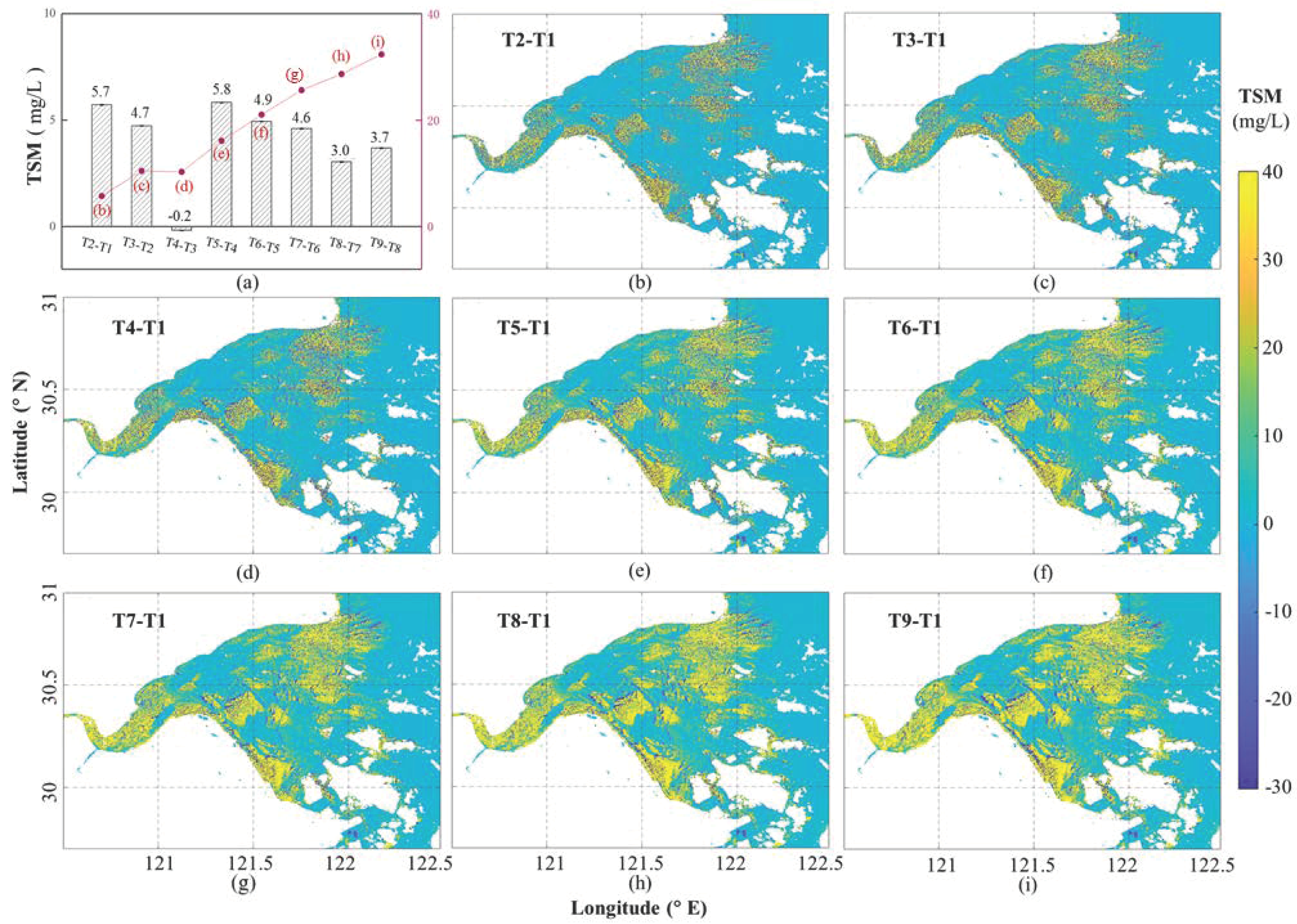
Based on the temporal and spatial variation of TSM concentration in minute scale (Figure 5 and Figure 6), it was found that TSM in HZB generally increases at ebb tide, and a more obvious increase was observed in the area with high TSM concentration. In the center of the low TSM concentration region, the concentration increased slightly. In order to quantitatively analyze the law of incremental change of TSM, linear regression analysis was performed on the average TSM concentration at ebb tide by taking the time interval as the independent variable and the TSM concentration as the dependent variable. According to the analysis results, TSM concentration showed a significant linear growth trend at ebb tide. The linear fitting formula was as Equation (6) (Figure 7a):
C T S M = 349.97 + 3.96 × Δ m i n u t e s ,
where the intercept is TSM concentration at the initial moment, and the slope coefficient represents the increment of TSM concentration per minute of about (3.96 ± 0.31) mg/L (the increment of TSM concentration per hour was (238 ± 19) mg/L). R2 is 0.99 and p < 0.01, indicating that the time variable could explain the 99% change in TSM concentration at ebb tide.
The in-situ TSM concentration at the four sampling stations during the 2010 cruise is shown in Figure 8. The location of the sampling station is shown in Figure 8a, and the TSM concentration variations of the four sampling stations are shown in Figure 8(b1–b4). The left axis of the graph represents tide level, and the right axis represents TSM concentration. The hourly TSM concentration increment at these four stations was calculated on average as the average increment per hour in HZB. The calculated result was (256 ± 12) mg/L, which was basically consistent with the GF-4 fitting results (the increment of TSM concentration per minute of about (3.96 ± 0.31) mg/L, that is, the increment of TSM concentration per hour was (238 ±19) mg/L).
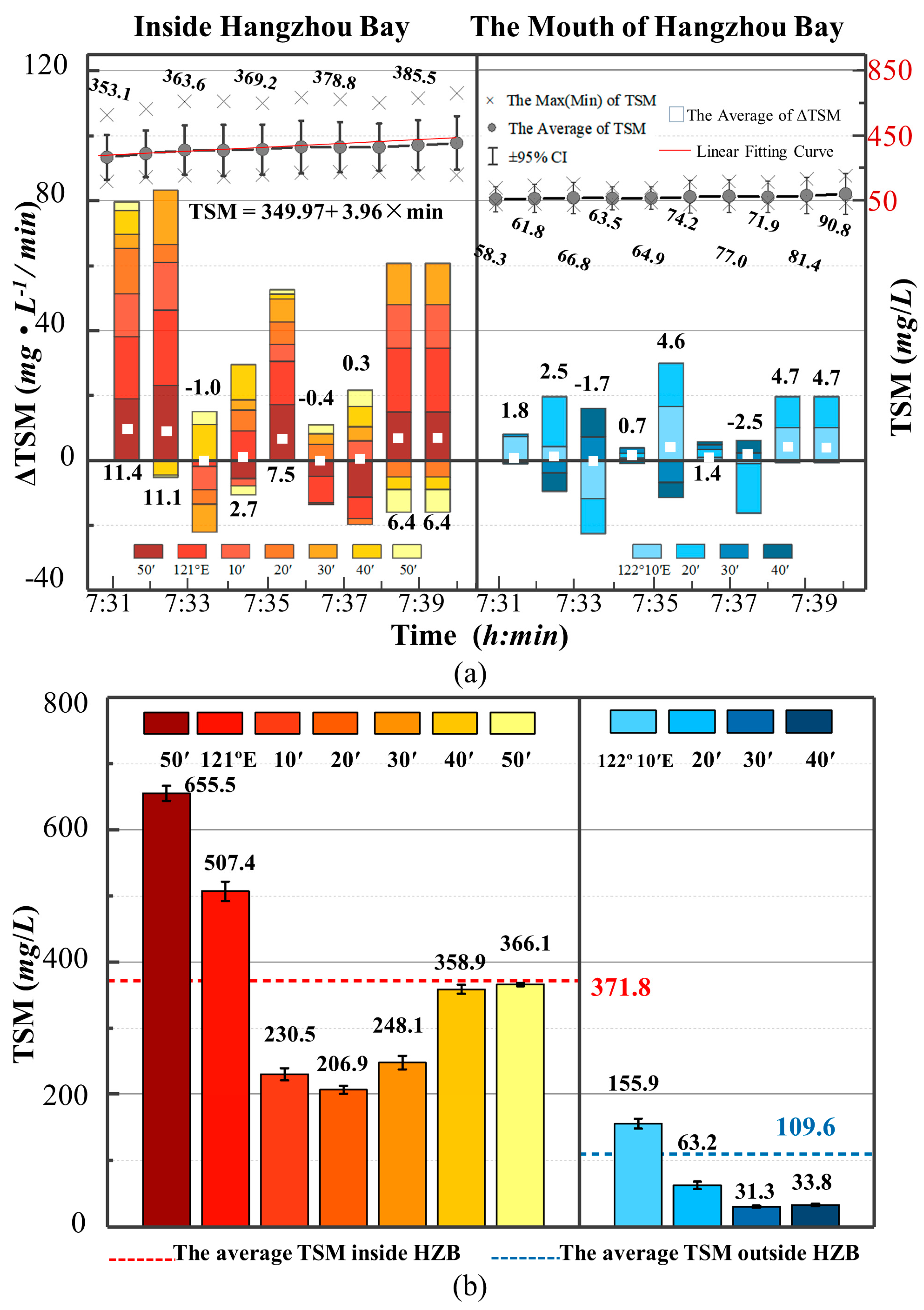
TSM concentration incremental histogram (Figure 7a) showed the contribution of different regions to the TSM concentration change in HZB. The left side of the Figure 7a is the situation inside HZB. The two transects at the neck of HZB (120°50′E, 121°E) accounted for the largest proportion (43%), that is, the increment of TSM concentration in these regions directly affected the increment of TSM concentration inside HZB. In addition, the average TSM concentration in these two regions ((655.5 ± 5.7) mg/L, (507.4 ± 7.4) mg/L) was significantly higher than the total average TSM concentration inside HZB ((371.8 ± 1.8) mg/L), indicating that the variation of TSM concentration in the high TSM concentration region played a dominant role in the variation of TSM concentration inside HZB (Figure 7b). However, the increment of the five transects (121°10′E, 121°20′E, 121°30′E, 121°40′E, and 121°50′E) across the deep-water tidal channel was relatively small, which made a small contribution to the increase of TSM concentration at ebb tide inside HZB. The right side of the Figure 7a was the TSM concentration variation outside HZB. The increment of TSM concentration showed little change. As the ebb tide continued, the TSM concentration difference between transects of the bay mouth gradually narrowed at the late ebb tide, and the average TSM concentration increased slightly, which was less than 5 mg/L.

4. Discussion

The distribution and variation of TSM are influenced by many factors, such as monsoon, freshwater input, tidal processes, and bottom topography [25,47]. In this study, during the remote sensing image acquisition period, there was no typhoon or other storm in the study area. According to the characteristic that the mean wind speed and mean freshwater input are basically unchanged within a small interval, the influence of wind speed and freshwater input on TSM within 10 min was ignored.
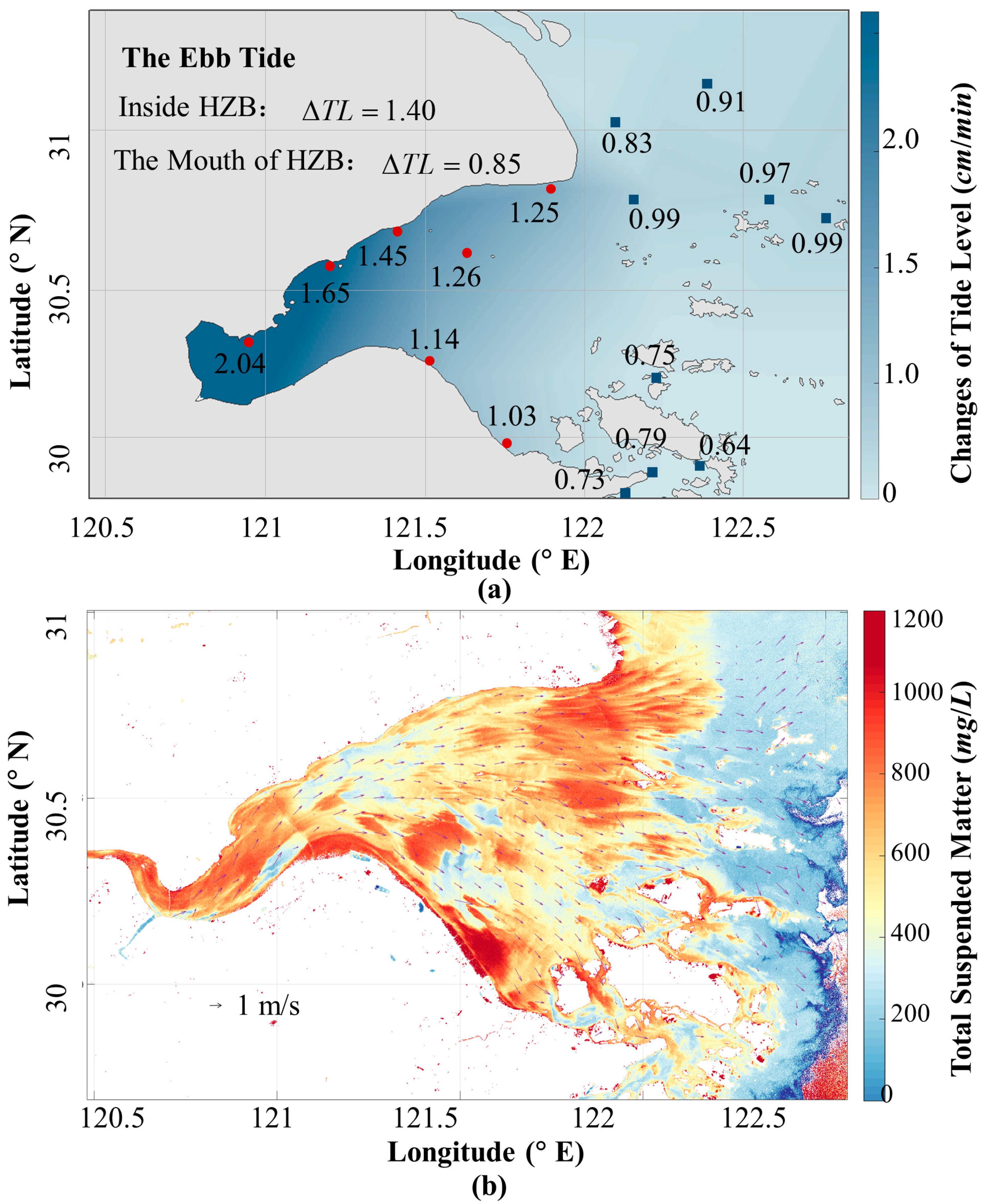
The tidal potential energy generated by the tidal range and the strong shear stress generated by the high current velocity both lead the sediment to be disturbed and re-suspended in the water, which may be the main reason for the increase of TSM concentration in HZB [5,23]. The greater the tidal range and the greater the potential energy of the tidal range, the greater the change of TSM concentration that will be caused [24]. Additionally, the higher velocity of current produces a strong shear on the seabed, which also makes the TSM concentration increase [23,48]. With the decrease of tidal range and current velocity, the re-suspension of sediment became weaker, and the TSM concentration decreased gradually. As shown in Figure 9, the variation of tide level and velocity were different at different locations in Hangzhou Bay. The change of tide levels inside HZB was mostly more than 1 cm/min, and the average change was about twice that of the mouth of the bay (Figure 9a). The maximum range of tide appears near Ganpu tide station at the bay neck (2.04 cm/min), which corresponded to the neck of HZB where TSM changed the most (mentioned in Section 3.2). The change of tide levels at the mouth of HZB was small, and the variation is mostly within the range of 0.5 to 1 cm/min. The TSM was also less variable in this water. This was consistent with the phenomenon mentioned above that the greater the tidal range, the greater the TSM concentration change. Similarly, the current velocity was the largest in the sea area near the Ganpu Tide Station and flew to the northeast and slowed down. This was also consistent with the phenomenon mentioned above that the greater the current velocity, the greater the TSM concentration change.
However, in the H1, H2, and H4 area, the lower tidal range and current velocity corresponded to higher TSM concentration, and in the L1 and L2 area, the higher tidal range and current velocity corresponded to lower TSM concentration. This phenomenon was contrary to the sediment lifting effect formed by higher tidal range and current velocity. The reason may be due to the difference of bottom topography, which affected the strength of the vertical sediment lifting action [4,49,50,51]. The tidal level changes in Luchaogang, Haihuangshan, and Zhenhai tide stations were small (tidal range < 1.25 cm/min). However, as they were located on the shallow tidal flats, the potential energy generated by the smaller tidal range was sufficient to reach the sediment, resulting in a greater stress on the sediment and a stronger resuspension process. Relative to the other three tide stations (Zhapu, Jinshanzui, and Tanhutide stations) inside HZB, the tide level changed significantly (tidal range > 1.25 cm/min). However, they were all located above the deep-water tidal channel on the north shore of HZB, the potential energy formed by the tidal range was consumed before reaching the seafloor, and the stress formed at the bottom was small and the resuspension process caused by it was weak. In addition, the two low TSM concentration zones L1 and L2 were located at the deep-water tidal channel where the current velocity was maximum. Although a strong sediment re-suspension process may result in an increase of TSM concentration near the seabed, the concentration of the whole water was still at a low TSM level, and as the velocity slowed down, these suspended particles were more likely to settle again. The current velocity of the H1_a, H2, and H4 concentration zones was small. However, due to the shoal location, the shear stress required for particulate re-suspension was relatively small. Therefore, the small flow velocity was sufficient to suspend the deposited particulate and caused TSM to increase. Zeng et al. [25] showed that the large sandbar and tidal flat where the TSM concentration high-value zone was located in HZB had more silt, and most of it was non-viscous fine sediment. Vertical stirring was more likely to cause the resuspension of sediment particles. Xie et al. [32] found that at the bottom of the two tidal channels in the north and south of HZB, there was a layer of viscous sediment with a thickness of about 10 m, which could be re-suspended with less sediments and a higher critical stress required for resuspension. The influence of different sediment types on vertical sand lifting also explained the phenomenon of higher tidal range and current velocity corresponding to lower TSM concentration and lower tidal range and current velocity corresponding to higher TSM concentration in HZB.
In recent years, the development and utilization of new clean energy such as tidal power have been paid more and more attention and become an important means to achieve sustainable development. The clarification of TSM minute scale variation in HZB is of great significance for understanding the complex hydrodynamic processes of strong tides and high turbidity sea areas as well as the physical and biogeochemical processes of the waters. In this paper, the variation trend and influencing factors of TSM minute scale in HZB were analyzed, and the relationship between TSM concentration variation and topography, tidal level, and current velocity was described in detail. It provided a more reliable reference for tidal prediction and disaster warning in strong tidal areas, and a reference for the selection of construction technology, equipment design, quality control, and safety assurance of marine engineering in strong tidal areas and other similar environments. However, in this paper, due to the lack of synchronous in-situ data, the accuracy of the TSM inversion algorithm still needs to be improved. In the analysis of the factors affecting TSM concentration, only qualitative analysis was carried out. With the further development of high spatial and temporal resolution satellite technology, the distribution characteristics and variation rules of TSM concentration at different scales can be studied in depth. It is an important direction of our current research to understand and master the smaller scale variation characteristics of TSM concentration and its dynamic mechanism.

5. Conclusions

Based on the study of remote sensing of TSM concentration in HZB using GF-4 satellite data and the analysis of TSM concentration variation, the following conclusions were drawn in this paper:
(1) The average TSM concentration in HZB was (371.8 ± 1.8) mg/L during the study period. There were four high TSM concentration zones and two low TSM concentration zones. The spatial distribution was affected by the bottom topography, and the high TSM zones were located on the tidal flat and bar with relatively shallow water depth, while the low TSM zones were located at the deep-water tidal channel.
(2) At ebb tide in HZB, TSM concentration showed a linear growth trend with an increase of about (3.96 ± 0.31) (mg/L)/minute. The concentration in the high TSM concentration area increased more obviously, and the variation of those high TSM concentration regions had a great influence on the TSM variation inside HZB. The concentration in the center of the low-TSM concentration regions increased slightly and contributed little to the variation of TSM.
(3) In HZB, the tidal process may be the main factor that affected TSM variation in a short time. The tidal potential energy generated by the tidal range and the strong shear stress generated by the high current velocity both lead to the re-suspension of the sedimentary particles and caused the concentration of TSM to increase. The bottom topography influenced the intensity of the tidal process and may be one of the reasons for TSM variation.

Author Contributions

Conceptualization: S.T. and Q.C.; methodology: S.T., Q.C. and J.W.; validation: Q.C., B.Z. and Z.Y.; formal analysis: S.T. and Q.C.; resources: S.T., B.Z. and Z.Y.; writing—original draft preparation: S.T. and Q.C.; writing—review and editing: S.T., Q.C., J.W., B.Z. and Z.Y.; funding acquisition: S.T. All authors have read and agreed to the published version of the manuscript.

Funding

This research was funded by the Chinese Academy of Sciences (Nos XDA19060501, ZDRW-XH-2019-2, and 133244KYSB20180029), the Guangdong Special Support Program (2019BT02H594), the Key Special Project for Introduced Talents Team of Southern Marine Science and Engineering Guangdong Laboratory (Guangzhou) (GML2019ZD0302) and the National Natural Science Foundation of China grant number 41876207.

Acknowledgments

The authors would like to thank the China Centre for Resources Satellite Data and Application and U.S. National Geophysical Data Center for providing GF-4 L1 products and topographic map data. They would also like to thank Fenfen Liu and Ruixi Zheng for their insightful comments and suggestions, which have greatly improved this article.

Conflicts of Interest

The authors declare no conflict of interest.

References

  1. Zeng, X.; He, R.; Xue, Z.; Wang, H.; Wang, Y.; Yao, Z.; Guan, W.; Warrillow, J. River-derived sediment suspension and transport in the Bohai, Yellow, and East China Seas: A preliminary modeling study. Cont. Shelf Res. 2015, 111, 112–125. [Google Scholar] [CrossRef] [Green Version]
  2. Ziegler, C.K.; Lick, W. The transport of fine-grained sediments in shallow waters. Environ. Geol. Water Sci. 1988, 11, 123–132. [Google Scholar] [CrossRef]
  3. Yu, Q.; Wang, Y.P.; Flemming, B.; Gao, S. Tide-induced suspended sediment transport: Depth-averaged concentrations and horizontal residual fluxes. Cont. Shelf Res. 2012, 34, 53–63. [Google Scholar] [CrossRef]
  4. Xiong, J.; Wang, X.H.; Wang, Y.P.; Chen, J.; Shi, B.; Gao, J.; Yang, Y.; Yu, Q.; Li, M.; Yang, L.; et al. Mechanisms of maintaining high suspended sediment concentration over tide-dominated offshore shoals in the southern Yellow Sea. Estuar. Coast Shelf Sci. 2017, 191, 221–233. [Google Scholar] [CrossRef]
  5. Li, J.; Gao, S.; Wang, Y. Delineating suspended sediment concentration patterns in surface waters of the Changjiang Estuary by remote sensing analysis. Acta Oceanol. Sin. 2010, 29, 38–47. [Google Scholar] [CrossRef]
  6. Abascal-Zorrilla, N.; Vantrepotte, V.; Huybrechts, N.; Ngoc, D.D.; Anthony, E.J.; Gardel, A. Dynamics of the Estuarine Turbidity Maximum Zone from Landsat-8 Data: The Case of the Maroni River Estuary, French Guiana. Remote Sens. 2020, 12, 2173. [Google Scholar] [CrossRef]
  7. Xu, X.; Chen, J.; Ye, X. Study on the seasonal migration of surface suspended sediment in the Taiwan Strait based on remote sensing. In Remote Sensing of the Ocean, Sea Ice, Coastal Waters, and Large Water Regions 2015; Bostater, C.R., Mertikas, S.P., Neyt, X., Eds.; Curran Associates, Inc.: Red Hook, NY, USA, 2015; Volume 9638. [Google Scholar]
  8. Burenkov, V.I.; Vazyulya, S.V.; Kopelevich, O.V.; Sheberstov, S.V. Spatiotemporal variability of the suspended matter distribution in the surface layer of the white sea from the data of the SeaWiFS satellite color scanner. Oceanology 2004, 44, 472–480. [Google Scholar]
  9. Bai, Y.; He, X.; Pan, D.; Zhu, Q.; Lei, H.; Tao, B.; Hao, Z. The extremely high concentration of suspended particulate matter in Changjiang Estuary detected by MERIS data. In Remote Sensing of the Coastal Ocean, Land, and Atmosphere Environment; Frouin, R.J., Yoo, H.R., Won, J.S., Feng, A., Eds.; Curran Associates, Inc.: Red Hook, NY, USA, 2010; Volume 7858. [Google Scholar]
  10. Shen, F.; Verhoef, W.; Zhou, Y.; Salama, M.S.; Liu, X. Satellite Estimates of Wide-Range Suspended Sediment Concentrations in Changjiang (Yangtze) Estuary Using MERIS Data. Estuaries Coasts 2010, 33, 1420–1429. [Google Scholar] [CrossRef]
  11. Li, P.; Ke, Y.; Bai, J.; Zhang, S.; Chen, M.; Zhou, D. Spatiotemporal dynamics of suspended particulate matter in the Yellow River Estuary, China during the past two decades based on time-series Landsat and Sentinel-2 data. Mar. Pollut. Bull. 2019, 149. [Google Scholar] [CrossRef]
  12. Scanes, P.; Coade, G.; Doherty, M.; Hill, R. Evaluation of the utility of water quality based indicators of estuarine lagoon condition in NSW, Australia. Estuar. Coast. Shelf Sci. 2007, 74, 306–319. [Google Scholar] [CrossRef]
  13. Wang, F.; Zhou, B.; Liu, X.; Zhou, G.; Zhao, K. Remote-sensing inversion model of surface water suspended sediment concentration based on in situ measured spectrum in Hangzhou Bay, China. Environ. Earth Sci. 2012, 67, 1669–1677. [Google Scholar] [CrossRef]
  14. Gordon, H.R.; Wang, M. Retrieval of water-leaving radiance and aerosol optical thickness over the oceans with SeaWiFS: A preliminary algorithm. Appl Opt. 1994, 33, 443–452. [Google Scholar] [CrossRef] [PubMed]
  15. Gao, F.; Wang, Y.P.; Zhang, Y.Z. Evaluation of the Crosta method for the retrieval of water quality parameters from remote sensing data in the Pearl River estuary. Water Qual. Res. J. Can. 2020, 5, 209–220. [Google Scholar] [CrossRef]
  16. Mayo, M.; Karnieli, A.; Gitelson, A.; Benavraham, Z. Determination of suspended sediment concentrations from CZCS data. Photogramm. Eng. Remote Sens. 1993, 59, 1265–1269. [Google Scholar]
  17. Burenkov, V.I.; Ershova, S.V.; Kopelevich, O.V.; Sheberstov, S.V.; Shevchenko, V.P. An estimate of the distribution of suspended matter in the Barents Sea waters on the basis of the SeaWiFS satellite ocean color scanner. Oceanology 2001, 41, 622–628. [Google Scholar]
  18. Tian, L.; Wai, O.W.H.; Chen, X.; Li, W.; Li, J.; Li, W.; Zhang, H. Retrieval of total suspended matter concentration from Gaofen-1 Wide Field Imager (WFI) multispectral imagery with the assistance of Terra MODIS in turbid water-case in Deep Bay. Int. J. Remote Sens. 2016, 37, 3400–3413. [Google Scholar] [CrossRef]
  19. Wang, F.; Zhou, B.; Xu, J.; Song, L.; Wang, X. Application of neural network and MODIS 250 m imagery for estimating suspended sediments concentration in Hangzhou Bay, China. Environ. Geol. 2009, 56, 1093–1101. [Google Scholar] [CrossRef]
  20. Tang, S.L.; Larouche, P.; Niemi, A.; Michel, C. Regional algorithms for remote-sensing estimates of total suspended matter in the Beaufort Sea. Int. J. Remote Sens. 2013, 34, 6562–6576. [Google Scholar] [CrossRef]
  21. Toming, K.; Kutser, T.; Uiboupin, R.; Arikas, A.; Vahter, K.; Paavel, B. Mapping Water Quality Parameters with Sentinel-3 Ocean and Land Colour Instrument Imagery in the Baltic Sea. Remote Sens. 2017, 9, 1070. [Google Scholar] [CrossRef] [Green Version]
  22. Chami, M.; Larnicol, M.; Migeon, S.; Minghelli, A.; Mathieu, S. Potential for nocturnal satellite detection of suspended matter concentrations in coastal waters using a panchromatic band: A feasibility study based on VIIRS (NASA/NOAA) spectral and radiometric specifications. Opt. Express 2020, 28, 15314–15330. [Google Scholar] [CrossRef]
  23. He, X.; Bai, Y.; Pan, D.; Huang, N.; Dong, X.; Chen, J.; Chen, C.-T.A.; Cui, Q. Using geostationary satellite ocean color data to map the diurnal dynamics of suspended particulate matter in coastal waters. Remote Sens. Environ. 2013, 133, 225–239. [Google Scholar] [CrossRef]
  24. Hu, Y.; Yu, Z.; Zhou, B.; Li, Y.; Yin, S.; He, X.; Peng, X.; Shum, C.K. Tidal-driven variation of suspended sediment in Hangzhou Bay based on GOCI data. Int. J. Appl. Earth Obs. Geoinf. 2019, 82. [Google Scholar] [CrossRef]
  25. Liu, J.; Liu, J.; He, X.; Pan, D.; Bai, Y.; Zhu, F.; Chen, T.; Wang, Y. Diurnal Dynamics and Seasonal Variations of Total Suspended Particulate Matter in Highly Turbid Hangzhou Bay Waters Based on the Geostationary Ocean Color Imager. IEEE J. Sel. Top. Appl. Earth Obs. Remote Sens. 2018, 11, 2170–2180. [Google Scholar] [CrossRef]
  26. Cheng, Z.; Wang, X.H.; Paull, D.; Gao, J. Application of the Geostationary Ocean Color Imager to Mapping the Diurnal and Seasonal Variability of Surface Suspended Matter in a Macro-Tidal Estuary. Remote Sens. 2016, 8, 244. [Google Scholar] [CrossRef] [Green Version]
  27. Pan, Y.; Shen, F.; Wei, X. Fusion of Landsat-8/OLI and GOCI Data for Hourly Mapping of Suspended Particulate Matter at High Spatial Resolution: A Case Study in the Yangtze (Changjiang) Estuary. Remote Sens. 2018, 10, 158. [Google Scholar] [CrossRef] [Green Version]
  28. Li, F.; Fu, J.; Xin, L.; Liu, Y.; Liu, Z. New developments in super-resolution for GaoFen-4. In Image and Signal Processing for Remote Sensing XXIII; Bruzzone, L., Bovolo, F., Eds.; Curran Associates, Inc.: Red Hook, NY, USA, 2017; Volume 10427. [Google Scholar]
  29. Wang, D.; He, H. Observation Capability and Application Prospect of GF-4 Satellite. In 3rd International Symposium of Space Optical Instruments and Applications; Urbach, H.P., Zhang, G., Eds.; Springer Nature: Berlin, Germany, 2017; Volume 192, pp. 393–401. [Google Scholar]
  30. Li, F.; Xin, L.; Guo, Y.; Gao, D.; Kong, X.; Jia, X. Super-Resolution for GaoFen-4 Remote Sensing Images. IEEE Geosci. Remote Sens. Lett. 2018, 15, 28–32. [Google Scholar] [CrossRef]
  31. Guo, Y.; Zhang, J.; Zhang, L.; Shen, Y. Computational investigation of typhoon-induced storm surge in Hangzhou Bay, China. Estuar. Coast. Shelf Sci. 2009, 85, 530–536. [Google Scholar] [CrossRef]
  32. Xie, D.; Wang, Z.; Gao, S.; De Vriend, H.J. Modeling the tidal channel morphodynamics in a macro-tidal embayment, Hangzhou Bay, China. Cont. Shelf Res. 2009, 29, 1757–1767. [Google Scholar] [CrossRef]
  33. Lin, C.-M.; Zhuo, H.-C.; Gao, S. Sedimentary facies and evolution in the Qiantang River incised valley, eastern China. Mar. Geol. 2005, 219, 235–259. [Google Scholar] [CrossRef]
  34. Amante, C.; Eakins, B.W. ETOPO1 1 Arc-Minute Global Relief Model: Procedures, Data Sources and Analysis. NOAA Technical Memorandum NESDIS NGDC-24; National Geophysical Data Center, NOAA: Boulder, CO, USA, 2009.
  35. Normalized Multi-band Drought Index Center. Tide Tables 2020; China Ocean Press: Beijing, China, 2020; Volume 3. [Google Scholar]
  36. Goyens, C.; Jamet, C.; Ruddick, K.G. Spectral relationships for atmospheric correction. II. Improving NASA’s standard and MUMM near infra-red modeling schemes. Opt. Express 2013, 21, 21176–21187. [Google Scholar] [CrossRef] [Green Version]
  37. Lavender, S.J.; Pinkerton, M.H.; Moore, G.F.; Aiken, J.; Blondeau-Patissier, D. Modification to the atmospheric correction of SeaWiFS ocean colour images over turbid waters. Cont. Shelf Res. 2005, 25, 539–555. [Google Scholar] [CrossRef]
  38. Wang, M.H.; Shi, W. The NIR-SWIR combined atmospheric correction approach for MODIS ocean color data processing. Opt. Express 2007, 15, 15722–15733. [Google Scholar] [CrossRef] [PubMed] [Green Version]
  39. He, Q.J.; Chen, C.Q. A new approach for atmospheric correction of MODIS imagery in turbid coastal waters: A case study for the Pearl River Estuary. Remote Sens. Lett. 2014, 5, 249–257. [Google Scholar] [CrossRef]
  40. Ye, H.B.; Chen, C.Q.; Yang, C.Y. Atmospheric Correction of Landsat-8/OLI Imagery in Turbid Estuarine Waters: A Case Study for the Pearl River Estuary. IEEE J. Stars 2017, 10, 252–261. [Google Scholar] [CrossRef]
  41. Wu, J.; Chen, C.Q.; Nukapothula, S. Atmospheric Correction of GOCI Using Quasi-Synchronous VIIRS Data in Highly Turbid Coastal Waters. Remote Sens. 2020, 12, 89. [Google Scholar] [CrossRef] [Green Version]
  42. Vermote, E.F.; Tanre, D.; Deuze, J.L.; Herman, M.; Morcrette, J.J. Second Simulation of the Satellite Signal in the Solar Spectrum, 6S: An overview. IEEE Trans. Geosci. Remote Sens. 1997, 35, 675–686. [Google Scholar] [CrossRef] [Green Version]
  43. Ahmad, Z.; Franz, B.A.; McClain, C.R.; Kwiatkowska, E.J.; Werdell, J.; Shettle, E.P.; Holben, B.N. New aerosol models for the retrieval of aerosol optical thickness and normalized water-leaving radiances from the SeaWiFS and MODIS sensors over coastal regions and open oceans. Appl. Opt. 2010, 49, 5545–5560. [Google Scholar] [CrossRef]
  44. Yang, H.; Arnone, R.; Jolliff, J. Estimating advective near-surface currents from ocean color satellite images. Remote Sens. Environ. 2015, 158, 1–14. [Google Scholar] [CrossRef]
  45. Emery, W.J.; Fowler, C.; Clayson, C.A. Satellite-image derived gulf-stream currents compared with numerical-model RESULTS. J. Atmosheric Ocean. Technol. 1992, 9, 286–304. [Google Scholar] [CrossRef] [Green Version]
  46. Crocker, R.I.; Matthews, D.K.; Emery, W.J.; Baldwin, D.G. Computing coastal ocean surface currents from infrared and ocean color satellite imagery. IEEE Trans. Geosci. Remote Sens. 2007, 45, 435–447. [Google Scholar] [CrossRef]
  47. Wang, Z.; Li, L.; Chen, D.; Xu, K.; Wei, T.; Gao, J.; Zhao, Y.; Chen, Z.; Masabate, W. Plume front and suspended sediment dispersal off the Yangtze (Changjiang) River mouth, China during non-flood season. Estuar. Coast. Shelf Sci. 2007, 71, 60–67. [Google Scholar] [CrossRef]
  48. Chen, S.-L.; Zhang, G.-A.; Yang, S.-L.; Shi, J.Z. Temporal variations of fine suspended sediment concentration in the Changjiang River estuary and adjacent coastal waters, China. J. Hydrol. 2006, 331, 137–145. [Google Scholar] [CrossRef]
  49. Cai, L.; Tang, D.; Li, X.; Zheng, H.; Shao, W. Remote sensing of spatial-temporal distribution of suspended sediment and analysis of related environmental factors in Hangzhou Bay, China. Remote Sens. Lett. 2015, 6, 597–603. [Google Scholar] [CrossRef]
  50. Ralston, D.K.; Geyer, W.R.; Warner, J.C. Bathymetric controls on sediment transport in the Hudson River estuary: Lateral asymmetry and frontal trapping. J. Geophys. Res. Ocean. 2012, 117. [Google Scholar] [CrossRef] [Green Version]
  51. Normandin, C.; Lubac, B.; Sottolichio, A.; Frappart, F.; Ygorra, B.; Marieu, V. Analysis of suspended sediment variability in a large highly turbid estuary using a 5-year-long remotely sensed data archive at high resolution. J. Geophys. Res. Ocean. 2019, 124, 7661–7682. [Google Scholar] [CrossRef] [Green Version]
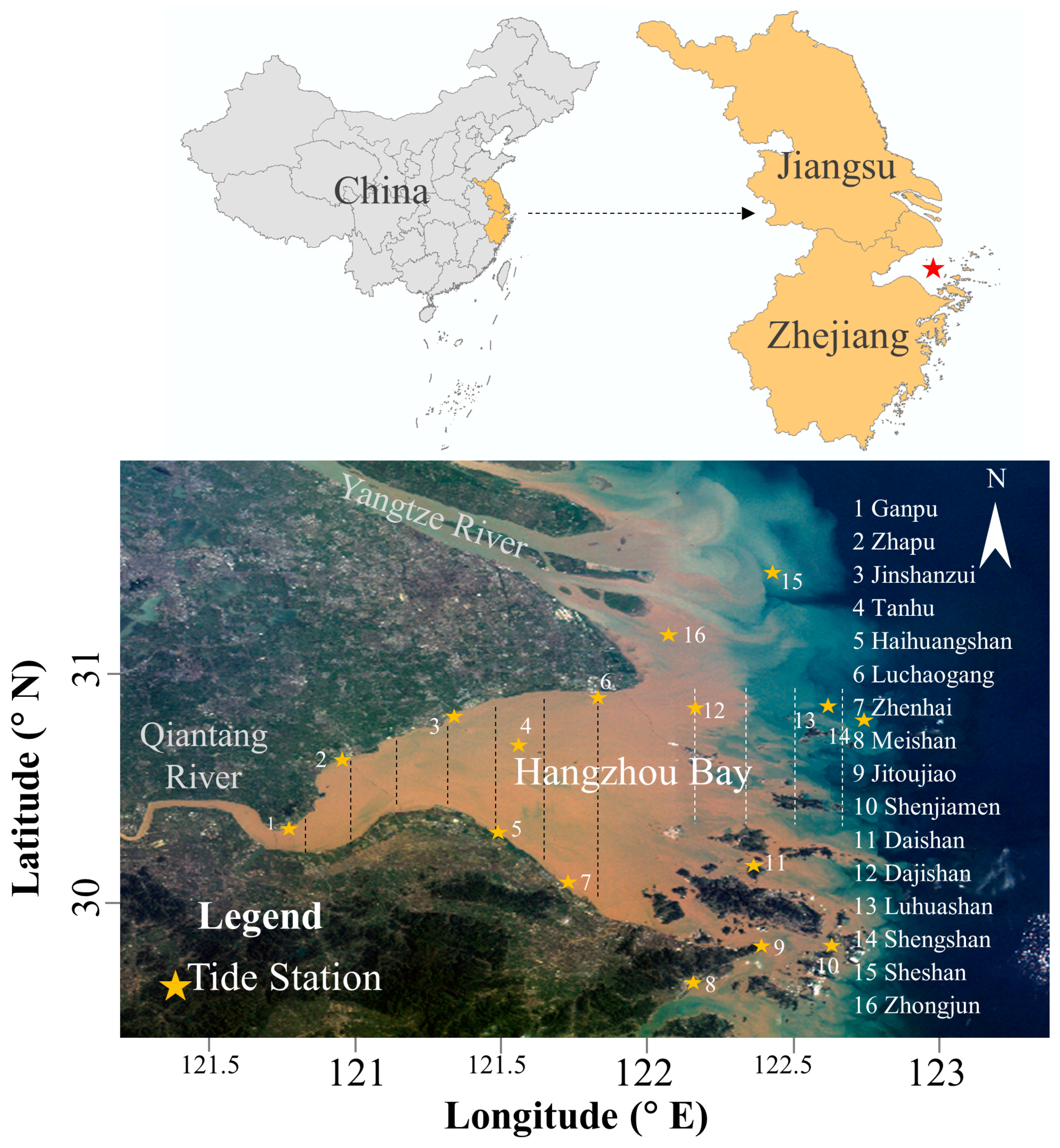
Figure 1. The HZB and its adjacent areas shown in the GF-4 L1 true color composite image collected at 7:30:42 on 28 August 2017. The tide station for tide level data is indicated with a yellow pentacle. The black and white dotted lines are chosen to represent transects inside and outside HZB, respectively; concentration was then calculated along transects.
Remotesensing 13 01339 g001
Figure 2. (ac) The Rrs comparisons of equivalent bands between the GOCI and GF-4 based on the in-situ data. The black dotted lines show the 1:1 relationship, and the red solid line represents the linear regression result.
Remotesensing 13 01339 g002
Figure 4. The spatial distribution of mean TSM concentration during the study period in HZB. (a) The bathymetry contours of HZB shown in the TSM concentration distribution image. (b) The mean TSM concentration of different regions inside HZB, including four high TSM concentration zones and two low TSM concentration zones (H1_a from 121.70 to 122.20° E and 30.70 to 30.90° N, H1_b from 121.70 to 122.00° E and 30.40 to 30.70° N, H2 from 121.30 to 121.50° E and 30.35 to 30.50° N, H3 from 120.60 to 121.10° E and 30.25 to 30.60° N, H4 from 121.45 to 121.60° E and 30.10 to 30.25° N, L1 from 121.10 to 121.70° E and 30.50 to 30.80° N, and L2 from 121.45 to 121.70° E and 30.25 to 30.35° N).
Remotesensing 13 01339 g004
Figure 5. (ai) The per minute spatial distribution of TSM concentration in HZB retrieved by the GF-4 on 28 August 2017. The labeled time in the image corresponds to the observation time in Beijing time.
Remotesensing 13 01339 g005
Figure 6. The minute variations of TSM concentration in HZB. (a) The bar shows the average TSM concentration difference per minute, and the red dotted line shows the cumulative average TSM concentration difference per minute. (bi) shows the spatial distribution of the cumulative average TSM concentration difference per minute.
Remotesensing 13 01339 g006
Figure 7. (a) The increment of TSM in minute scale. The left side is the situation inside HZB, and the right-hand side is outside HZB. The box-whisker plot is the average TSM per minute. The histogram plot is the TSM change between two box-whisker plots, which is a superposition of the TSM change in different transects. The white small rectangle represents the average change of TSM, and the value is marked under the histogram plot. (b) The mean TSM concentration at different transects in HZB, including seven transects inside HZB and four transects outside HZB. The red and blue dotted lines are chosen to represent the average TSM concentration inside and outside HZB, respectively.
Remotesensing 13 01339 g007
Figure 8. The hourly variation of TSM concentration measured at ebb tide in the HZB. (a) The locations of in-situ sampling stations for TSM concentration during the 2011 cruise are indicated with a red triangle, and the hourly variations of TSM concentration with red dot lines at the station (b1) on 2 December 2011, the station (b2) on 3 December 2011, the station (b3) on December 4, 2011, and the station (b4) on 9 December 2011.
Remotesensing 13 01339 g008
Figure 9. (a) The minute scale variation of tide levels at different tide stations at ebb tide. The red points represent the location of tide stations inside HZB, and the blue squares represent the location of the tide station outside HZB. (b) The average velocity of current within 10 min at ebb tide in HZB, which is calculated by TSM.
Remotesensing 13 01339 g009
Table 1. The list of symbols and abbreviation definitions.
SymbolDescriptionUnit
M2One of the semi-diurnal tidal constituents, the relative amplitude is 100 cm and the period is 12.4206 h.-
RrsAbove-surface remote sensing reflectance.1/Sr
dThe Sun–Earth distance at the time of the measurement showing the relative deviation from the average Sun–Earth distance d0 equal to 1 AU.AU
LλThe TOA radiance measured by the sensor in band λ.W/m2/Sr/μm
θsSolar zenith angles.rad
F0The extraterrestrial solar irradiance for mean Sun–Earth distance d0.W/ m2/μm
RrThe reflectance of Rayleigh scattering.1/Sr
RaThe reflectance of aerosol multiple scattering reflectance.1/Sr
tvThe diffuse transmittance of the atmospheric column.-
SAIThe spectral absorption index, one of the absorption-band parameters.-
CTSMThe total suspended matter concentration.mg/L
sThe symmetry of the spectral absorption band used for calculation of the SAI index.-
RMSERoot mean square error.-
rCorrelation coefficient.-
ΔTSMThe difference of TSM concentration.mg/L
Table 2. The comparison of bands between GOCI and GF-4 satellites.
SensorParameterSpectral Band
(nm)
Resolution
(m)
GOCIBand name B1B2B3B4B5B6B7B8
Spectral range 402~422433~453480~500545~565650~670675~685735~755845~885 500
Central wavelength (412)(443)(490) *(555) *(660)(680)(745) *(865)
GF-4Band nameB1 B2B3B4 B5 B6
Spectral range450~900 450~520520~600630~690 760~900 3500~410050
Central wavelength- (519) *(550) *(628) (770) * -
* Those bands were used in the SAI algorithm.
Publisher’s Note: MDPI stays neutral with regard to jurisdictional claims in published maps and institutional affiliations.