Abstract
As pre-launch antenna calibrations are not available for GPS and GLONASS satellites, the high correlation between the terrestrial scale and phase center offset (PCO) prevents a reliable estimation of the terrestrial scale with GNSS (Global Navigation Satellite System) technology. Fortunately, the ground calibrated PCO values for Galileo, BeiDou navigation satellite system (BDS), and QZSS have been released, making a reliable estimation of the terrestrial scale with GNSS possible. In the third reprocess (repro3) of International GNSS Service (IGS), the terrestrial scale derived with Galileo, has been used. To evaluate the consistency of the terrestrial scale derived from the BDS-released PCOs as well as Galileo-released ones, and to incorporate BDS into IGS repro3 as well as operational legacy analysis, the phase center variations (PCV) and PCO for BDS medium earth orbit (MEO) and inclined geostationary orbit (IGSO) satellites are estimated to be consistent with GPS/GLONASS antenna offsets in two frames, i.e., IGb14 and IGS R3, considering robot calibrations of the ground receiver antenna models for BDS released by Geo++. We observe that the average offset of Z-PCOs achieves +98.8 mm between BDS official released and the estimated PCOs in IGb14 frame for BDS-3 MEO satellites, whereas the average offset for Z-PCO is about +174.1 mm (about −1.27 ppb at the height of BDS MEO satellites) between the solutions in IGSR3 and IGb14 frame. The phase center solutions are evaluated with orbit boundary disclosures (OBD) as well as the global station coordinates. The orbit consistency benefits from the PCO/PCV estimates, particularly for BDS-2 MEO satellites, of which the 3D RMS (root mean square) OBD is reduced by 50%, whereas 3D OBD achieves about 90.0 mm for BDS-3 MEO satellites. Moreover, the scale bias between BDS-derived station coordinates and IGS legacy solutions in IGb14 frame is reduced from +0.446 ± 0.153 ppb to +0.012 ± 0.112 ppb using PCO/PCV estimates in IGb14, instead of the BDS official released values. Additionally, the residuals of the BDS-derived station heights (after the Helmert transformation) are slightly reduced from 9.65 to 8.62 mm. On the other hand, about +0.226 ± 0.175 ppb is observed between BDS-only coordinate solutions derived from PCO/PCV estimates in IGSR3 frame and the IGS repro3 initial combination. These results demonstrate that the scale inconsistency derived from BDS and Galileo released PCOs is about +1.854 ± 0.191 ppb, and a good consistency of PCO/PCC estimates for BDS in IGb14 and IGSR3 frame with other systems of GPS/ GLONASS antenna offsets is achieved.
1. Introduction
With the launch of the last satellite on 23 June 2020, Chinese BeiDou navigation satellite system (BDS) completed its construction and was officially announced to provide global position, navigation, and timing (PNT) services. Until 2 December 2020, there have been 49 satellites distributed in geosynchronous orbit (GEO), inclined geostationary orbit (IGSO), and medium earth orbit (MEO) [1]. To analyze all available Global Navigation Satellite System (GNSS) signals by preparing the International GNSS Service (IGS) for multi-GNSS data processing, the pilot project named as the multi-GNSS experiment (MGEX) was initiated in 2012 [2]. As a backbone of the MGEX project, a new network of multi-GNSS monitoring stations has been deployed around the globe. With the observations collected by MGEX and other tracking networks, several analysis centers (ACs), e.g., the Center for Orbit Determination in Europe (CODE, Bern, Switzerland), German Research Center for Geosciences (GFZ, Potsdam, German), and Wuhan University (WHU, Wuhan, China), have provided the precise ephemeris, clock, and biases products for BDS satellites. The experimental combination indicates that the BDS orbit consistency between the contributing ACs has reached a level of more than several decimeters to meters for GEO and IGSO, and several centimeters for MEO satellites [3].
Besides the dynamic model, the consistent measurement models, particularly phase center corrections (PCCs), used in data processing are essential for more consistency of GPS and GLONASS orbits as shown by Schmid et al. [4] and Dilssner et al. [5]. GNSS observations measure the geometric distance between the antenna phase center locations of the navigation satellite at signal emission time and the receiving antenna at signal reception time. The phase center locations are usually different from the mechanical antenna reference points (ARP) which are used for GNSS observation modeling. Because of this difference, high-precision GNSS applications require a set of PCCs to tie the GNSS measurements consistently to the ARP of the satellite and receiver antenna. Normally, the set of PCCs for the antenna phase center consists of the phase center offset (PCO) and phase center variation (PCV). PCO of satellite antenna is a vector which defines the position of the “mean antenna phase center” with respect to the center of mass (CoM), which is the ARP of the satellite [6]. PCV is a consistent function which models the locations of actual antenna phase centers with respect to the “mean antenna phase center” depending on the observation direction. For signal transmitting antennas, although its PCC could be estimated from global GNSS tracking data, due to high mathematical correlations between the station heights, tropospheric delays, and PCC of receiver antenna, it is not possible to obtain reasonable solutions without making two fundamental assumptions [7,8,9]: (1) absolute antenna PCCs for the receiving antennas have to be introduced as known, and (2) the scale of the terrestrial network has to be fixed with respect to a particular terrestrial reference frame. For the first assumption, prior to 6 November 2006, the relative PCCs were used for receiver antenna. However, using relative calibrations in global networks yields systematic effects. Hence, the absolute antenna calibration approaches have been developed for the estimation of the PCO and PCV of receiving antenna [10]. With the reprocess of GNSS data, IGS has provided an official absolute antenna model with PCOs and PCVs for both GPS and GLONASS satellites in ATX file, e.g., igs14_WWWW.atx (WWWW represents the GPS week hereafter) consistent with IGb14 frame. For upcoming GNSS systems, e.g., Galileo and BDS, the PCOs and PCVs from officially released metadata are recommended by IGS currently without investigating the consistency with GPS and GLONASS antenna offsets as well as the terrestrial scale.
To keep the consistency between upcoming GNSS constellations and the established ones, the PCOs and PCVs were estimated for Galileo in IGS14 frame [7], and for BDS in IGS08 frame [11,12,13,14] by modeling the receiver antenna PCCs with that of GPS L1 and L2, as no ground calibrations were available for the new GNSS satellites at that time. In 2017, the European GNSS Agency (ESA) released the pre-launch calibrated PCOs and PCVs for Galileo satellites [15]. Moreover, the new receiver antenna models covering all GNSS frequencies, based on robot calibrations, were available when IGS prepared for the third reprocess. Hence, it provides an essential chance to evaluate whether GNSS global network solutions qualify to contribute to the scale determination of terrestrial networks [16]. Additionally, it is well known that the fundamental issue concerning the determination of the terrestrial scale with GNSS is that there is a high correlation between the terrestrial scale, the satellite PCOs in Z component (Z-PCOs), the zenith wet delays, and the station as well as satellite clock offsets. Since pre-launch antenna calibrations are not available for the established GPS and GLONASS satellites, this high correlation prevents a reliable estimation of the terrestrial scale by using GNSS. By fixing the PCOs of the Galileo satellite transmitter antenna to the ground calibrated values, the entire terrestrial scale issue could be solved. Based on global data of the years 2017 to 2019, the Galileo-only coordinates were derived, and it showed the scale discrepancy was up to about +1.16 ppb (part per billion) with respect to IGb14 [17]. With the gravitational constraint on low earth orbiters (LEOs) in the integrated process of GPS and three SWARM satellites, the GPS Z-PCOs were recalibrated, and it shifted about −221 mm (equivalent +1.72 ppb) with respect to that in igs14_WWWW.atx file [18]. Considering the good consistency of the scales derived with the above two approaches, the independent GNSS scale based on Galileo officially released PCCs were used by the third IGS reprocess (repro3). The scale discrepancy was about −1.24 ppb when the frame of repro3 (IGSR3) was transformed to IGb14. Correspondingly, the Z-PCOs of GPS and GLONASS were biased by about +160.0 mm to keep the consistency with Galileo-released PCCs in IGS repro3. Besides Galileo, the ground calibrated PCO values for BDS and QZSS were also released by the China Satellite Navigation Office (CSNO) as well as the Japanese Cabinet Office. However, their contribution to the terrestrial scale and the consistency with Galileo antenna models have not been investigated.
Previous PCO estimations of regional BDS (BDS-2) satellites in IGS08 frame show significant differences in the Z-offset, especially for IGSO satellites, possibly caused by data processing methods and software [13,14]. For the global BDS constellation (BDS-3), although the ground calibrated PCO values have already been provided by the CSNO [19], the preliminary estimations of satellite antenna PCCs in IGb14 were carried out by Huang et al. [13], Springer et al. [20], and Xia et al. [21]. The results demonstrate that the discrepancy between estimated and released PCOs is within the level of a decimeter, and the estimated ones was impacted by the receiver antenna models as well as solar radiation pressure (SRP) model. For the first two estimates, the ground receiver antenna corrections for BDS B1I and B3I signals were replaced by that of GPS L1 and L2. For the last one, although the ground antenna PCCs were modeled, only PCOs were calibrated within IGb14, and the PCVs were completely omitted. Furthermore, the above estimates were aligned to IGS08 or IGb14 frame; however, the Galileo derived scale is used by IGS repro3, and will be adopted by IGS legacy products shortly. Hence, the PCO estimates in IGS repro3 frame (called IGSR3 hereafter) for BDS will facilitate inclusion of BDS in IGS repro3 and the legacy analysis.
In this study, we aim firstly to evaluate whether the terrestrial scale derived from released BDS PCOs is consistent with that obtained by Galileo-released PCOs, and secondly, to obtain the PCO estimates for BDS in IGb14 and IGSR3 frame for preparing BDS for IGS repro3 and legacy analysis. The paper is organized as follows. Section 2 provides the basic information on the status of the BDS constellation as well as ground tracking stations. Section 3 describes the processing strategy, whereas results are presented and analyzed in Section 4. In Section 4, we also demonstrate how the station coordinates and the orbit consistency benefit from the satellite antenna PCO and PCV estimates. Finally, this contribution will be summarized in Section 5.
2. Basic Information
2.1. Status of BDS Satellites and Tracking Network
By December 2020, there were 49 BDS satellites in orbit; the status of the BDS constellation can be found at http://www.csno-tarc.cn/en/system/constellation (accessed on 30 December 2020). Among them, five GEO (C01–C05), seven IGSO (C06–C10 and C13), and three MEO (C11, C12, and C14) satellites form the basic constellation of BDS-2. Two MEO (C57 and C58) and two IGSO (C31 and C56) satellites from the BDS experimental constellation (BDS-3s) are set as unhealthy. Moreover, BDS-3 consists of three GEO (C59, C60, and C61), three IGSO (C38, C39, and C40), and twenty-four MEO (the rest) satellites. Unlike all BDS-2 satellites and BDS-3 IGSO/GEO satellites developed entirely by the China Academy of Space Technology (CAST), BDS-3 MEO satellites are built by two different manufacturers, i.e., CAST and Shanghai Engineering Center for Microsatellites (SECM). BDS MEO satellites are distributed in three orbital planes, i.e., Slot-A (C11, C12, C27–C30, C34, C35, C43, C44), Slot-B (C14, C19–C22, C32, C33, C41, C42), and Slot-C (C23–C26, C36, C37, C45, and C46), whereas the BDS IGSO satellites also orbit in three planes, i.e., Plane I (C06, C09, C16, C39), Plane II (C07, C10, C40), and Plane III (C08, C13, C41). Figure 1 shows the variation of elevation angle of the sun above the six orbital planes (β angle) from day of year (DOY) 1 to 365, 2019, which is the selected study period in this contribution. For IGSO satellites, the orbital planes II and III show smaller variations than that of orbital plane I: the satellites will cross eclipse seasons for |β| < 9°. While, for MEO satellites, Slot-A orbital plane has relatively larger variations followed by Slot-C and Slot-B. When |β| < 13.2°, the orbital planes are partially eclipsed.
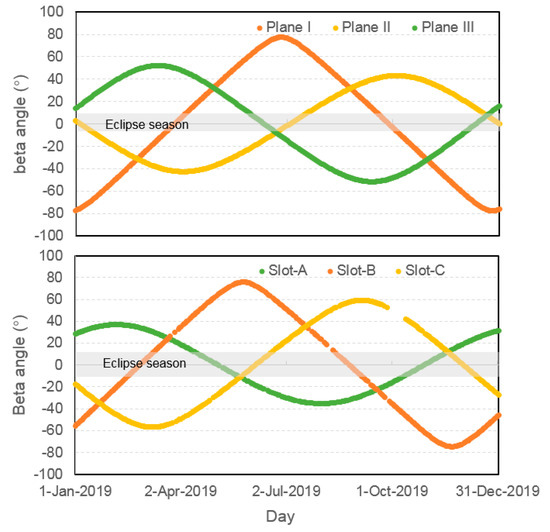
Figure 1.
Elevation of the Sun (β angle) with respect to the BeiDou navigation satellite system (BDS) orbital planes for inclined geostationary orbit (IGSO) (up) and medium earth orbit (MEO) (bottom) satellites from day of year (DOY) 1 to 365, 2019. The shaded area indicates the eclipse seasons.
As all BDS-2 satellites have already been tracked by ground receivers with multi-constellation capacity. Hence, we only focus on the tracking status of BDS-3 satellites here. Currently, the ground L-band tracking data of BDS-3 can be obtained from the IGS and International GNSS Monitoring and Assessment System (iGMAS) network. For the total of the 25 stations of the iGMAS network, the B1I, B3I, B1c, and B2a open-service (OS) signals from all deployed BDS-3 satellites can be tracked. With the release of interface control documents (ICDs) for BDS-3 signals [22], the GNSS receivers of IGS network, mainly from Leica, Trimble, Javad, and Septentrio, are gradually upgraded to track BDS-3 signals. Most of them support tracking the backward-compatible B1I and B3I signals, whereas a few stations can track all BDS-3 OS signals. Figure 2 shows the daily number of IGS and iGMAS stations tracking the representative satellites, i.e., C19, C23, C32, C35, C38, and C59, from DOY 1 to 365, 2019. At the beginning of 2019, there were 93 and 19 stations from IGS and iGMAS network with BDS-3 B1I and B3I signal-tracking capacity, and it increased to 171 and 25 at DOY 365, 2019. However, not all deployed BDS-3 satellites can be tracked by each IGS receiver, possibly due to the limitation of tracking channels. In general, the early-launched satellites can be tracked by more receivers. At the beginning of 2019, except for Javad TRE-3 Delta receiver with ability to track all deployed BDS-3 satellites, Trimble receivers can only track the C16–C30 satellites, and Septentrio receivers with latest firmware can only track C19–C22 and C32–C34 satellites. Hence, the number of stations with C19 tracking capacity is the greatest, followed by C32. With the updates of Trimble NetR9 as well as deployment of Trimble Alloy, the number of stations tracking C23 increased gradually, and even exceeded that of C32 around DOY 180, 2019. Owing to the update of Septentrio firmware, C35 was tracked by more stations, and beyond 100 around DOY 297, 2019. However, for the satellite beyond C37, no more than 30 tracking stations were available, and were mainly from iGMAS. Hence, their PCCs are not estimated in this study.
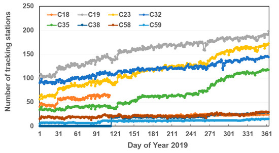
Figure 2.
The number of stations with tracking capacity of the BDS-3 representative satellites, i.e., C19, C23, C32, C35, C38, and C59 satellites from DOY 1 to 365, 2019.
2.2. Satellite and Receiver Antenna Phase Center Corrections
The metadata related to the BDS-2 and BDS-3 spacecrafts was disclosed by CSNO on 9 December 2019 and 25 December 2019 [19], respectively. The published BDS metadata comprises mass, sizes, and optical properties of the main satellite surfaces, eclipse attitude laws, laser retro-reflector array, and PCO for each satellite. Table 1 lists the released PCO information for the B1 and B3 frequency bands and their ionosphere-free (IF) combinations for BDS IGSO and MEO satellites.

Table 1.
Officially released phase center offset (PCO) information of B1 and B3, as well as their ionosphere-free combination for BDS IGSO and MEO satellites (unit: m).
Since April 2019, the IGS ACs have carried out a third reanalysis of the full history of GPS data collected by the IGS global network since 1994 in a fully consistent way using the latest models and methodology. In this reanalysis process, for some types of antenna, the PCCs for BDS OS signals have been calibrated by Geo++ and archived in the ATX file igsR3_2077.atx (available at http://ftp.aiub.unibe.ch/users/villiger/igsR3_2077.atx (accessed on 30 December 2020)). Table 2 lists all antenna/radome with PCC available for BDS B1I and B3I signals in igsR3_2077.atx. The number of stations equipped with these antennas reached more than 160 by the end of 2019.
Table 2.
Antenna/radome combinations with phase center corrections (PCC) available for BDS B1I and B3I signals in igsR3_2077.atx.
3. Data Processing
The Position and Navigation Data Analyst (PANDA) software [23] was modified for estimating raw PCVs and PCOs of BDS satellite antennas. The B1I and B3I signals are selected based on two facts: (1) both BDS-2 and BDS-3 satellites broadcast the two signals, (2) much more receivers can support tracking them. We estimated one-day solutions by using undifferenced IF combinations of dual-frequency code and phase measurements collected by more than 130 ground tracking stations equipped with the antennas in Table 2 and belonging to MGEX and iGMAS from DOY 1 to 365, 2019. The distribution of these stations in Figure 3 shows that they have been able to provide good ground tracking conditions for BDS. Moreover, it also shows the feasibility of PCC estimation based on the receiver antenna PCCs. As PCVs are independent from the reference frame used, hence only one solution was estimated for PCVs. Additionally, two PCO solutions for BDS IGSO and MEO satellites were determined by fixing the scale to that of IGb14 and IGSR3 frame, denoted as the F14 as well as FR3 solution hereafter. As aforementioned, as no more than 30 stations were available with the ability to track satellites with PRN exceeding C38 during the selected period, those satellites were not included for analysis in this study.
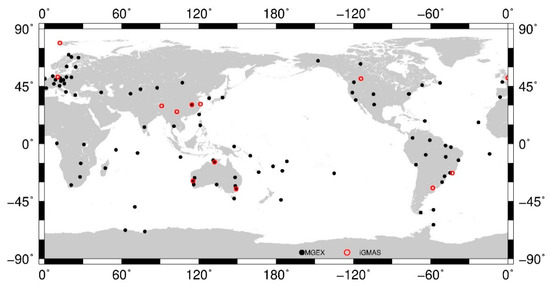
Figure 3.
Distribution of the ground stations used for estimating PCOs and phase center variations (PCVs) of BDS IGSO and MEO satellites. Red circles indicate International GNSS Monitoring and Assessment System (iGMAS) stations, whereas the black ones represent International GNSS Service (IGS) multi-GNSS experiment (MGEX) stations.
The GPS/BDS integrated approach was used to estimate the raw PCVs and PCOs of BDS IGSO and MEO satellites. In this procedure, we used a 24-h arc length, a 5 min sampling rate, a 7° cutoff elevation, and an elevation-dependent weighting. The raw PCV or PCO parameters were estimated with the station coordinates, receiver clocks, inter-system biases, tropospheric zenith total delays, satellite orbits, as well as satellite clocks and earth rotation parameters. To get a reasonable solution for PCOs and PCVs, it is well accepted that these parameters should be estimated by fixing the scale and the receiver antenna PCOs and PCVs. For the PCCs of ground receiver antennas in BDS signal frequencies, the ground calibration models in igsR3_2077.atx were used, and that of GPS L1 and L2 were used in case of no corrections for BDS signals. Although the discrepancy of PCCs for receiver antennas of GPS signals in IGS legacy igs14_2101.atx as well as igsR3_2077.atx is marginal, the GPS PCCs for ground receiver antennas in igs14_2101.atx as well as igsR3_2077.atx were used for the F14 and FR3 solutions to keep the consistency. Correspondingly, the PCC correction models for GPS transmitter antennas were also fixed to the absolute values in igs14_2101.atx as well as igsR3_2077.atx for F14 and FR3 solutions, respectively. It is worth noting that the PCVs as well as horizontal PCOs are the same for GPS transmitter antennas in igsR3_2077.atx. and igs14_2101.atx. However, the discrepancy of Z-PCO reaches +160.0 mm, equivalent to a −1.24 ppb scale shift when IGSR3 was transformed to IGb14.
For BDS IGSO and MEO satellites, the correction models of transmitter antennas were estimated in data processing. The initial values of nadir-dependent PCVs were set as 0, whereas the IGS recommended PCO values in igs14_2101.atx were used as the initial ones. These values were derived based on the CSNO-released BDS PCOs. Considering the correlations between Z-PCO and satellite clock offset as well as the correlations between horizontal PCO and orbital parameters, it was necessary to introduce appropriate constraints to reduce their impact on data processing. It should be mentioned that the signal transmitter located in the Y-axis. Hence, strong constraint was usually used, and it was even fixed to the initial value [11]. Therefore, in this study, the constraints of PCOs with 10.0, 0.1, 10.0 m for X-PCO, Y-PCO and Z-PCO were set to improve the stability of estimates. The PCOs and PCVs for BDS satellites were estimated in two steps. First, with fixing the PCOs to the values in igs14_2101.atx, we calculated the daily raw PCVs for BDS IGSO and MEO satellites. The daily raw PCVs were then converted to daily smooth PCVs. Afterwards, the series of daily PCVs were converted to satellite-specific as well as satellite-block-specific PCVs depending on the satellite manufacturers and types. With the estimated satellite-block-specific PCVs, the daily PCO parameters of each BDS satellite were estimated within IGb14 and IGSR3 frame. The daily PCOs were then converted to satellite-specific PCOs. Table 3 summarizes the strategy used in this study.
Table 3.
Strategy used for PCO and PCV estimation of BDS IGSO and MEO satellites.
It has already been revealed that the scatter of horizontal PCO estimates, particularly for X-PCO, depends on the β-angles [6]. Generally, the larger the β-angles, the greater the scatter. This could be attributed to the correlations between X-PCO and orbital parameters. In previous research performed by Xia et al. [21] and Yan et al. [29], the impacts of the solar radiation pressure (SRP) model on the horizontal PCO estimates have already been investigated and analyzed. They concluded that the 5-parameter CODE Extended Orbit Model (ECOM1) with a prior SRP model was suitable for X-PCO estimation. Hence, in this study, ECOM1 was used with a prior SRP model developed based on a similar approach used for SRP modeling of BDS GEO satellites [28].
4. Results and Validation
4.1. Distribution of Observations
Before analyzing the actual results of the estimation of PCVs and PCOs, it is worth considering the distribution of observations with respect to nadir angle for BDS IGSO and MEO satellites, as shown in Figure 4 for the 1-day solution of DOY 365, 2019 for IGSO C06 and MEO C19 satellites. The reason for selecting these two satellites is that the distribution characteristics of observations from other IGSO or MEO satellites show an obvious consistency with these two satellites. As the IGSO orbital altitude is quite greater than that of MEO satellites, the maximum nadir angle (8.7°) is lower compared to MEO (13.02°). The distribution of observations shows an increasing trend with the increase of the nadir angle, and it drops down dramatically above 8.5° and 13°, as more and more receivers do not track the low elevation data of IGSO and MEO satellites. For estimating raw PCVs, a linear piecewise function model with the maximum nadir angle up to 9° and 13° was built up for IGSO and MEO satellites. As low nadir angles are poorly covered by observations, their estimation of raw PCVs was relatively poorer than others.
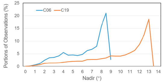
Figure 4.
Distribution of observations with respect to the satellite nadir angle for representative IGSO C06 and MEO C19 satellites.
4.2. Phase Center Variations
As mentioned above, PCVs and PCOs were estimated in two steps. For the estimation of PCV values, we first obtained the daily raw PCVs with the PCOs fixed. Afterwards, the daily raw PCVs were then converted to daily smooth PCVs. With comprehensive quality control as well as an averaging algorithm, the satellite-specific and satellite-block-specific PCV values were obtained and plotted in Figure 5 for BDS-2 IGSO, BDS-2 MEO, and BDS-3 MEO from CAST and SECM, respectively.
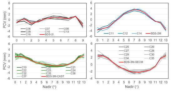
Figure 5.
The satellite-specific and satellite-block-specific PCV values for BDS-2 IGSO, BDS-2 MEO, BDS-3 CAST MEO, and BDS-3 SECM MEO.
For BDS-2 IGSO satellites, the consistency between individual PCV curves were relatively lower than that of MEO satellites, due to higher correlation between PCVs and clock parameters caused by higher orbit height. Disregarding C10, the variations of nadir-dependent phase center were similar with maximum differences up to 1.3 mm between C09 and C16 at a 9° nadir. Hence, the block-specific mean was derived by excluding C10. Moreover, we found that the majority of BDS-2 MEO antennas show a very similar nadir-dependent phase center characteristic with variations from −4.6 to +4.1 mm. The repeatability of the three satellites was within 1.0 mm at a nadir angle above 4°, and below 2.0 mm at a low nadir angle, as less observations were available at a low nadir. Similar performance was observed for BDS-3 MEO from CAST and SECM. However, we found that C35 and C36/C37 show anomalous patterns at a nadir angle of 5° compared to their counterparts from the CAST and SECM group. The reason is not clear, but is possibly due to the number of stations. About 60 stations available could track the three satellites until DOY 200, 2019, and it was about two times less than others. Hence, they have been excluded for deriving the satellite-block-specific PCVs. In general, the differences between the satellite-block-specific mean and the individual PCV curves were below ± 1.0 mm. Using a satellite-block-specific pattern for these antennas instead of satellite-specific ones should therefore be possible without a significant loss of accuracy. The derived satellite-block-specific PCVs are also shown in Figure 5, and their values are listed in Table 4.
Table 4.
Estimated satellite-block-specific PCVs for BDS IGSO and MEO satellites (unit: mm).
4.3. Estimated Phase Center Offsets
For the estimation of the PCOs values of BDS satellites, the above estimated satellite-block-specific PCVs and scale of reference frame were fixed. Additionally, the PCOs corrections with respect to the values in igs14_2101.atx were obtained. To obtain stable results from these daily solutions, we carried out quality control and further analysis of the time series of PCOs estimates.
The satellite-specific PCO estimates including their formal standard deviations, as well as the number of daily solutions, are listed in Table 5. The delta symbol Δ is used to indicate that the parameters are given relative to the CSNO released metadata values for F14 solutions, whereas δ represents the differences of the FR3 solution with respect to F14 estimates. Here, only the offsets of Z-PCO between FR3 and F14 for each satellite are listed, as the discrepancy for the horizontal estimates was within 1.0 mm, due to no impacts of scale on the estimation of horizontal PCOs. The standard deviations illustrate that the precision of the horizontal offset estimates was approximately 10 times better than that of the Z-offsets on average. The standard deviations of IGSO satellites were about two times larger than that of MEO satellites in each component due to relatively poor observation conditions. Moreover, relatively larger standard deviations occurred in the cases of fewer data available, e.g., for C35–C37 satellites. Although more than 300 days of data were processed for them, about one of third were excluded due to poor quality because of fewer stations available before DOY 200, 2019.
Table 5.
Satellite-specific PCOs for F14 and FR3 solutions of BDS IGSO and MEO satellites (unit: cm).
Several meters’ discrepancy was observed between the estimated F14 and the CSNO-released Z-PCO for the BDS-2 IGSO and MEO satellites, and it was already noticed by Dilssner et al. [11] and Guo et al. [12]. However, it is still unclear for the root. On the other hand, the agreement between the estimated F14 and the CSNO released Z-PCO for BDS-3 MEO satellites was good. However, we clearly notice that most of the estimated Z-PCO was larger than the corresponding metadata values. If we compute the average of the Z-PCO estimates of 19 BDS-3 MEO satellites, we obtain a mean value of +98.8 mm. A common bias of this size would impact the station heights and the scale of the terrestrial reference frame. For the FR3 solution, we clearly observed an averaged shift for the Z- PCO up to about −414.9 mm, and −174.1 cm for the IGSO and MEO satellites, respectively, which is equivalent to a scale increase of +1.27 ppb, quite closed to the scale differences (+1.24 ppb) when IGb14 was transformed to IGSR3. Besides the Z-PCO, the horizontal PCO estimates partly show significant deviations from their metadata values. For the X- PCO of C06, C07, and C08, we found biases of −16.65, −12.02 and −16.40 cm, respectively. Similar results have been obtained by Xia et al. [21] and Yan et al. [29]; the reasons for the discrepancy need further investigation.
4.4. Validation
Subsequently, we investigated the effect of the new PCOs and PCVs of BDS satellites on the orbit consistency and the station coordinates with the data from DOY 335 to 362, 2019. For this purpose, three solutions were obtained taking account of the PCC estimates as well as the ground antenna calibrations for BDS signals. Specifically, the solution labeled as IGS was determined based on the igs14_2101.atx, taking into account the ground antenna calibrations for BDS signals taken from igsR3_2077.atx. For the solutions labeled F14 and FR3, the updated igsR3_2077.atx was compiled to include the BDS PCC estimates in IGb14 and IGSR3 frame.
4.4.1. Orbit Consistency
Orbit boundary disclosure (OBD) is used for the evaluation of the orbit consistency. The average 3D RMS of the BDS-3 OBD for each satellite with different antenna models are shown in Figure 6. It is clear to see that the OBDs of BDS satellites have been reduced by using the two kinds of calibrated PCO and PCV estimates, i.e., F14 and FR3, compared to that of using CSNO released values. Moreover, the discrepancy of OBDs between F14 and FR3 is marginal (only 4 mm on average), as expected, as the PCO shifts along radial direction have been assimilated by the clock parameters.
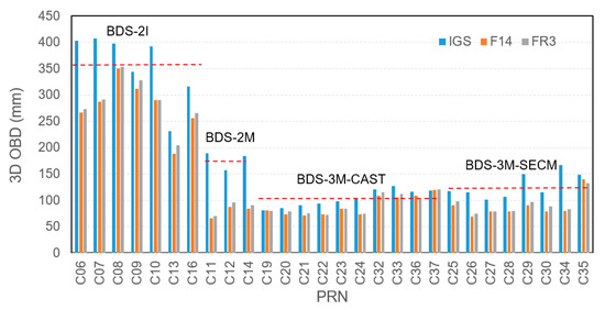
Figure 6.
Influences of the three kinds of antenna models on orbit boundary disclosure for BDS satellites. The solution based on the igs14_2102.atx antenna model is represented as IGS. The BDS orbit solutions using new satellite antenna PCCs are represented as F14 as well as FR3.
We also observed that the OBDs were reduced by about 55.0% from 176.6 mm to 79.5 mm for BDS-2 MEO, whereas the reduction for BDS-2 IGSO was about 21.7% from 356.0 to 278.9 mm. With respect to the approximate 13.2% reduction for BDS-3 CAST MEO satellites, the OBDs were reduced by 30.9% for BDS-3 SECM satellites, making 3D OBD achieve around 90.0 mm for both kinds of MEO satellites. In addition, we also observed that the OBD reduction was smaller for C35-C37 than that of others, possibly due to fewer ground stations available in the process of estimating PCC and precise orbit determination.
4.4.2. Coordinates
A BDS-only precise point positioning (PPP) was performed using the three sets of daily orbit and clock parameters from the global network solutions determined in the last subsection. Furthermore, two sets of GPS-only PPP were also performed with the orbits and clocks determined within IGb14 and IGSR3 frame, respectively. The daily station coordinates, hourly constant tropospheric zenith pass delay, carrier phase ambiguities and epoch-wise receiver clocks were solved. Coordinatingly, three BDS-only (BDS-IGS, BDS-F14, and BDS-FR3), as well as two GPS-only solutions (GPS-F14 and GPS-FR3), were obtained. The seven-parameter Helmert transformations were carried out to compare the BDS-IGS, BDS-F14, and GPS-F14 PPP-derived coordinates with the IGS legacy daily final estimates in IGb14 frame, whereas the GPS-FR3 and BDS-FR3 solutions were compared to the initial combined coordinates of the third IGS reprocess, available at ftp://igs-rf.ign.fr/pub/repro3_tests/2008-2019/IGS1R03TST/ (accessed on 30 December 2020), with Helmert transformations. The scale parameters obtained from the Helmert transformations gave the assessment of consistency of the GPS- and BDS-derived station heights with respect to IGb14 as well as IGSR3 frame. The scale bias between the GPS- and BDS-only PPP coordinates and the IGb14 and IGSR3 reference frame are shown in Figure 7.
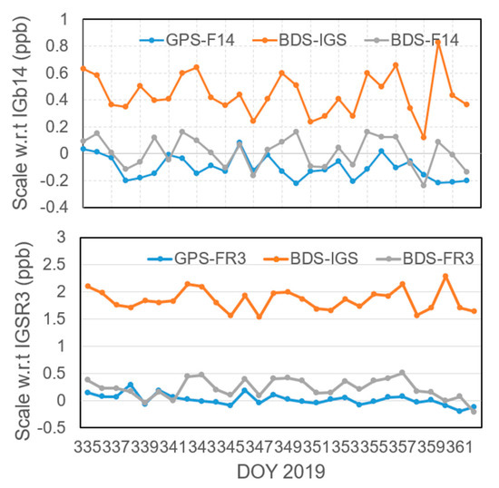
Figure 7.
Scale bias between the GPS- and BDS-only precise point positioning (PPP) coordinates and the IGb14 (up) and IGSR3 (bottom) reference frame. The GPS- and BDS-only solutions based on the igs14_2102.atx antenna model and GPS-only with igsR3_2077.atx are represented as GPS-F14 as well as BDS-IGS, and GPS-FR3 respectively. The BDS-only solutions using new satellite antenna PCCs are represented as BDS-F14 as well as BDS-FR3.
We clearly noticed a significant bias for BDS-IGS PPP solutions, whereas it was significantly reduced when applying BDS F14 PCC estimates. The mean scale parameter of the BDS-IGS and BDS-F14 solutions was +0.446 ± 0.153 ppb and +0.012 ± 0.111 ppb, respectively. It clearly demonstrated that the discrepancy between BDS-derived station heights with IGS recommended PCOs and IGS legacy solutions decreased when the new BDS satellite antenna corrections were introduced. For the GPS-F14 PPP solution, there was a bias up to −0.102 ± 0.084 ppb, close to the scale inconsistency between our software and the IGS antenna model. Previously, Guo [14] estimated the PCOs for GPS with 31 days data from 145 ground stations and demonstrated that the averaging Z-PCO difference between the estimated and IGS recommended one was 14.5 mm, equivalent to −0.095 ppb. Hence, we believe the scale inconsistency between PANDA and IGS antenna model is within a level of −0.1 ppb, and is possibly caused by the data processing strategy used, as well as the minor inconsistency of error models in the software. Without a doubt, this inconsistency will be assimilated into the BDS PCO estimation. However, its impact is minor, compared to the agreement (about 4 cm) between the two GPS PCO solutions estimated by GFZ and Technische Universität München (TUM) [4], as well as the accuracy (a few cm) of the IGS antenna model [30]. Furthermore, the residuals of the BDS-derived station heights (after the Helmert transformation) were slightly reduced from 9.65 to 8.62 mm for the BDS-IGS and BDS-F14 solutions. This demonstrates that great accuracy was achieved for the BDS-only solution, and it will be improved with more BDS satellites used for positioning.
For the GPS-R3 solution, the mean scale parameter was about +0.021 ± 0.101 ppb with respect to the IGSR3 solutions, whereas the scale bias was about +0.226 ± 0.175 ppb between the BDS-FR3 solutions and IGSR3 frame. The bias up to +0.226 ppb clearly demonstrates that this inconsistency between PANDA and IGS antenna model was assimilated into the BDS PCO estimation. However, it was still within the confident level, as the standard derivation was about 0.175 ppb. In the bottom subplot of Figure 7, the scale bias of BDS-IGS with respect to IGSR3 frame is also plotted to demonstrate the scale inconsistency between BDS-released and Galileo-released PCO values. It is clear to show that the scale derived from BDS and Galileo-released PCOs is not consistent, and the bias reach +1.854 ± 0.191 ppb. Moreover, the reduction of scale bias for BDS solutions in IGb14 as well as IGSR3 shows the good consistency of PCO/PCC estimates for BDS with other systems of GPS/GLONASS antenna offsets is achieved.
5. Conclusions
In this contribution, one year of undifferenced dual-frequency (B1I and B3I) measurement data from global tracking networks of MGEX and iGMAS were analyzed to evaluate whether the terrestrial scale derived from released BDS PCOs is consistent with that obtained with released Galileo PCOs, and to obtain the PCO estimates for BDS in IGb14 and IGSR3 frame for preparing BDS for IGS repro3 and legacy analysis.
From the analysis of the PCV estimates, it was found that the C10 satellite shows a different PCV pattern with respect to its counterparts. Moreover, there was a lower repeatability for C35–C37 satellites, and the main reason was the small number of stations which can track these satellites. However, for other satellites, their PCV shows quite good consistency (bellow 2.0 mm). Hence, the satellite-block-specific PCV estimates were derived. From the analysis of the PCOs estimates, we focus on the impacts of scale on the PCO estimates. The Z-PCO shifts about −414.9 mm, and −174.0 mm for BDS IGSO and MEO satellites, when the IGSR3 frame was used instead of IGb14. The −174.0 mm Z-PCO shifts equals about +1.27 ppb at the height (about 21200 km) of BDS MEO satellites, which is quite consistent with the scale bias +1.24 ppb when IGb14 was transformed to IGSR3.
To verify the influences and reliability of the PCOs and PCVs estimates, we reprocessed the data with three different schemes of satellites’ and receivers’ antenna model combinations and analyzed the results from orbit consistency and coordinates. From the result of validation, we found that compared with the use of only the CSNO-released PCOs, the orbit consistency could benefit from the estimated model of the satellite antenna phase center, particularly for BDS-2 MEO and BDS-3 SECM MEO satellites. With modeling PCCs, the 3D OBD achieves about 90.0 mm for BDS-3 MEO satellites. We also notice that the scale bias by using IGS recommended PCOs was significantly reduced when applying BDS PCC estimates. The residuals of the BDS-derived station heights are slightly reduced from 9.65 to 8.62 mm after the Helmert transformation. This demonstrates good consistency of PCO/PCC estimates in IGb14 and IGSR3 frame for BDS with other systems of GPS/GLONASS antenna offsets is achieved. Most importantly, the results demonstrate that the scale derived with BDS-released and Galileo-released PCOs is not consistent, and the bias is about +1.854 ± 0.191 ppb.
However, it must be mentioned that the estimated results of PCOs and PCVs depend on a year’s data. A longer data set should be used to reduce the seasonal effects for obtaining more reliable satellite antenna models. In addition, the satellites beyond C37 should be included for further analysis.
Author Contributions
Conceptualization, J.G. and Z.Q.; data process and analysis, Z.Q.; writing—original draft preparation, Z.Q.; writing—review and editing, J.G. and Z.Q.; supervision, Q.Z.; funding acquisition, J.G. and Q.Z. All authors have read and agreed to the published version of the manuscript.
Funding
This research was funded by the National Natural Science Foundation of China (grant number 41974035, 41674004), Young Elite Scientists Sponsorship Program by CAST (grant number 2018QNRC001).
Data Availability Statement
Publicly available datasets were analyzed in this study. The high quality GNSS data provided by IGS and iGMAS can be found at the IGS website (ftps://gdc.cddis.eosdis.nasa.gov (accessed on 30 December 2020)) and iGMAS website, respectively. The initial combined coordinates of the third IGS reprocess available at ftp://igs-rf.ign.fr/pub/repro3_tests/2008-2019/IGS1R03TST (accessed on 30 December 2020). The ATX file igsR3_2077.atx can be found at http://ftp.aiub.unibe.ch/users/villiger/igsR3_2077.atx (accessed on 30 December 2020).
Acknowledgments
The authors would like to thank IGS and iGMAS for providing available high quality GNSS data, and Paul Rebischung for IGN to provide the initial combination results of the third IGS reprocess.
Conflicts of Interest
The authors declare no conflict of interest.
References
- CSNO. Development of the BeiDou Navigation Satellite System. China Satellite Navigation Office. Available online: http://www.beidou.gov.cn/xt/gfxz/201912/P020191227430565455478.pdf (accessed on 30 December 2020).
- Montenbruck, O.; Steigenberger, P.; Prange, L.; Deng, Z.; Zhao, Q.; Perosanz, F.; Romero, I.; Noll, C.; Stürze, A.; Weber, G.; et al. The Multi-GNSS Experiment (MGEX) of the International GNSS Service (IGS)—Achievements, prospects and challenges. Adv. Space Res. 2017, 59, 1671–1697. [Google Scholar] [CrossRef]
- Sakic, P.; Mansur, G.; Männel, B. A Prototype for a Multi-GNSS Orbit Combination. In Proceedings of the European Navigation Conference, Bonn, Germany, 23–24 November 2020; pp. 1–11. [Google Scholar] [CrossRef]
- Schmid, R.; Steigenberger, P.; Gendt, G.; Ge, M.; Rothacher, M. Generation of a consistent absolute phase-center correction model for GPS receiver and satellite antennas. J. Geod. 2007, 81, 781–798. [Google Scholar] [CrossRef]
- Dilssner, F.; Springer, T.; Flohrer, C.; Dow, J. Estimation of phase center corrections for GLONASS-M satellite antennas. J. Geod. 2010, 84, 467–480. [Google Scholar] [CrossRef]
- Montenbruck, O.; Schmid, R.; Mercier, F.; Steigenberger, P.; Noll, C.; Fatkulin, R.; Kogure, S.; Ganeshan, A. GNSS satellite geometry and attitude models. Adv. Space Res. 2015, 56, 1015–1029. [Google Scholar] [CrossRef]
- Steigenberger, P.; Fritsche, M.; Dach, R.; Schmid, R.; Montenbruck, O.; Uhlemann, M.; Prange, L. Estimation of satellite antenna phase center offsets for Galileo. J. Geod. 2016, 90, 773–785. [Google Scholar] [CrossRef]
- Ge, M.; Gendt, G.; Dick, G.; Zhang, F.; Reigber, C. Impact of GPS satellite antenna offsets on scale changes in global network solutions. Geophys. Res. Lett. 2005, 32, L06310. [Google Scholar] [CrossRef]
- Zhu, S.Y.; Massmann, F.-H.; Yu, Y.; Reigber, C. Satellite antenna phase center offsets and scale errors in GPS solutions. J. Geod. 2003, 76, 668–672. [Google Scholar] [CrossRef]
- Schmid, R.; Rothacher, M.; Thaller, D.; Steigenberger, P. Absolute phase center corrections of satellite and receiver antennas. GPS Solut. 2005, 9, 283–293. [Google Scholar] [CrossRef]
- Dilssner, F.; Springer, T.; Schönemann, E. Estimation of Satellite Antenna Phase Center Corrections for BeiDou. In Proceedings of the IGS Network, Data and Analysis Center Workshop, Pasadena, CA, USA, 23–27 June 2014. [Google Scholar]
- Guo, J.; Xu, X.; Zhao, Q.; Liu, J. Precise orbit determination for quad-constellation satellites at Wuhan University: Strategy, result validation, and comparison. J. Geod. 2016, 90, 143–159. [Google Scholar] [CrossRef]
- Huang, G.; Yan, X.; Zhang, Q.; Liu, C.; Wang, L.; Qin, Z. Estimation of antenna phase center offset for BDS IGSO and MEO satellites. GPS Solut. 2018, 22, 49. [Google Scholar] [CrossRef]
- Guo, J. The Impacts of Attitude, Solar Radiation and Function Model on Precise Orbit Determination for GNSS Satellites. Ph.D. Thesis, Wuhan University, Wuhan, China, 2014. [Google Scholar]
- GSC. Galileo Satellite Metadata, European GNSS Service Centre. Available online: https://www.gsc-europa.eu/support-to-developers/galileo-satellite-metadata (accessed on 1 January 2021).
- Villiger, A.; Dach, R.; Schaer, S.; Prange, L.; Zimmermann, F.; Kuhlmann, H.; Wübbena, G.; Schmitz, M.; Beutler, G.; Jäggi, A. GNSS scale determination using calibrated receiver and Galileo satellite antenna patterns. J. Geod. 2020, 94, 93. [Google Scholar] [CrossRef]
- Männel, B.; Brandt, A.; Bradke, M.; Sakic, P.; Brack, A.; Nischan, T. Status of IGS Reprocessing Activities at GFZ. In International Association of Geodesy Symposia; Springer: Berlin, Germany, 2020. [Google Scholar] [CrossRef]
- Huang, W.; Männel, B.; Brack, A.; Schuh, H. Two methods to determine scale-independent GPS PCOs and GNSS-based terrestrial scale: Comparison and cross-check. GPS Solut. 2020, 25, 4. [Google Scholar] [CrossRef]
- CSNO. Satellite Information of BDS. China Satellite Navigation Office. Available online: http://en.beidou.gov.cn/SYSTEMS/Officialdocument/201912/P020200103556125703019.rar (accessed on 30 December 2020).
- Springer, T.; Agrotis, L.; Dilssner, F.; Feltens, J.; Van Kints, M.; Mayer, V.; Romero, I.; Enderle, W.; Schoenemann, E.; Zandbergen, R. The ESA/ESOC IGS Analysis Centre Technical Report. 2019. Available online: ftp://ftp.aiub.unibe.ch/users/villiger/2019_techreport.pdf (accessed on 30 December 2020).
- Xia, F.; Ye, S.; Chen, D.; Wu, J.; Wang, C.; Sun, W. Estimation of antenna phase center offsets for BeiDou IGSO and MEO satellites. GPS Solut. 2020, 24, 90. [Google Scholar] [CrossRef]
- CSNO. BeiDou Navigation Satellite System Signal in Space Interface Control Document. China Satellite Navigation Office. Available online: http://www.beidou.gov.cn/xt/gfxz/201902/P020190227593621142475.pdf (accessed on 30 December 2020).
- Liu, J.; Ge, M. PANDA software and its preliminary result of positioning and orbit determination. Wuhan Univ. J. Nat. Sci. 2003, 8, 603. [Google Scholar] [CrossRef]
- Saastamoinen, J. Contributions to the theory of atmospheric refraction. Bull. Géodésique 1972, 105, 279–298. [Google Scholar] [CrossRef]
- Boehm, J.; Niell, A.E.; Tregoning, P.; Schuh, H. Global Mapping Function (GMF): A new empirical mapping function based on numerical weather model data. Geophys. Res. Lett. 2006, 25. [Google Scholar] [CrossRef]
- Boehm, J.; Heinkelmann, R.; Schuh, H. Short Note: A global model of pressure and temperature for geodetic applications. J. Geod. 2007, 81, 679–683. [Google Scholar] [CrossRef]
- Beutler, G.; Brockmann, E.; Gurtner, W.; Hugentobler, U.; Mervart, L.; Rothacher, M.; Verdun, A. Extended Orbit Modeling Techniques at the CODE Processing Center of the International GPS Service for Geodynamics (IGS): Theory and Initial Results. Manuscr. Geod. 1994, 19, 367–386. [Google Scholar]
- Wang, C. Solar Radiation Pressure Modeling for BeiDou Navigation Satellites. Ph.D. Thesis, Wuhan University, Wuhan, China, 2019. [Google Scholar]
- Yan, X.; Huang, G.; Zhang, Q.; Wang, L.; Qin, Z.; Xie, S. Estimation of the Antenna Phase Center Correction Model for the BeiDou-3 MEO Satellites. Remote Sens. 2019, 11, 2850. [Google Scholar] [CrossRef]
- Schmid, R.; Dach, R.; Collilieux, X.; Jäggi, A.; Schmitz, M.; Dilssner, F. Absolute IGS antenna phase center model igs08.atx: Status and potential improvements. J. Geod. 2016, 90, 343–364. [Google Scholar] [CrossRef]


Publisher’s Note: MDPI stays neutral with regard to jurisdictional claims in published maps and institutional affiliations. |
© 2021 by the authors. Licensee MDPI, Basel, Switzerland. This article is an open access article distributed under the terms and conditions of the Creative Commons Attribution (CC BY) license (http://creativecommons.org/licenses/by/4.0/).