Article

Mapping Drainage Structures Using Airborne Laser Scanning by Incorporating Road Centerline Information

Department of Geomatics, National Cheng Kung University, No.1, University Road, Tainan 701, Taiwan
*
Author to whom correspondence should be addressed.
Remote Sens. 2021, 13(3), 463; https://doi.org/10.3390/rs13030463
Submission received: 9 December 2020 / Revised: 15 January 2021 / Accepted: 22 January 2021 / Published: 28 January 2021
(This article belongs to the Special Issue Laser Scanning and Point Cloud Processing)

Abstract

:
Wide-area drainage structure (DS) mapping is of great concern, as many DSs are reaching the end of their design life and information on their location is usually absent. Recently, airborne laser scanning (ALS) has been proven useful for DS mapping through manual methods using ALS-derived digital elevation models (DEMs) and hillshade images. However, manual methods are slow and labor-intensive. To overcome these limitations, this paper proposes an automated DS mapping algorithm (DSMA) using classified ALS point clouds and road centerline information. The DSMA begins with removing ALS ground points within the buffer of the road centerlines; the size of the buffer varies according to different road classes. An ALS-modified DEM (ALS-mDEM) is then generated from the remaining ground points. A drainage network (DN) is derived from the ALS-mDEM. Candidate DSs are then obtained by intersecting the DN with the road centerlines. Finally, a refinement buffer of 15 m is placed around each candidate DS to prevent duplicate DS from being generated in close proximity. A total area of 50 km2, including an urban site and a rural site, in Vermont, USA, was used to assess the DSMA. Based on the road functional classification scheme of the Federal Highway Administration (FHWA), the centerline information regarding FHWA roads was obtained from a public data portal. The centerline information on non-FHWA roads, i.e., private roads and streets, was derived from the impervious surface data of a land cover dataset. A benchmark DS dataset was gathered from the transport agency of Vermont and was further augmented using Google Earth Street View images by the authors. The one-to-one correspondence between the benchmark DS and mapped DS for these two sites was then established. The positional accuracy was assessed by computing the Euclidian distance between the benchmark DS and mapped DS. The mean positional accuracy for the urban site and rural site were 13.5 m and 15.8 m, respectively. F1-scores were calculated to assess the prediction accuracy. For FHWA roads, the F1-scores were 0.87 and 0.94 for the urban site and rural site, respectively. For non-FHWA roads, the F1-scores were 0.72 and 0.74 for the urban site and rural site, respectively.

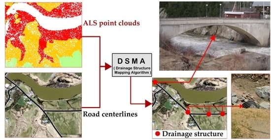
Graphical Abstract

1. Introduction

A bridge is a structure constructed to carry a road or a pathway over a watercourse (i.e., a river or a stream). A culvert is a tunnel structure that carries a watercourse underneath a road, or through another type of obstruction, to a natural drainage point [1]. To clarify the terminology used in this paper, the term “drainage structures” (DS) is used when referring to both a bridge and a culvert collectively. The Global Roads Inventory Project (GRIP) has estimated over 21 million kilometers of global road infrastructure comprised of billions of DS [2,3]. In the United States, the state Department of Transportation (DOT) is responsible for the mapping and maintenance of DS in a state-wide capacity [4]. DS that are not properly maintained can cause disaster and serious economic loss following extreme weather conditions [5,6]. The American Society of Civil Engineers (ASCE) has reported that almost 1.6 trillion dollars are required through various bonds and public funds to update the oldest DS infrastructures nationwide [2,7]. Nevertheless, DS locations are not always mapped or even known by DOTs [8,9]. Consequently, most state DOTs are facing the challenge of extensively mapping their locations [7,10].
In the broadest context, the DS dataset plays a vital role among several Earth Science disciplines [11]. The DS dataset is used in hydrologic modeling, hydraulic modeling, geomorphology, flood inundation modeling, and river system hydrology [12,13,14]. Liu and Merwade (2018) reported uncertainty in flood inundation modeling arising from the lack of detailed DS locations at the stream network scale [15]. Webster et al. (2006) manually mapped and incorporated the DS locations in flood risk modeling to avoid such uncertainties using high-resolution airborne laser scanning (ALS) topographic data [16]. Pinos et al. (2019) found that the hydrologic engineering river analysis system (HEC-RAS) 2D is highly sensitive to the inclusion of the DS dataset, which was manually incorporated in the HEC-RAS 2D model in their research [17]. In the Remote Sensing (RS) context, many researchers reported on the lack of wide-area DS maps to correct the watercourse pathways in digital elevation models (DEMs) by removing man-made obstructions, e.g., bridges, culverts [18]. Arendt et al. (2020) used a combination of remote sensing techniques, e.g., Google Earth (GE) high-resolution satellite images and Global Positioning System (GPS), to collect DS datasets in order to improve TanDEM-X (TerraSAR-X add-on for Digital Elevation Model) [19], therefore making the DS locations the most valued form of data.
The DS locations are mapped by GPS field surveys or by using remotely sensed data, GIS-based methods or a combination of these techniques [19,20]. The field surveys are based on GPS [18,20,21,22]. However, field surveys are slow and encumbered by weather conditions [23]. Image interpretation from satellites or orthophotos for mapping DS using on-screen digitizing has been reported. Image interpretation is labor-intensive and only DS over watercourses of substantial sizes can be mapped. DS mapping was therefore reported to be limited due to image resolution, canopy cover, and the influence of dry and wet seasons, leading to difficulties in effectively mapping DS found underneath such thick canopies [21]. Geographical information system (GIS)-based mapping [24] finds DS locations by intersecting road centerlines with manually delineated watercourses (e.g., the United States Geological Survey (USGS) hydrographic dataset) [25,26]. The manual delineation of the watercourses is subject to some inherent errors associated with image scanning quality (i.e., the dpi at which maps were scanned), vectorization (i.e., the quality of tracing data from raster maps), cartographer image interpretation (i.e., how well the watercourses were interpreted by the cartographer on screen), and the map scale at which data were collected. The aforementioned inherent errors could result in the mapping of watercourses with various degrees of accuracy and completeness [25]. Therefore, mapping DS by intersecting a manually mapped drainage network (DN) with road centerlines is frequently biased toward DS mounted over large rivers and streams [27].
Airborne laser scanning has facilitated the high resolution and precise portrayal of terrain heights over large expanses [28]. A typical airborne laser scanning system entails a laser scanner, an inertial navigation system (IMU), and differential GPS-gathering terrain heights with height accuracies in the range of 10–15 cm. The onboard laser scanner is capable of collecting discrete measurements of terrain heights in the range of 1–200 pts/m2 [29]. ALS ground points have been frequently utilized to acquire digital elevation models (DEMs) and, later, to extract DN over vast expanses [30].
To date, there have been few efforts leveraging the use of ALS-derived DEMs and hillshade to manually map DS [31,32]. However, automated methods to map DS from ALS point clouds have not yet been fully developed. This paper aims to propose an automated DSMA using classified ALS point clouds by incorporating road centerline information.
The rest of the article is organized into six sections. Following the introduction in Section 1, Section 2 describes the two selected sites, along with the acquired datasets used in this paper. Section 3 illuminates the proposed DSMA, where an in-depth algorithm workflow is explained. Well-established research methods were also utilized to quantify the algorithm performance in terms of the positional and prediction accuracies of the mapped DS. In Section 4, the results are presented and explained. In Section 5, the proposed DSMA pros and cons are discussed briefly. Section 6 concludes the paper by highlighting the significant findings of the proposed algorithm.

2. Study Sites and Available Datasets

2.1. Study Sites

The proposed DSMA was tested in Northern Vermont, USA (Figure 1). Land-use land-cover (LULC) data obtained from Vermont Center for Geographic Information (VCGI) [33] shows that Site A (Figure 1a) has a more impervious surface area (ISA), e.g., residential and commercial, compared to Site B (Figure 1b), which predominantly contains agricultural areas. The two sites cover an accumulated area of 50 km2 (Figure 1), as we intended to show the ability of the DSMA to process data over large areas.
Site A is comprised of St. Alban city and some adjoining areas, with a latitude and longitude of 73°1′17.94″ W, and 44°58′5.41″ N, respectively. Site A spans an area of 14 km2 with an elevation range from 85 m to 258 m. The St. Alban city urban area is largely comprised of flat terrain (Figure 1c). Site B is located in a rural part of northern Vermont at a latitude and longitude of 72°48′7.84″ W and 44°54′41.76″ N, respectively, and covers an area of 36 km2. The topography is hilly with an elevation range from 107 m to 273 m, as shown in Figure 1d. The terrain has slope variations in the range of 0°–20°. The site slope values were obtained from ALS-DEM created at a ground sampling distance (GSD) of 0.5 m from the acquired ALS point clouds (see Section 2.2.1). The lower slope values (i.e., 0°) are frequently found along the Missisquoi River flood plains (see elevation map in Figure 1d).
According to their geographical characteristics, Sites A and B are referred to as “urban” and “rural” sites in this article.

2.2. Datasets

2.2.1. ALS Point Clouds

The DSMA study sites (Figure 1) were surveyed using the Leica ALS50II laser scanner during leaf-off conditions in November 2008 for Site A (Figure 1c) and April 2009 for Site B (Figure 1d), with no snow cover on the ground [34]. The ALS scanners were flown at an altitude of 1350 m in 2008 for Site A and at 1371 m altitude in 2009 for Site B, with four returns of each outgoing laser pulse at 150 kHz with a beam divergence of 0.22 mrad, and a nominal side overlap of 36%. This resulted in an average point density of 2 pts/m2. The field validation over different land cover types, e.g., bare earth, buildings, and grass showed vertical accuracy with a root mean square error of 0.08 m [34]. The laser point clouds were classified into ALS ground and non-ground points. We obtained classified ALS point clouds that were made freely available on OpenTopography by the USGS [34]. The acquired ALS point clouds were available in the Vermont State Plane NAD83 (2007) coordinate system.

2.2.2. Centerlines of FHWA Roads

The Vermont Transportation(VT) road centerlines were acquired from the Vermont Open Geodata portal [35]. The VT road centerlines follow the road functional classification scheme developed by the Federal Highway Administration (FHWA) [35] and are comprised of four major road classes of interstate highways, arterials, collectors, and locals. The interstate highways spread nationwide by providing the highest speed and uninterrupted mobility. Arterials are highways and freeways within a state and are directly connected with the interstate highways. Collectors link state arterials and state local roads. Locals are the road networks in residential and industrial areas [36]. It is noted that the VT road centerline does not account for residential streets and private roads because they do not fall under the jurisdiction of the FHWA. For the rest of the paper, the VT road centerlines are referred to as “FHWA roads” (denoted by the black lines in Figure 2).

2.2.3. Centerlines of Non-FHWA Roads

To account for the road centerlines of residential streets and private roads that were not available using the VT road centerlines, an impervious surface area (ISA) map was acquired from the Vermont Center for Geographic Information (VCGI) [37]. Impervious surfaces are anthropogenic surfaces through which water cannot infiltrate into the soil [38]. The ISA was mapped as a vector polygon for 2011 using object-based image analysis (OBIA). The ISAs of residential streets and private roads were mapped with an overall accuracy of 99% [33]. To clarify the terminology used in this paper, the centerlines of residential streets and private roads are referred to as “non-FHWA roads”. The ISAs were comprised of polygon features, which were then processed to obtain the centerlines of non-FHWA roads using the skeleton method [39] (denoted by the yellow lines in Figure 2).

2.2.4. Benchmark DS Dataset

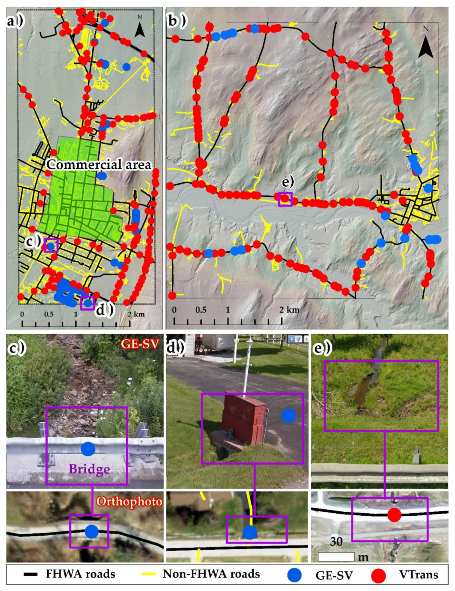
A benchmark DS dataset was acquired from the Vermont agency of transportation (VTrans), covering the interstates and state highways, arterials, and collector roads (see Section 2.2.2) [40]. The VTrans benchmark DS dataset was selected due to its high reliability because VTrans conducted GPS field surveys to map bridges and culverts in a state-wide capacity (see red dots in Figure 2a,b). The DS locations were marked at the center of the road (denoted by the red dots in Figure 2e). The VTrans DS dataset was unavailable for FHWA locals, non-FHWA residential streets and private roads (Section 2.2.3).
In order to acquire the DS dataset for FHWA local and non-FHWA roads, we augmented the DS along with residential streets, locals, and private roads using GE Street View (GE-SV) images (blue dots in Figure 2a,b). GE-SV images are very high-resolution panoramic images contributed by Google (Google LLC., Mountain View, CA, USA) [19,41]. To have consistent positional accuracy compared to the VTrans DS dataset, the locations of augmented DS were marked at the center of the road (blue dots in Figure 2c). Because the commercial area of St. Alban City (shown as a green region in Figure 2a) carries the watercourses underground, the DS dataset for this area is not available. The DS datasets collected from VTrans and augmented from GE-SV were combined, ensuring that both datasets did not overlap, and the result is herein referred to as the “benchmark DS dataset” (Table 1).

2.2.5. Orthophotos

Orthophotos of the leaf-off seasons at a GSD of 0.5 m for 2009 were acquired from the Vermont imagery program [42] for two sites. The orthophotos were used for displaying data and results (Figure 2c–e). All datasets, e.g., FHWA, non-FHWA roads, the benchmark DS dataset, and orthophotos were projected onto the Vermont State Plane NAD83 (2007) coordinate system to match with the coordinate system of the ALS point clouds (Section 2.2.1).

3. Methods

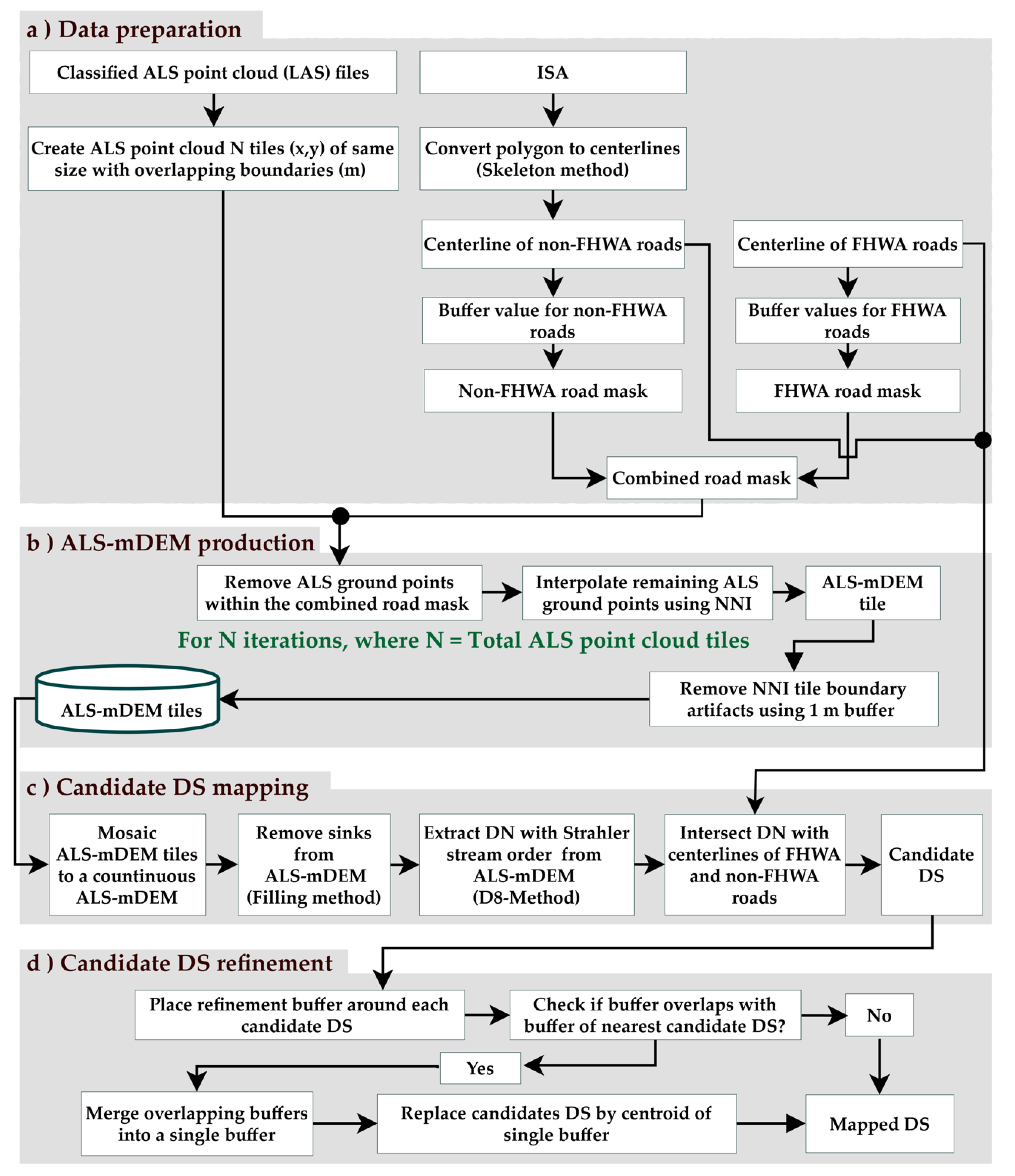
The algorithm proceeds through four stages, as shown in Figure 3. Each stage is briefly explained in the following sub-sections.

3.1. Data Preparation

3.1.1. ALS Data Tiling

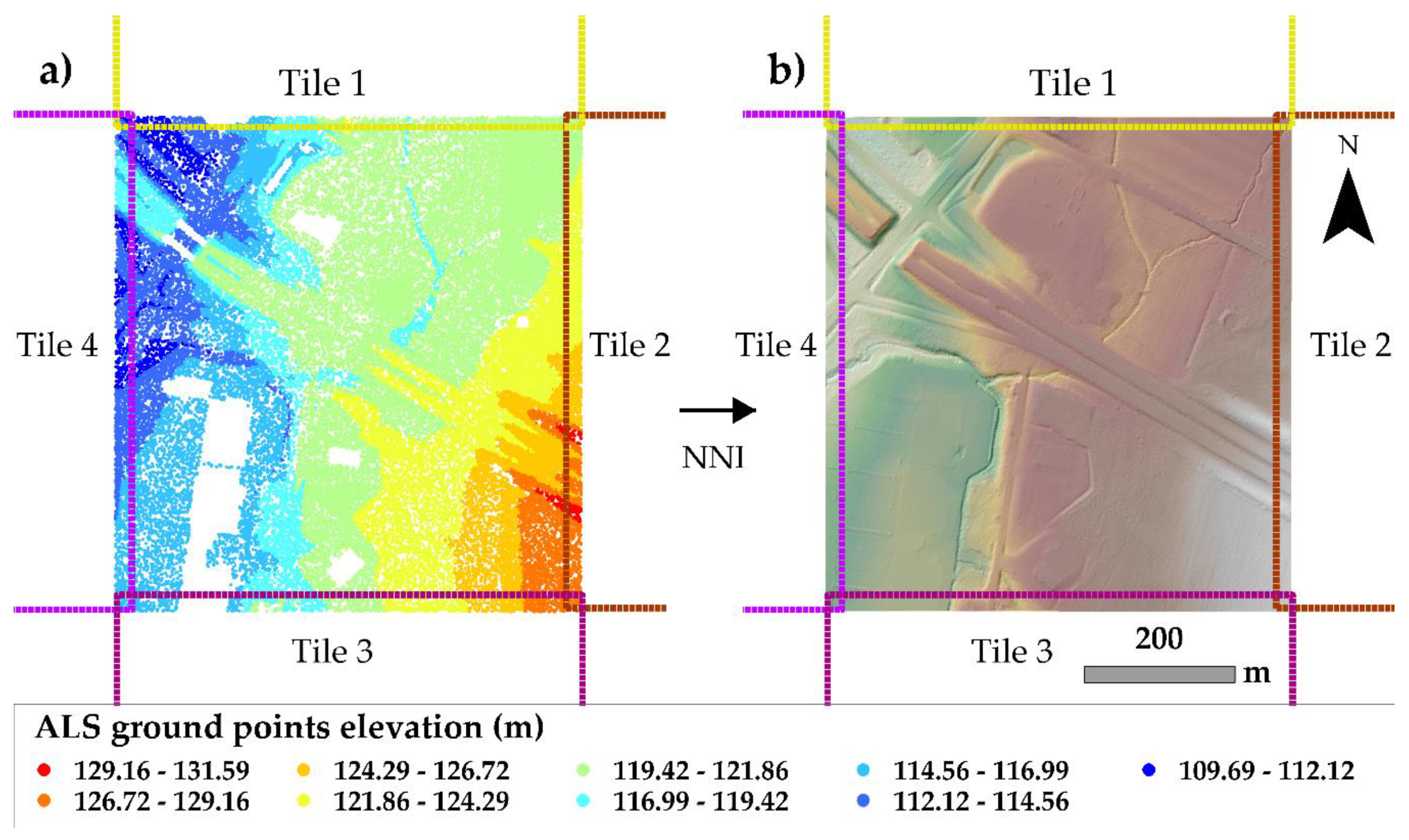
The ALS point clouds were obtained from OpenTopography (see Section 2.2.1) for two sites (Figure 1). In practice, ALS acquisitions are provided as hundreds or even thousands of files, causing memory allocation errors due to their large size and massive data volume. Moreover, we adopted the natural neighbor interpolation (NNI) [43], which is implemented in ArcGIS desktop version 10.8.1 and has a maximum limit of 15 million input points. The ALS point clouds were therefore processed into tiles (Figure 3a) of the same size using the lidR package [44], where tiles overlap their boundaries with the four immediately neighboring tiles (Figure 4a). The tile boundary overlap is used to eliminate tile boundary artifacts caused by NNI (see Section 3.2). The maximum tile size (x, y) of 4 × 4 km with a 1 m boundary overlap is used in this paper.

3.1.2. Creating a Combined Mask of FHWA and Non-FHWA Roads

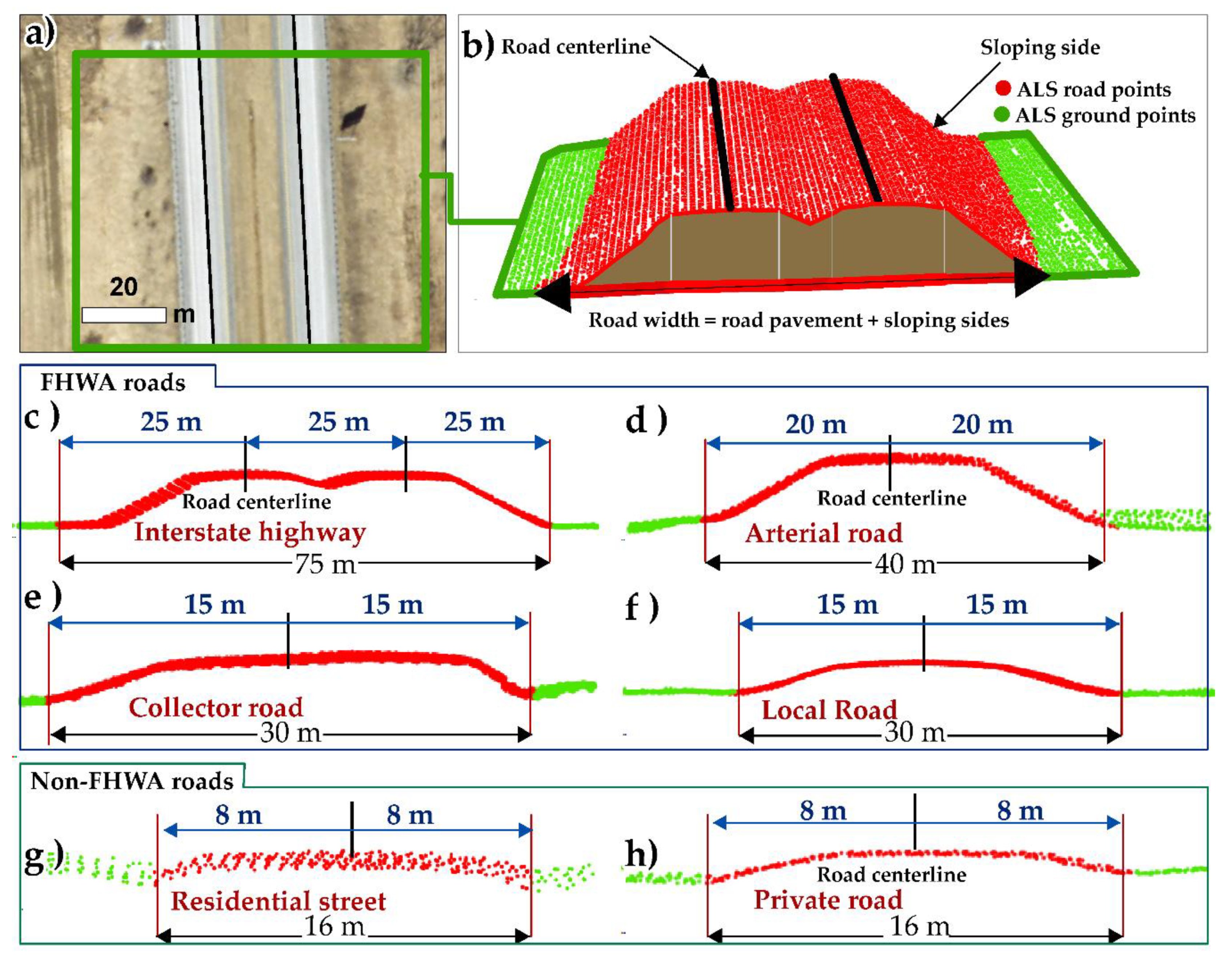
In the context of this paper, a road is comprised of a paved way with sloping sides, as shown by the ALS ground points (Figure 5b). The surface of a road is impervious and it is elevated above the surrounding terrain. Figure 5b shows an example of an ALS point cloud of a road surface with sloping sides (red dots in Figure 5b) from an interstate highway (Figure 5a) in one of our sites. The 5 m wide cross-sections of different road profiles, including FHWA and non-FHWA, are shown in Figure 5c–h, where each profile contains more than 1000 points. It is found that non-FHWA roads (i.e., residential streets and private roads; see Figure 5g,h) were less elevated than FHWA roads (Figure 5c–f), showing that, for both FHWA and non-FHWA, the roads are frequently elevated above neighboring ALS ground points (Figure 5).
The road width (including its sloping sides) of FHWA and non-FHWA roads was estimated from ALS point clouds. To account for the variation in urban and rural environments, the road widths at 15 random locations for each road class were estimated (see Table 2). Out of the 15 observations made, the maximum width value of each road class was considered so that the roads could be removed entirely from the ALS point clouds (see Section 3.2). The road buffer values were calculated from the maximum road widths (Figure 5c–h). A buffer value is simply half of the maximum width of each road class, as shown in Figure 5c–h and estimated buffer values for each functional road class are provided in Table 2.
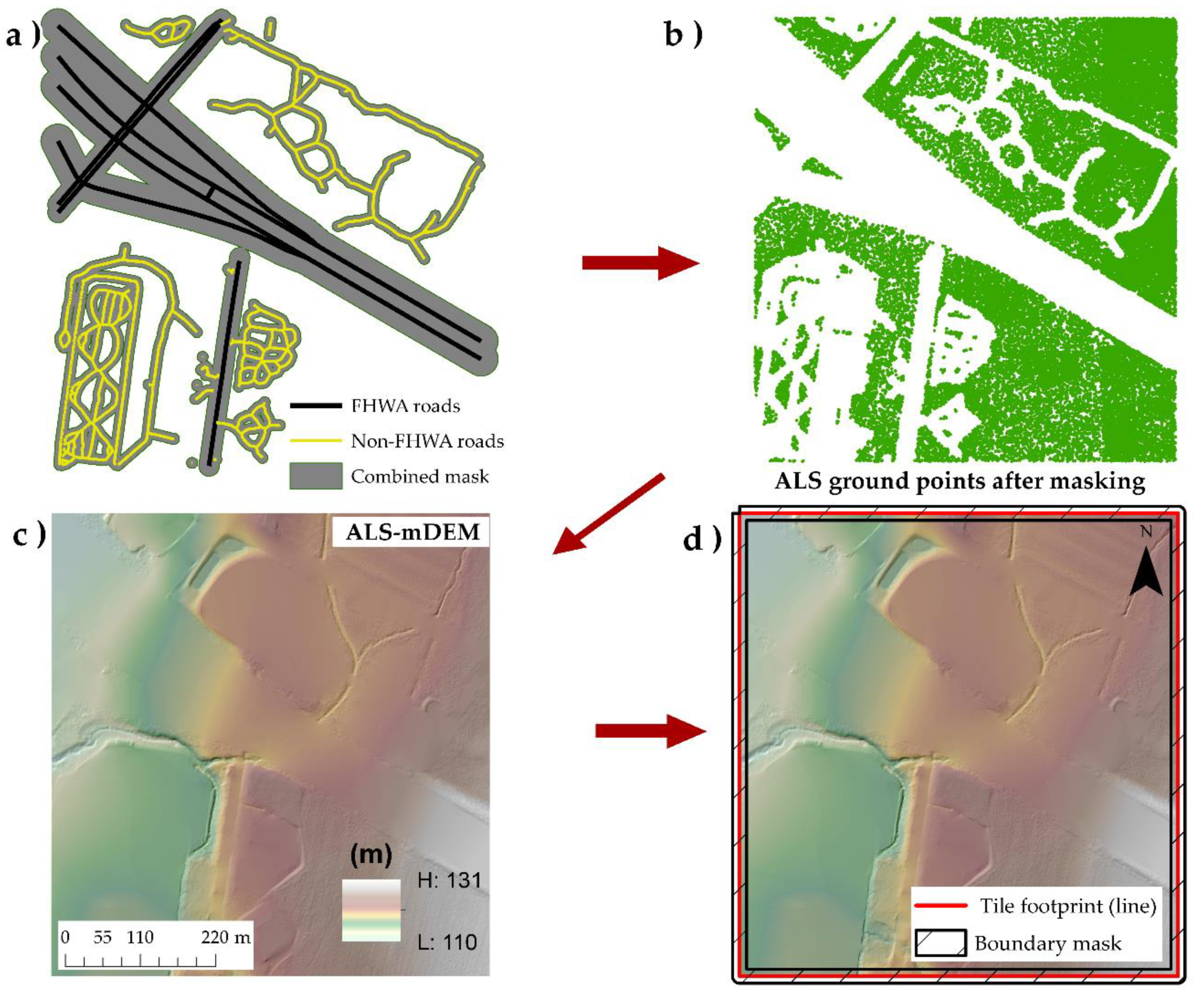
The estimated buffer values were used to place buffers around both sides of FHWA and non-FHWA road centerlines (Figure 3a) according to their road class (Table 2) in order to obtain a combined road mask, as shown in Figure 6a.

3.2. ALS-mDEM Production

As shown in Figure 5, the roads are elevated above their neighboring ALS ground points (green points in Figure 5), leading to the unreliable pathways of watercourses, i.e., DN [21]. Therefore, in the second stage, the ALS ground points of FHWA and non-FHWA roads were removed from each ALS tile (Figure 3b and Figure 6b) using a combined road mask (Figure 3a and Figure 6a). Then, ALS-mDEM tiles were produced from the remaining ALS ground points using NNI at a GSD of 0.5 m (Figure 6c). A GSD of 0.5 m was used to retain most of the topographic information offered by the ALS point clouds at a point density of 2 pt/m2. In the context of automation, NNI does not require any user-defined parameters to find the minimum number of points to be interpolated, e.g., the neighborhood search radius, which makes it the simplest interpolation method [45]. To ensure the NNI interpolated elevation values are consistent between ALS-mDEM tiles, elevation values within a 1 m buffer of the tile boundaries were discarded (Figure 6d). To avoid the data voids at tile boundaries, a 1 m tile boundary overlap was maintained in the data processing stage (Figure 4a,b).

3.3. Candidate DS Mapping

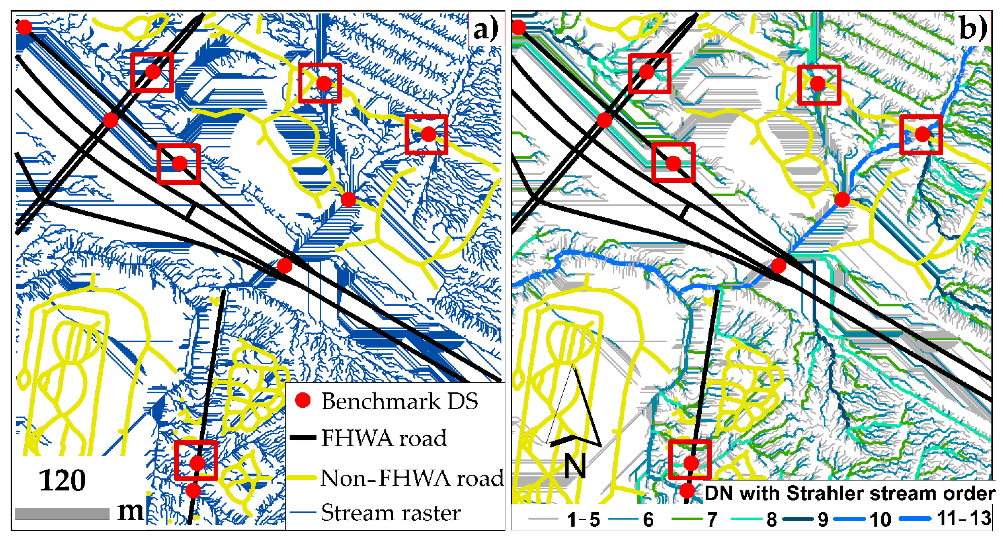
In the third stage, ALS-mDEM tiles were then mosaiced into a single continuous ALS-mDEM using the “Mosaic to New Raster” tool in a ArcGIS Toolbox [46]. Both the real and artificial sink artifacts were removed from ALS-mDEM using the method adopted by Jenson and Dominque [47] (Figure 3c). A sink is defined as a cell or group of cells with all immediate neighboring cells at a higher elevation, which prevents automated DN extraction from ALS-mDEM due to sinks. The stream raster was then generated from the sink-free ALS-mDEM (Figure 7a) using the D8 method [48], followed by assigning Strahler stream orders [49,50] to the stream raster (Figure 3c and Figure 7b).
In the context of automation, no information was gained by plotting the benchmark DS dataset over the stream raster (see red rectangles in Figure 7a). We found that the benchmark DS dataset aligned with streams of higher orders (see red rectangles in Figure 7b) by making the streams of lower orders, e.g., stream orders 1–5, less significant (Figure 7b). Because of this, Strahler stream orders were implemented in DSMA so that different stream order thresholds could be used automatically. Examples of candidate DS obtained after intersecting DNs with stream order thresholds of 6, 7, and 8 are shown in Figure 8a–c, respectively. The stream order thresholds help to discard those streams that are less likely to contain DS (see Figure 8a,b).
Candidate DS (green dots), obtained with a stream order threshold of 7, meaning all streams with stream orders of 7 or higher were intersected with centerlines of FHWA and non-FHWA roads, showed close agreement with the benchmark DS dataset (Figure 8b). A large number of false candidate DS were obtained with the stream order threshold of 6 (green dots within red rectangles in Figure 8a). Several valid candidate DS were omitted at a stream order threshold of 8 (red rectangles in Figure 8c). Therefore, a stream order threshold of 7 was used for mapping DS in Site A (Figure 1a) and Site B (Figure 1b).
The candidate DS enclosed within the area marked with a red rectangle in Figure 8b indicates that a single benchmark DS has several competing candidate DS mapped at a stream order threshold of 7, all of which are considered duplicate DS. To fix duplicate DS, the candidate DS refinement stage was implemented.

3.4. Candidate DS Refinement

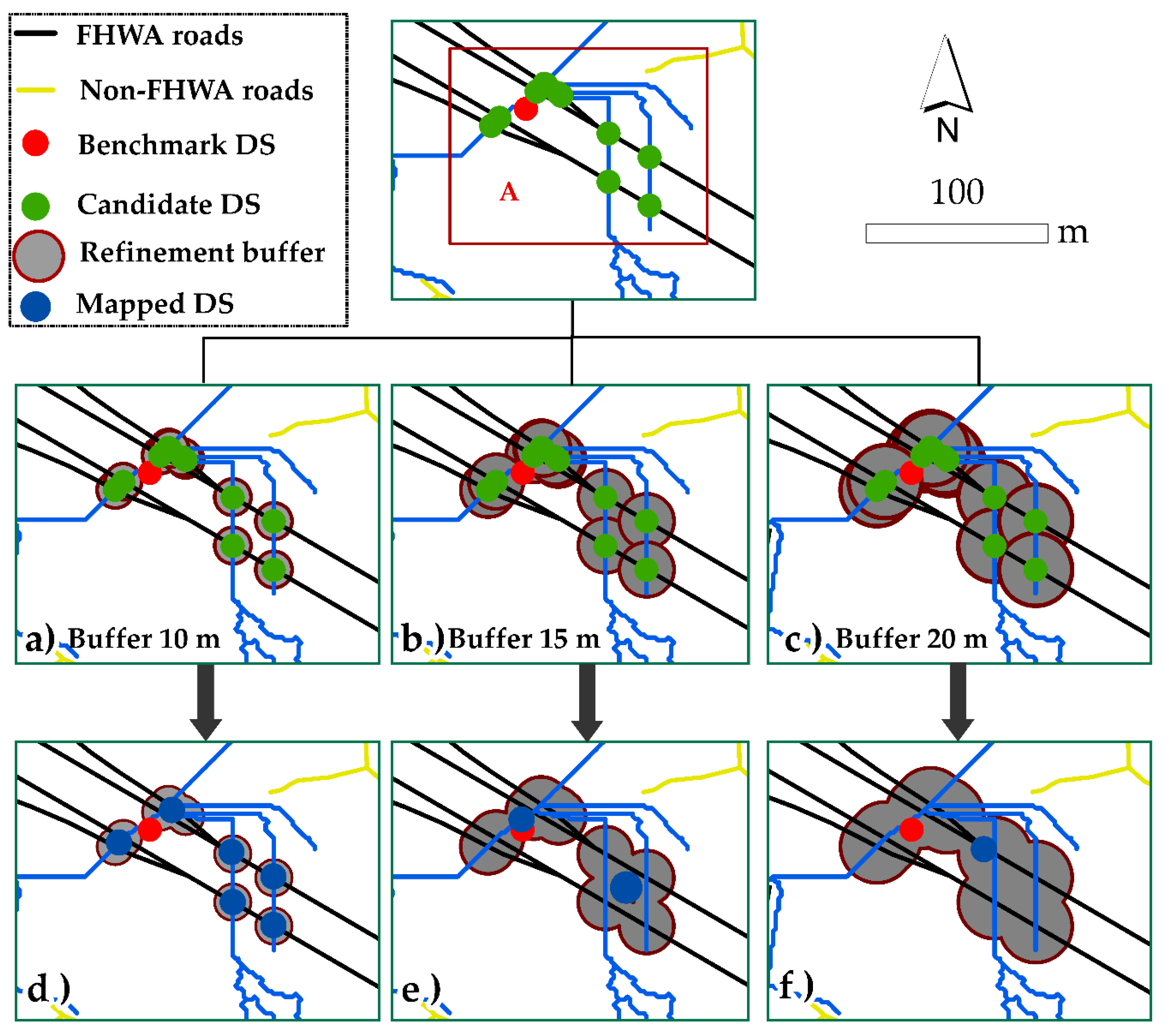
The candidate DS refinement process begins by placing a buffer around each candidate DS (Figure 9a–c). Buffers that overlap with neighboring buffers are clusters of the duplicate DS; therefore, these buffers are merged into a single buffer (Figure 9d–f). All candidates within the merged buffer are later removed (Figure 9d–f). Finally, the centroid of each merged buffer is computed (blue dots in Figure 9d–f), which represents the output of DSMA (see the DSMA workflow in Figure 3d). This is referred to as “mapped DS” in the rest of the article.
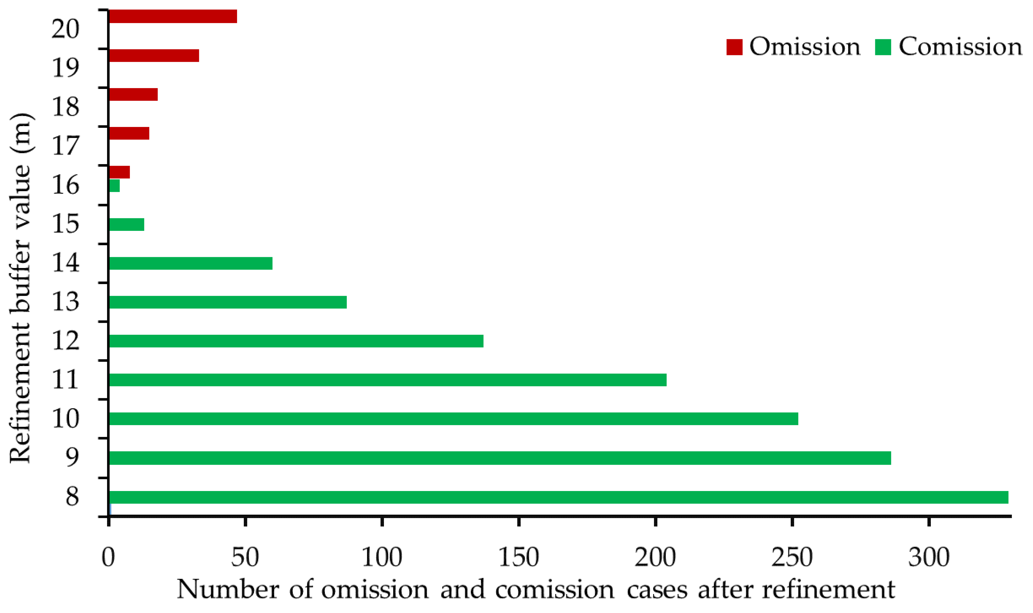
A 15 m refinement buffer is chosen (Figure 9b,e) after assessing a series of buffer values from 8 m to 20 m with an increment of 1 m for each step (Figure 10).
Figure 10 shows that buffer values less than 15 m were less effective at eliminating duplicate DS. See an example case of a buffer value of 10 m in Figure 9a,d and corresponding commission cases caused by duplicate DS in Figure 10. The buffer value of 15 m (Figure 9b) proved to be optimal for removing duplicate DS (Figure 9e), yet does not cause omission cases, i.e., to eliminate valid DS. However, buffer values higher than 15 m proved to be less effective because values higher than 15 m eliminate several valid DS, resulting in omissions (Figure 10).

3.5. Accuracy Assessment

To analyze and quantify the performance of the proposed algorithm along with FHWA and non-FHWA roads of an urban site and a rural site, we undertook positional and prediction accuracy assessments using a benchmark DS dataset (see Section 2.2.4).

3.5.1. Positional Accuracy

A one-to-one correspondence was established between the mapped DS and the benchmark DS, e.g., each mapped DS locates its closest neighboring benchmark DS. A unique ID was generated for each benchmark DS so that one-to-many correspondences could be avoided. The Euclidian distance of the offset ( D p ) was calculated between each mapped DS ( x 1 , y 1 ) and its corresponding benchmark DS ( x 2 , y 2 ) using Equation (1).
D p = ( x 2   x 1 ) 2   +   ( y 2   y 1 ) 2

3.5.2. Prediction Accuracy

The F1-score, which is the harmonic mean of precision (P) and recall (R), was used to assess prediction accuracy. An F1-score near 1 indicates good performance, and values closer to 0 indicate a bad performance. The precision and recall were calculated using Equations (2) and (3), respectively. The F1-score was calculated using Equation (4).
P = N T P / ( N T P + N F P )
R = N T P / ( N T P + N F N )
F 1 - Score   =   2 × P × R / ( P + R )
where N T P is the number of true positive (TP) cases, i.e., the number of correctly mapped DS; N F P is the number of false positive (FP) cases, i.e., the number of false DS mappings; N F N is the number of false negative (FN) cases, i.e., the number of DS that were not mapped by DSMA.

4. Results

The positional accuracies of DSMA are generally similar for the two sites. The median values of D p were 9.03 m and 10.17 m for the urban site and rural site, respectively; the mean values of D p were 13.53 m and 15.82 m for the rural site and urban site, respectively. Detailed statistics regarding the positional accuracies are shown in Table 3.
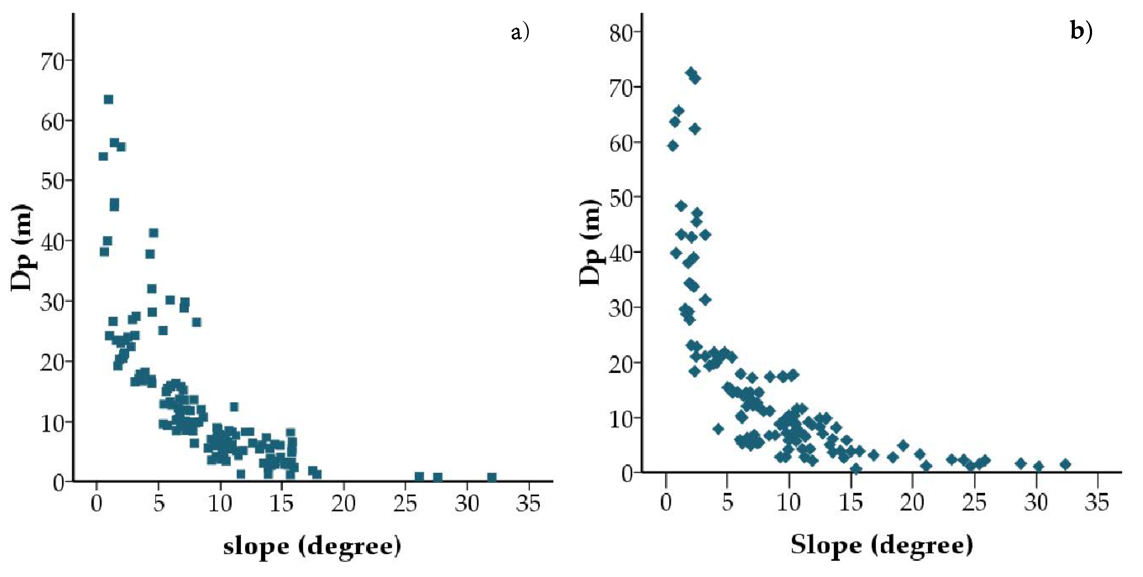
Notable differences were found for the maximum values and the third quartiles. For the urban site, maximum offsets of 63.45 m were found in residential areas; for the rural site, maximum offsets of 72.53 m were found in the Missisquoi River flood plain. This means the maximum D p values of the mapped DS were found in very low topographical relief areas where the slope was approximately 0° (Figure 1c,d). The third quartiles were 17.12 m and 10.17 m for the urban sites and rural sites, respectively.
To further investigate the effect of the topographic slope on the positional accuracy of mapped DS, the maximum slope within a 30 m buffer around each DS was calculated using ALS-mDEM. Scatterplots of the offsets ( D p ) of mapped DS between the maximum slopes of benchmark DS are shown in Figure 11. The relation between the offset and slope can be better visualized by the moving average line (Figure 11). According to the moving average line, when the slope is less than 5 degrees, the offsets are larger than 15 m and 20 m for the urban site (Figure 11a) and rural (Figure 11b) site, respectively.
The prediction accuracies (F1-scores) of DSMA for FHWA roads were 0.87 and 0.94 for the urban site and rural site, respectively (Table 4). The F1-scores for non-FHWA roads were 0.72 and 0.74 for the urban site and rural site, respectively (Table 4).
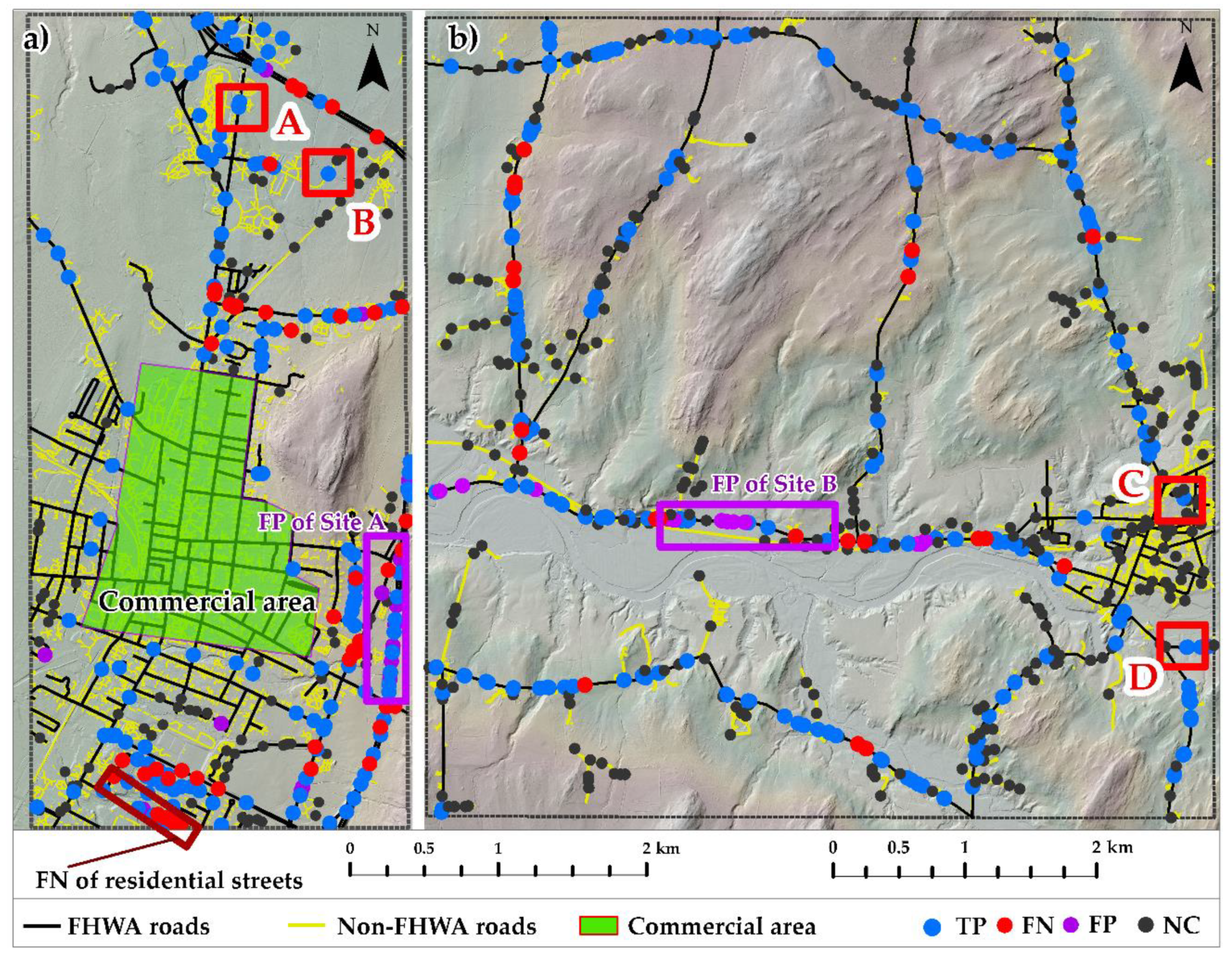
Figure 12 shows the distribution of TP (blue dots), FP (purple dots), and FN (red dots) of mapped DS in the urban site and rural site. A few examples of TPs in cases A, B, C, and D, along with FHWA and non-FHWA roads for the urban and rural site, are marked with red rectangles in Figure 12 and are shown in GE-SV (see Figure 13). The grey dots in Figure 10 denote mapped DS without a corresponding benchmark DS and are herein referred to as “not confirmed” (NC) cases. For the FHWA roads, the number of NC cases ( N N C ) were 12 and 66 for in the urban site and rural site, respectively; for the non-FHWA roads, N N C were 86 and 177 for the urban site and rural site, respectively.

4.1. False Negative Cases

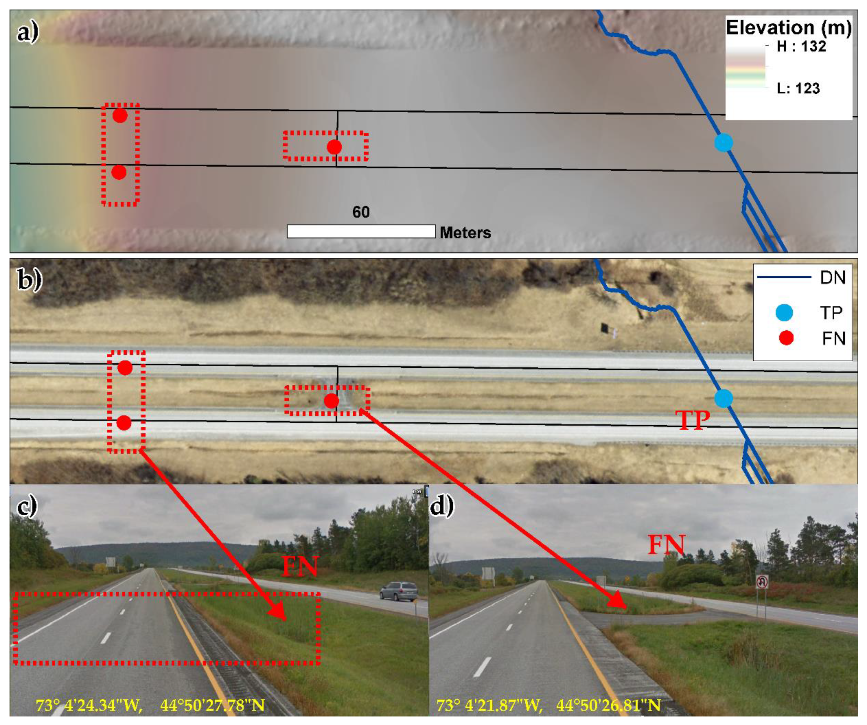
For the urban site, a total of 17 FN cases were found for FHWA roads, and 15 of them were found along the interstate highway. Because the proposed DSMA was devised to extract DN belonging to a stream or a river, it failed to extract DN belonging to the underground highway drainage system. Two FN examples from the urban site (A) interstate highway are shown in Figure 14c,d using GE-SV images. For the rural site, FHWA roads do not contain an interstate highway; therefore, there were less FN (Table 4). The lower recall value observed for FHWA roads of the urban site (A) was due to the underground highway drainage system (Table 4).
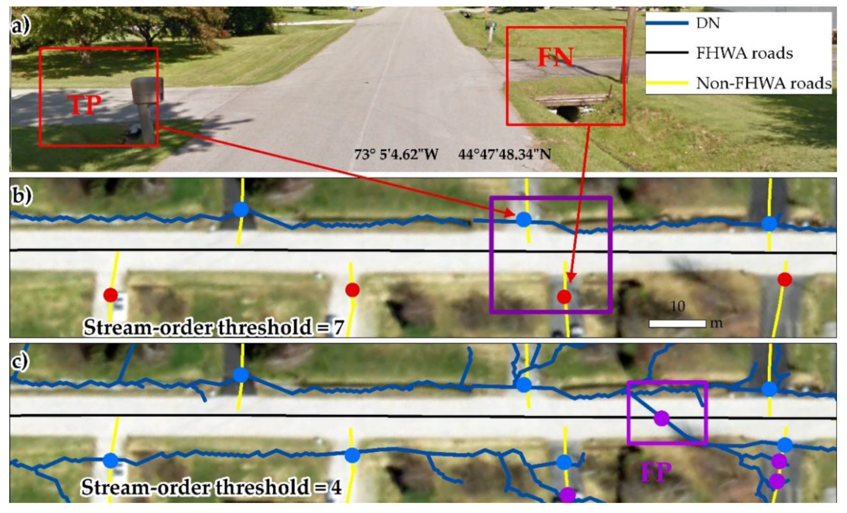
For both the urban site and the rural site, several FN cases were found for the non-FHWA roads (more specifically, residential streets). There were 28 and 14 FN cases for the urban site (A) and rural site (B), respectively. DS of one side of a residential street were mapped, while the other side was missed entirely, as shown in Figure 15a,b.
In the residential area, most of the streams were of a stream order lower than 6. Therefore, at the stream order threshold of 7, lower-order streams were dropped from DN, and DS were not mapped by the DSMA (Figure 15b). By using a lower stream order threshold of 4, these FN cases could be reduced (Figure 15c). This suggests that an adaptive stream order threshold to account for residential areas (vs. agricultural and forest areas) would be useful for processing a large dataset.
The FN of residential streets (Figure 15) caused the lower recall and F1-score values of non-FHWA roads in urban and rural sites, respectively (Table 4).
The rest of the FN cases were randomly found along FHWA and non-FHWA roads of the two sites. Examples of these cases are shown in Figure 16. Figure 16a shows the FN cases where both the DN and centerline of the non-FHWA roads were absent for the extraction of DS (denoted by red dots). Figure 16b shows the FN cases where both DN and the centerline of a non-FHWA road were present, but where they did not intersect to extract a DS (denoted by red dots). Figure 16c shows the FN cases where the extracted DN did not cross the FHWA road for DS extraction (denoted by red dots). Most of these cases are associated with data completeness (e.g., road centerlines of FHWA and non-FHWA roads).

4.2. False Positive Cases

The regions marked with purple rectangles in Figure 12a,b contain most of the FP cases for FHWA roads in the two sites.
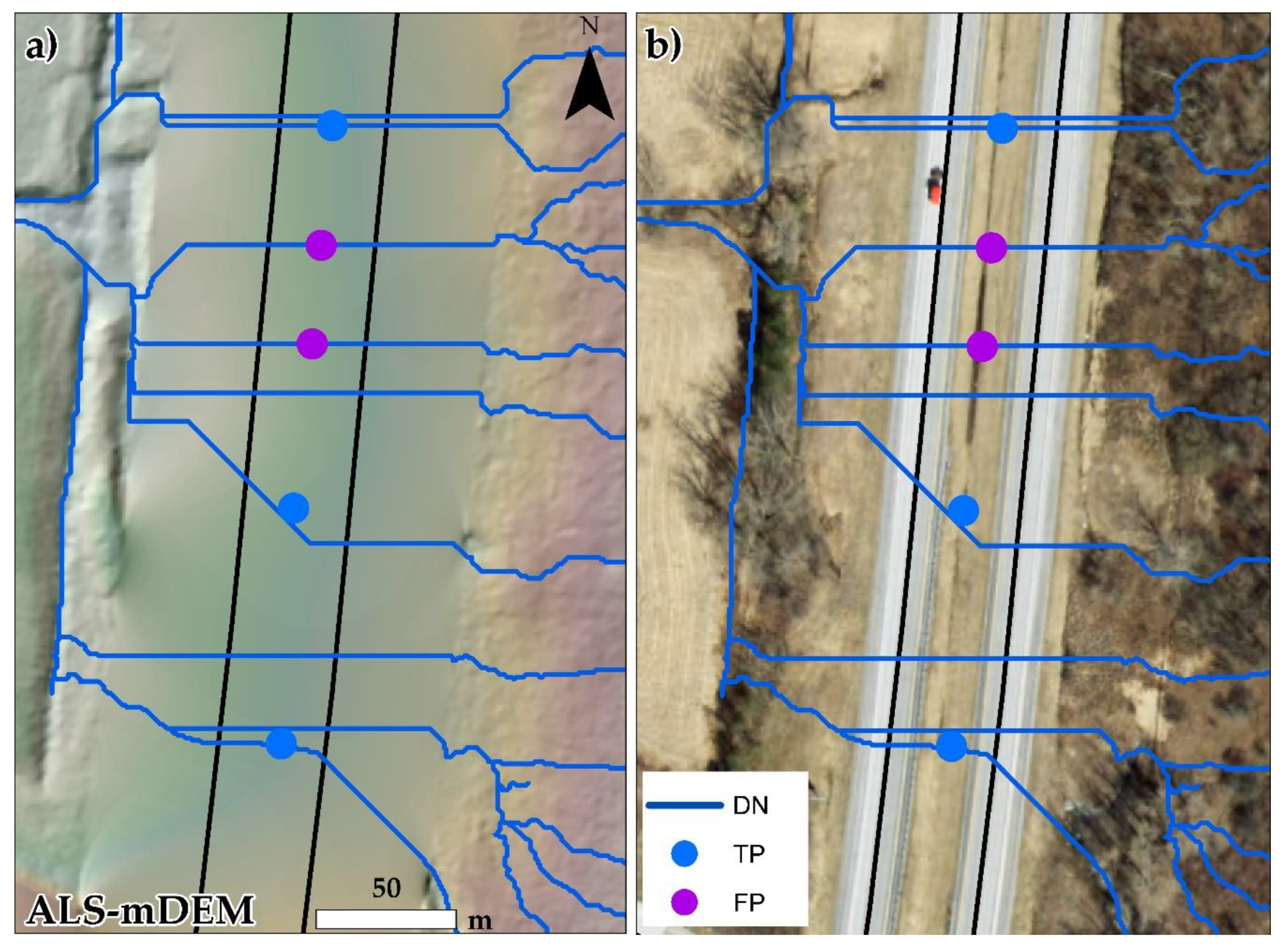
A total of 19 FP cases were found in the urban site and 10 cases of FP cases were found along the FHWA interstate highway (I-89) in the southeast part of the urban site (denoted by the purple rectangle in Figure 12a). These FP cases (purple dots in Figure 17) were due to the presence of some of the DSMA-extracted artificial DN, which intersected with the FHWA road. For fewer locations, road masking caused the removal of some roadside ditches, causing some artificial DN channels in DSMA.
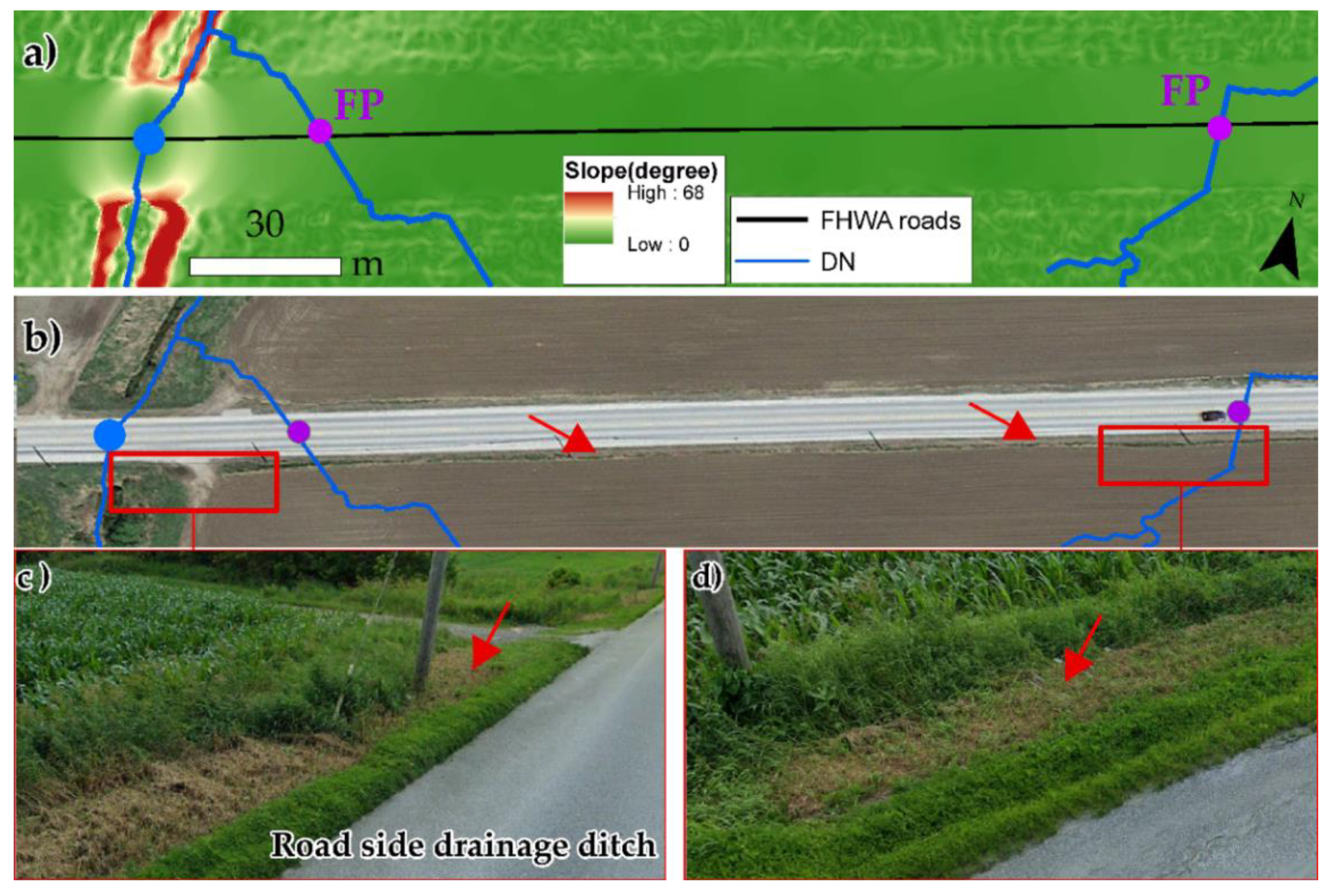
The FP cases in the rural site were frequently found along the FHWA road (the purple rectangle in Figure 12b, with a zoomed-in image shown in Figure 18). Although the FHWA road had drainage ditches along its sides (Figure 18c,d) to carry the watercourse to a nearby stream or river (see Figure 18b–d), they were removed from the ALS-mDEM (Figure 18a) due to the road mask that was implemented in the second stage of DSMA. Thus, an artificial DN was formed, which crossed the FHMA road and led to FP cases due to the absence of drainage ditches in ALS-mDEM.
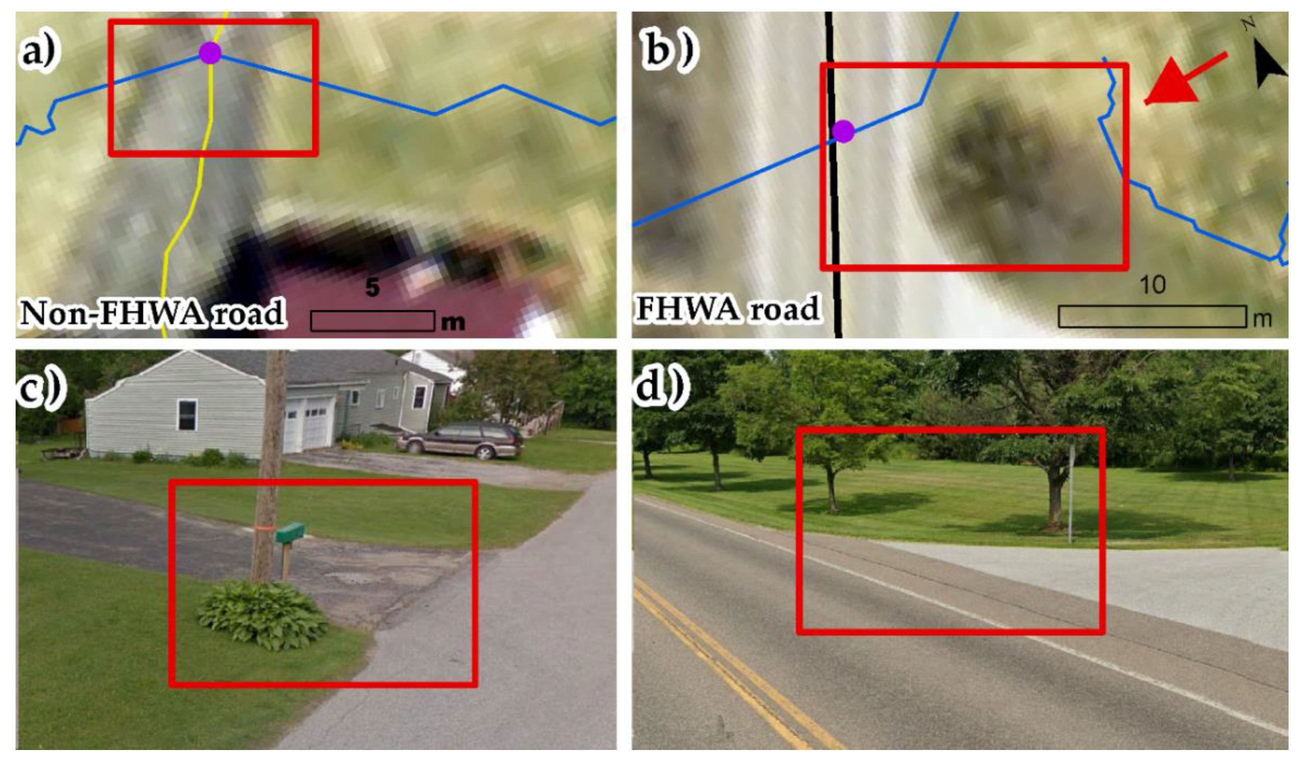
Similar artificial DN, which crossed over the FHWA and non-FHWA roads in the residential areas (Figure 19a,b), were also found in the two sites because the topography of both sides of the roads was removed by the road mask implemented in the second stage of DSMA. There were 8 and 3 FP cases for FHWA and non-FHWA roads, respectively.

5. Discussion

The DSMA is implemented using the model builder in ArcGIS 10.8.1 (https://github.com/Nadeem1geo/Drainage-Structures-Mapping-Algorithm-DSMA-) and tested over an area of 50 km2 (Figure 1) using an Intel Core™ i7-3770K @ 3.5GHz processor with an installed random access memory of 16 gigabytes. The ALS-mDEM was processed at GSD of 0.5 m and a stream order threshold of 7 was set to map DS. The processing times for each module under a different tiling schemes are presented in Table 5.
Table 5 emphasizes the fact that the processing time can be reduced by increasing the tile size. This is because a larger tile size requires reduced iterations to process point clouds, e.g., creating ALS-mDEM tiles and afterwards removing tile boundary artifacts from each ALS-mDEM tile. In the ArcGIS 10.8.1 environment, DSMA can process point cloud tiles with a maximum size of 4 × 4 km because NNI reaches an interpolation limit of a maximum of 15 million points at a point density of 2 pt/m2. For that reason, the tiling scheme was implemented to process massive point clouds by splitting them into manageable tiles (Table 5). Note that the different tiling schemes only affect the overall processing time. The total number of mapped DS remains the same at different tiling schemes because the DSMA mosaics ALS-mDEM tiles into a single continuous ALS-mDEM before mapping DS. The end product for different tiling schemes has always been a single, continuous ALS-mDEM.
The ISA was included to map the DS of non-FHWA roads, e.g., NC cases in both sites (Figure 12a,b). The FHWA roads obtained from government sources do not account for private roads and residential streets as they do not fall under the jurisdiction of the government (i.e., non-FHWA roads); therefore, DS of non-FHWA roads (Table 4) cannot be mapped using FHWA roads only. This feature makes the DSMA robust, as it includes the ISA to map DS placed under non-FHWA roads (Figure 12). The DSMA successfully predicts where a DS is located (TP) or where a DS may possibly be found (NC; black dots in Figure 12).
Certain limitations were found during the DSMA evaluation. First, ground points must be present in the given ALS data as DSMA utilizes ground points only, and intensity information is of no use for DSMA. Automated or semi-automated ground point filtration must be used for un-classified point clouds. This can be achieved using ground point classification algorithms [51]. Despite those limitations, reasonable positional and prediction accuracies were achieved (Table 3 and Table 4) with an F1-score of 0.87 for FHWA urban and 0.92 for FHWA rural, whereas 0.72 was achieved for non-FHWA urban and 0.74 was achieved for non-FHWA rural roads, respectively. In recent times, ALS technology has significantly advanced, acquiring point clouds with higher point-densities and vertical accuracies [29,52]. Therefore, it is believed that the DSMA may show a better performance using more recent ALS data, and this hypothesis will be evaluated in future work. Second, a road mask was an effective approach to eliminate FHWA and non-FHWA roads from ALS ground points. To create an effective road mask from different road classes, buffer values were found manually using ALS ground points (Figure 5 and Table 2). The buffer values given in Table 2 are effective for Vermont, USA. For other regions of the world, buffer values can vary. For that reason, buffer values must be found according to road classes (as designated by DOTs of other states and countries).
In terms of FN, the DSMA is unable to map DS placed within an underground drainage system of an interstate highway (see Figure 14). This is one of the limitations of the DSMA because it is based on the intersection of the road centerlines with a DN from ALS-mDEM. ALS-mDEM-based DN can only be found for surface watercourses (i.e., rivers and streams); therefore, the underground drainage systems of interstates and state highways constitute an exception. At the data end, low quality and incomplete road centerline information can also compromise DS mapping (see Figure 16a,b). DS mapping can be improved by ensuring data quality and consistency issues are solved, as shown in Figure 16. In terms of FP, the algorithm seems to map DS wrongly for streams that are diverted or artificially channeled along roads through drainage ditches in urban and rural areas (Figure 17 and Figure 18). This is because the DSMA attempts to map DS based on the local topography upstream and downstream of a road (see TP of Figure 14a,b, Figure 17a and Figure 18a). For streams that are diverted along an interstate highway or along roads on agricultural land through drainage ditches, the DSMA aims to find the possible location where the stream should cross a road segment based on the local topography of that particular area. In situ, the stream follows the diverted path through drainage ditches that were removed by the second stage of DSMA (see Figure 18a–d), thus causing the false DS mapping for some locations (see FP of Figure 17 and Figure 18).
The DSMA performance was evaluated and quantified for whole-site areas (Figure 1a,b). The evaluation suggests that the overall prediction accuracies have shown improved results for urban areas with a stream order threshold of 4 (Figure 15c). The urban areas contain residential streets where small culverts (Figure 13a,c) are placed over streams with stream order thresholds of 4 or higher (Figure 15a). We already demonstrated that the DSMA prediction accuracy could improve for residential areas by setting a lower stream order threshold of 4 (see Section 4.1, Figure 15c). DSMA is a newly developed algorithm with no counterpart in the present market and provides substantial new information on this topic; therefore, a comparison with a state-of-the-art method was not possible. Instead, we assessed the DSMA performance compared to a benchmark DS dataset (see Section 2.2.4) gathered and augmented from reliable sources.
The use of ALS topographic data in geomorphology, hydrology, and flood inundation modeling has increased substantially in recent years [11,16]. For several other studies, detailed DS datasets were either absent or manually incorporated into the research work carried out [15,17,18,19,53]. With wide-area ALS data availability in many countries, e.g., 3D elevation programs (3DEPs) [54], the DSMA is a useful tool to provide extensive DS datasets over wide areas, as evaluated in this study.

6. Conclusions

This study proposed a DSMA using ALS point clouds and road centerline information and investigated its performance over an urban site and a rural site of 50 km2 in Vermont, USA. Due to the presence of elevated roads in ALS-DEM, extracting DN from ALS-DEM becomes problematic. For that reason, ALS-mDEM is introduced in this study. Prior to the creation of ALS-mDEM, ground points within a combined road mask, which was created from FHWA and non-FHWA road centerlines, were removed. The DN, derived from the ALS-mDEM, was then intersected with FHWA and non-FHWA road centerlines to obtain candidate DS. In order to remove duplicate candidate DS, different buffers were experimented with to refine the candidate DS using proximity analysis, which resulted in a 15 m refinement buffer for the obtained mapped DS.
The DSMA evaluation is based on a benchmark DS dataset acquired from VTrans and further augmented using GE-SV by the authors. First, we calculated the one-to-one Euclidean distances of mapped DS compared to the benchmark DS to quantify their positional accuracies. The mean positional accuracies were 13.5 m and 15. 8 m for the urban and rural sites, respectively, whereas the median values were 9.03 m and 10.07 m for the urban and the rural sites, respectively. The maximum Euclidean distances of 72.53 and 63.45 m were observed for the urban and the rural sites, respectively, when the topographic slope was approximately 0°. We concluded that the slope is an important factor in determining the positional accuracies of the DSMA.
Second, prediction accuracies were assessed using F1-scores. F1-scores indicated subtle differences among FHWA urban (0.87) and FHWA rural (0.92) roads. Similarly, non-FHWA urban (0.72) and non-FHWA rural (0.74) roads indicated similar trends, but lower prediction accuracies were found compared to FHWA roads.
The proposed DSMA was designed to map DS placed over rivers and streams; therefore, DS placed within highway drainage systems, which connect to nearby streams, were missed by DSMA.
We used modest hardware and software resources that are available to most researchers. The DSMA processed ALS point clouds covering 50 km2 in 122 min with an Intel Core™ i7-3770K @ 3.5GHz processor with 16GB of RAM (Random Access Memory). Our evaluation concludes that the proposed DSMA is also capable of processing ALS point clouds over larger areas to uniformly map DS on FHWA and non-FHWA roads.

Author Contributions

Conceptualization, C.-K.W. and N.F.; methodology, N.F. and C.-K.W.; software, N.F. and C.-K.W.; formal analysis, N.F.; writing—original draft preparation, N.F. and C.-K.W.; writing—review and editing, C.-K.W. and N.F.; visualization, N.F. and C.-K.W.; supervision, C.-K.W. All authors have read and agreed to the published version of the manuscript.

Funding

This research was funded by the Ministry of Science and Technology (MOST) of Taiwan, under the grant number MOST 108-2621-M-006-006.

Institutional Review Board Statement

Not applicable.

Informed Consent Statement

Not applicable.

Data Availability Statement

The data that support the findings of this study are available from the corresponding author upon reasonable request.

Acknowledgments

The authors thank U.S. Geological Survey for providing ALS point clouds through OpenTopography. We thank The Vermont Agency of Transportation for providing benchmark DS dataset. We also thank Vermont Center for Geographic Information for providing road centerline information, impervious surface area, and Orthophotos. We are indebted to the anonymous reviewers for their careful reading of the manuscript and their valuable suggestions.

Conflicts of Interest

The authors declare no conflict of interest.

References

  1. Heidemann, H.K. Lidar Base Specification; 2328-7055; US Geological Survey: Reston, VA, USA, 2012.
  2. Meijer, J.R.; Huijbregts, M.A.J.; Schotten, K.C.G.J.; Schipper, A.M. Global patterns of current and future road infrastructure. Environ. Res. Lett. 2018, 13, 064006. [Google Scholar] [CrossRef] [Green Version]
  3. Koks, E.E.; Rozenberg, J.; Zorn, C.; Tariverdi, M.; Vousdoukas, M.; Fraser, S.A.; Hall, J.W.; Hallegatte, S. A global multi-hazard risk analysis of road and railway infrastructure assets. Nat. Commun. 2019, 10, 1–11. [Google Scholar] [CrossRef] [PubMed] [Green Version]
  4. Pedrozo-Acuña, A.; Moreno, G.; Mejía-Estrada, P.; Paredes-Victoria, P.; Breña-Naranjo, J.; Meza, C. Integrated approach to determine highway flooding and critical points of drainage. Transp. Res. Part D Transp. Environ. 2017, 50, 182–191. [Google Scholar] [CrossRef]
  5. Chen, A.S.; Hsu, M.-H.; Huang, C.-J.; Lien, W.-Y. Analysis of the Sanchung inundation during Typhoon Aere, 2004. Nat. Hazards 2010, 56, 59–79. [Google Scholar] [CrossRef]
  6. Lwin, M.M.; Yen, W.P.; Shen, J.J. Effects of Hurricane Katrina on the Performance of U.S. Highway Bridges. J. Perform. Constr. Facil. 2014, 28, 40–48. [Google Scholar] [CrossRef]
  7. Bhattachar, D.V.; Najafi, M.; Salem, O.; Funkhouser, P.; Salman, B. Development of an Asset Management Framework for Culvert Inventory and Inspection. In Pipelines 2007: Advances and Experiences with Trenchless Pipeline Projects, Proceedings of the International Conference on Pipeline Engineering and Construction, Boston, MA, USA, 8–11 July 2007; American Society of Civil Engineers: Reston, VA, USA, 2007; pp. 1–11. [Google Scholar] [CrossRef]
  8. Venner, M.; Berger, L. Culvert Management Case Studies: Vermont, Oregon, Ohio and Los Angeles County; United States Federal Highway Administration: Washington, DC, USA, 2014.
  9. Najafi, M.; Bhattachar, D.V. Development of a culvert inventory and inspection framework for asset management of road structures. J. King Saud Univ. Sci. 2011, 23, 243–254. [Google Scholar] [CrossRef] [Green Version]
  10. Meegoda, J.; Juliano, T.; Potts, L.; Tang, C.; Marhaba, T. Implementation of a drainage information, analysis and management system. J. Traffic Transp. Eng. Eng. Ed. 2017, 4, 165–177. [Google Scholar] [CrossRef]
  11. Tarolli, P.; Sofia, G. Human topographic signatures and derived geomorphic processes across landscapes. Geomorphology 2016, 255, 140–161. [Google Scholar] [CrossRef] [Green Version]
  12. Dutta, D.; Teng, J.; Vaze, J.; Lerat, J.; Hughes, J.; Marvanek, S. Storage-based approaches to build floodplain inundation modelling capability in river system models for water resources planning and accounting. J. Hydrol. 2013, 504, 12–28. [Google Scholar] [CrossRef]
  13. Barber, C.P.; Shortridge, A. Lidar Elevation Data for Surface Hydrologic Modeling: Resolution and Representation Issues. Cartogr. Geogr. Inf. Sci. 2005, 32, 401–410. [Google Scholar] [CrossRef]
  14. Munoz, D.H.; Constantinescu, G. A fully 3-D numerical model to predict flood wave propagation and assess efficiency of flood protection measures. Adv. Water Resour. 2018, 122, 148–165. [Google Scholar] [CrossRef]
  15. Liu, Z.; Merwade, V. Accounting for model structure, parameter and input forcing uncertainty in flood inundation modeling using Bayesian model averaging. J. Hydrol. 2018, 565, 138–149. [Google Scholar] [CrossRef]
  16. Webster, T.L.; Forbes, D.L.; MacKinnon, E.; Roberts, D. Flood-risk mapping for storm-surge events and sea-level rise using lidar for southeast New Brunswick. Can. J. Remote Sens. 2006, 32, 194–211. [Google Scholar] [CrossRef]
  17. Pinos, J.; Timbe, L. Performance assessment of two-dimensional hydraulic models for generation of flood inundation maps in mountain river basins. Water Sci. Eng. 2019, 12, 11–18. [Google Scholar] [CrossRef]
  18. Li, R.; Tang, Z.; Li, X.; Winter, J. Drainage structure datasets and effects on LiDAR-Derived surface flow modeling. ISPRS Int. J. Geo-Inf. 2013, 2, 1136–1152. [Google Scholar] [CrossRef]
  19. Arendt, R.; Faulstich, L.; Jüpner, R.; Assmann, A.; Lengricht, J.; Kavishe, F.; Schulte, A. GNSS mobile road dam surveying for TanDEM-X correction to improve the database for floodwater modeling in northern Namibia. Environ. Earth Sci. 2020, 79, 1–15. [Google Scholar] [CrossRef]
  20. Bryndal, T.; Kroczak, R. Reconstruction and characterization of the surface drainage system functioning during extreme rainfall: The analysis with use of the ALS-LIDAR data—The case study in two small flysch catchments (Outer Carpathian, Poland). Environ. Earth Sci. 2019, 78, 215. [Google Scholar] [CrossRef] [Green Version]
  21. Poppenga, S.K.; Worstell, B.B. Hydrologic Connectivity: Quantitative Assessments of Hydrologic-Enforced Drainage Structures in an Elevation Model. J. Coast. Res. 2016, 76, 90–106. [Google Scholar] [CrossRef] [Green Version]
  22. Persendt, F.C.; Gomez, C. Assessment of drainage network extractions in a low-relief area of the Cuvelai Basin (Namibia) from multiple sources: LiDAR, topographic maps, and digital aerial orthophotographs. Geomorphology 2016, 260, 32–50. [Google Scholar] [CrossRef] [Green Version]
  23. Lidberg, W.; Nilsson, M.; Lundmark, T.; Ågren, A.M. Evaluating preprocessing methods of digital elevation models for hydrological modelling. Hydrol. Process. 2017, 31, 4660–4668. [Google Scholar] [CrossRef] [Green Version]
  24. Wall, J.; Doctor, D.; Terziotti, S. A Semi-automated Tool for Reducing the Creation of False Closed Depressions from a Filled LIDAR-derived Digital Elevation Model. In Sinkholes and the Engineering and Environmental Impacts of Karst, Proceedings of the Fourteenth Multidisciplinary Conference, Tampa, FL, USA, 10 October 2015; Scholar Commons: Tampa, FL, USA, 2015; pp. 255–262. [Google Scholar]
  25. Poppenga, S.K.; Gesch, D.B.; Worstell, B.B. Hydrography Change Detection: The Usefulness of Surface Channels Derived From LiDAR DEMs for Updating Mapped Hydrography. J. Am. Water Resour. Assoc. 2013, 49, 371–389. [Google Scholar] [CrossRef]
  26. Douglas, R.A.; Cochrane, H. Where Have All the Culverts Gone? Int. J. For. Eng. 2001, 12, 79–81. [Google Scholar] [CrossRef]
  27. Wu, T.; Li, J.; Li, T.; Sivakumar, B.; Zhang, G.; Wang, G. High-efficient extraction of drainage networks from digital elevation models constrained by enhanced flow enforcement from known river maps. Geomorphology 2019, 340, 184–201. [Google Scholar] [CrossRef]
  28. Carter, W.E.; Shrestha, R.L.; Slatton, K.C. Geodetic laser scanning. Phys. Today 2007, 60, 41. [Google Scholar] [CrossRef]
  29. Soilán, M.; Truong-Hong, L.; Riveiro, B.; Laefer, D. Automatic extraction of road features in urban environments using dense ALS data. Int. J. Appl. Earth Obs. Geoinf. 2018, 64, 226–236. [Google Scholar] [CrossRef]
  30. Roelens, J.; Rosier, I.; Dondeyne, S.; Van Orshoven, J.; Diels, J. Extracting drainage networks and their connectivity using LiDAR data. Hydrol. Process. 2018, 32, 1026–1037. [Google Scholar] [CrossRef]
  31. Amatya, D.; Trettin, C.; Panda, S.; Ssegane, H. Application of LiDAR data for hydrologic assessments of low-gradient coastal watershed drainage characteristics. J. Geogr. Inf. Syst. 2013, 5, 175–191. [Google Scholar] [CrossRef] [Green Version]
  32. DEMs, H.L. Hydrologic Enforcement of Lidar DEMs; U.S. Geological Survey: Reston, VA, USA, 2014.
  33. University of Vermont Spatial Analysis Laboratory. Impervious Surfaces for the the NY and VT Portions of the Lake Champlain Basin. 2011. Available online: https://maps.vcgi.vermont.gov/gisdata/metadata/LandLandcov_IMPERVLCB2011.htm (accessed on 28 March 2020).
  34. Krishnan, S.; Crosby, C.; Nandigam, V.; Phan, M.; Cowart, C.; Baru, C.; Arrowsmith, R. OpenTopography: A services oriented architecture for community access to LIDAR topography. In Proceedings of the 2nd International Conference on Computing for Geospatial Research & Applications, Washington, DC, USA, 23–25 May 2011; p. 7. [Google Scholar]
  35. Portal, V.O.G. VT Road Centerline. Available online: http://geodata.vermont.gov/datasets/1dee5cb935894f9abe1b8e7ccec1253e_39 (accessed on 15 July 2019).
  36. Dong, J.-X.; Cheng, T.; Xu, J.; Wu, J. Quantitative assessment of urban road network hierarchy planning. Town Plan. Rev. 2013, 84, 467–494. [Google Scholar] [CrossRef]
  37. Vermont Center for Geographic Information. Statewide High-Resolution Vermont Land Cover Data Now Available. Available online: https://geodata.vermont.gov/pages/land-cover#datasets (accessed on 18 August 2019).
  38. Weng, Q. Remote sensing of impervious surfaces in the urban areas: Requirements, methods, and trends. Remote Sens. Environ. 2012, 117, 34–49. [Google Scholar] [CrossRef]
  39. Schaefer, E.I.; Pelletier, J.D. An algorithm to reduce a river network or other graph-like polygon to a set of lines. Comput. Geosci. 2020, 104554. [Google Scholar] [CrossRef]
  40. Vermont Agency of Transportation. The Vermont Online Bridge and Culvert Inventory Tool “VOBCIT”. Available online: https://vtculverts.org/ (accessed on 11 November 2019).
  41. Anguelov, D.; Dulong, C.; Filip, D.; Frueh, C.; Lafon, S.; Lyon, R.; Ogale, A.; Vincent, L.; Weaver, J. Google street view: Capturing the world at street level. Computer 2010, 43, 32–38. [Google Scholar] [CrossRef]
  42. Vermont Center for Geographic Information. Vermont Imagery Program (VIP). Available online: https://geodata.vermont.gov/pages/imagery (accessed on 11 November 2019).
  43. Esri. Natural Neighbor. Available online: https://desktop.arcgis.com/en/arcmap/10.3/tools/spatial-analyst-toolbox/natural-neighbor.htm (accessed on 24 March 2020).
  44. Roussel, J.-R.; Auty, D.; Coops, N.C.; Tompalski, P.; Goodbody, T.R.; Meador, A.S.; Bourdon, J.-F.; de Boissieu, F.; Achim, A. lidR: An R package for analysis of Airborne Laser Scanning (ALS) data. Remote Sens. Environ. 2020, 251, 112061. [Google Scholar] [CrossRef]
  45. Cățeanu, M.; Ciubotaru, A. Accuracy of Ground Surface Interpolation from Airborne Laser Scanning (ALS) Data in Dense Forest Cover. ISPRS Int. J. Geo-Inf. 2020, 9, 224. [Google Scholar] [CrossRef] [Green Version]
  46. Hoover, P.L.B.D. A Seamless, High-Resolution, Coastal Digital Elevation Model (Dem) for Southern California; U.S. Geological Survey: Reston, VA, USA, 2009.
  47. Jenson, S.K.; Domingue, J.O. Extracting topographic structure from digital elevation data for geographic information system analysis. Photogramm. Eng. Remote Sens. 1988, 54, 1593–1600. [Google Scholar]
  48. O’Callaghan, J.F.; Mark, D.M. The extraction of drainage networks from digital elevation data. Comp. Vis. Graph. Image Process. 1984, 28, 323–344. [Google Scholar] [CrossRef]
  49. Shreve, R.L. Statistical law of stream numbers. J. Geol. 1966, 74, 17–37. [Google Scholar] [CrossRef]
  50. Scheidegger, A.E. The algebra of stream-order numbers. U. S. Geol. Surv. Prof. Pap. 1965, 525, 187–189. [Google Scholar]
  51. Ni, H.; Lin, X.; Zhang, J. Classification of ALS point cloud with improved point cloud segmentation and random forests. Remote Sens. 2017, 9, 288. [Google Scholar] [CrossRef] [Green Version]
  52. He, Y.; Song, Z.; Liu, Z. Updating highway asset inventory using airborne LiDAR. Measurement 2017, 104, 132–141. [Google Scholar] [CrossRef]
  53. Jafarzadegan, K.; Merwade, V. A DEM-based approach for large-scale floodplain mapping in ungauged watersheds. J. Hydrol. 2017, 550, 650–662. [Google Scholar] [CrossRef]
  54. Thatcher, C.A.; Lukas, V.; Stoker, J.M. The 3D Elevation Program and Energy for the Nation; U.S. Geological Survey: Reston, VA, USA, 2020; p. 2.
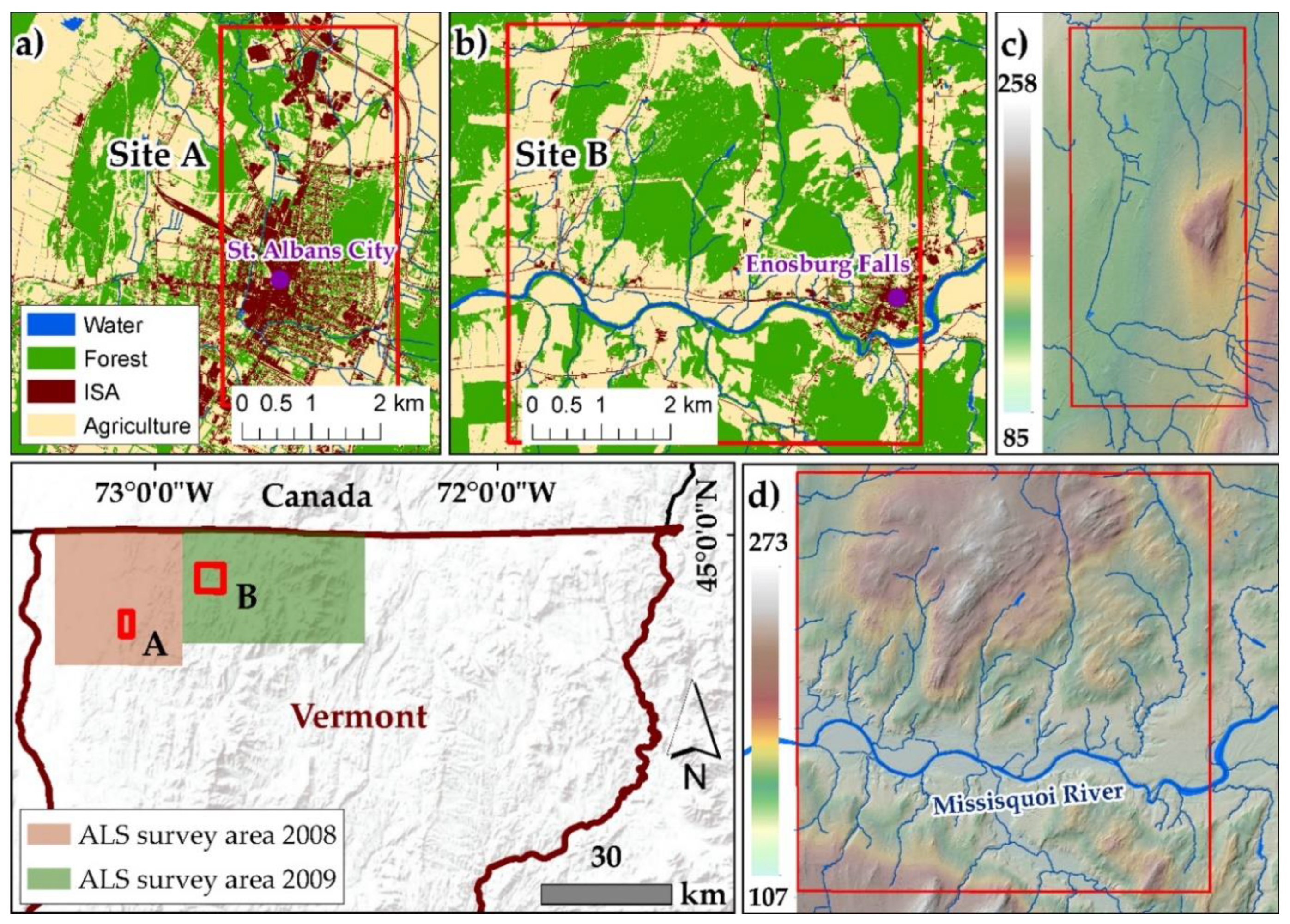
Figure 1. Regional context of Site A and Site B in northern Vermont, USA. The land-use and land-cover of (a) Site A, and (b) Site B. (c) Airborne laser scanning (ALS) survey area of Site A (2008). (d) ALS survey area of Site B (2009).
Remotesensing 13 00463 g001
Figure 2. Benchmark DS dataset of (a) Site A—urban, and (b) Site B—rural. (ce) Examples of augmented and Vermont agency of transportation (VTrans) DS are shown with orthophotos and Google Earth Street View (GE-SV) images.
Remotesensing 13 00463 g002
Figure 3. The four-stage workflow of the proposed DS mapping algorithm (DSMA).
Remotesensing 13 00463 g003
Figure 4. (a) Tiled ALS ground points. (b) Natural neighbor interpolation (NNI) of ALS ground points.
Remotesensing 13 00463 g004
Figure 5. The process of obtaining road widths from ALS point clouds. (a) Part of an interstate highway of Site A, as shown in the orthophoto. (b) Interstate highway width, as seen in ALS point clouds. The maximum estimated road widths from ALS ground points, as shown in (ch) and corresponding buffer values for different road classes of Federal Highway Administration (FHWA) and non-FHWA roads.
Remotesensing 13 00463 g005
Figure 6. ALS-modified digital elevation model (mDEM) production. (a) A combined road mask. (b) ALS point clouds without FHWA and non-FHWA roads. (c) ALS-mDEM. (d) Tile footprint and boundary mask to remove tile boundary artifacts.
Remotesensing 13 00463 g006
Figure 7. (a) Stream raster obtained from ALS-mDEM using D8 method. (b) DN obtained after assigning Strahler stream orders to stream raster.
Remotesensing 13 00463 g007
Figure 8. Candidate DS mapped by intersecting FHWA and non-FHWA roads with DNs at different stream order thresholds. Candidate DS mapped with DN at stream order thresholds of (a) 6, (b) 7, and (c) 8.
Remotesensing 13 00463 g008
Figure 9. Refining process to remove duplicate candidate DS. Examples of refinement buffer values of (a) 10 m, (b) 15 m, and (c) 20 m were tested for area A of Figure 8b.
Remotesensing 13 00463 g009
Figure 10. Refining process to remove duplicate candidate DS using different refinement buffer values.
Remotesensing 13 00463 g010
Figure 11. Scatterplots of topographical relief versus offset D p of mapped DS for (a) Site A, urban, and (b) Site B, rural.
Remotesensing 13 00463 g011
Figure 12. The true positive (TP) (blue dots), false negative (FN) (red dots), false positive (FP) (purple dots), and not confirmed (NC) (black dots) cases for two sites. (a) Site A—urban. (b) Site B—rural. FP areas of Site A and Site B are marked with indigo rectangles and the FN of the residential street is marked with red rectangles.
Remotesensing 13 00463 g012
Figure 13. Examples of cases of TP for FHWA and non-FHWA roads in urban and rural sites. (a) DS of non-FHWA road, urban. (b) DS of FHWA road, urban. (c) DS of non-FHWA road, rural. (d) DS of FHWA road, rural.
Remotesensing 13 00463 g013
Figure 14. Examples of FN (red dots) and TP (blue dots) mapped DS for an interstate highway. (a) TP and FN are displayed over an ALS-mDEM. (b) TP and FN shown on the orthophoto. (c,d) are culverts placed within a highway underground drainage system, as seen in GE-SV.
Remotesensing 13 00463 g014
Figure 15. Examples of FN (red dots) and TP (blue dots) of mapped DS for residential streets. (a) DS on both sides of the residential street as shown by GE-SV. (b) TP and FN cases for residential streets at a stream order threshold of 7. (c) TP and FP (purple dots) at a stream order threshold of 4.
Remotesensing 13 00463 g015
Figure 16. Examples of FN cases (red dots) that were randomly found for the two sites. (a) Both DN and the centerline of a non-FHWA road were absent. (b) Extracted DN does not intersect the centerline of the non-FHWA road. (c) Extracted DN does not cross the FHWA road.
Remotesensing 13 00463 g016
Figure 17. Examples of FP cases on an FHWA interstate highway in the urban site (denoted by the purple rectangle in Figure 11a). (a) TP (blue dots) and FP (purple dots) cases are overlaid on the ALS-mDEM. (b) TP and FP cases are overlaid on the orthophoto.
Remotesensing 13 00463 g017
Figure 18. Examples of FP cases on an FHWA road in the rural site (denoted by the purple rectangle in Figure 11b). (a) FP cases are overlaid on a slope map derived from ALS-mDEM. (b) FP cases are overlaid on an orthophoto. (c,d) show drainage ditches, as seen in GE-SV for FHWA roads.
Remotesensing 13 00463 g018
Figure 19. Typical examples of FP in residential areas. (a) Non-FHWA road artificial DN. (b) FHWA road artificial DN. (c,d) show GE-SV images of artificial DN cases.
Remotesensing 13 00463 g019
Table 1. The number of mapped benchmark drainage structures (DS) for two sites.
Study SitesVTransGE-SVTotal
Site A—Urban13948187
Site B—Rural14818166
Table 2. Estimated road widths and buffer values for FHWA and non-FHWA roads from ALS ground points.
ClassTotal ObservationsWidth Range (m)Buffer (m)
Interstate Highway1542–5025
Arterial Road1530–4020
Collector Road1525–30 15
Local Road1520–3015
Non-FHWA roads155–16 8
Table 3. The positional accuracy of mapped DS for two sites. All units are meters.
Min1st QuartileMedian3rd QuartileMaxMean
Urban Site A0.635.369.0317.1263.4513.53
Rural Site B0.655.7110.1710.1772.5315.82
Table 4. Summary of prediction accuracy for two sites.
Road Type N T P N F N N F P F1-ScorePR N N C
Urban
Site A
FHWA roads9417120.870.890.8512
Non-FHWA roads463070.720.870.6186
Rural
Site B
FHWA roads108690.940.920.9566
Non-FHWA roads271540.740.870.64177
Table 5. The DSMA processing time for each stage with different ALS tiling schemes.
Tile SettingsProcessing Time in Each Stage
Area
km2
Tile Size
km
Total TilesData PreparationALS-mDEMCandidate DS MappingCandidate DS RefinementTotal
50 km21 × 14915461907258
2 × 21215261237171
4 × 431515857122
Note: processing time is given in minutes.
Publisher’s Note: MDPI stays neutral with regard to jurisdictional claims in published maps and institutional affiliations.