Abstract
Preliminary analysis of an archaeological site requires the acquisition of information by several diverse diagnostic techniques. Remote sensing plays an important role especially in spatially extended and not easily accessible sites for the purposes of preventive and rescue archaeology, landscape archaeology, and intervention planning. In this paper, we present a case study of a detailed topographic survey based on a light detection and ranging (LiDAR) sensor carried by an unmanned aerial vehicle (UAV; also known as drone). The high-resolution digital terrain model, obtained from the cloud of points automatically labeled as ground, was searched exhaustively by an expert operator looking for entrances to prehistoric hypogea. The study documents the usefulness of such a technique to reveal anthropogenic structures hidden by vegetation and perform fast topographic documentation of the ground surface.
1. Introduction
The initial job of archaeological intervention on a not previously studied or only partially known site requires a preliminary analysis based on the interdisciplinary use of different diagnostic techniques [1] to identify detectable indicators or anomalies connected to the presence of structures or archaeological remains preserved underground [2] prior to excavation or other direct intervention on-site. Non-invasive diagnostic techniques generally return important information on the quality of archaeological sites, which are often not obtainable with stratigraphic archaeological excavation and can instead be better addressed by integrated use of scientific technologies, significantly saving financial and human resources. Such activities are particularly important in preventive and rescue archaeology [3,4] (where they are also identified as “predictive archaeology” [5]) and in landscape archaeology [6,7].
Especially on extended sites, remote sensing plays an important role in such preliminary surveys, and it can be conducted at several different scales, in particular from satellites, manned aircraft, and unmanned aerial vehicles (UAVs), also known as drones.
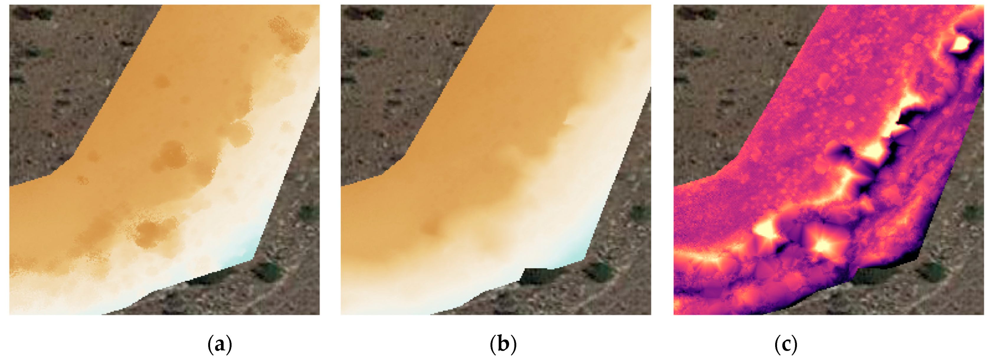
The objectives of remote-sensing surveys include providing topographical information (morphology, altimetry, hydrography); documentation of land use and cover; and detection and description of artificial structures (over or under the surface) and anthropic interventions such as roads, terraces, ditches, and quarries.
Imagery in the visible spectrum is mostly used, but the infrared spectrum also plays an increasingly significant role, as well as multispectral and hyperspectral data [8]. Radar is also used both in properly remote sensing (satellite-- and airplane-based synthetic aperture radar (SAR)) and in proximal sensing (ground penetrating radar (GPR)), recently also mounted on low-flying UAVs [9,10,11,12].
Accurate topographic and morphological information can be obtained by using light detection and ranging (LiDAR) sensors, also known as laser scanners. While the use of ground-based 3D LiDARs is well established for detailed 3D documentation, especially of architecture, airborne LiDAR offers additional advantages, especially to avoid occlusions due to obstacles and to unreachability of tall structures and to obtain valuable data under vegetation cover. This latter feature has proven particularly important in preliminary large-area archeological surveys [13] and is also quite helpful in medium- and small-scale surveys [10,14], both to document exposed structures in densely vegetated contexts and identify artifacts under vegetation cover. Moyes and Montgomery [15] used aerial LiDAR data specifically to find accesses to caves, also under vegetation cover, and based on their results, they could prove that such a methodology is especially useful to obtain quite reliable indicators of possible points of interest with very favorable costs in terms of time and resources. In fact, such a technique amounts to virtually exploring the surface quite rapidly, even when the area is difficult to reach; walking through it exhaustively would require much time, and interesting features that are recognizable from above might not be evident at ground level. Such a preliminary survey cannot replace direct observation altogether but is instrumental in orienting and prioritizing ground survey to potentially interesting sites.
Data fusion can significantly enhance the interpretative performance of heterogeneous datasets and lead to the realization of multiple-layer thematic maps that convey more information than the collection of separate data products. Accurate georeferencing is very important to allow such fusion. Building information modeling (BIM) is also increasingly used in archaeology [16] and may profit significantly from accurate morphological descriptions (as obtained from LiDAR) as a basis for data referencing.
In this paper, we present the results of a case study for use of LiDAR data in the preliminary survey of an archeological site involving artificial cavities hidden by vegetation.
2. Materials and Methods
To evaluate the potential of the UAV-borne LiDAR sensor to discover and document the morphology of artifacts under vegetation cover, we performed a survey of a site that has already been the object of excavations and ground-based survey for several years but is still not completely documented. The advantage of operating in such a site for a pilot project is that some objects of interest (in this specific case, accesses to hypogea) are still hidden from sight and untouched by any archaeological intervention, but the site is accessible, and it is possible to check and validate on the ground the results of the survey.
The specific site considered in this work (S’Elighe Entosu) is located in northern Sardinia, Italy, and specifically in the area of Usini (SS), N 40.648° E 8.541°. It contains a Neolithic necropolis (4000–3500 BC), including three small groups of rock-cut tombs, reused in different periods of Prehistory and Protohistory, in the Roman age and in contemporary times. Archaeological investigations have revealed the existence of a Roman Republican and Imperial necropolis and a post-Roman quarry 80 m west of tombs III and IV [17,18].
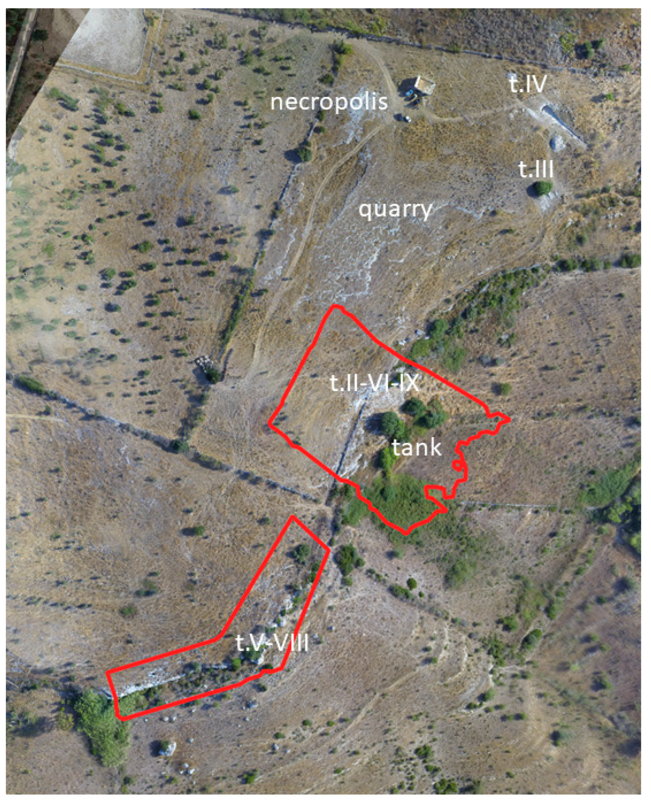
A specific area was surveyed on the edge of a rocky plateau that forms a step overlooking a shallow valley (Figure 1). Along the limestone wall, altered in time by erosion and collapses, Neolithic tombs are present, as well as cavities used in more recent times, including a recent water tank. The rock surface is partly exposed and partly covered by vegetation—mostly low, dense bush and small trees. Such characteristics of the site emphasize the difficulty of accessing and surveying on the ground and make the application of remote sensing quite challenging because the type of vegetation present, especially the small thick bushes extending down to ground level typical of coastal Mediterranean wilderness, is not penetrated by LiDAR or other remote sensing instruments. On the other hand, the area of interest is quite small, so it is possible to examine the data manually and exhaustively at a high level of detail.
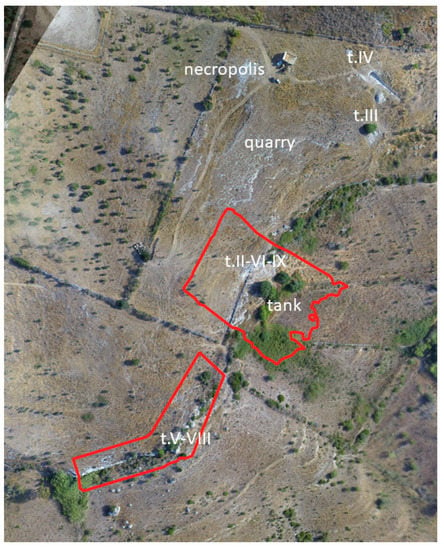
Figure 1.
Orthophotograph of the site surveyed. The location of Neolithic tombs is indicated by t, followed by a Roman numeral. The sites of a Roman necropolis, a post-Roman quarry, and a modern water tank are also indicated. Areas surveyed by the light detection and ranging (LiDAR) sensor are indicated by the red contours.
The objects of interest, just like the case study of [15], are hypogeal spaces (caves or small rooms, partially or entirely dug artificially), and their presence is revealed from the outside by their entrances, which are either horizontal holes opening on (quasi-)vertical cliffs or corridors (dromos) that appear as straight ditches with vertical walls when they have lost (or at least in part never had) their cover. Therefore, the kinds of features that are useful indicators are vertical walls (most often natural and/or quite indistinguishable from natural ones), and holes that look artificial due to their shape and characteristics (taking into account that centuries of weathering and erosion have normally strongly modified them).
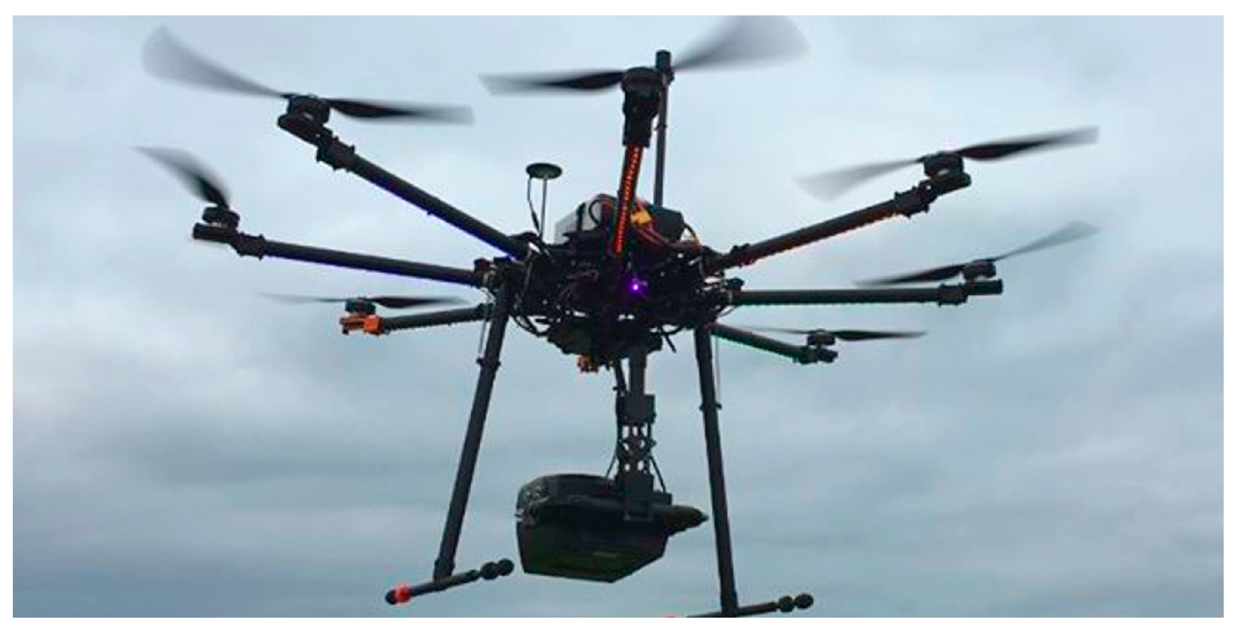
An aerial LiDAR survey was performed using a Yellowscan Mapper (Yellowscan, Saint-Clément-de-Rivière, France, www.yellowscan.fr) mounted on a 1.8 m-diameter octocopter by Foxtech (Tianjin, China, www.foxtechfpv.com), (Figure 2). The sensor is integrated with an accurate inertial unit and a global navigation satellite system (GNSS) unit, which receives both GPS and GLONASS signals, with enhanced positioning based on real-time kinematic (RTK) or post-processed kinematic (PPK). The accuracy of point positioning is better than 10 cm, with a dispersion (precision) of about 40 cm in normal working conditions. The flight profile chosen allowed the acquisition of an average of 63 points/m2, corresponding to a mean spacing of 13 cm. The LiDAR sensor detects up to three echoes per pulse, making it possible to receive last echoes from the ground even in presence of vegetation. This feature allows obtaining a reasonably dense coverage of the surface even when it is not visible from images and cannot be modeled by photogrammetry.
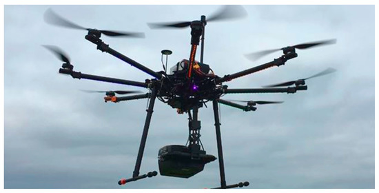
Figure 2.
The Yellowscan Mapper LiDAR flying under the octocopter.
Yellowscan provides a plugin for QGIS (open-source Geographical Information System software, www.qgis.org) to pre-process raw data recorded by the sensor and obtain a point cloud, i.e., a dense set of accurately geo-referenced points composing a 3D model of the surfaces surveyed. Point clouds can be observed and analyzed using appropriate software, in particular Cloud Compare, also an open-source solution (https://www.cloudcompare.org/), freeware as FugroViewer (https://www.fugro.com/about-fugro/our-expertise/technology/fugroviewer, Fugro, The Netherlands), and commercial analysis tools such as LAStools (Rapidlasso GmbH, Gilching, Germany, rapidlasso.com) and Terrasolid (Espoo, Finland, terrasolid.fi).
Flight concentrated on areas not yet thoroughly explored, which are potentially home to hypogea entrances, and areas characterized by difficult accessibility. Two areas in particular were extracted from the raw LiDAR data for detailed and exhaustive analysis (Figure 1).
3. Results
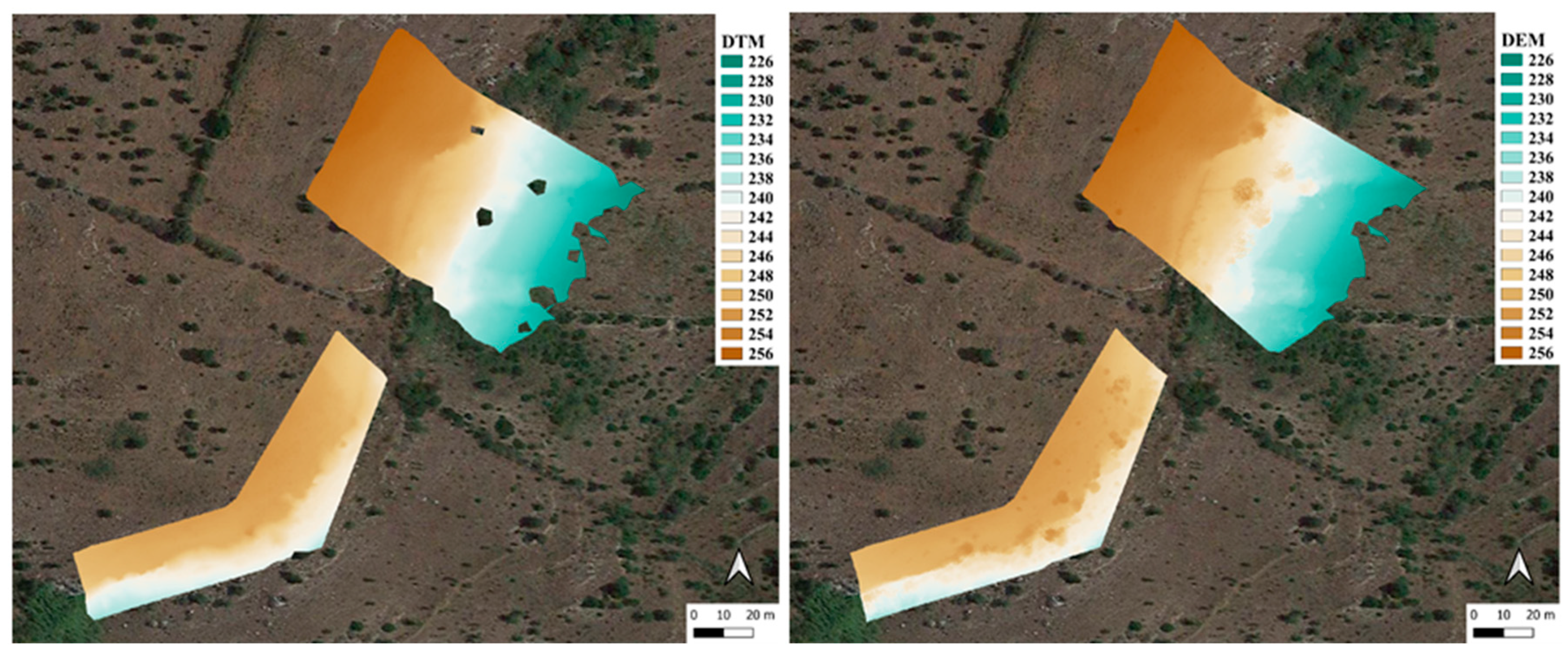
The point cloud (available in a public-domain database [19]) was analyzed by careful inspection in the search for cavities, such as accesses to hypogea or caves or possibly built-up artifacts. To concentrate on the relevant lowest surface, we performed, as is customary, a classification of the LiDAR return points into ground and non-ground points using standard automatic techniques such as implementing in LAStools or Terrasolid software packages. From the ground points, it is possible to obtain a map of the surface elevation organized on a regular grid (raster). This is a digital terrain model (DTM). The dense DTMs obtained with a 0.2-m grid cell size are reported in Figure 3a. Comparing the DTM with a digital elevation model (DEM, Figure 3b), obtained using all points of the cloud, it is apparent that most of the vegetation was correctly recognized and filtered out when extracting ground points.
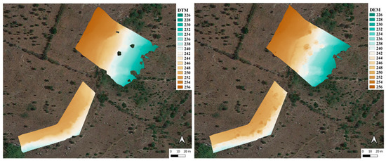
Figure 3.
(a) Digital terrain model (DTM) and (b) digital elevation model (DEM).
Moyes and Montgomery [15] proposed the use of an automatically extracted indicator (local relief modeling (LRM)) to highlight possible regions of interest. Such an indicator is basically obtained by subtracting a smoothed version of the DTM from the original DTM to highlight the sharper discontinuities that are typical features describing artificial structures. This methodology does not amount to automatic recognition of the objects of interest but is useful to drive the attention of the experienced data analysis operator, who must in any case observe the data in a manual fashion.
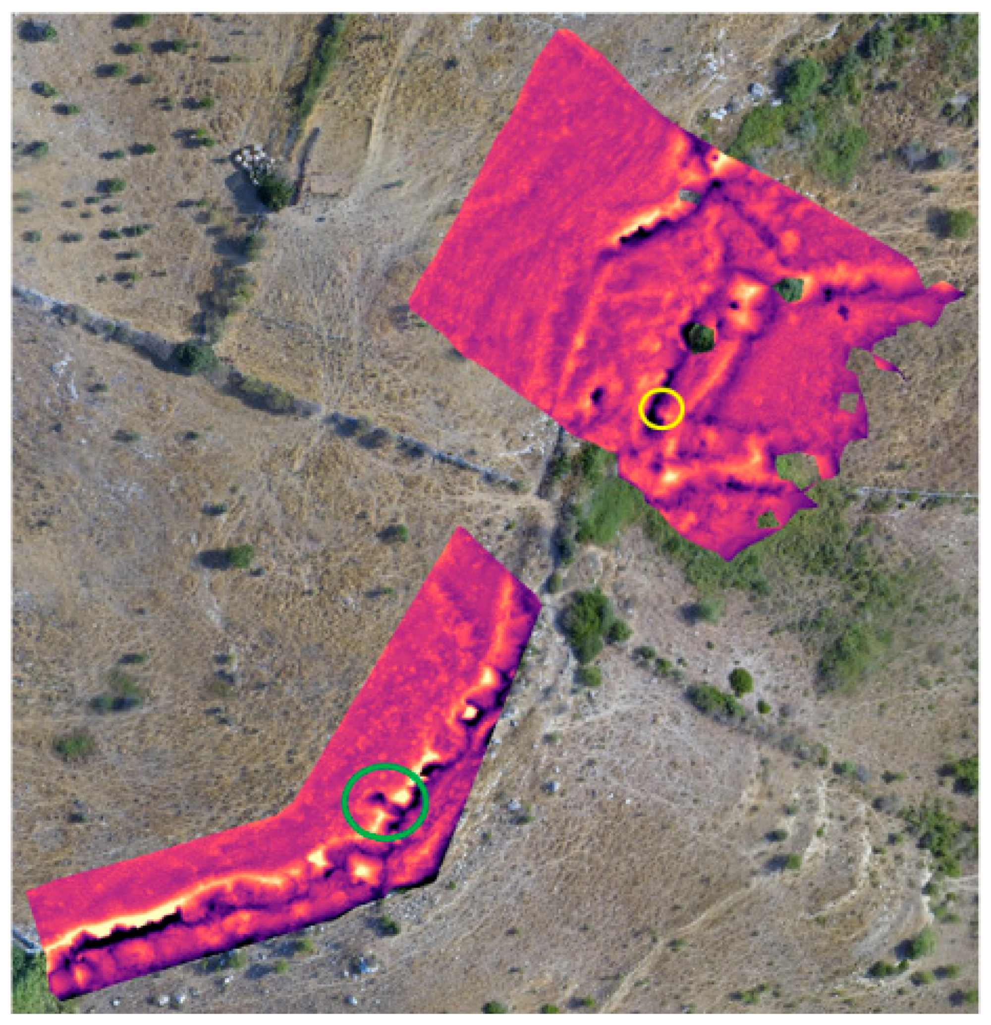
We extracted several indicators from our DTM, including the topographic position index [20] and the terrain ruggedness index [21], along with the LRM. None of these indicators proved very effective in our case study and at the level of detail of our data because the features we were interested in were too similar to each other and to more evident, natural features (in particular the natural cliff), so a large number of false alarms was unavoidable. Nevertheless, the LRM did indeed highlight one of the points of interest that we documented below, as shown in Figure 4.
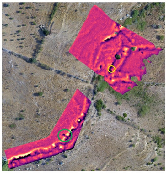
Figure 4.
An essential step of local relief modeling (LRM) consists of taking the difference between the original DTM and a smoothed version of the DTM to highlight sharp transitions. Such an operation is documented here, where false colors go from black/blue for negative differences (original DTM lower than the smoothed version) to yellow/red for positive differences. While most significant anomalies appear on the natural cliff, one specific spot (site#1, green circle) does indeed highlight a point of interest. The other point of interest located by analysis of the point cloud (site#2, yellow circle) does not stand out evidently due to being confused with the cliff area (edge of the rocky plateau).
By looking into a detail of the relevant spot highlighted by the LRM, we can see that, under a small tree, we obtained LiDAR returns from a depression in the ground, as apparent from the DTM in Figure 5.
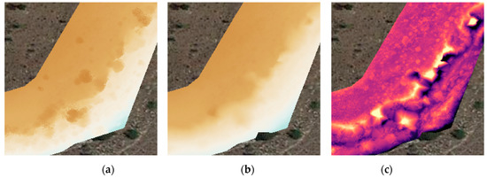
Figure 5.
Details of (a) the DEM, (b) the DTM, and (c) the difference between the original and smoothed DTM, which shows that the point cloud contains a relatively narrow depression under a small tree.
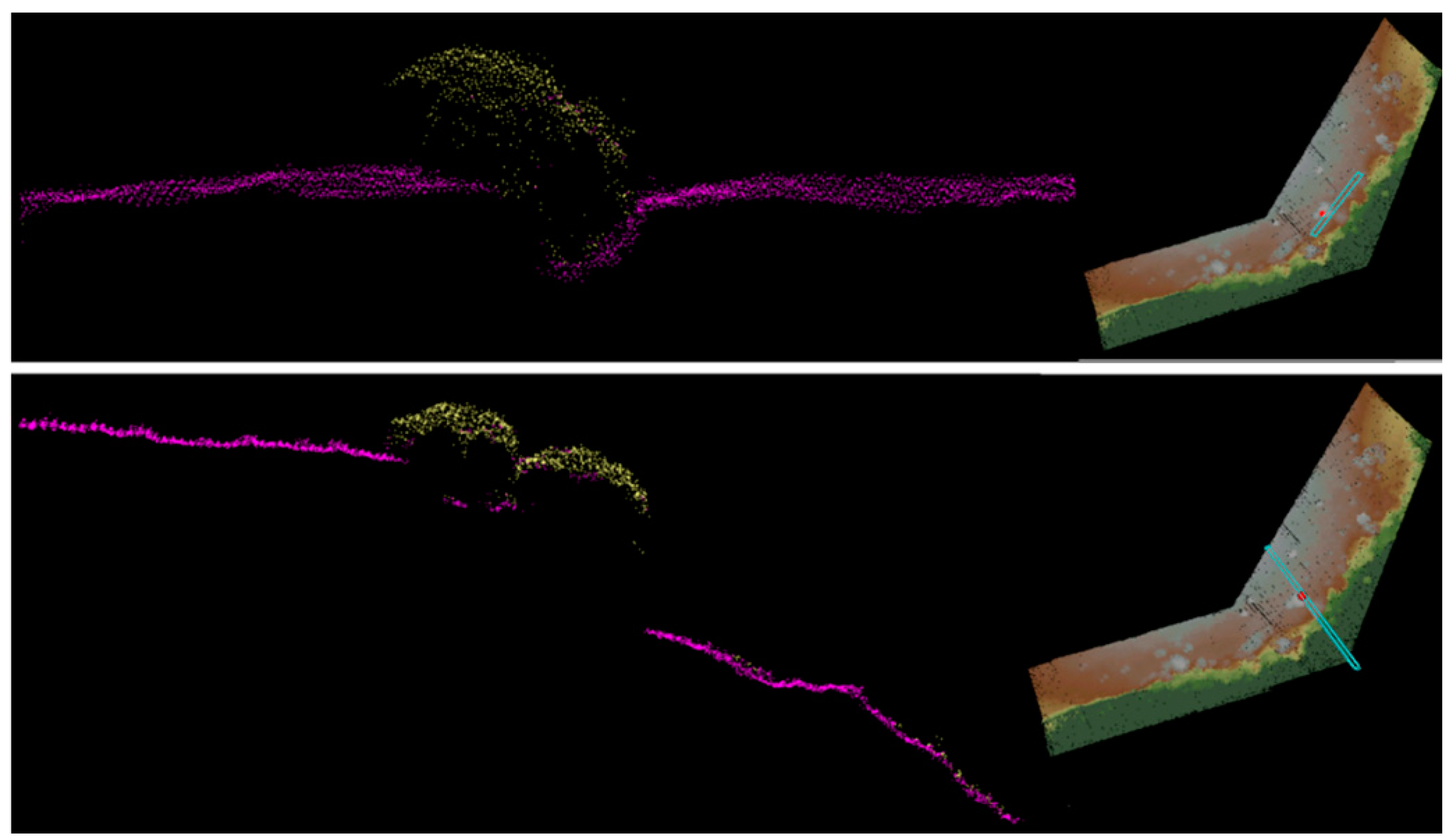
Because even man-made artifacts such as these are rather irregular, especially after centuries of erosion, the technique we used to examine the data was based on taking sliding vertical sections of the point cloud, approximately along or across the slope, and looking for visible anomalies.
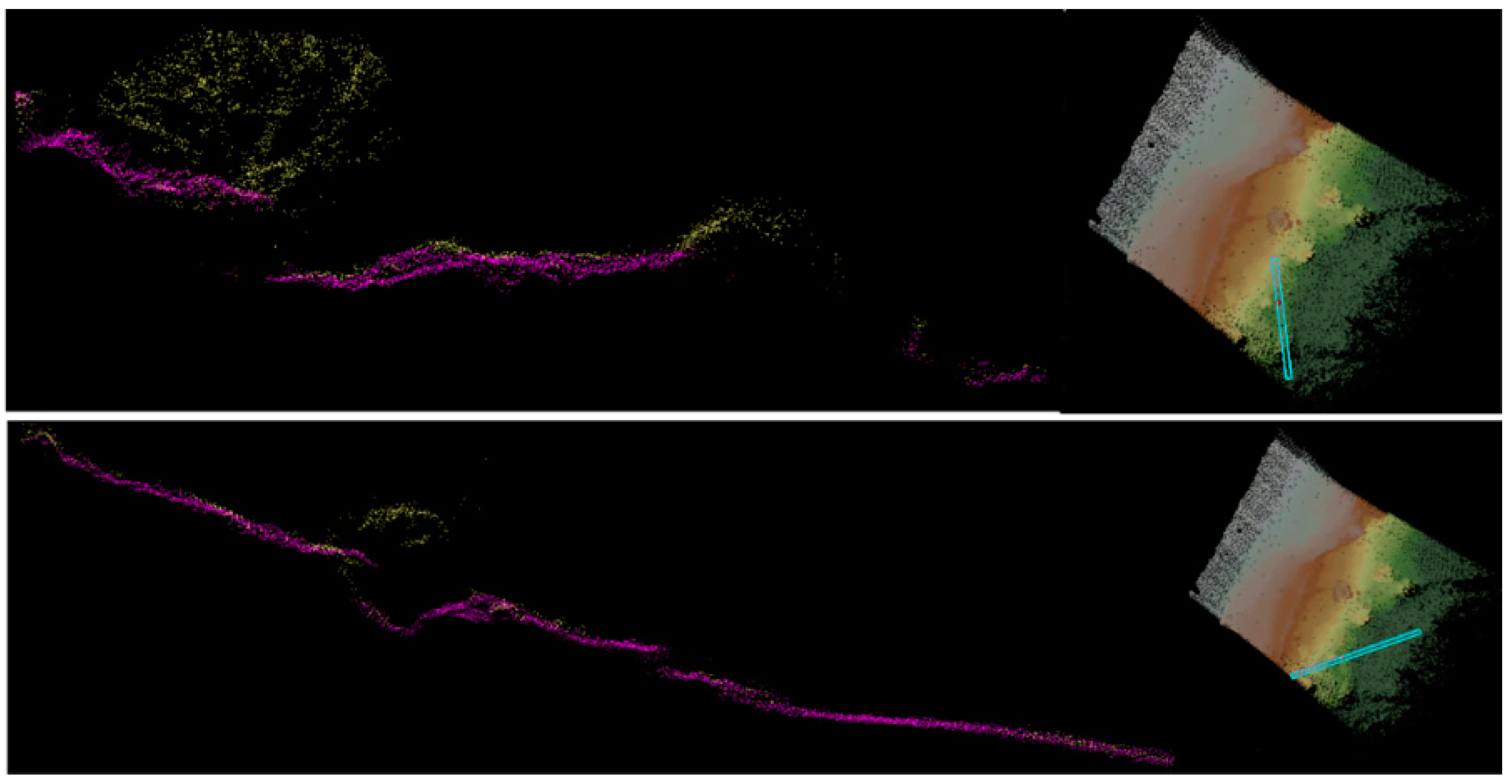
Two relevant spots are documented in Figure 6 and Figure 7, as visualized in FugroViewer. Section positions and extensions are represented in a view of the cloud from above and magnified in a view where points are colored according to classification as ground (purple) and non-ground (yellow) points obtained using LAStools. In both cases, a steep discontinuity (denoting a vertical wall that makes no echo when viewed from above) and a cavity under the bushes are evident.
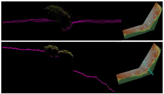
Figure 6.
Sections of the classified point cloud corresponding to relevant site #1. Above: section approximately in the direction of the edge of the plateau; below: section approximately across the edge. The cyan boxes in the top views displayed on the right of the panels indicate the position and extension of the sections. Red points indicate the approximate location of the point of interest (coordinates were taken manually for the purpose of locating the points on the ground).
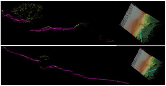
Figure 7.
Sections of the classified point cloud corresponding to relevant site #2. Sections were taken along two orthogonal directions not directly oriented with the edge of the plateau (above: section taken approximately in the North-South direction; below: section East-West).
The insets on the right of the images show the position and extension of the sections. These sections were taken small enough to enhance visualization; however, the manual search was performed by carefully observing sections taken across the entire extension of the cloud in several directions, making use of the convenient feature of FugroViewer that allows sliding the section position very easily with the mouse wheel.
It is to be noted that some points are wrongly classified as ground or non-ground. Nevertheless, the color is just intended as a help for the data analyst, who was in any case required to make an exhaustive search for shapes and features that cannot be standardized enough to allow for automatic recognition.
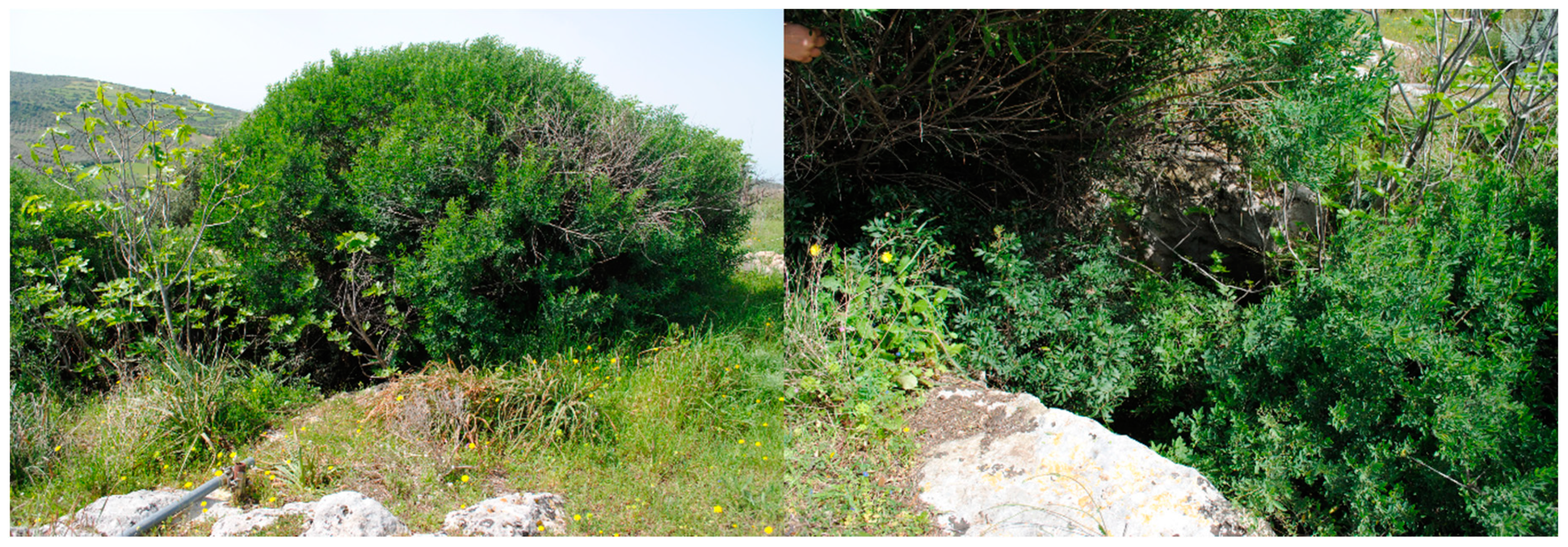
Positions of the cavities were recorded and used for a ground survey. Site #1 is indeed the known entrance of tomb VIII and is located in the point of interest highlighted in Figure 4 and Figure 5. Figure 8 shows two views of the site at ground level. It is apparent that the cavity is almost invisible, even at a closer look, being mostly covered by a large, dense bush and smaller vegetation growing also from the inside.
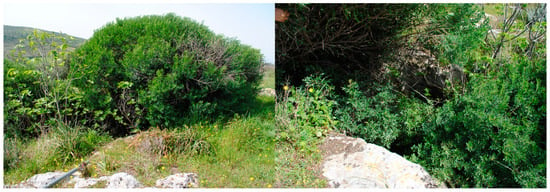
Figure 8.
Two views of site #1.
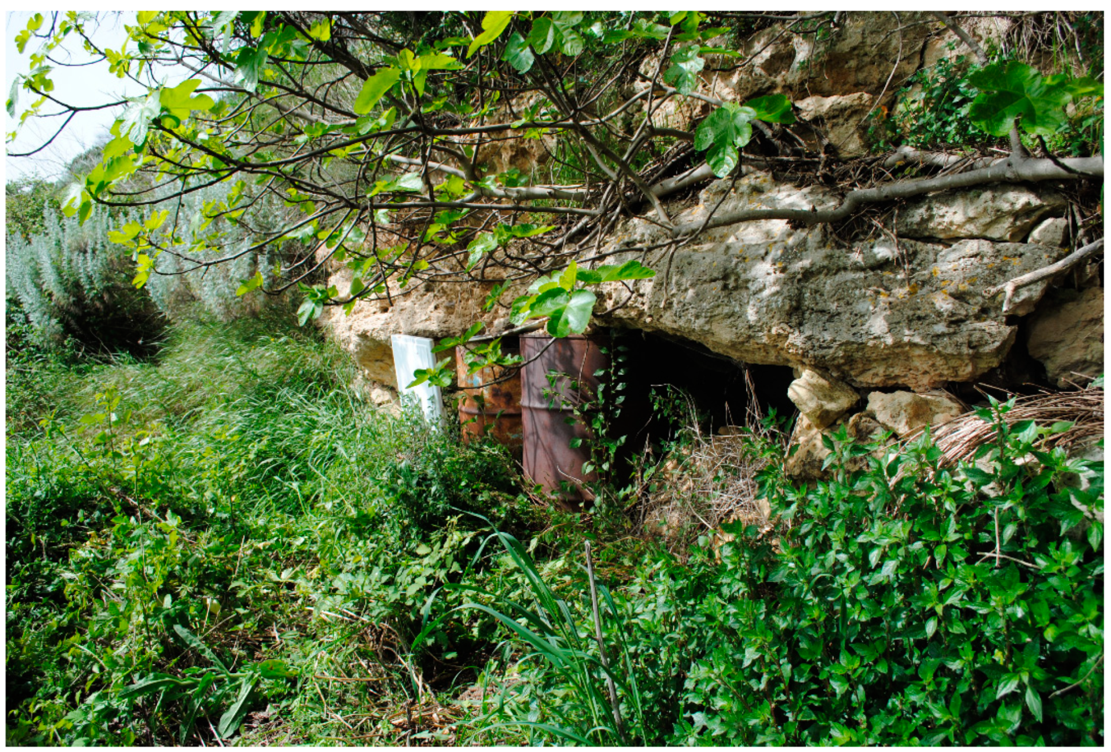
Site #2 is a relatively recent water tank close to a small cave, partially closed by a dry-stone wall, two barrels, and a panel. Even if this is not of archaeological interest, it is indeed an artificial structure, therefore a legitimate candidate for the survey. Also, these cavities, in particular the tank in the lower left of Figure 9, are almost completely hidden by the vegetation.
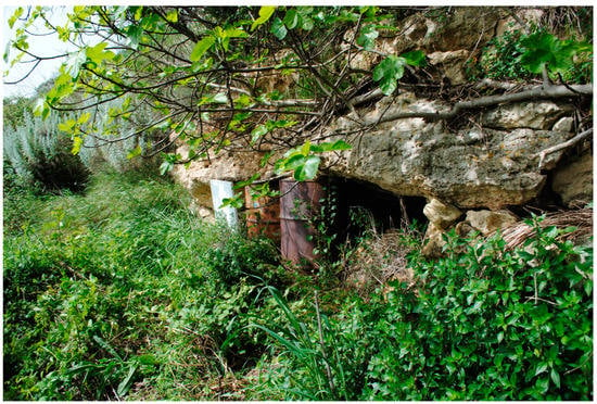
Figure 9.
View of site #2.
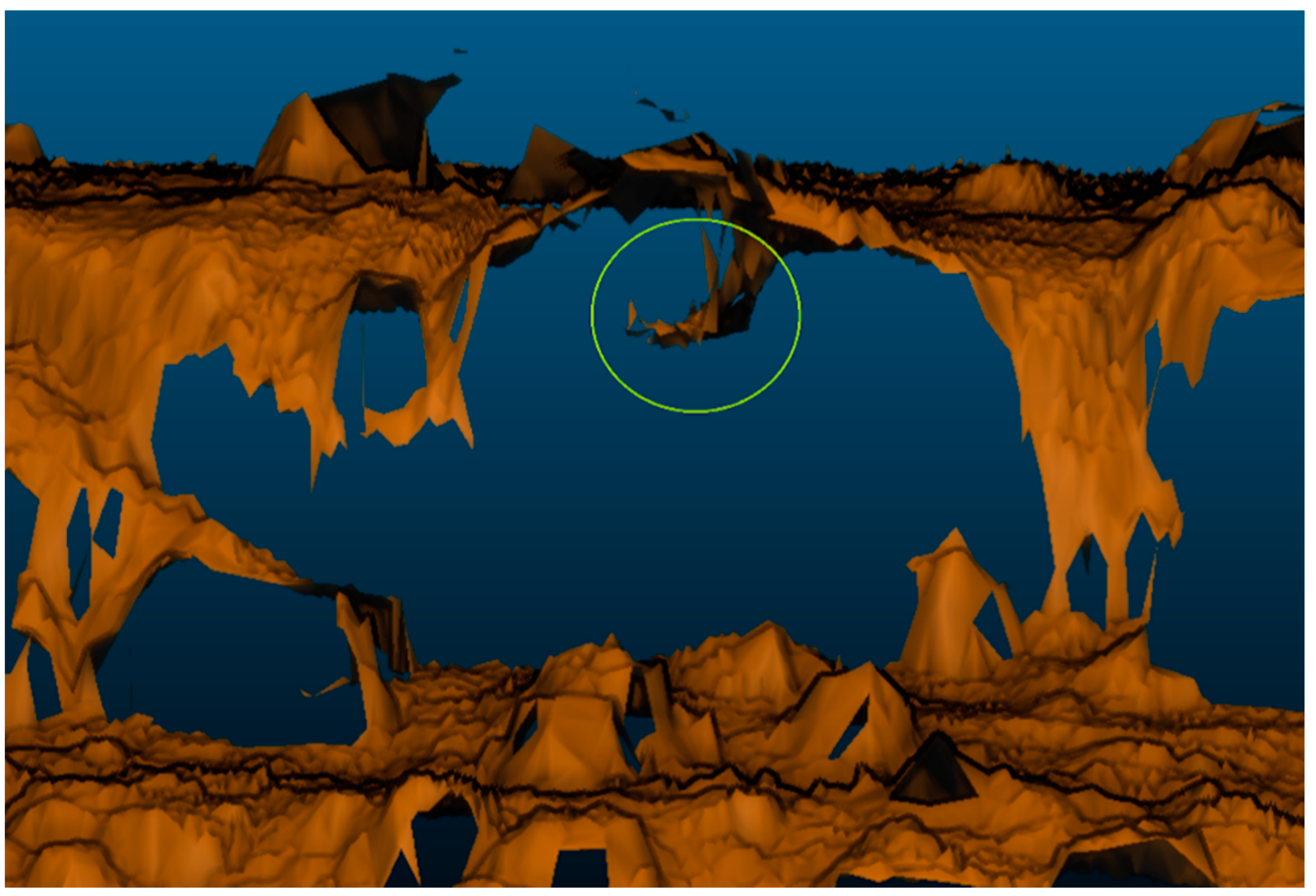
A different way of examining the data is by creating a mesh structure from the points of the cloud labeled as ground. In this way, it is possible to examine the surface, also under vegetated cover, to look for relevant shapes. Of course, the surface is incomplete, and the classification of ground points carries errors, especially where dense bush extends down to the ground, fooling the algorithm into considering ground the only surface that is actually present in the point cloud. Nevertheless, this view can, in some cases, make relevant surface anomalies even more evident than sections. This is the case, e.g., for site #1, as apparent in Figure 10.
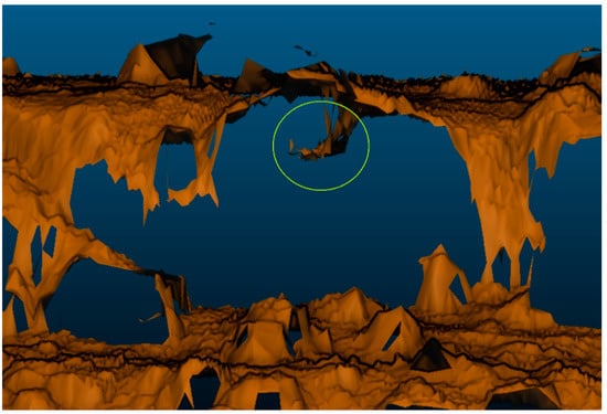
Figure 10.
A mesh view relative to site #1. The view was taken in a horizontal direction from a position in front of the plateau edge. The vertical wall of the plateau is not present in the mesh because no returns were received by the LiDAR looking from above. This condition makes it even easier to “see through the wall” to the cavity (tomb entrance) behind. Such cavity takes the form of a step down to the hypogeum entrance and is highlighted by a green ellipse. It is also visible from the other side, but in this case, it is more clearly seen from such angle (horizontally, looking into the stone cliff) thanks to the gap in the mesh.
4. Discussion
The case study presented was intended to experiment with an aerial LiDAR survey for preliminary archaeological documentation in a relatively difficult context where small and geometrically irregular artifacts are covered by dense bush extending down to the ground.
Analysis of the point clouds obtained was performed manually by carefully observing sections of the data. Even if it was not possible to employ an automatic detection algorithm in this case, examining the data was significantly easier and faster than personally exploring the grounds. Of course, validation must be done by direct inspection, but the case study proved that such inspection can be guided very efficiently based on the remotely sensed data. In this context, features of interest are very subtle, easily confused with natural features, and difficult to characterize univocally. For this reason, we resorted to expert observations of topographic details, so generalization of the detection stage appears elusive in this case study. Future developments of this work will address the issue of enhancing the methodology to make it more automatic and more straightforwardly applicable to different contexts. This may involve both choosing objective feature characteristics that are associated with artificial structures and employing learning machines. Where the objective of the survey is finding more clearly shaped features such as roads and paths, traces of walls, larger depressions, etc., analysis of the mesh of ground points, in this case done manually and even guided by a known anomaly position, could be performed partially or completely automatically, e.g., by examining gradient maps obtained from the mesh (or from a DTM derived from it). On the other hand, employing learning methods such as deep learning requires a large database of relevant cases that was not available at this stage.
The ground surface extracted from the LiDAR data constitutes the best topographic baseline to support geolocalization and representation of data obtained by other remote-sensing sensors or by ground or proximal measurements and surveys that also aim to realize a BIM documentation of the site. The aerial LiDAR DTM is very accurate (order of 0.1 m positioning error) and describes the actual ground more precisely than a photogrammetric 3D model, while the latter can be very usefully integrated to provide higher resolution visual rendering.
5. Conclusions
A case study for a preliminary survey of a partially known (but treated as unknown) archaeological site by drone-carried LiDAR sensor was presented. The survey, which covered several hectares in a less than half-an-hour flight followed by few hours of data preprocessing and analysis proved that LiDAR can provide in a short time, and quite easily, very useful information to detect hidden artificial structures and provide a baseline for site documentation. Integration of LiDAR data with both remotely and closely sensed heterogeneous data enhances the usefulness of the individual datasets by data fusion.
Author Contributions
Conceptualization, M.G.M. and M.M.; methodology, M.B., S.E., P.F., M.G.M., M.M.; validation, M.G.M. and P.F.; formal analysis, P.F. and S.E.; investigation, M.B.; resources, S.E. and P.F.; data curation, P.F.; writing—original draft preparation, M.B.; writing—review and editing, M.B., S.E., P.F., M.G.M., M.M.;visualization, S.E.; supervision, M.G.M.; project administration, M.G.M. and M.B.; funding acquisition, M.G.M. and M.M.; All authors have read and agreed to the published version of the manuscript.
Funding
This research was partially funded by Regione Autonoma Sardegna through the project “UAV and LiDAR Technology for Remote Sensing in Archaeology” (ULTRA).
Institutional Review Board Statement
Ethical review and approval were waived for this study, due to: “Not applicable” for studies not involving humans or animals.
Informed Consent Statement
“Not applicable” for studies not involving humans.
Data Availability Statement
The LiDAR point clouds used for this work are publicly available on the Mendeley repository [19].
Conflicts of Interest
The authors declare no conflict of interest. The funders had no role in the design of the study; in the collection, analyses, or interpretation of data; in the writing of the manuscript, or in the decision to publish the results.
References
- Corsi, C.; Slapšak, B.; Vermeulen, F. (Eds.) Good Practice in Archaeological Diagnostics: Non-Invasive Survey of Complex Archaeological Sites; Springer: Cham, Switzerland; Heidelberg, Germany; New York, NY, USA; Dordrecht, The Netherlands; London, UK, 2013. [Google Scholar]
- Campana, S.; Piro, S. Seeing the Unseen; Taylor & Francis: London, UK, 2009. [Google Scholar]
- Bozoki-Ernyey, K. European Preventive Archaeology; National Office of Cultural Heritage: Budapest, Hungary, 2007. [Google Scholar]
- Güll, P. Archeologia Preventiva; Dario Flaccovio Editore: Palermo, Italy, 2015. [Google Scholar]
- Citter, C.; Arnolud-Huyzendeveld, A. New approaches to old issues: The application of predictive maps in archaeology, a case study: Modelling the location the Grosseto salt work from 700BC to AD 1200. Mediev. Settl. Res. 2012, 27, 1–11. [Google Scholar]
- Burgers, G.L.M.; Kluiving, S.J.; Hermans, R.A.E. (Eds.) Multi-inter- and transdisciplinary research in landscape archaeology. In Proceedings of the 3rd International Landscape Archaeology Conference in Rome, Rome, Italy, 17–20 September 2014; University Library, Vrije Universiteit: Amsterdam, The Netherlands, 2016. [Google Scholar]
- Cambi, F. Archeologia dei Paesaggi Antichi: Fonti e Diagnostica; Carocci: Roma, Italy, 2003. [Google Scholar]
- Cavalli, R.M. Integrated approach for archaeological prospection exploiting airborne hyperspectral remote sensing. In Good Practice in Archaeological Diagnostics; Springer: Cham, Switzerland, 2013; pp. 87–112. [Google Scholar]
- Benner, S.M.; Brodkey, R.S. Underground heat detection using differential heat analysis. Archaeometry 1984, 26, 21–36. [Google Scholar] [CrossRef]
- Rowlands, A.; Sarris, A. Detection of exposed and subsurface archaeological remains using multi-sensor remote sensing. J. Archaeol. Sci. 2007, 34, 795–803. [Google Scholar] [CrossRef]
- Piga, C.; Piroddi, L.; Pompianu, E.; Ranieri, G.; Stocco, S.; Trogu, A. Integrated geophysical and aerial sensing methods for archaeology: A case history in the punic site of Villamar (Sardinia, Italy). Remote Sens. 2014, 6, 10986–11012. [Google Scholar]
- Casana, J.; Kantner, J.; Wiewel, A.; Cothren, J. Archaeological aerial thermography: A case study at the Chaco-era Blue J community, New Mexico. J. Archaeol. Sci. 2014, 45, 207–219. [Google Scholar] [CrossRef]
- Chase, A.F.; Chase, D.Z.; Weishampel, J.F.; Drake, J.B.; Shrestha, R.L.; Slatton, K.C.; Awe, J.J.; Carter, W.E. Airborne LiDAR, archaeology, and the ancient Maya landscape at Caracol, Belize. J. Archaeol. Sci. 2011, 38, 387–398. [Google Scholar] [CrossRef]
- Poscetti, V.; Malatesta, S.G.; Cirilli, V.; Lella, F.; Rondinelli, V.; Esposito, S.; Balsi, M. Preliminary results of the Castelmonardo project. Archeologia Calcolatori 2017, 28, 391–402. [Google Scholar]
- Moyes, H.; Montgomery, S. Locating cave entrances using lidar-derived local relief modeling. Geosciences 2019, 9, 98. [Google Scholar] [CrossRef]
- López, F.J.; Lerones, P.M.; Llamas, J.; Gómez-García-Bermejo, J.; Zalama, E. A review of heritage building information modeling (H-BIM). Multimodal Technol. Interact. 2018, 2, 21. [Google Scholar] [CrossRef]
- Melis, M.G. (Ed.) Usini. Ricostruire il Passato. Una Ricerca Internazionale a S’Elighe Entosu; Carlo Delfino Editore: Sassari, Italy, 2010. [Google Scholar]
- Melis, M.G. (Ed.) Usini. Nuove ricerche a S’Elighe Entosu. In Quaderni del LaPArS 2; Università di Sassari—LaPArS: Sassari, Italy, 2016. [Google Scholar] [CrossRef]
- Data for Paper: “Preliminary Archeological Site Survey by UAV-Borne LiDAR”, Mendeley Data, V1. Available online: https://data.mendeley.com/datasets/wbkky67dvc/2 (accessed on 18 January 2021).
- De Reu, J.; Bourgeois, J.; Bats, M.; Zwertvaegher, A.; Gelorini, V.; De Smedt, P.; Chu, W.; Antrop, M.; De Maeyer, P.; Finke, P.; et al. Application of the topographic position index to heterogeneous landscapes. Geomorphology 2013, 186, 39–49. [Google Scholar] [CrossRef]
- Riley, S.J.; DeGloria, S.D.; Elliot, R. A terrain ruggedness index that quantifies topographic heterogeneity. Intermt. J. Sci. 1999, 5, 23–27. [Google Scholar]
Publisher’s Note: MDPI stays neutral with regard to jurisdictional claims in published maps and institutional affiliations. |
© 2021 by the authors. Licensee MDPI, Basel, Switzerland. This article is an open access article distributed under the terms and conditions of the Creative Commons Attribution (CC BY) license (http://creativecommons.org/licenses/by/4.0/).

