Technical Note

Flight Experiment Validation of Altitude Measurement Performance of MOSIR on Tianwen-1 Orbiter

1
Key Laboratory of Lunar and Deep Space Exploration, National Astronomical Observatories, Chinese Academy of Sciences, Beijing 100101, China
2
School of Astronomy and Space Science, University of Chinese Academy of Sciences, Beijing 100049, China
3
No. 38 Research Institute of China Electronics Technology Group Corporation, Hefei 230088, China
4
Institute of Advance Study, Shenzhen University, Shenzhen 518960, China
*
Author to whom correspondence should be addressed.
Remote Sens. 2021, 13(24), 5049; https://doi.org/10.3390/rs13245049
Submission received: 14 November 2021 / Revised: 7 December 2021 / Accepted: 8 December 2021 / Published: 13 December 2021
(This article belongs to the Section Satellite Missions for Earth and Planetary Exploration)

Abstract

:
The MOSIR (Mars Orbiter Subsurface Investigation Radar) is one of the scientific payloads carried by the Tianwen-1 orbiter. MOSIR conducted a ground experiment in the desert near Dengkou County, northern China, before the launch of the Tianwen-1 satellite. The MOSIR prototype was suspended from a hot air balloon and flew over a flat region at an altitude of 2500–3300 m. This experiment aimed to verify the system performance and data processing. The data collected in subsurface sounding mode is performed range compression, and the altitude measurement data removes invalid data. After processing, the altitude measurement results of two operating modes are analyzed and compared with that of the Global Position System (GPS), which verifies the accuracy of the altitude measurement.

Graphical Abstract

1. Introduction

The Ground Penetrating Radar (GPR) is an important method used widely in planetary exploration. It plays a crucial role in searching for water ice and studying the geologic evolution process in terrestrial planets. The first orbiter-based GPR in planetary exploration is ALSE onboard Apollo 17 [1], and the GPR deployed on the Mars orbiters highlighted its advantages, which leads the research group to attach more importance to the effect of GPR in the following missions.
On 23 July 2020, the Tianwen-1 Mars probe was successfully launched by the Long March-5 carrier rocket in the Wenchang Space Launch Center [2] and reached the orbit of Mars on 10 February 2021. Tianwen-1, China’s first Mars exploration mission, consists of three components: an orbiter, a lander, and a rover. The orbiter operates in a highly elliptical polar orbit with a perimartian altitude of 260 km and an eccentricity of 0.589, and its inclination angle is 78.2 deg. It carried seven scientific payloads, including MOSIR (Mars Orbiter Subsurface Investigation Radar) [3,4]. The scientific objectives of MOSIR are:
  • To make the passive low-frequency observation in the transfer of the spacecraft into the Mars orbit;
  • To obtain the subsurface stratigraphy of Mars, especially the distribution of water and water ice;
  • To probe the Martian large-scale altimetry;
  • To measure the total electron content of the ionosphere.
MOSIR transmits electromagnetic waves to the Martian sub-satellite point and receives echoes from the Martian surface and subsurface at an altitude of 265–800 km [5]. The electromagnetic wave can penetrate medium (such as Martian soil, ice, rock, and other geological materials) and be reflected and scattered by the interface between different media [6]. This feature allows MOSIR to investigate the subsurface layered structure. We can obtain scientific information such as time delay, echo strength, polarization from the echoes. The medium’s dielectric constant, attenuation characteristic, and polarization characteristic can be deduced from this information. Therefore, MOSIR can study the Martian subsurface structure and obtain the physical properties of the subsurface materials.
MOSIR operates in dual-frequency channels—low frequency (10 MHz–15 MHz or 15 MHz–20 MHz) and high frequency (30 MHz–50 MHz)—and transmits linear frequency modulation signal (LFM), widely used in synthetic aperture radar. LFM signal has many advantages: it can transmit more energy without increasing the transmitter power. In terms of the frequency channels, MOSIR has designed four operating modes: Low-Frequency Radio Receiving mode (LFRR), High-Frequency Subsurface Sounding mode (HFSS), Low-Frequency Subsurface Sounding and Active Ionosphere Sounding mode (LFSS+AIS), and Altitude Detection Mode (ADM) [5]. In HFSS mode, the range resolution is ~7.5 m, and in LFSS mode, the range resolution is ~30 m in free space. Due to high operating orbits (between 265 km and 800 km), the along-track and cross-track resolutions are rough without processing. The synthetic aperture process can improve horizontal resolution, designed to operate on the ground [7]. MOSIR will significantly improve the resolution after the ground processing, achieving a horizontal footprint of a hundred-meter level along-track and a thousand-meter level cross-track. The expected penetration depth of MOSIR is ~1 km in the material of water ice and deeper than 100 m in Martian soil.
Before Tianwen-1 launched, two orbiter subsurface penetrating radars, known as MARSIS (European Space Agency, Europe; operating frequency: 1.3 MHz–5.5 MHz) and SHARAD (National Aeronautics and Space Administration, America; operating frequency: 15 MHz–25 MHz), are still operative nowadays [8,9,10,11,12,13] and found water ice and even liquid water buried beneath the subsurface [14,15,16,17,18]. Compared to MARSIS and SHARAD, MOSIR has dual frequency channels with a maximum central frequency difference of 27.5 MHz. The frequency band of MOSIR LFSS mode is between MARSIS and SHARAD; the bandwidth (5 MHz) of MOSIR is wider than 1 MHz of MARSIS and less than 10 MHz of SHARAD. As a result, MOSIR can provide moderate penetration depth and range resolution [19]. In particular, MOSIR possesses dual-polarization detection ability, which can receive cross-polarization echoes (HH and HV). The orbiter-based Martian surface penetrating Radar (MOSIR) will provide new insights to discover water ice distribution on Mars with dual-polarization observations [5].
In the summer of 2019, the MOSIR ground experiment proceeded in the Inner Mongolia Autonomous Region. MARSIS and SHARAD did not conduct the ground experiment in a Mars analogue environment before operation. The large antenna size, the minimum detection range, and other factors must be considered in experimental design with few similar experiment scenarios to reference [20]. A hot air balloon was finally chosen as the carrier to suspend the MOSIR prototype and flew over the experimental area. The radar investigation focused on altitude measurement with different operating modes, which allowed for evaluating subsurface sounding capabilities and the validness of the data processing method developed for the MOSIR data, mainly range compression for the HFSS data. We assessed the accuracy of the altitude measurement results through deviation from the reference values provided by GPS.

2. The Condition of the Flight Experiment

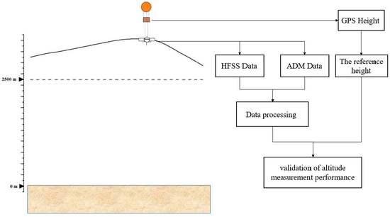
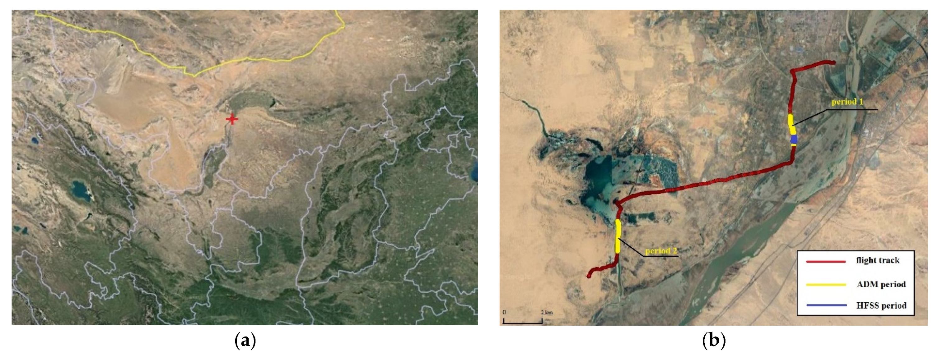
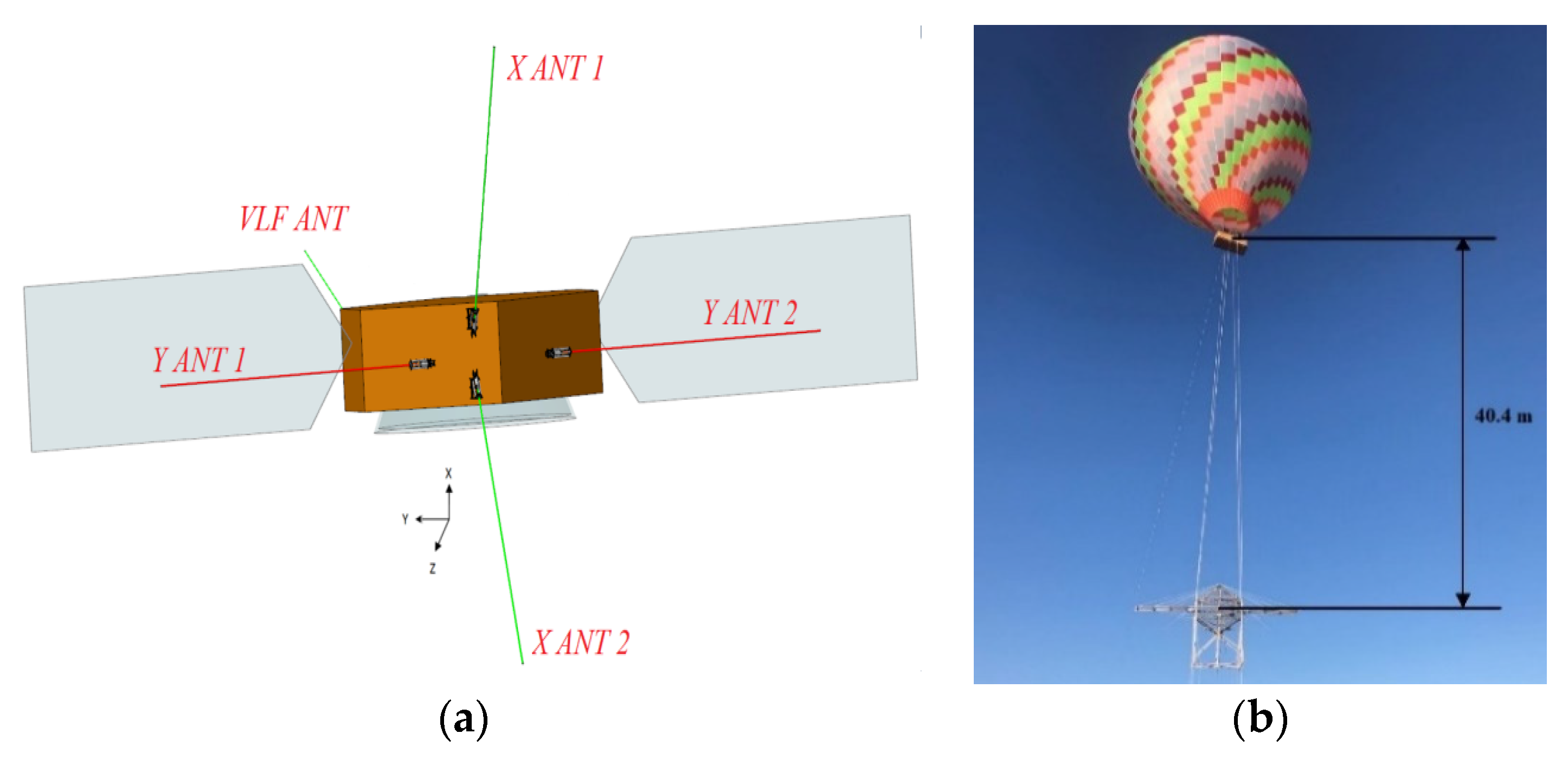
2.1. Experimental Condition
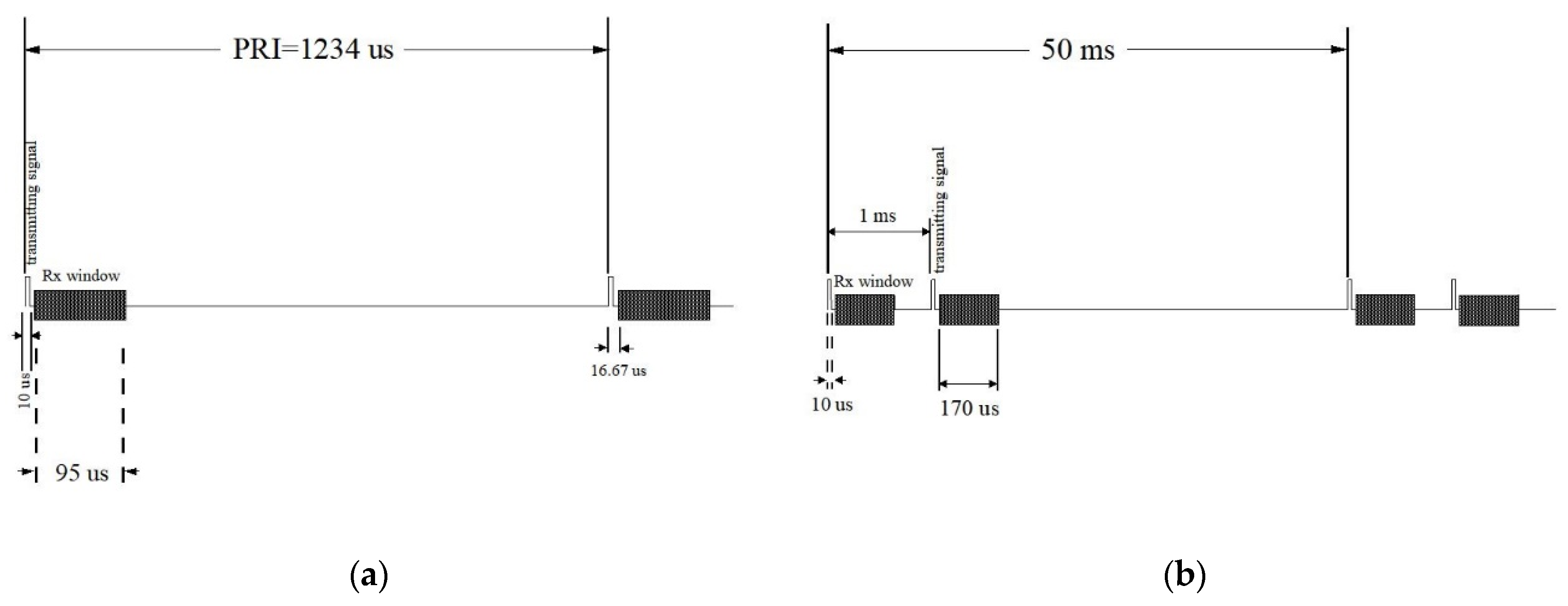
Dengkou County is located in China’s Inner Mongolia Autonomous Region. The experimental area is southeast of Dengkou County, at the edge of the Ulanbuh desert, with a central location of 106.93°E, 40.25°N (Figure 1a). Deserts are suitable for MOSIR ground experiments because electromagnetic waves can easily penetrate dry sand with low attenuation, just as dry, low-density deposits and ice-rich materials on Mars exhibit low dielectric loss properties [21,22]. The flat terrain of the whole experimental area facilitates the operation of hot air balloons and the recovery of the hanging platform. The performance of LFSS was not verified in ground experiments due to the influence of low-frequency interference as the testing area is near the county.
MOSIR will operate at an altitude of 265 km–800 km in Mars orbit, which is difficult to simulate on Earth fully. The MOSIR team selected the AX-11 balloon as the MOSIR radar platform after considering the practical factors such as maximum wind speed, flight altitude, payload, and the influence of aircraft.
Four primary antennas (X ANT1, X ANT2, Y ANT1, Y ANT2, shown in Figure 2a) are mounted on the satellite side, and the +Z axis will always face Mars or the ground. The length of each Y antenna is 5 m, and each X antenna is 4.5 m [5]. MOSIR antennas are mounted on the Tianwen-1 orbiter model to maintain the relative location and angle in the ground experiment. The orbiter model has a wooden bracket for the convenience of taking off and landing (Figure 2b).
The ground experiment of MOSIR began on 22 August 2019, after a series of preparatory work. During flight tests, necessary instruments, including gas cylinders and the GPS mobile stations, are carried in the balloon basket. To avoid the influence of the hot air balloon platform on radar performance, the MOSIR prototype was kept at a vertical distance of ~40 m away from the balloon basket and suspended by the ropes (Figure 2b). The balloon flew about ~22 km at an altitude of ~3 km. Its flight path is affected by wind speed, wind direction, and residual fuel, as shown in Figure 1b. During the flight, GPS mobile stations (Leica GS16) continuously recorded latitude, longitude, and altitude in real-time. MOSIR worked alternately in ADM and HFSS mode, collecting two ADM data blocks and one HFSS data block.

2.2. Radar Settings

MOSIR is an orbiting subsurface radar sounder using synthetic aperture technology. High operating orbit and the ionosphere cause strong attenuation of the signal as it passes through the Martian atmosphere, so the pulse length and the transmitted power are designed to increase the power of the transmitted signal (pulse length > 40 μ s and power = 100 w) [5]. However, the conditions for the ground experiments are very different. The balloon can only reach an altitude of ~3 km, and some radar parameters should be modified to suit the experimental conditions, as shown in Table 1.
MOSIR operating modes are also adjusted based on the experimental conditions. In contrast with the actual performance condition [5], we shortened the pulse length to 10 μs and chose the longest PRI (Pulse Repetition Interval) in the settings. In ADM mode, we canceled the onboard accumulation. Then, all the ADM data was downlinked after processing. Time schemes of ADM and HFSS modes in the ground experiment are shown in Figure 3.

3. Data Processing of the MOSIR Ground Experiment
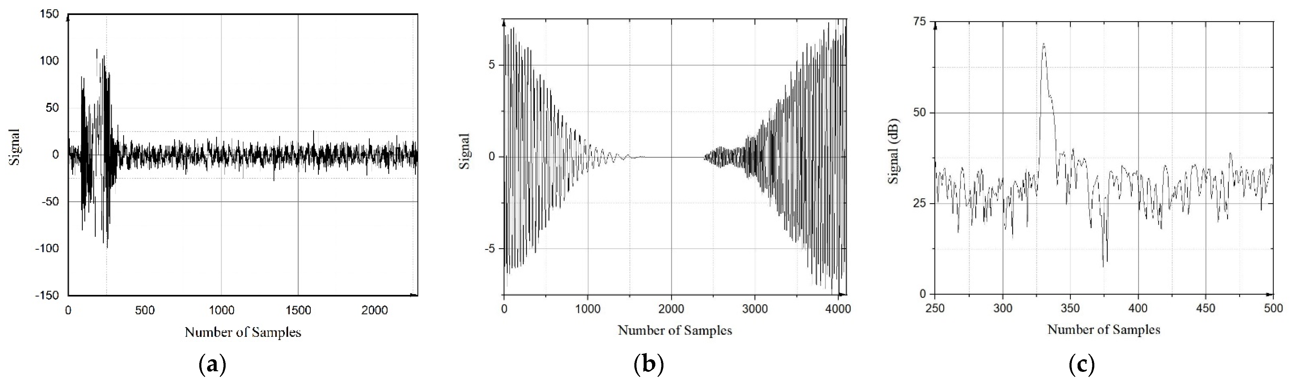
First of all, we choose the height provided by the GPS mobile station as the reference value of the data. It is necessary to correct terrain and time error for the height provided by GPS. Terrain correction includes terrain interpolation and flight altitude correction. The ground elevation interpolation provides the estimated elevation of the sub-satellite point, which is used to minus the corresponding point’s altitude and obtain accurate flight height to accomplish terrain correction. Moreover, the time error results from a lack of automatic timing and causes time deviation of the altitude curve. We align the highest point of GPS and ADM data in time (Radar possesses an automatic timing function) due to the highest point’s uniqueness. After the correction, the height provided by the GPS can represent the distance between the GPS and the sub-satellite surface well, then we subtract the length of ropes between the radar and the basket (40.4 m) to obtain the final reference value.
LFM signal transmitted by MOSIR has a long pulse length, making the echoes hard to identify without data processing. Range compression is the key to solving this problem. HFSS data processing of the MOSIR ground experiment mainly focuses on range compression. The effective sounding track length of several hundred meters is insufficient for azimuth compression.
The principle of range compression is as follows:
  • The receiving echo:
x ( t ) = A e j ( π k ( t 2 r c c ) 2 ) ,   2 r c c τ 2 < t < 2 r c c + τ 2
  • The matched filter:
h ( t ) = e j π k t 2 ,
H ( f ) = e j π f 2 k ,                                                           B 2 < f < B 2
  • The output of the matched filter:
Y ( f ) = X ( f ) H ( f ) ,
  • Time-domain output:
y ( t ) = B s i n c ( π B ( t 2 r c c ) ) ,
A is a constant that represents echo amplitude, B is frequency bandwidth, τ represents pulse length of echo, rc is the distance between the radar and the reflector, c represents light speed and k is the frequency modulation rate equal to B divided by τ. Range compression can also be realized through the convolution of the receiving echo and the matched filter in the time domain.
Range compression can compress a longer LFM signal into a shorter Sinc function, concentrating the echo’s energy on the main lobe. After range compression, the bandwidth of the time-domain output is narrow by τB times. However, the window function, ionosphere distortion, phase error, and other factors can also affect this narrowing rate and expand the main lobe’s width [23,24].
The side lobes from strong surface echoes will be suppressed to detect weak subsurface echoes, and the peak sidelobe ratio (PSLR) limit is above 50 dB. Using an ideal LFM signal as a reference function cannot satisfy this requirement because waveform distortion will occur after the signal passes through the transmitting channel, antennas, and receiving channel [25]. The correction coefficient for the reference function can be inverted from the following measurement results:
  • Ground calibration that obtains characteristics of transmitting and receiving antennas;
  • Internal loop calibration that obtains characteristics of the Tx/Rx channels;
  • The far-field test that measures the whole system response.
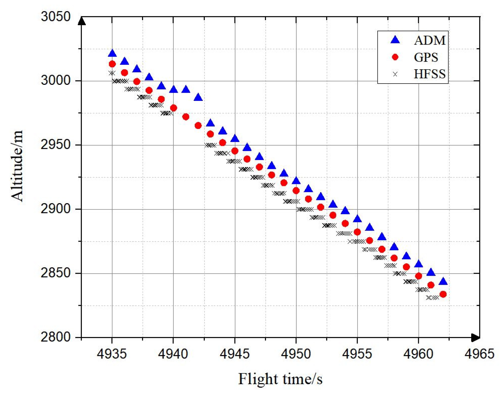
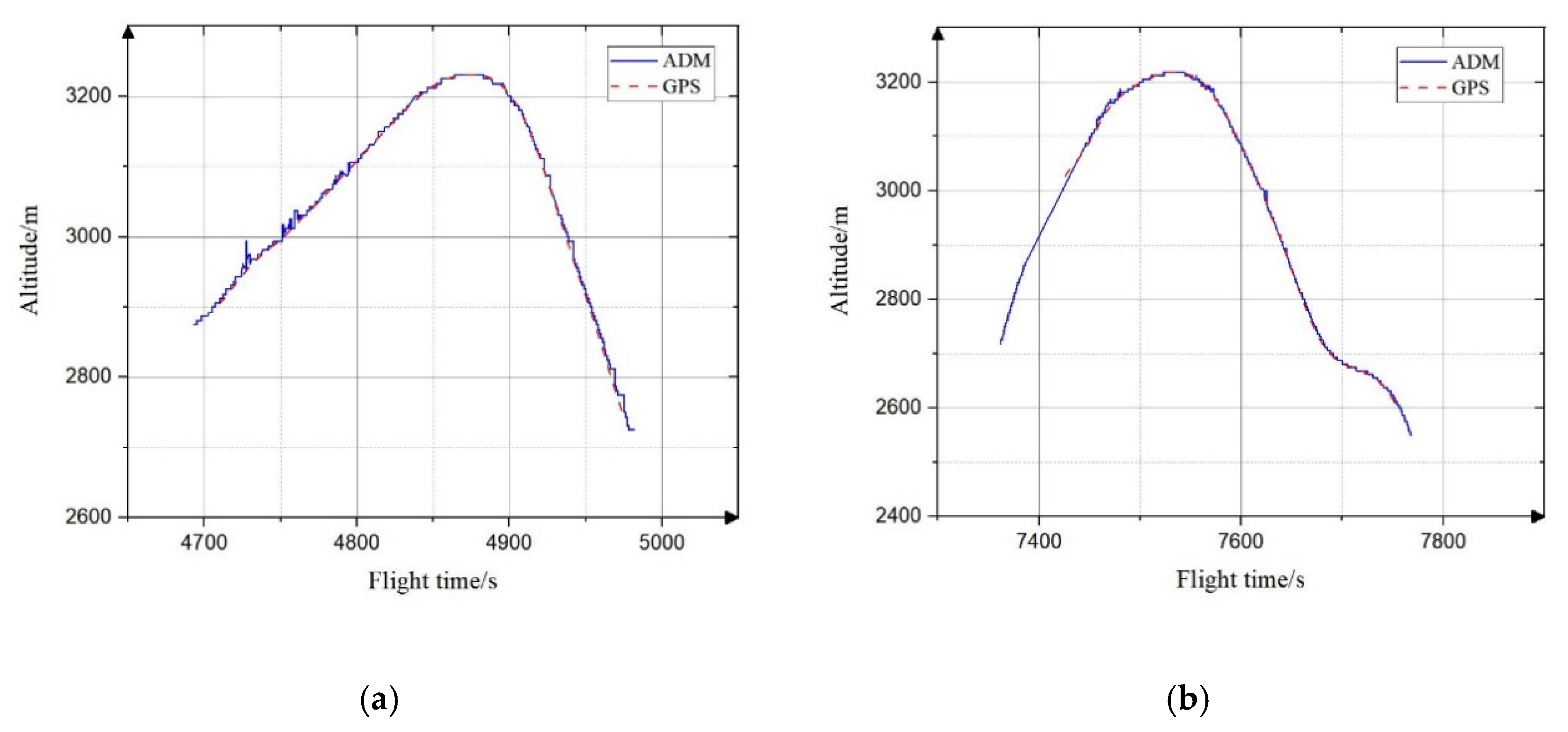
The corrected reference function is the dot product between the transmitting signal and the correction coefficient.
Figure 4 shows the range-compressed results of HFSS data in the ground experiment. The correction coefficient had been applied in the data processing, considering the antennas and Tx/Rx channels amplitude and phase compensation (Figure 4b). After range compression, the echo from the ground surface can be identified at the ~330th sampling point (Figure 4c).
The distance from the radar to the ground surface can convert from time delay by the following equation:
R ( x ) = 2500 + ( x 240 ) × 6.25 ,
where R(x) represents the distance between the radar and the sampling point, and the unit is meter; in the ground experiment, MOSIR begins to receive echoes 16.67 μs (2500 m in free space/atmosphere) after the pulse is transmitted, which should be taken into consideration. x represents the location of the sampling point we want to calculate. The transmitting signal’s length is 240 sampling points, corresponding to 10 μs sampling at 24 MHz. The subtracted term (240) comes from the principle of convolution, and the first 240 sampling points are of no practical significance. The distance between adjacent sampling points is 6.25 m, which two-way time interval is 1/(24 MHz) = 0.04167 μs.
Comparing the distance calculated from HFSS data with the reference height provided by GPS, error and standard deviation of the range-compressed result can be obtained by the following equation:
m k = 1 S k I k E q ,
σ k = 1 S k 1 I k ( E q m k ) 2 ,
where mk (m) represents the average error of the kth segment. σk is the standard deviation of the kth segment, which represents the dispersion of the error. Sk is the length of the kth segment of data and Eq (m) represents the error of each point between the altitude calculated from the mth data in the kth segment and the reference height. Ik represents the kth segment of data, segmented based on the distance. The error and standard deviation are used to evaluate the validity and accuracy of the range compression procedure.
In ADM mode, range compression has been accomplished onboard, and downlink data are the radar’s altitude. However, some null and wrong values (altitude values that deviate obviously from the correct value curve) occur. In order to obtain valid altitude measured values, we need to eliminate these invalid values. The accuracy of ADM mode is evaluated by comparing the ADM data with the reference height in the ground experiment.

4. Results

MOSIR collected one HFSS data block (including 142 data packages) and two valid ADM data blocks in the ground experiment. Each HFSS data package includes 32 columns of data. The total amount of the dataset is 4544 columns, which covers 26.613 s. With 4544 columns of HFSS data, the radar altitude curve measured in HFSS mode is calculated using Expression (6), as shown in Figure 5. With Expressions (7) and (8), the error and the standard deviation of HFSS data are obtained.
The calculation shows that the error between the altitude from HFSS data and the reference height is 9 m, and the standard deviation is 2.1 m. The error and standard deviation indicate that the result of range compression is accurate enough to verify the correctness of range compression flow.
Valid ADM data include two segments, which cover periods of 4693 s–4983 s (setting as period 1; Figure 6a) and 7362 s–7768 s (setting as period 2; Figure 6b), respectively. In period 1, the number of time sampling points is 5657, including 1652 points of null value (account for 29.2% of total) and 7 points of wrong value (account for 0.124% of total). In period 2, the number of time sampling points is 7836, including 2520 points of null value (account for 32.5% of total) and 28 points of wrong value (account for 0.357% of total). After removing these null and wrong values, we compare the ADM altitude curve with the reference altitude and calculate the error and the standard deviation.
In period 1, the average error of ADM altitude is 4.4 m, ranging from −7.7 m to 42.2 m, and the standard deviation is 6.5 m. In period 2, the average error of ADM altitude is 1.8 m, ranging from −6.9 m to 22.6 m, and the standard deviation is 3.9 m.
The ADM operating period contains the HFSS operating period (shown as Figure 1b), allowing for a comparison (Figure 5). The HFSS data covering period is 4934.9 s–4961.5 s. Calculating the error and standard deviation of ADM data collected simultaneously, ADM data’s average error is 9.6 m with the standard deviation of 4.7 m.

5. Discussion

The ground experiment has verified the performance of MOSIR for China’s first Mars exploration mission, Tianwen-1, in HFSS and ADM operating modes, the validity, and the accuracy of the data processing flow.
MOSIR collected dual-polarization echoes from the sub-satellite point in HFSS mode during the flight. Strong surface echo can be identified after range compression, and the peak strength of the surface echoes is usually ~40 dB higher than the background noise (as shown in Figure 4). After calculating the distance from time delay, the error and standard deviation of the range-compressed result exhibit high accuracy of the main lobe position, reaching the theoretical value of range resolution (7.5 m in free space) and confirming the validity of the range compression flow. Due to the flight restrictions and electromagnetic interference, we can only identify the strong surface echo, and azimuth processing (focusing) flow could not be verified with the several-hundred-meter flight distance.
In ADM mode, MOSIR processes received data on board and downlink altitude. During the flight, MOSIR obtained two altitude data blocks. The performance requirement of ADM altitude measurement accuracy is better than 10 m. The two periods’ error and standard deviation analysis meet the expected requirements. However, the ground elevation is generated by interpolation because of the terrain factor. The error still exists after terrain correction. The standard deviation of ground elevation is 0.6 m in period 1 and 1.3 m in period 2, indicating that the ground elevation interpolation error affects the accuracy of altitude measurement. The actual performance results should be better. After analysis, null and wrong values are possibly related to the complicated surface landform. The experimental area is close to the county, and interference caused by the broadcasting and other interference sources is intense and unpredictable. Interference intensity may be close to the surface echo so that the signal-to-noise ratio (SNR) cannot reach the criterion (>11 dB), and the peak detection program misidentifies or fails to identify. However, the ADM mode’s performance will dramatically improve with high operating orbits and a relatively clean electromagnetic environment in actual performance conditions.
We compare altitude measured by ADM mode to that of HFSS range-compressed results collected simultaneously. The comparison results show that the altitude measurement performance of HFSS and ADM modes is close.
Despite the experimental environment and conditions being different from Mars, the ground experimental results confirm that partial MOSIR operating mode and data processing flow satisfies the first Chinese Mars exploration mission, Tianwen-1. With the wide bandwidth of HFSS mode, MOSIR can map more fine-scale subsurface layering structures. The dual-polarization detection ability may play an important role in searching for ice/liquid water based on the terrestrial polarization radar sounding studies.

Author Contributions

Conceptualization, T.H., Y.S., M.F. and P.L.; methodology, T.H., Y.S., M.F. and P.L.; software, T.H.; writing—original draft preparation, T.H., Z.Z., R.W., C.L. (Chendi Liu), W.D. and S.L.; writing—review and editing, Y.S., C.D., T.H., C.L. (Chunlai Li) and S.D. All authors have read and agreed to the published version of the manuscript.

Funding

This research was funded by the National Natural Science Foundation of China (grant number 12073048) and by the Key Research Program, CAS (grant number ZDBS-SSW-JS007).

Institutional Review Board Statement

Not applicable.

Informed Consent Statement

Not applicable.

Acknowledgments

This work has been supported by the team “Searching for Subglacial Water on Mars with Orbiting Ground Penetrating Radars” of the International Space Science Institute (ISSI).

Conflicts of Interest

The authors declare no conflict of interest.

References

  1. Porcello, L.J.; Jordan, R.L.; Zelenka, J.S.; Adams, G.F.; Phillips, R.J.; Brown, W.E.; Ward, S.H.; Jackson, P.L. The Apollo lunar sounder radar system. Proc. IEEE 1974, 62, 769–783. [Google Scholar] [CrossRef]
  2. Zou, Y.; Zhu, Y.; Bai, Y.; Wang, L.; Jia, Y.; Shen, W.; Fan, Y.; Liu, Y.; Wang, C.; Zhang, A.; et al. Scientific objectives and payloads of Tianwen-1, China’s first Mars exploration mission. Adv. Space Res. 2021, 67, 812–823. [Google Scholar] [CrossRef]
  3. Li, C.; Liu, J.; Geng, Y.; Cao, J.; Zhang, T.; Fang, G.; Yang, J.; Shu, R.; Zou, Y.; Lin, Y. Scientific Objectives and Payload Configuration of China’s First Mars Exploration Mission. J. Deep Space Explor. 2018, 5, 406–413. [Google Scholar] [CrossRef]
  4. Wan, W.X.; Wang, C.; Li, C.L.; Wei, Y. China’s first mission to Mars. Nat. Astron. 2020, 4, 721. [Google Scholar] [CrossRef]
  5. Fan, M.; Lyu, P.; Su, Y.; Du, K.; Zhang, Q.; Zhang, Z.; Dai, S.; Hong, T. The Mars Orbiter Subsurface Investigation Radar (MOSIR) on China’s Tianwen-1 Mission. Space Sci. Rev. 2021, 217, 8. [Google Scholar] [CrossRef]
  6. Jol, H.M. Ground Penetrating Radar Theory and Applications; Elsevier: Amsterdam, The Netherlands, 2008; ISBN 9780080951843. [Google Scholar]
  7. Cumming, I.G.; Wong, F.H. Digital processing of synthetic aperture radar data. Artech House 2005, 1, 108–110. [Google Scholar]
  8. Seu, R.; Phillips, R.J.; Biccari, D.; Orosei, R.; Masdea, A.; Picardi, G.; Safaeinili, A.; Campbell, B.A.; Plaut, J.J.; Marinangeli, L.; et al. SHARAD sounding radar on the Mars Reconnaissance Orbiter. J. Geophys. Res. E Planets 2007, 112, E5. [Google Scholar] [CrossRef]
  9. Jordan, R.; Picardi, G.; Plaut, J.; Wheeler, K.; Kirchner, D.; Safaeinili, A.; Johnson, W.; Seu, R.; Calabrese, D.; Zampolini, E.; et al. The Mars express MARSIS sounder instrument. Planet. Space Sci. 2009, 57, 1975–1986. [Google Scholar] [CrossRef]
  10. Orosei, R.; Jordan, R.L.; Morgan, D.D.; Cartacci, M.; Cicchetti, A.; Duru, F.; Gurnett, D.A.; Heggy, E.; Kirchner, D.L.; Noschese, R.; et al. Mars Advanced Radar for Subsurface and Ionospheric Sounding (MARSIS) after nine years of operation: A summary. Planet. Space Sci. 2015, 112, 98–114. [Google Scholar] [CrossRef]
  11. Croci, R.; Seu, R.; Flamini, E.; Russo, E. The shallow RADar (SHARAD) Onboard the NASA MRO mission. Proc. IEEE 2011, 99, 794–807. [Google Scholar] [CrossRef]
  12. Seu, R.; Biccari, D.; Orosei, R.; Lorenzoni, L.V.; Phillips, R.J.; Marinangeli, L.; Picardi, G.; Masdea, A.; Zampolini, E. SHARAD: The MRO 2005 shallow radar. Planet. Space Sci. 2004, 52, 157–166. [Google Scholar] [CrossRef]
  13. Picardi, G.; Biccari, D.; Seu, R.; Marinangeli, L.; Johnson, W.T.K.; Jordan, R.L.; Plaut, J.; Safaenili, A.; Gurnett, D.A.; Ori, G.G.; et al. Performance and surface scattering models for the Mars Advanced Radar for Subsurface and Ionosphere Sounding (MARSIS). Planet. Space Sci. 2004, 52, 149–156. [Google Scholar] [CrossRef]
  14. Orosei, R.; Lauro, S.E.; Pettinelli, E.; Cicchetti, A.; Coradini, M.; Cosciotti, B.; Di Paolo, F.; Flamini, E.; Mattei, E.; Pajola, M.; et al. Radar evidence of subglacial liquid water on Mars. Science 2018, 361, 490–493. [Google Scholar] [CrossRef] [Green Version]
  15. Lauro, S.E.; Pettinelli, E.; Caprarelli, G.; Guallini, L.; Rossi, A.P.; Mattei, E.; Cosciotti, B.; Cicchetti, A.; Soldovieri, F.; Cartacci, M.; et al. Multiple subglacial water bodies below the south pole of Mars unveiled by new MARSIS data. Nat. Astron. 2021, 5, 63–70. [Google Scholar] [CrossRef]
  16. Stuurman, C.M.; Osinski, G.R.; Holt, J.W.; Levy, J.S.; Brothers, T.C.; Kerrigan, M.; Campbell, B.A. SHARAD detection and characterization of subsurface water ice deposits in Utopia Planitia, Mars. Geophys. Res. Lett. 2016, 43, 9484–9491. [Google Scholar] [CrossRef] [Green Version]
  17. Holt, J.W.; Safaeinili, A.; Plaut, J.J.; Head, J.W.; Phillips, R.J.; Seu, R.; Kempf, S.D.; Choudhary, P.; Young, D.A.; Putzig, N.E.; et al. Radar sounding evidence for buried glaciers in the southern mid-latitudes of Mars. Science 2008, 322, 1235–1238. [Google Scholar] [CrossRef] [Green Version]
  18. Plaut, J.J.; Safaeinili, A.; Holt, J.W.; Phillips, R.J.; Head, J.W.; Seu, R.; Putzig, N.E.; Frigeri, A. Radar evidence for ice in lobate debris aprons in the mid-northern latitudes of Mars. Geophys. Res. Lett. 2009, 36, 5–8. [Google Scholar] [CrossRef] [Green Version]
  19. Fois, F.; Croci, R.; Seu, R.; Picardi, G.; Flamini, E. Performance results of the SHARAD instrument. Int. Geosci. Remote Sens. Symp. 2007, 119–124. [Google Scholar] [CrossRef]
  20. Pirrotta, S.; Flamini, E. SoRa first flight. Summer 2009. Mem. Soc. Astron. Ital. Suppl. 2011, 16, 145. [Google Scholar]
  21. Watters, T.R.; Campbell, B.; Carter, L.; Leuschen, C.J.; Plaut, J.J.; Picardi, G.; Orosei, R.; Safaeinili, A.; Clifford, S.M.; Farrell, W.M.; et al. Radar sounding of the medusae fossae formation mars: Equatorial ice or dry, low-density deposits? Science 2007, 318, 1125–1128. [Google Scholar] [CrossRef] [Green Version]
  22. Campbell, B.; Carter, L.; Phillips, R.; Plaut, J.; Putzig, N.; Safaeinili, A.; Seu, R.; Biccari, D.; Egan, A.; Orosei, R. SHARAD radar sounding of the Vastitas Borealis Formation in Amazonis Planitia. J. Geophys. Res. E Planets 2008, 113, E12. [Google Scholar] [CrossRef] [Green Version]
  23. Cartacci, M.; Amata, E.; Cicchetti, A.; Noschese, R.; Giuppi, S.; Langlais, B.; Frigeri, A.; Orosei, R.; Picardi, G. Mars ionosphere total electron content analysis from MARSIS subsurface data. Icarus 2013, 223, 423–437. [Google Scholar] [CrossRef]
  24. Rahman, H. Pulse Compression Radar. Fundam. Princ. Radar 2019, 2, 131–154. [Google Scholar] [CrossRef]
  25. Fois, F.; Mecozzi, R.; Iorio, M.; Calabrese, D.; Bombaci, O.; Catallo, C.; Croce, A.; Croci, R.; Guelfi, M.; Zampolini, E. Comparison between MARSIS & SHARAD results. In Proceedings of the 2007 IEEE International Geoscience and Remote Sensing Symposium, Barcelona, Spain, 23–28 July 2007; pp. 2134–2139. [Google Scholar]
Figure 1. (a) The location of the MOSIR ground experiment area (the red cross). The experimental area is in Dengkou County of the Inner Mongolia Autonomous Region, China. (b) Satellite image of the experimental area and the flight track of MOSIR in the ground experiment (the red line). The yellow line represents the coverage of ADM data, and the blue one represents the coverage of HFSS data, in which ADM mode is also on.
Remotesensing 13 05049 g001
Figure 2. (a) Install location diagram of cross dipole antennas. Cross-dipole antennas are deployed in the +Z plane of the spacecraft. Therefore, the antenna plane is always directed toward Mars. (b) Hanging way of MOSIR and orbiter model, the distance between orbiter model and the balloon is 40.4 m. The wooden bracket is convenient for taking off and landing.
Remotesensing 13 05049 g002
Figure 3. (a) Time scheme of HFSS; (b) Time scheme of ADM in the ground experiment.
Remotesensing 13 05049 g003
Figure 4. (a) Real part of a column of HFSS raw data received in the ground experiment, length of data is 2280 sampling points; (b) Real part of correction coefficient for the ground experimental transmitting signal, the length is 4096 sampling points; (c) Part of the range-compressed result of (a), where the surface echo can be identified at the ~330th sampling point.
Remotesensing 13 05049 g004
Figure 5. Altitude measured by HFSS range-compressed data (the black cross), ADM altitude (the blue triangle), and the reference height provided by GPS (the red dot) at the same period.
Remotesensing 13 05049 g005
Figure 6. ADM valid data of (a) period 1 (4693 s–4983 s) and (b) period 2 (7362 s–7768 s). The Blue solid line represents ADM altitude, and the red dash line represents the reference height provided by GPS.
Remotesensing 13 05049 g006
Table 1. Main MOSIR parameters in the ground experiment.
ParameterValue
Central frequency40 MHz
Frequency bandwidth20 MHz
Transmitted power3 W
Pulse length10 μs
data time window95 μs (HFSS), 170 μs (ADM)
Operational altitude2500 m–3300 m
Total mass26 kg
Publisher’s Note: MDPI stays neutral with regard to jurisdictional claims in published maps and institutional affiliations.

