Article

Analysis of Hypersonic Platform-Borne SAR Imaging: A Physical Perspective

1
School of Aerospace Science and Technology, Xidian University, Xi’an 710071, China
2
Science and Technology on Space Physics Laboratory, Beijing 100076, China
3
School of Electrical & Electronic Engineering, Shandong University of Technology, Zibo 255000, China
*
Author to whom correspondence should be addressed.
Remote Sens. 2021, 13(23), 4943; https://doi.org/10.3390/rs13234943
Submission received: 22 November 2021 / Accepted: 29 November 2021 / Published: 5 December 2021

Abstract

:
The usage of a hypersonic platform for remote sensing application has promising prospects, especially for hypersonic platform-borne synthetic aperture radar (SAR) imaging. However, the high-speed of hypersonic platform will lead to extreme friction between the platform and air, which will cause the ionization of air. The ionized gas forms the plasma sheath wrapped around the hypersonic platform. The plasma sheath will severely affect the propagation of SAR signal and further affect the SAR imaging. Therefore, hypersonic platform-borne SAR imaging should be studied from a physical perspective. In this paper, hypersonic platform-borne SAR imaging under plasma sheath is analyzed. The SAR signal propagation in plasma sheath is computed using scatter matrix method. The proposed SAR signal model is verified by using a ground experiment system. Moreover, the effect of attenuation caused by plasma sheath on SAR imaging is studied under different SAR parameters and plasma sheath. The result shows that attenuation caused by plasma sheath will degrade the SAR imaging quality and even cause the point and area targets to be submerged into the noise. The real SAR images under plasma sheath also illustrate this phenomenon. Furthermore, by studying imaging results under different SAR and plasma parameters, it can be concluded that the severe degradation of SAR imaging quality appears at condition of high plasma sheath electron density and low SAR carrier frequency. The work in this paper will be beneficial for the study of hypersonic platform-borne SAR imaging and design of hypersonic SAR imaging systems in the future.

Graphical Abstract

1. Introduction

Hypersonic platform-borne synthetic aperture radar (SAR) imaging has a promising application prospect [1,2,3,4,5]. The hypersonic platform-borne SAR works at a typical altitude between 20 and 100 km with a speed over Mach 5 [6,7]. Due to its strong survival ability, fast response, and wide detection range characteristics, hypersonic platform-borne SAR imaging has its unique advantages over airborne [8,9,10] or spaceborne [11,12,13] SAR. One of most important applications is hypersonic platform-borne SAR imaging.
As hypersonic platform-borne SAR imaging plays an important role in civilian and military fields, many researchers studied it from different aspects [1,2,3,4,5,14,15]. For range migration and pulse broadening phenomenon caused by the “scale effect” which will lead to the decrease of SAR imaging resolution, Xu [3] proposed the corresponding compensating factors in matched filleter to solve this problem. Han [4] proposed a robust clutter suppression and detection of ground moving target (GMT) imaging method for a multichannel hypersonic-vehicle borne synthetic aperture radar (MC- HSV-SAR) with high-squint angle. Aiming at cross-couplings and spatial variations problems in hypersonic platform-borne SAR imaging with squint angle, Tang [1] proposed a radius/angle algorithm which can obtain better focus depth. Many other researchers [14,15] also conducted the study of hypersonic platform-borne SAR imaging from different views.
However, the previous studies mainly focus on high speed and high maneuverability problems for hypersonic platform-borne SAR imaging. In fact, a unique physical phenomenon has been observed when the hypersonic platforms fly at hypersonic speed. Due to extreme speed, the air near the hypersonic platform will be compressed and then the air is ionized. Many particles form a special plasma layer called plasma sheath [16,17]. The plasma sheath is a complex medium [18], which will bring significant influence on the propagation of SAR signals. Consequently, the SAR imaging characteristics would be changed under plasma sheath. Therefore, the hypersonic platform-borne SAR imaging should be studied from the physical perspective. The SAR signal model under plasma sheath should be established and verified, and the effect of plasma sheath on hypersonic platform-borne SAR imaging should be clarified.
The study of SAR signal model under plasma sheath is a new problem and is fundamental for hypersonic platform-borne SAR imaging. Recently, a number of studies [19,20,21,22,23,24,25,26,27,28] on the signal propagation through plasma sheath were conducted. The reflection and transmission characteristics of sine waves [19,20,21,22,23] propagating through plasma sheath are analyzed in detail. Moreover, the depolarization effect of sine signals propagating in plasma sheath is further studied [24,25]. For quadrature phase-shift keyed signals (QPSK) signal, Yang [26,27] proposed the computation method for QPSK signal propagation in plasma sheath. However, the sine and QPSK signal are not common for SAR systems. Many studies examine the radar detection of hypersonic target enveloped by plasma sheath [28,29]. The RCS [30,31] and the one-dimension range profile [32,33] of hypersonic target covered by plasma sheath are explored and false target phenomenon is found. However, radar detection of hypersonic target enveloped by plasma sheath is quite different from the study in this paper. For the study in [28,29], the radar signal is reflected by plasma sheath and the reflection effect caused by plasma sheath is coupled into the radar signal. While in this study, the SAR signal propagates through plasma twice and the transmission effect caused by plasma sheath is coupled into the SAR signal.
Therefore, in this study, hypersonic platform-borne SAR signal model under plasma sheath is established theoretically and verified experimentally. Then the effect of attenuation characteristics caused by plasma sheath on SAR imaging is analyzed. The main contributions of this paper are as follows:
  • Based on the hypersonic platform-borne SAR signal propagation characteristics under plasma sheath, the hypersonic platform-borne SAR signal model is established. The transmission coefficient for SAR signal propagating through plasma sheath is computed by scatter matrix method. Furthermore, because the hypersonic platform-borne SAR signal propagates through the plasma sheath twice, the double transmission effect is coupled in the SAR signal model.
  • By building a ground experiment system, SAR signal model under plasma sheath is verified experimentally. The plasma is produced by low-pressure glow discharge plasma generator. By comparing the theoretical and experimental results of time domain, frequency domain, and range compressed signal, the SAR signal model under plasma sheath is verified. From the theoretical and experimental results, it can be found that the plasma sheath will bring significant amplitude attenuation of SAR signal, which will cause the decrease of peak value of range compressed signal. This phenomenon is important and will significantly affect SAR imaging quality.
  • The effect of attenuation characteristics caused by plasma sheath on SAR imaging is studied, and the key factors determining the SAR imaging quality are explored. The point target and the area targets imaging results under plasma sheath show that large attenuation will cause the focus depth decrease and even cause the target response to be submerged in the noise. In addition, by studying the key factors determining the SAR imaging quality under plasma sheath, it can be concluded that the severe degradation of SAR imaging appears at condition of high plasma sheath electron density and low SAR carrier frequency.
The paper is arranged as follows. In Section 2, the role of plasma sheath in hypersonic platform-borne SAR imaging is introduced firstly. Then the hypersonic platform-borne SAR signal model under plasma sheath is established based on scatter matrix method. In addition, the experiment system for SAR signal propagating through plasma sheath is built and the signal model under plasma sheath is verified by the comparison of theory and experiment result. In Section 3, point target and area targets response under plasma sheath are analyzed and the key factors determining the SAR imaging quality under plasma sheath are explored. Section 4 provides the conclusion.

2. Model and Experiment

2.1. Introduction of Hypersonic Platform-Borne SAR Imaging under Plasma Sheath

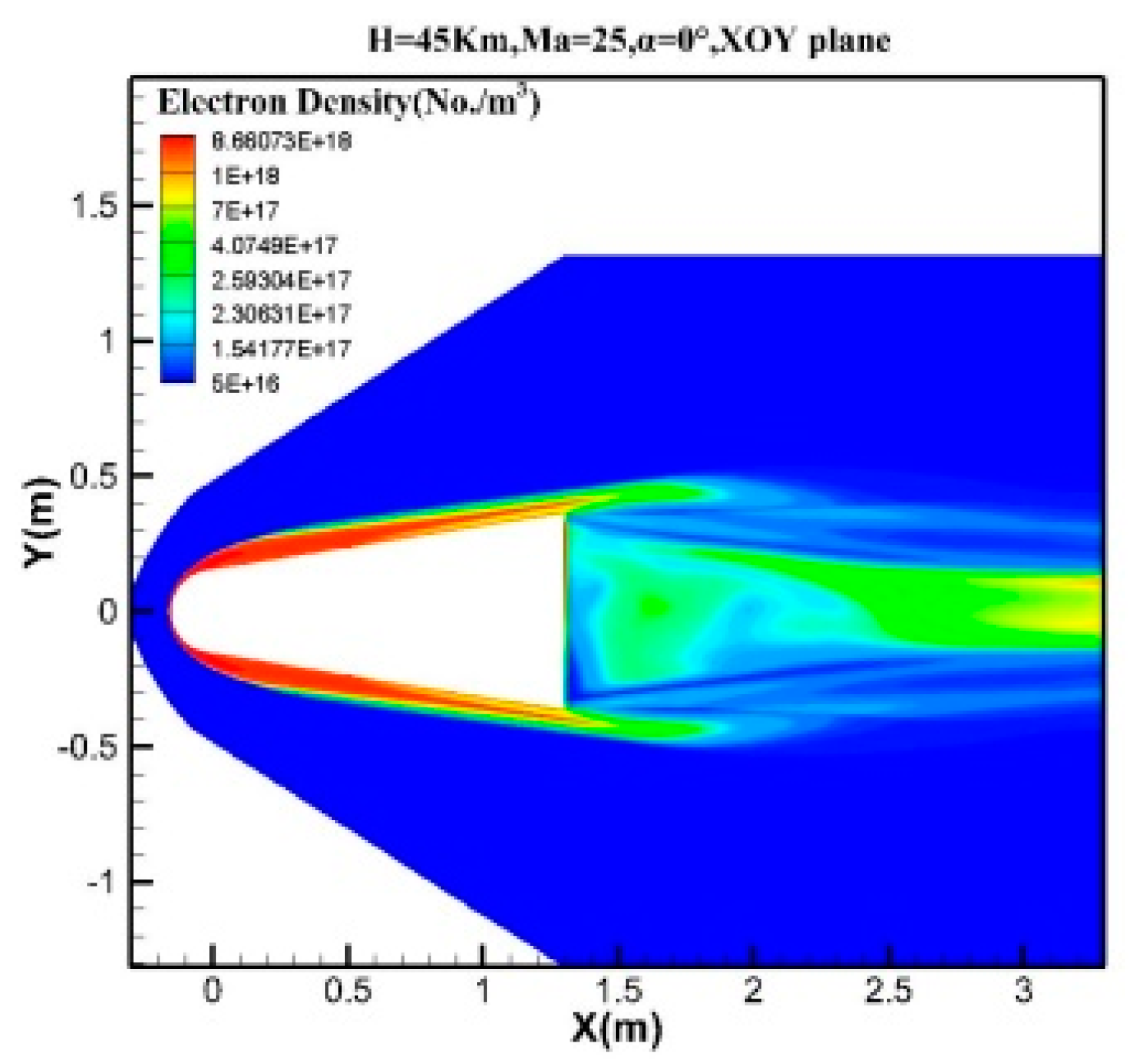
When the hypersonic platform flies at hypersonic speed, the air around the hypersonic platform is strongly compressed. Therefore, because the temperature and pressure are very high, the air will dissociate and ionize, and many charged free electrons and positive ions are formed. These particles form a plasma sheath covering the surface of the platform. Figure 1 is the schematic diagram of flow field when hypersonic platform flies. As shown in Figure 1, the plasma sheath envelopes the hypersonic platform. Figure 2 is the flow field simulation result under a typical flight condition. According to the flow field simulation data of the hypersonic platform under different conditions, the plasma sheath will be produced when flying height is between 30 and 70km, and flying speed is greater than 15Mach. Under these circumstances, the electron density has a large distribution range varying from 1 × 10¹⁶/m3 to 1 × 10¹⁹/m3.
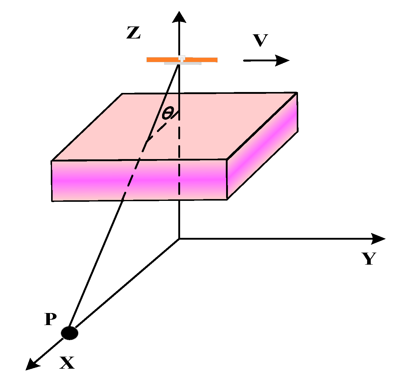
For the plasma sheath near the antenna, the plasma sheath has a specific distribution perpendicular to the surface of the platform. Figure 3 shows the plasma sheath near the antenna. The side-looking SAR imaging is adopted here to conveniently illustrate the plasma sheath effect in SAR imaging, and the “scale effect” can be ignored when squint angle is small. From Figure 3, compared with traditional SAR imaging, the biggest feature of hypersonic platform-borne SAR imaging is that the SAR signal will pass through the plasma sheath twice. After SAR signal is emitted from the antenna, the SAR signal will firstly propagate through the plasma sheath. The SAR signal will be reflected by the target in the scene and will secondly propagate through the plasma sheath before receiving by antenna. The plasma sheath is a kind of complex media, and the SAR signal characteristics will change when propagating through plasma sheath. The distorted SAR signal will cause the change of SAR imaging characteristics, which should be further analyzed.

2.2. Hypersonic Platform-Borne SAR Signal Model Coupling Plasma Sheath Effect

During the hypersonic flight, the friction between hypersonic platform and air will cause the high temperature and pressure of air, which will lead to the ionization of air, and plasma sheath forms. Based on [16], the distribution of plasma sheath follows the bi-Gauss distribution, and is shown as follows
N e ( z ) = { N e p e a k exp [ c 1 ( z z p e a k ) 2 ] ( 0 z z p e a k ) N e p e a k exp [ c 2 ( z z p e a k ) 2 ] ( z > z p e a k )
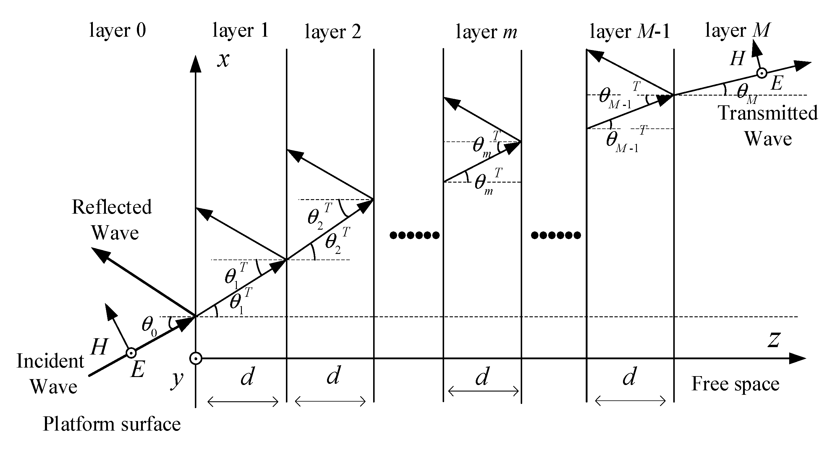
The parameters c1 and c2 represent the shape of the distribution of electron density vertically on the platform surface. Nepeak is the maximum density and zpeak is the location of peak electron density. The plasma sheath can be approximately divided into a series of adjacent homogeneous thin plasma layers. The distribution of plasma sheath is shown in Figure 4.
As shown in Figure 3, assuming a target P whose coordinate is p exists in the scene, the instantaneous slant range from the radar to the target can be expressed as
R ( t a ; p ) = P ( t a ) p 2
where P ( t a ) is the position of SAR at slow time t a , 2 indicates the 2-norm.
With a given pulse repetition frequency, the SAR emits a linear frequency modulation signal which can be expressed as
s ( t r ) = r e c t ( t r / T p ) · exp [ j 2 π ( f c t r + γ t r 2 / 2 ) ]
where tr is fast time, T p is the pulse width, f c is carrier frequency, and γ is the frequency modulation rate. If without plasma sheath, after being reflected by the target P in the scene, the echo can be written as
s ( t r , t a ; p ) = α p · w r ( t r ) · w a ( t a ) · exp [ j 2 π ( f c ( t r τ ) + γ ( t r τ ) 2 / 2 ) ]
α p is the scattering intensity, w r ( t r ) is window in the range direction which can be expressed as w r ( t r ) = rect [ ( t r τ ) / T p ] , w a ( t a ) is the window in azimuth direction. τ is the two-way delay and is written as
τ = 2 R ( t a ; p ) / c
where c is the light speed.
After converting to baseband, the SAR signal is
s ( t r , t a ; p ) = α p · w r ( t r ) · w a ( t a ) · exp [ j 2 π ( - f c τ + γ ( t r τ ) 2 / 2 ) ]
When plasma sheath presents, the plasma sheath effect should be coupled into the SAR signal model. The SAR signal under plasma sheath is written as
s p l a s m a ( t r , t a ; p ) = α p · w a ( t a ) · exp [ j 2 π f c τ ] · i f f t [ W r ( f r ) · p ( f r ) · T 2 ( f r ) ]
where T ( f r ) is the transmission coefficient for SAR signal propagating through plasma sheath. Due to the double transmission for SAR signal, the transmission coefficient T ( f r ) in (7) is multiplied twice. The p ( f r ) is the Fourier transform of exp [ π γ ( t r τ ) 2 ) ] .
In addition, the range compressed SAR signal under plasma sheath will be further studied to illustrate the plasma sheath effect on SAR imaging. For simplifying the analysis and focusing on the plasma sheath effect, the side-looking SAR is adopted here. The R ( t a ; p ) can be approximated as
R ( t a ; p ) = R 0 2 + V 2 t a 2 R 0 + V 2 t a 2 2 R 0
where V and R0 are the platform velocity and minimum slant range, respectively. By applying the principle of stationary phase (POSP), the range compressed SAR signal without plasma sheath can be written as
s ( f r , t a ; p ) = α p · W r ( f r ) · w a ( t a ) · exp ( j π K a t a 2 ) exp ( j 2 π f r · 2 R ( t a ; p ) c )
where K a = 2 V 2 / λ R 0 . When plasma sheath appears, the range compressed signal coupling plasma sheath effect can be written as
s r c , p l a s m a ( t r , t a ; p ) = α p · w a ( t a ) · exp ( j π K a t a 2 ) i f f t [ W r ( f r ) · T 2 ( f r ) · exp ( j 2 π f r · 2 R ( t a ; p ) c ) ]
It can be obtained from (10) that for different t a , the plasma sheath effect is the same. The computation of T ( f r ) is critical point, which will be illustrated below.
As shown in Figure 5, the electric field in mth layer can be written as
E m = e y E 0 ( B m e j k m ( sin θ m x + cos θ m z ) + C m e j k m ( sin θ m x cos θ m z ) )
where B m is the reflection coefficient in mth layer, and C m is transmission coefficient. km is wave number, and reads
k m = ω μ 0 ε 0 ε ˜ r , m
μ 0 and ε 0 shown in Equation (12) are permeability and dielectric constant in free space. ω is the angular frequency which can be expressed as ω = 2 π f , and f is frequency. ε ˜ r , m is the relative dielectric constant of mth layer
ε ˜ r , m = ( 1 ω p , m 2 ω 2 + ν 2 j ω p , m 2 ν / ω ω 2 + ν 2 ) ε 0
where ν is the collision frequency. The ω p , m in (13) is plasma frequency which can be written as
ω p , m = N e , m e 2 ε 0 m e
In Equation (14), e is the electron charge and m e is the electron mass. N e , m is the value of electron density for mth layer of plasma sheath. The magnetic field in mth layer is H m which reads
H m = 1 η m E 0 B m ( - e x cos θ m + e z sin θ m ) e j k m ( sin θ m x + cos θ m z ) + 1 η m E 0 C m ( e x cos θ m + e z sin θ m ) e j k m ( sin θ m x cos θ m z )
η m and θ m are wave impedance and incident angle in mth layer, respectively. According to the boundary condition for the mth layer, it can be obtained that
( B m C m ) = S m ( B m 1 C m 1 )
where the scatter matrix S m can be expressed as
S m = ( 1 1 k m cos θ m k m cos θ m ) 1 × ( e j d k m 1 cos θ m 1 e j d k m 1 cos θ m 1 k m 1 cos θ m 1 e j d k m 1 cos θ m 1 k m 1 cos θ m 1 e j d k m 1 cos θ m 1 )
By applying the boundary condition for the Mth layer (the rightmost air layer), it can be derived that
Q · R = S g ( 1 T )
where S g can be written as cascade of scatter matrix for each layer
S g = m = M 1 1 S m
The Q in (18) is
Q = 1 2 k M 1 cos θ M 1 ( ( k M 1 cos θ M 1 + k M cos θ M ) e j k M 1 cos θ M 1 d ( k M 1 cos θ M 1 k M cos θ M ) e j k M 1 cos θ M 1 d )
The matrix S g can be rewritten as
S g = [ S g 1 S g 2 ]
The total transmission and reflection coefficient read
( T R ) = - ( S g 2 - Q ) 1 S g 1
where T is the transmission coefficient, and R is the reflection coefficient. The transmission coefficient T depends on the frequency and plasma sheath parameters. When calculating the transmission coefficient of a plasma sheath, the plasma sheath parameters are given and transmission coefficient can be written as T(f) which is a function of frequency. By applying T(f) into Equations (7) and (10), the SAR signal model under plasma sheath is established. The transmission coefficient T(f) will lead to the significant effect on SAR imaging quality, which will be studied experimentally and theoretically in the following.

2.3. Experimental Verification of the SAR Signal Model under Plasma Sheath

In Section 2.2, we established the SAR signal model under plasma sheath. In this section, the ground experiment verification of SAR signal model under plasma sheath is conducted. Based on Equation (10), the plasma sheath mainly affects the range dimension, and plasma sheath effects are the same for different slow time t a . In addition, the SAR signal will doubly propagate through plasma sheath based on Equations (7) and (10). As the transmission coefficient for SAR signal passing through the plasma sheath at emission and receiving period is calculated using the same method, we couple the one-way transmission coefficient into the signal model, and if characteristic of SAR signal coupling one-way transmission coefficient is verified, the SAR signal coupling two-way transmission coefficient will be also validated. Therefore, the SAR signal propagating through plasma sheath and the corresponding range compression result are investigated experimentally and theoretically. Specifically, the time and frequency domain characteristics of SAR signal coupling plasma sheath effect and range compressed result under plasma sheath are studied experimentally in this section to verify the signal model under plasma sheath.
The purpose of experiments in this paper is to verify the signal model established in Section 2.2 under plasma sheath. The scatter matrix method is used for establishing the signal model, and this method can compute the wave propagation through the plasma sheath at microwave band. Therefore, as long as we choose the carrier frequency at microwave band, the scatter matrix method is appropriate for computing the transmission coefficient coupled in Equation (10), and the carrier frequency at microwave band can be selected for the experiment on verifying the signal model. In addition, the condition that carrier frequency is close to plasma frequency is a critical condition. If the carrier frequency is larger than the plasma frequency, the plasma sheath has a slight effect on the radar signal. However, if the carrier frequency is close to or smaller than the plasma frequency, the attenuation characteristics caused by plasma sheath will be severe. Therefore, it is necessary to verify the signal model and study the signal characteristics in the experiment at critical condition when carrier frequency is close to plasma frequency. Here, we choose the signal carrier frequency at microwave band as 1.4 GHz which is able to verify the signal model. The electron density we choose is 2.2 × 10¹⁶/m3 whose plasma frequency is near the carrier frequency, and the purpose is to reproduce the situation in which serious attenuation happens when carrier frequency is close to plasma frequency. This situation is common due to a large varying range of plasma sheath electron density, and it deserves to be discussed in detail. This is reason why we chose the selected experimental parameters in this section.
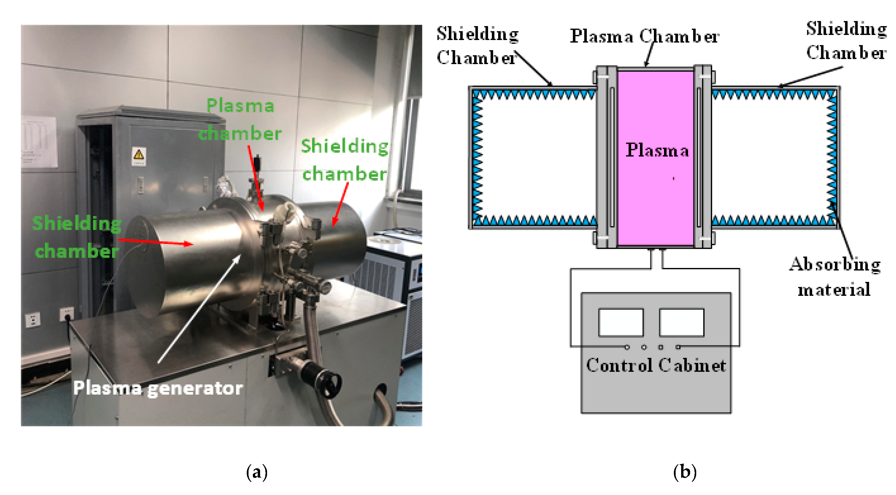
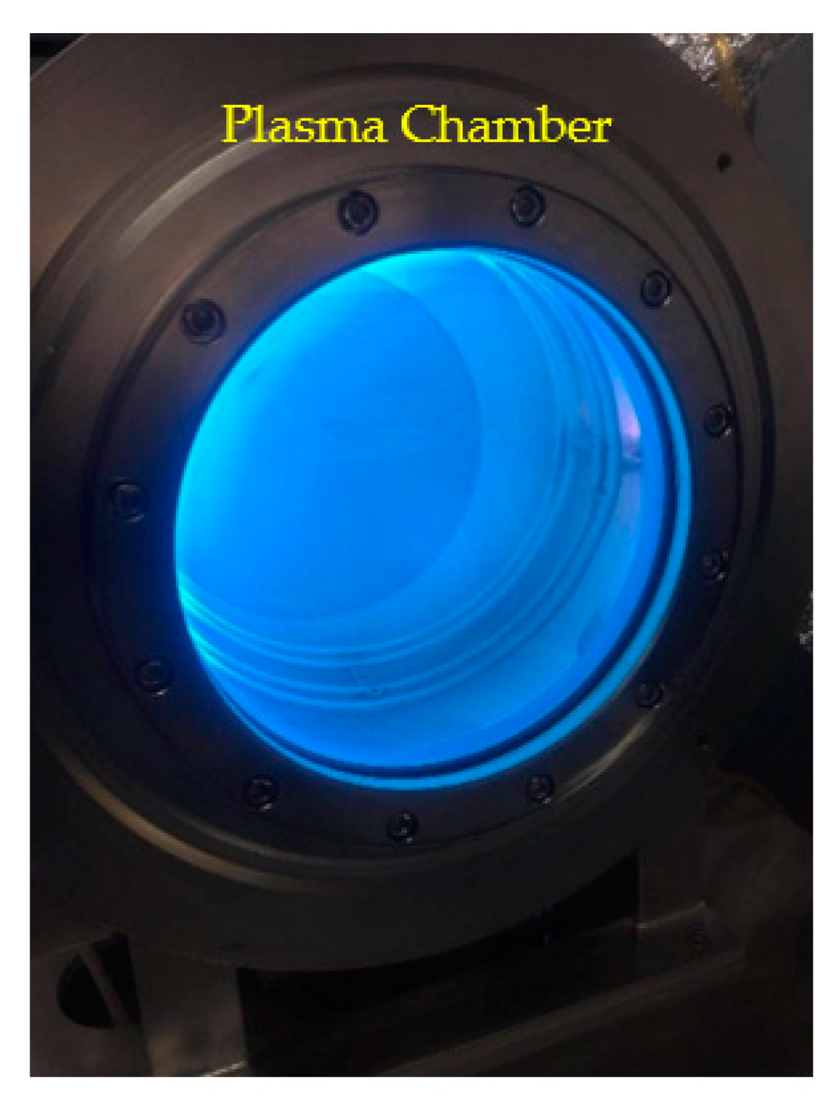
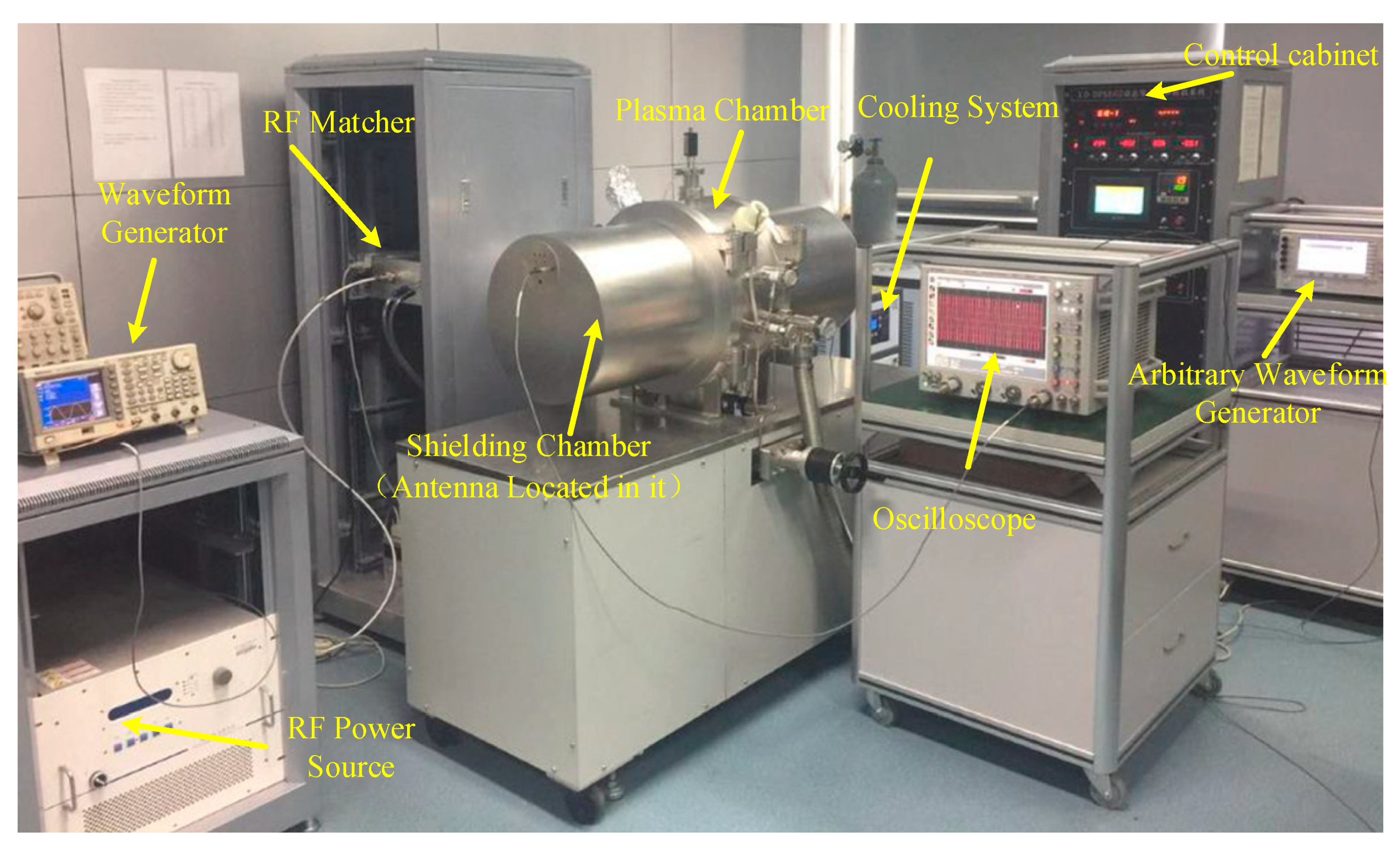
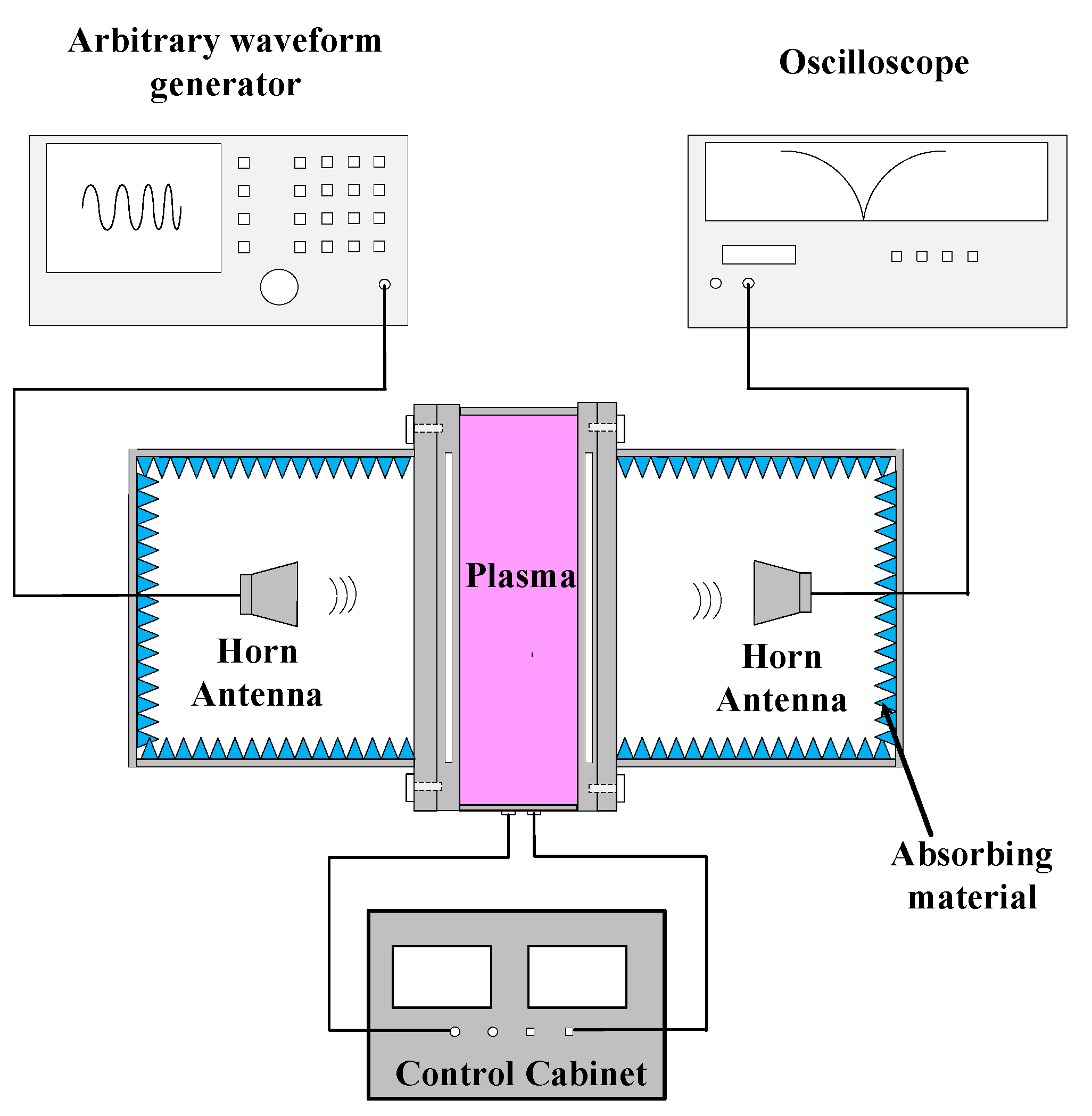
The outline of the experimental setup is as follows. The plasma generator is shown in Figure 6. The photo of plasma generator is shown in Figure 6a and schematic diagram is shown in Figure 6b. The equipment used in this experiment is a low-pressure glow discharge plasma generator. The plasma chamber is a stainless steel hollow cylinder with a radius of 400 mm and a length of 240 mm. The produced plasma is shown in Figure 7. At both ends of the plasma chamber, there are two wave transmission windows. These two windows are made of quartz glass which can hardly affect the wave propagation. Two shielding chambers equipped with absorbing materials are installed outside the wave transmission window. This plasma generator is capable of generating a uniform, large-scale, controllable plasma for SAR signal propagation experiment. The control cabinet can set the input power. By changing the power level of the input power, different electron densities can be achieved. The electron density can be measured by a double Langmuir probe. Therefore, by measuring the electron density of plasma at each input power, the relationship of input voltage versus the electron density can be obtained. Through this relationship, we can get the electron density of plasma in the experiment. An overview of experiment configuration is shown in Figure 8. The schematic diagram of SAR signal passing through plasma is shown in Figure 9. The SAR signal is produced by arbitrary waveform generator, and then transmitted by a horn antenna. The SAR signal propagates through the plasma and then is received by another horn antenna. Finally, the SAR signal coupling the plasma sheath effect is received by the oscilloscope.
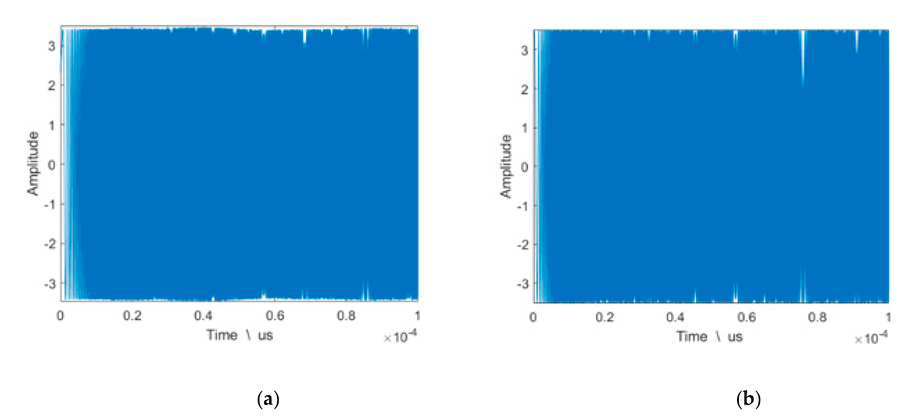
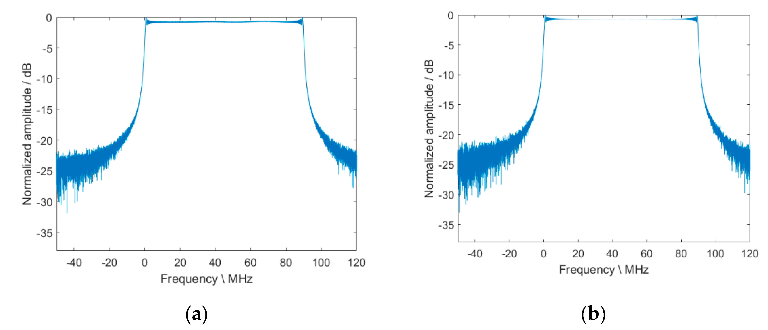
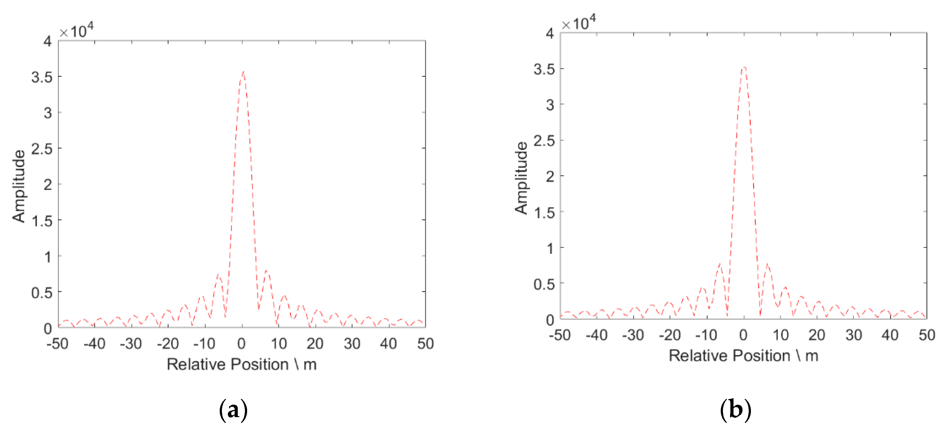
Based on Equation (10), for different slow time t a , the plasma sheath effect is the same. Therefore, theoretical and experimental results of the signal waveform, spectrum, and SAR signal range compression results with and without plasma sheath at a given slow time t a are shown in Figure 10, Figure 11, Figure 12, Figure 13, Figure 14 and Figure 15. The carrier frequency of SAR signal used in the experiment is 1.4 GHz. The pulse width and bandwidth of SAR signal are 100 μs and 90 MHz, respectively. For the theoretical signal without plasma sheath shown in Figure 10b, the amplitude of the theoretical signal is set to be the same as the average amplitude of the experimental signal waveform which is shown in Figure 10a. This is because the amplitude of experimental signal waveform has slight fluctuation. However, this slight fluctuation would not affect the subsequent experiment. The signal frequency spectrum without plasma sheath is shown in Figure 11 which is normalized to its maximum value. Furthermore, by adjusting the phase characteristics of theoretical signal to obtain the same range compressed signal characteristics with experimental result shown in Figure 12a, the phase characteristics of theoretical and experimental signal can be considered the same.
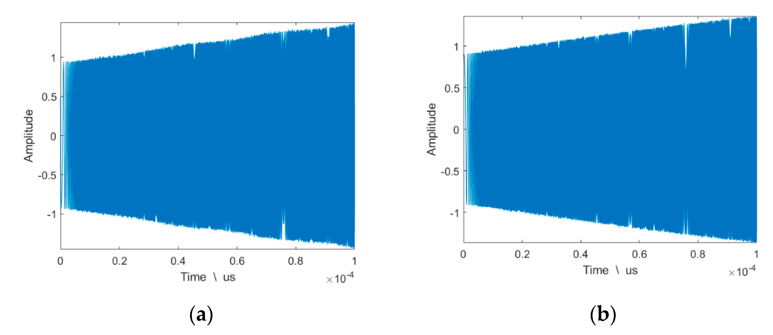
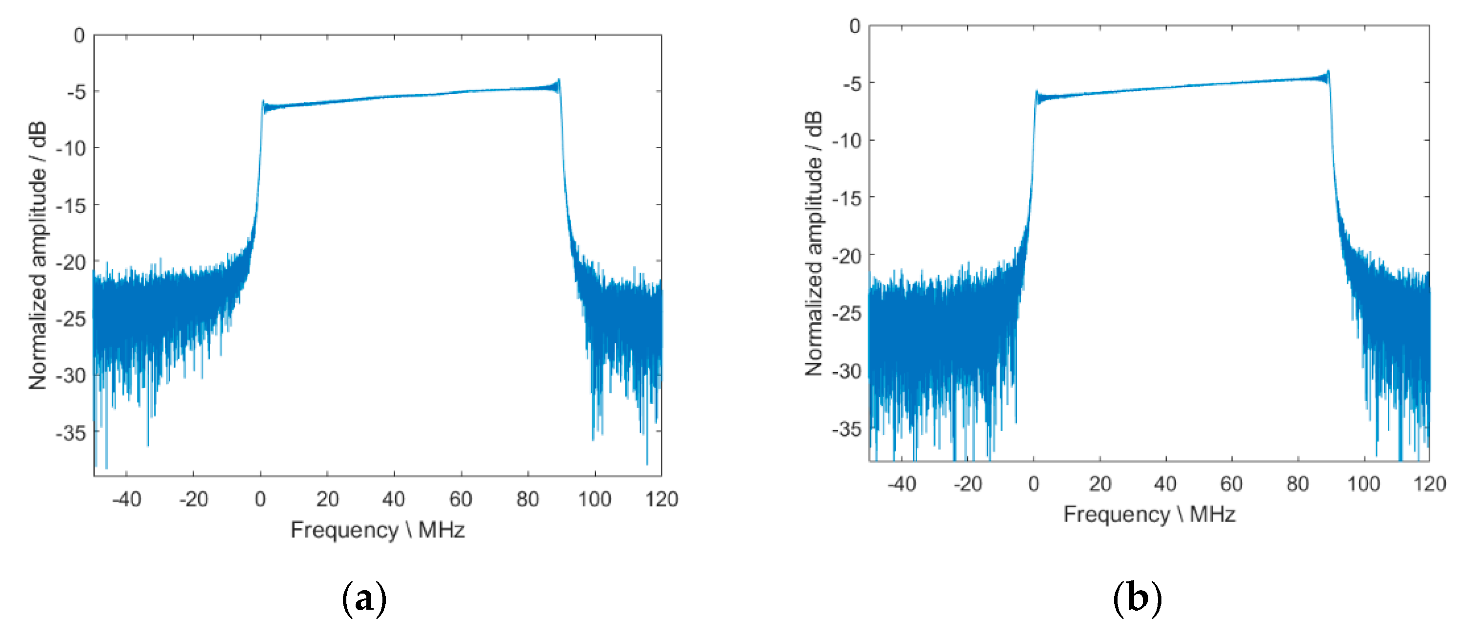
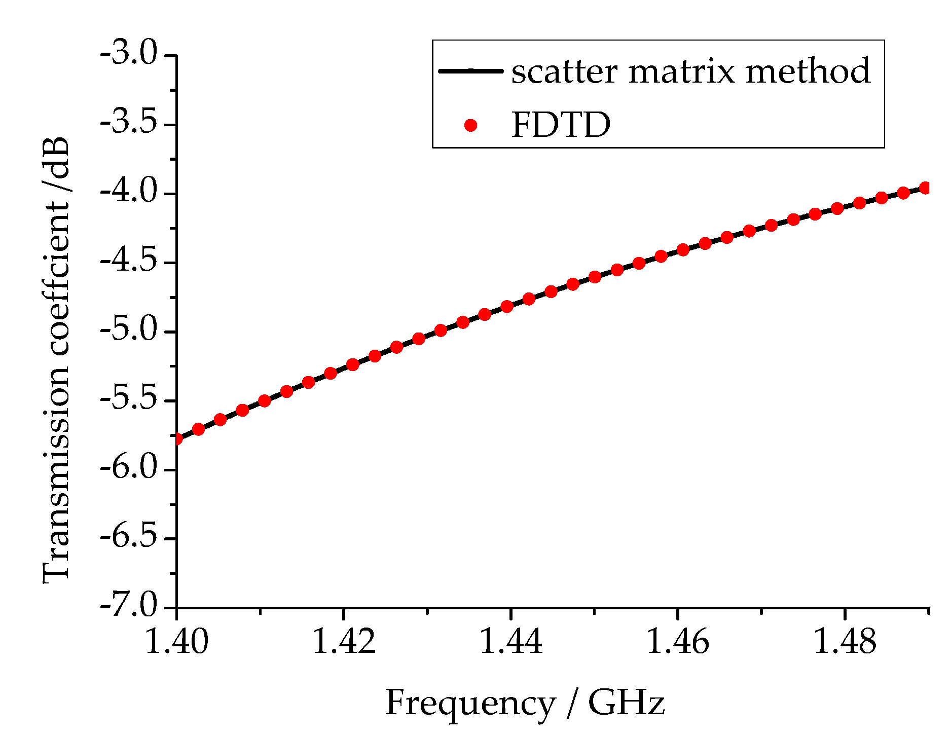
After SAR signal propagating through the plasma, the experiment results of signal waveform, spectrum and range compression result are shown in Figure 13a, Figure 14a and Figure 15a. The corresponding theoretical results with plasma sheath are computed using signal model shown in Section 2.2, and the theoretical results are displayed in Figure 13b, Figure 14b and Figure 15b. The electron density used for computing the theoretical results is obtained based on the relationship between electron density and setting power level. The electron density in this experiment is 2.2 × 10¹⁶/m3. As shown in Figure 13, the signal waveforms of theory and experiment in time domain are similar. It can be found that the SAR signal shows an upward trend in time domain. The frequency spectrum of signal after down conversion in Figure 14 also shows the same trend. The frequency spectrum in Figure 14 is normalized to a maximum value of amplitude of spectrum without plasma. This phenomenon is closely related to the transmission coefficient shown in Figure 16. As the transmission coefficient of the EM wave in high frequency is larger than that in low frequency, the transmission coefficient shows an upward trend. Based on Equation (10), the transmission coefficient T ( f r ) of SAR signal is coupled into the SAR signal model under plasma sheath. Therefore, the envelope of SAR signal with plasma will also show an upward trend. The transmission coefficient T ( f r ) is key factor determining the signal characteristics. In order to further illustrate the correctness of signal model, the computing result of transmission coefficient T ( f r ) using scatter matrix method and FDTD method are compared in Figure 16, and their results are similar. Therefore, the signal model coupling transmission coefficient computed by scatter matrix method is credible based on theoretical and experiment results.
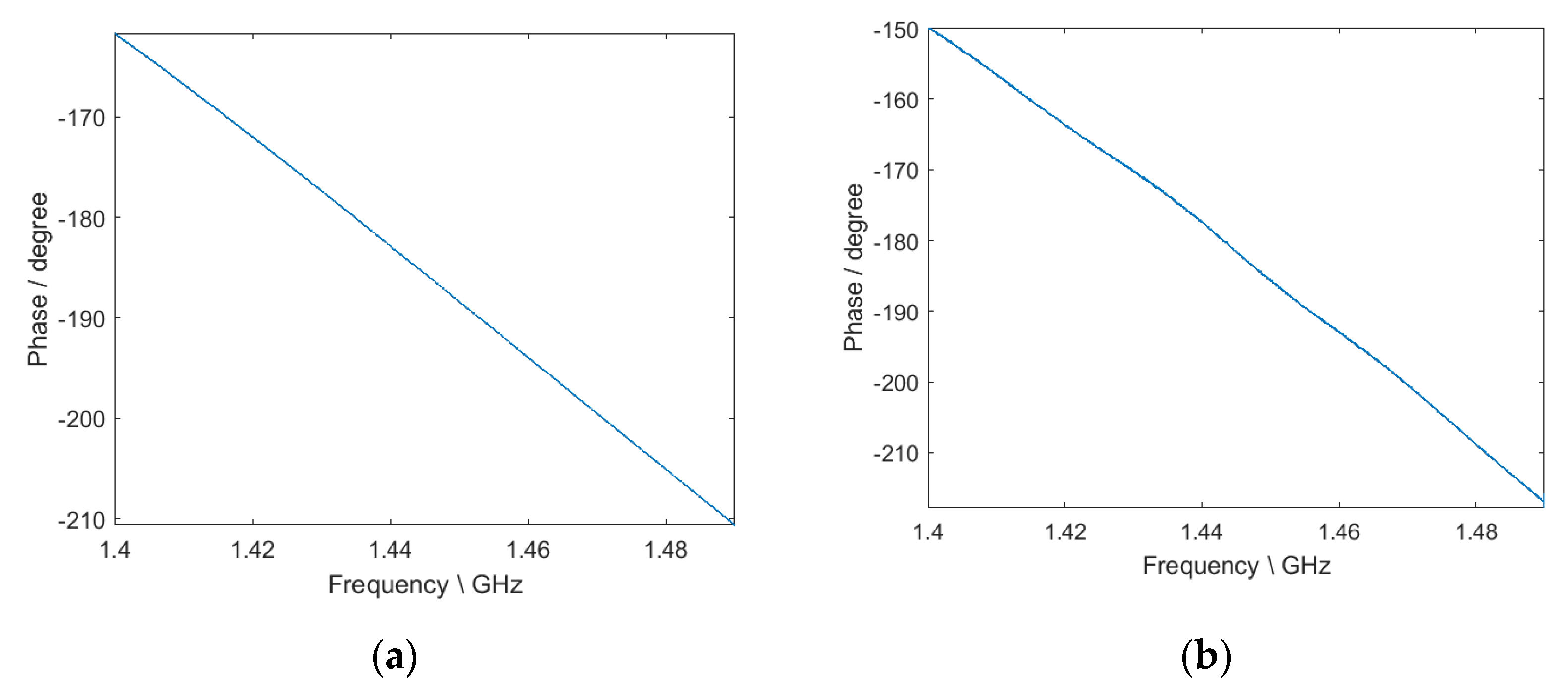
In addition, for the range compressed result, the most remarkable feature is that amplitude of range compressed signal with plasma significantly decreased compared with the result without plasma sheath. The reason for this phenomenon is the attenuation caused by plasma sheath. More specifically, if without plasma, the peak value of range compressed signal is about 3.5 × 10⁴ shown in Figure 12. The amplitude of signal waveform without plasma in time domain is about 3.5 shown in Figure 10. However, when plasma presents, the signal suffers from serious attenuation. The amplitude attenuation of transmission coefficient in bandwidth is more than −4 dB based on Figure 16. Therefore, the average amplitude of signal with plasma in time domain shown in Figure 13 is near 1.2 which is much smaller than the amplitude of signal without plasma. The spectrum with plasma sheath shown in Figure 14 also indicates an amplitude attenuation over −4 dB. As a result, after range compression, the peak value of range compressed signal with plasma sheath shown in Figure 15 decreases to 1 × 10⁴. Moreover, the plasma sheath will cause the additional phase shift for the SAR signal. However, the phase shift caused by the plasma sheath is relatively small, and it has little effect on range compression. The specific analysis is as follows. The theoretical phase shift within the bandwidth shown in Figure 17a is obtained by calculating the phase characteristics of transmission coefficient. The experiment phase characteristics within signal bandwidth are obtained by measuring phase shift of broadband signal propagating through plasma, and the result is shown in Figure 17b. It can be found that the phase varies about 45° within the bandwidth in the theoretical result and about 65° in the experiment result. The phase variation within the bandwidth is so small that it hardly causes the range dimension distortion.

3. Results and Discussion

This part will firstly discuss the point target and area targets response under plasma sheath. Furthermore, the attenuation caused by plasma sheath will seriously affect the range compressed result and further affect SAR imaging quality. Therefore, the key factors affecting the SAR imaging quality under plasma sheath will be further studied.
As the value of electron density of plasma sheath has a large varying range, for a specific carrier frequency, the conditions including that carrier frequency is larger than the plasma frequency, the carrier frequency is close to the plasma frequency, and the carrier frequency is smaller than the plasma frequency will probably happen. The plasma frequency is obtained in Equation (14). The SAR signal characteristics will be different under these three conditions, and the influence of plasma sheath on SAR imaging will be also different under these circumstances. Therefore, the study of SAR imaging under these three different conditions should be conducted. The selected carrier frequency for SAR is 10.5 GHz in following point and area target analysis. The selected electron densities are 1 × 10¹⁷/m3, 1 × 10¹⁸/m3, and 2 × 10¹⁸/m3, and the corresponding plasma frequencies are less than, equal to, or greater than the carrier frequency (10.5 GHz), respectively. For hypersonic platform-borne SAR whose carrier frequency is 10.5 GHz, it may encounter the condition that electron density is 1 × 10¹⁷/m3, 1 × 10¹⁸/m3, or 2 × 10¹⁸/m3 due to large varying range of electron density under different flight conditions. The study of conditions below and above plasma frequency will make the research of SAR imaging under plasma sheath more comprehensive and closer to real flight condition.
The signal model under plasma sheath is established based on scatter matrix method, and this method is adaptable for the carrier frequency at microwave band. Whether the carrier frequency is 1.4 or 10.5 GHz, these frequencies belong to microwave frequencies. Therefore, if the signal model is verified by comparing the theoretical and experimental result when carrier frequency is 1.4 GHz, using the same signal model under plasma sheath, the simulation result for carrier frequency of 10.5 GHz will also be correct. The signal model was verified in Section 2.3 through the comparison of the theoretical and experimental result when carrier frequency is 1.4 GHz, so the simulation result for carrier frequency is at 10.5 GHz is credible. In addition, the transmission coefficient is verified by comparing the result of FDTD and scatter matrix method in former study. With the correct transmission coefficient, SAR signal model with plasma sheath is credible when carrier frequency is 10.5 GHz.

3.1. Point Target Response under Plasma Sheath

Based on the previous analysis in Section 2.3, the amplitude of range compressed signal obviously decreases with the presence of plasma sheath. This phenomenon is due to attenuation effect caused by plasma sheath. Based on Equation (10), after azimuth compression, the point target response under plasma sheath is obtained. Due to the degradation of range compressed result under plasma sheath, the point target response will be influenced, which is analyzed in this section.
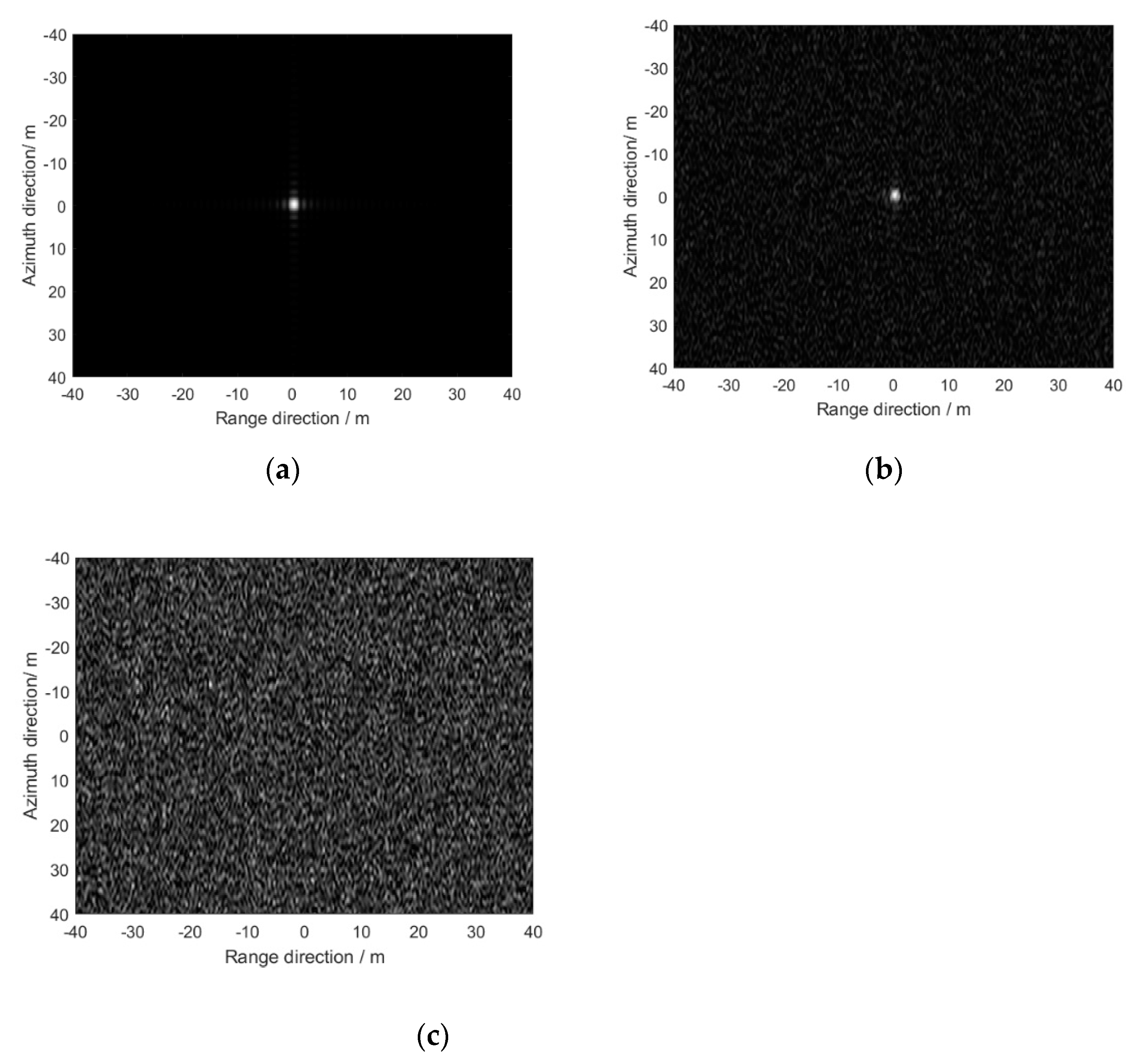
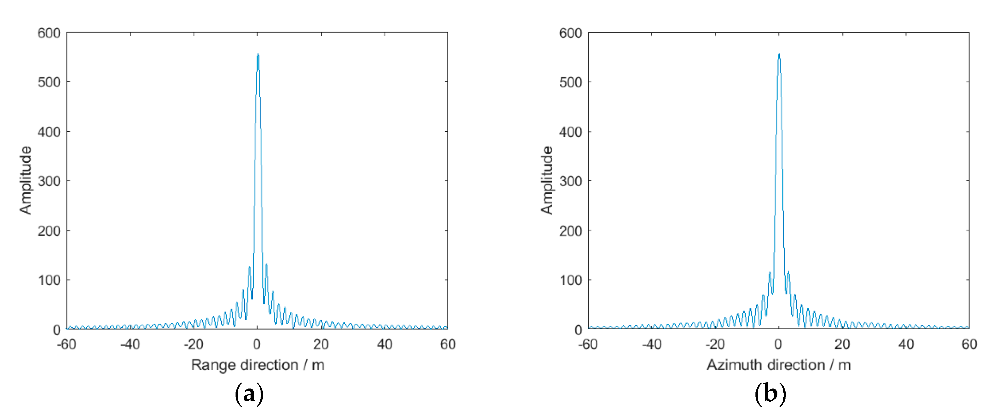
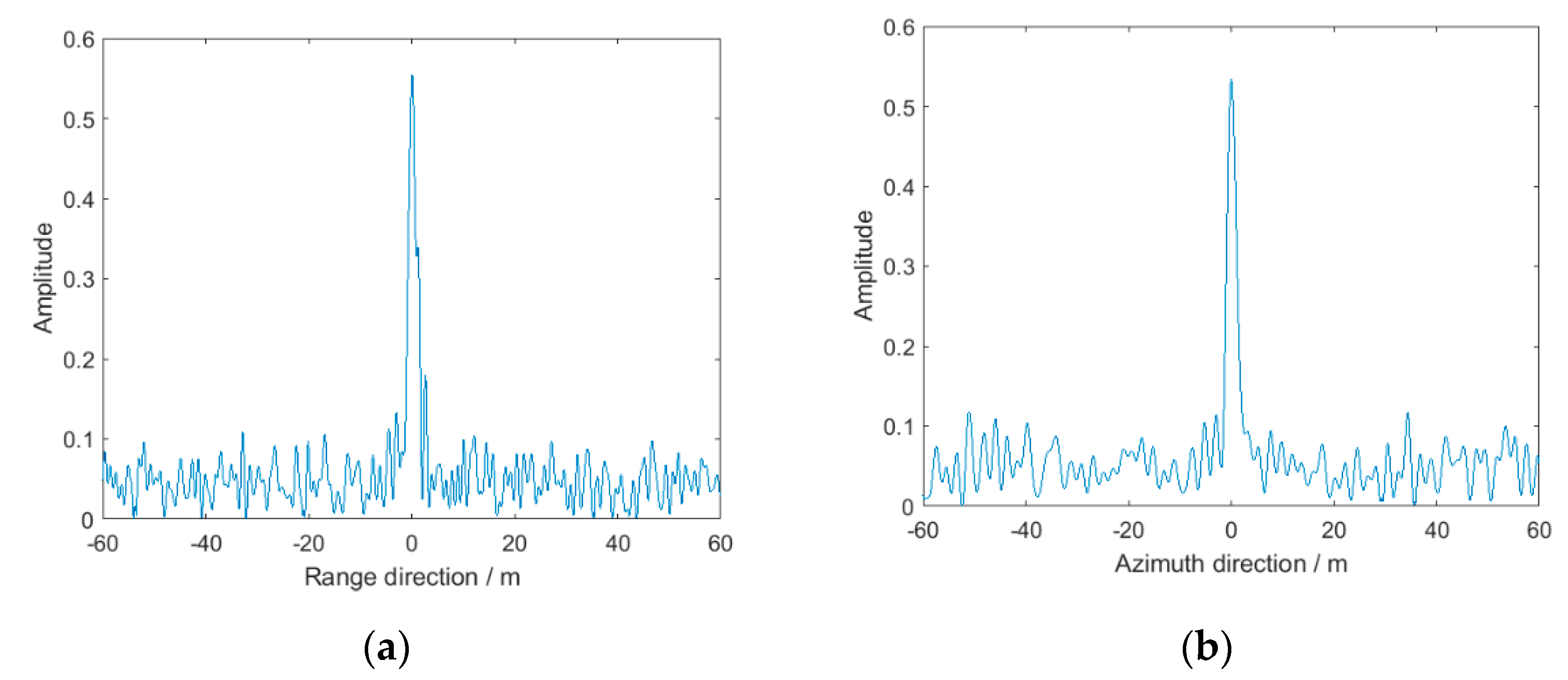
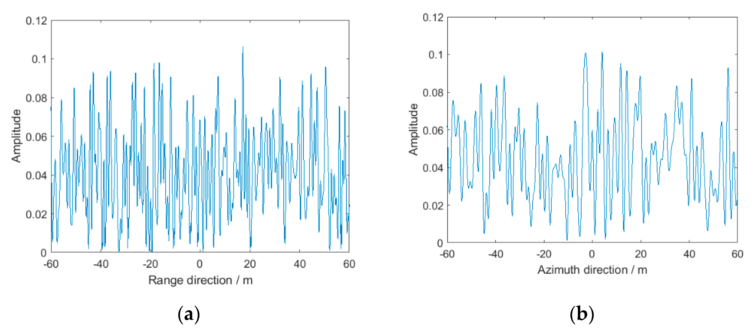
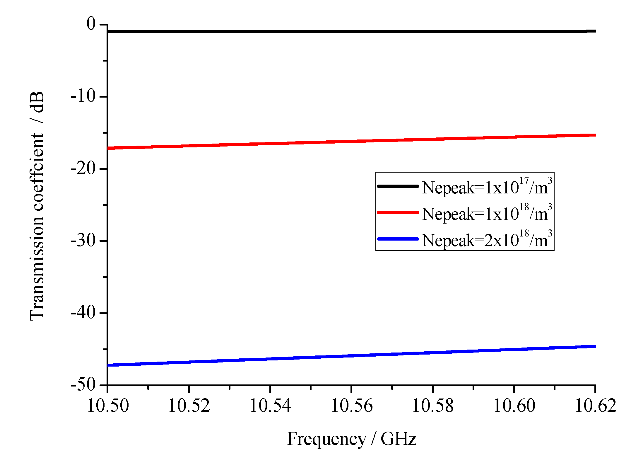
The simulation parameters of SAR and the plasma sheath are shown in Table 1. The point target imaging result under different electron density is shown in Figure 18, and corresponding range and azimuth compressed results are shown in Figure 19, Figure 20 and Figure 21. When the peak electron density of plasma sheath is 1 × 10¹⁷/m3, the plasma sheath has slight influence on the point target response shown in Figure 18a, and corresponding 1D results are not distorted by noise. However, when peak electron density increases to 1 × 10¹⁸/m3, the noise appears in the point target imaging result shown in Figure 18b, and amplitude of corresponding 1D results significantly decrease shown in Figure 20. Peak value of range and azimuth compressed result decrease and the energy of noise is close to the SAR signal energy, which lead to the abnormal main-lobe and side-lobe phenomenon. When the peak electron density of plasma sheath increases to the 2 × 10¹⁸/m3, the point target response result shown in Figure 18c is totally immersed in the noise, and the peak value cannot be distinguished from the noise. Due to significant attenuation, the energy of noise is far larger than the signal energy and this phenomenon occurs. For the further analysis, the transmission coefficients in bandwidth for Nepeak = 1 × 10¹⁷/m3, 1 × 10¹⁸/m3 and 2 × 10¹⁸/m3 are shown in Figure 22. For Nepeak = 1 × 10¹⁷/m3, the amplitude of transmission coefficient is around 0, which illustrates very small attenuation caused by plasma sheath. Therefore, the SNR of SAR signal with plasma sheath basically remains unchanged and SAR imaging quality is not influenced by plasma sheath. However, when the electron density is 1×10¹⁸/m3, the amplitude of transmission coefficient is around −16 dB, and SAR signal is serious attenuated. Compared with attenuated SAR signal, the energy of noise cannot be ignored. When the electron density is 2 × 10¹⁸/m3, the amplitude of transmission coefficient is around −46 dB and SAR signal is immersed in the noise, which will cause serious SAR image distortion. The result of transmission coefficient confirms the previous analysis.

3.2. Area Targets Response under Plasma Sheath

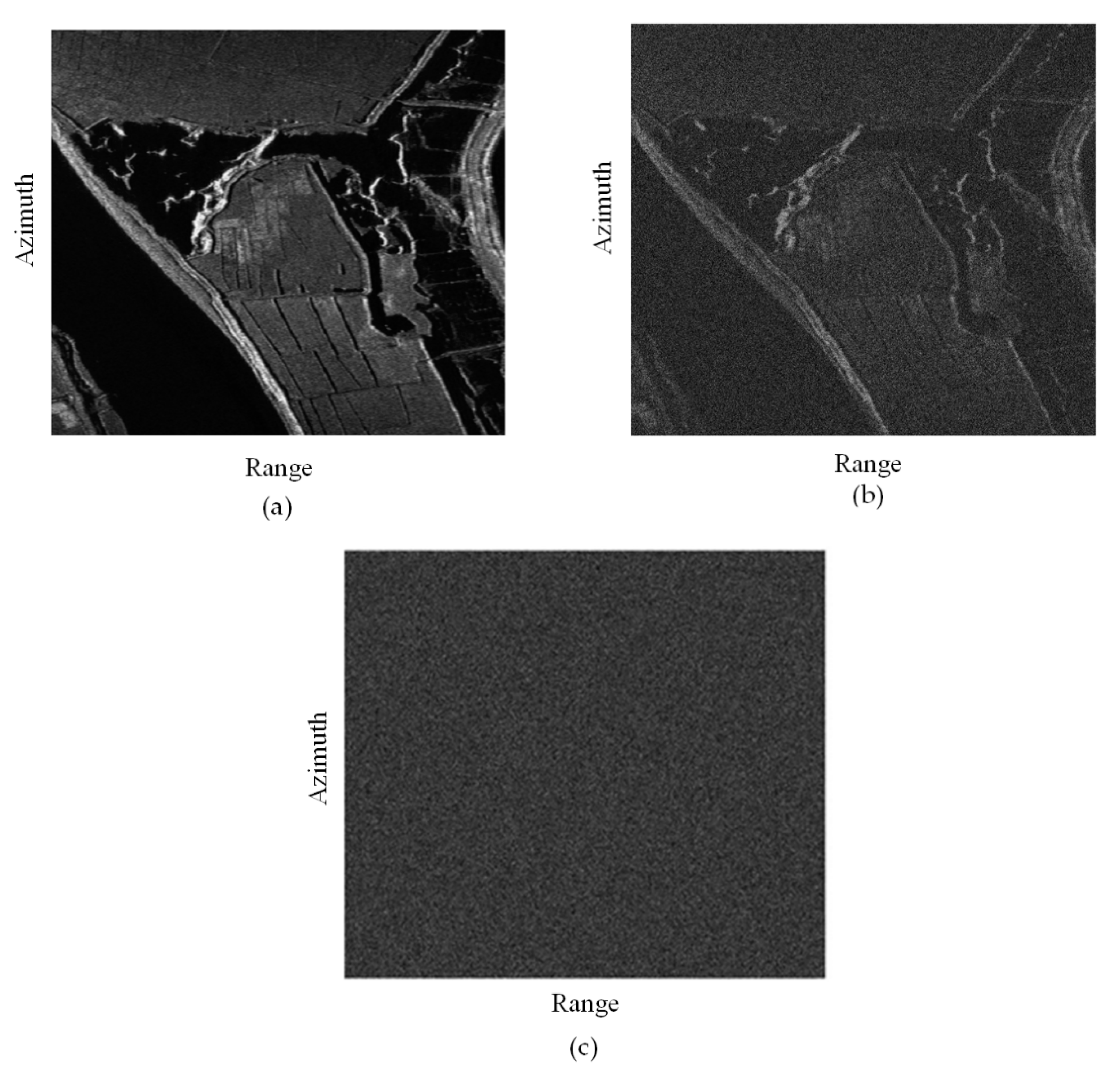
This section mainly demonstrates the plasma sheath effect on area targets. The simulation parameters are the same as Section 3.1. The real SAR image is used as the input radar-cross section information in echo generation. The signal to noise ratio (SNR) of the original SAR image is 15 dB. The distorted image caused by plasma sheath is shown in Figure 23.
From Figure 23a, it can be found that when the peak electron density of plasma sheath is 1 × 10¹⁷/m3, the real SAR image is hardly affected by the plasma sheath. Lakes, rivers, banks, and farmland are very clear. The quality of the image is good. However, as the peak electron density increases to 1 × 10¹⁸/m3, the imaging quality is severely degraded as shown in Figure 23b. The noise appears in the SAR image and lakes, rivers, banks, and farmland are not very clear. The imaging quality becomes worse compared with Figure 23a. When the peak electron density reaches 2 × 10¹⁸/m3, the imaging quality is the most serious shown in Figure 23c. All the lakes, rivers, banks, and farmland disappear, and only noise can be seen in the SAR image.

3.3. The Factors Determining SAR Imaging Quality

The previous analysis shows that peak electron density of plasma sheath plays an important role in SAR imaging under plasma sheath. Apart from the electron density, there are many critical factors determining the SAR imaging quality under plasma sheath, including carrier frequency and collision frequency. Therefore, how these parameters influence the SAR imaging quality should be clarified. The study of key factors determining SAR imaging quality will be beneficial to choose the appropriate flight condition to avoid the serious imaging quality degradation. In addition, the peak sidelobe ratio (PSLR) and integrated sidelobe ratio (ISLR) are two critical parameters to evaluate the SAR imaging quality, and the variation of PSLR and ISLR for target point imaging with different factors should be further investigated.
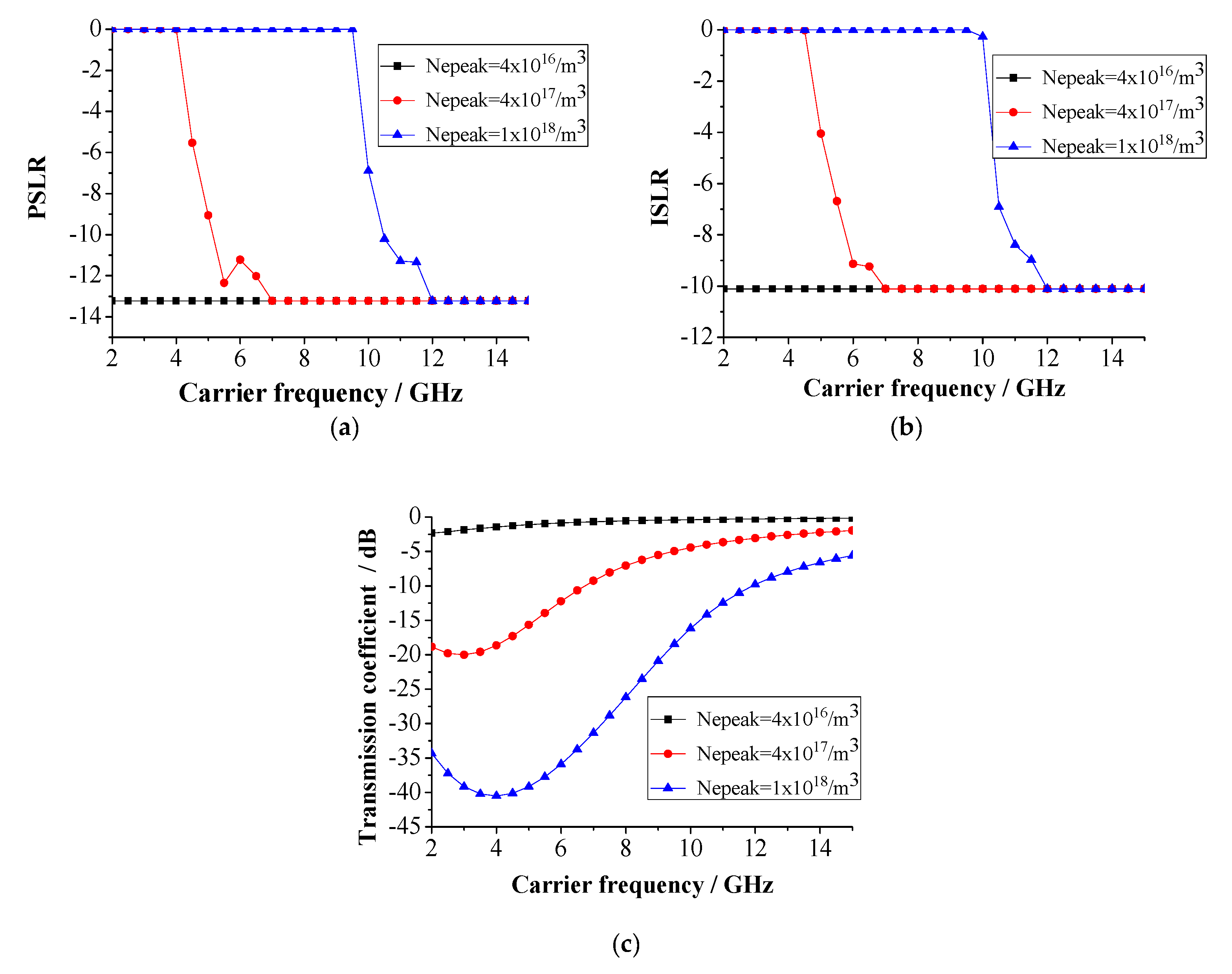
Firstly, the effects of carrier frequency and peak electron density on SAR imaging quality are explored. The carrier frequency varies from 2 to 15 GHz, and the peak values of electron density are 4 × 10¹⁶/m3, 4 × 10¹⁷/m3, and the 1 × 10¹⁸/m3, respectively. The other parameters are shown in Table 2. The PSLR and ISLR of range compressed result varying with carrier frequency and electron density are shown in Figure 24. The value 0 in Figure 24a,b means that there is no obvious peak, which is the same as the result in Figure 21. For Nepeak = 4 × 10¹⁶/m3 and Nepeak = 4 × 10¹⁷/m3 at low carrier frequency, the PSLR and ISLR are 0 which is due to significant attenuation shown in Figure 24c. The target response is immersed in the noise under this circumstance. With the increase of the carrier frequency, the value of PSLR gradually approaches −13.22 dB which is the ideal PSLR value. The value of ISLR approaches −10.11 dB which is also the ideal ISLR value. It can be concluded that the effect of plasma sheath on SAR imaging will weaken with the increase of carrier frequency. In addition, the PSLR at Nepeak = 4 × 10¹⁶/m3 is −13.22 dB for all carrier frequencies while the PSLR at Nepeak = 1 × 10¹⁸/m3 is 0 even when carrier frequency is 10 GHz which is a relatively large carrier frequency. We can also obtain that when the electron density is larger, the effect of plasma sheath on SAR imaging is more serious. This conclusion also confirms the result in Section 3.2.
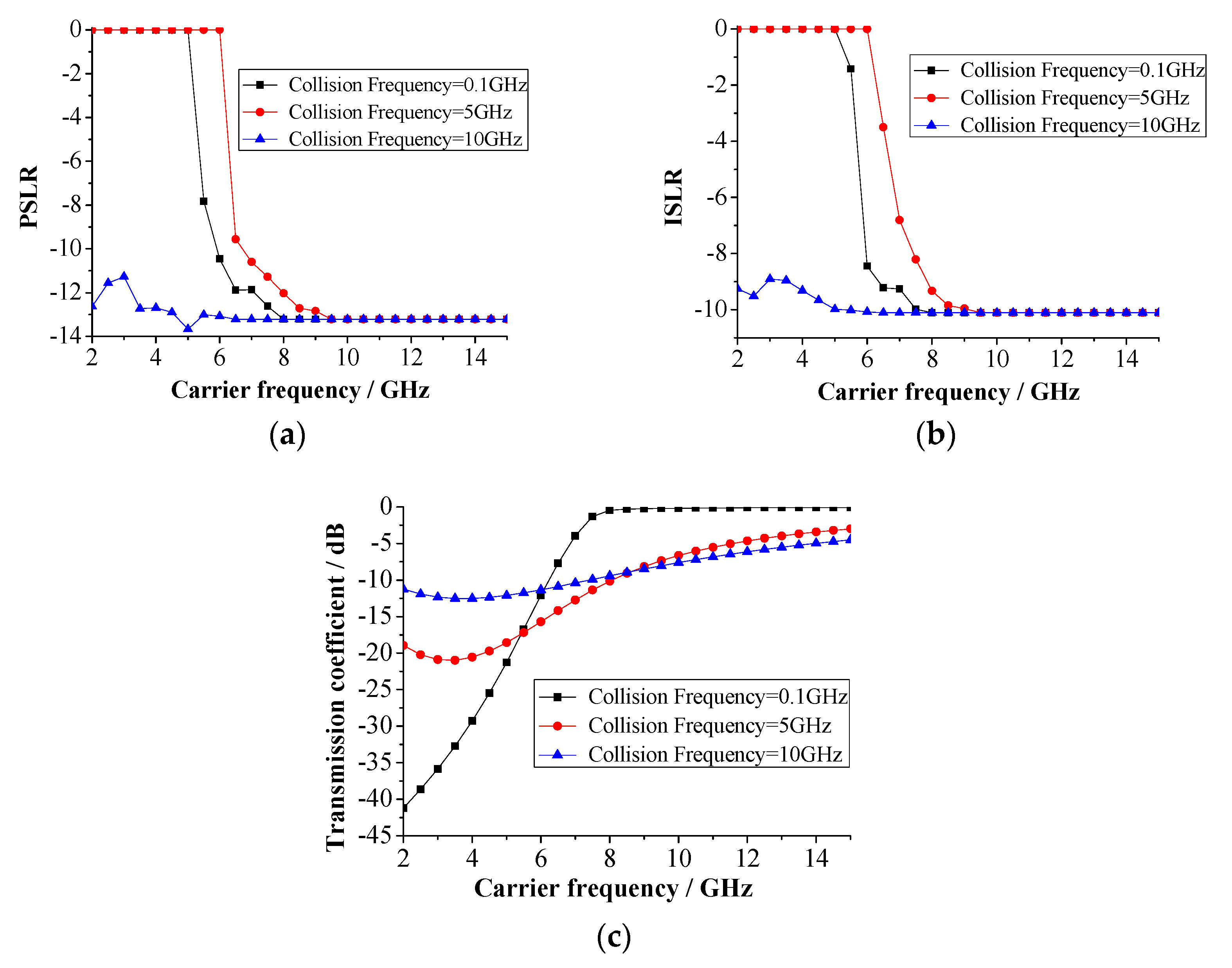
Moreover, the effect of collision frequency on hypersonic platform-borne SAR imaging is further studied and the results are shown in Figure 25. The simulation parameters are shown in Table 3. As shown in Figure 25, for collision frequency is 10 GHz, the PSLR and ISLR are around the ideal value. This is because the transmission coefficient at large collision frequency is relatively small. At small collision frequency, the PSLR and ISLR varies with carrier frequency significantly. This is due to the transmission coefficient curve varying with carrier frequency and the varying span of attenuation characteristics is large at small collision frequency condition.

4. Conclusions

The hypersonic platform-borne SAR imaging has promising application prospects, especially in the remote sensing area. However, the plasma sheath is a special phenomenon occurring during the hypersonic flight, which will bring new problems for hypersonic platform-borne SAR imaging. Therefore, in this paper, the hypersonic platform-borne SAR imaging under plasma sheath was studied from a physical perspective. The hypersonic platform-borne SAR signal model under plasma sheath was developed based on the SAR signal propagation characteristics in plasma sheath. The transmission coefficient was computed using scatter matrix method and characteristics of SAR signal doubly propagating through plasma sheath was coupled in the SAR signal model under plasma sheath. Secondly, SAR signal model under plasma sheath was verified experimentally. The ground experiment system was built and the SAR signal model under plasma sheath was verified by comparing the theoretical and experimental results of time domain, frequency domain, and range compressed signal. From the experiment result it can be found that not only the amplitude of signal waveform is attenuated but also the peak value of range compressed result decreases. Thirdly, the SAR imaging result under plasma sheath shows that point target and area targets response will be degraded by the attenuation caused by plasma sheath. When severe attenuation occurs, the response is even submerged in the noise. Finally, the effects of SAR and plasma sheath parameters including carrier frequency, electron density, and collision frequency on SAR imaging under plasma sheath are explored. It can be concluded that the severe degradation of SAR imaging quality appears at high plasma sheath electron density and low SAR carrier frequency condition. The SAR signal model under plasma sheath proposed in this paper will benefit the study of hypersonic platform-borne SAR imaging in the future. Moreover, the results in this paper provide a guidance for the design of hypersonic SAR imaging system to select the appropriate SAR and flight parameters to avoid the serious SAR imaging quality degradation.

Author Contributions

Conceptualization, L.S. and B.B.; model, L.S.; method, B.B.; experiment, L.S., X.L. and Y.L.; simulation, L.S., G.N.; investigation, L.S.; writing—original draft preparation, L.S.; writing—review and editing, B.B. and H.Z.; supervision, X.L.; funding acquisition, X.L and L.Z. All authors have read and agreed to the published version of the manuscript.

Funding

This work was supported in part by the National Natural Science Foundation of China under Grant 62001388, Grant 61701381, and Grant 61627901, in part by the Natural Science Basic Research Plan in Shaanxi Province of China under Grant 2020JM-102.

Data Availability Statement

Not applicable.

Acknowledgments

Not applicable.

Conflicts of Interest

The authors declare no conflict of interest.

References

  1. Tang, S.; Guo, P.; Zhang, L.; So, H.C. Focusing Hypersonic Vehicle-Borne SAR Data Using Radius/Angle Algorithm. IEEE Trans. Geosci. Remote Sens. 2019, 58, 281–293. [Google Scholar] [CrossRef]
  2. Xu, X.; Liao, G.; Yang, Z.; Wang, C. Moving-in-pulse duration model-based target integration method for HSV-borne high-resolution radar. Digit. Signal Process. 2017, 68, 31–43. [Google Scholar] [CrossRef]
  3. Han, J.; Cao, Y.; Yeo, T.S.; Wang, F. Robust Clutter Suppression and Ground Moving Target Imaging Method for a Multichannel SAR with High-Squint Angle Mounted on Hypersonic Vehicle. Remote Sens. 2021, 13, 2051. [Google Scholar] [CrossRef]
  4. Han, J.; Cao, Y.; Yeo, T.-S.; Wang, F.; Liu, S. A novel hypersonic vehicle-borne multichannel SAR-GMTI scheme based on adaptive sum and difference beams within eigenspace. Signal Process. 2021, 187, 108168. [Google Scholar] [CrossRef]
  5. Wang, Y.; Cao, Y.; Peng, Z.; Su, H. Clutter suppression and GMTI for hypersonic vehicle borne SAR system with MIMO antenna. IET Signal Process. 2017, 11, 909–915. [Google Scholar] [CrossRef]
  6. Stollery, J.L. Hypersonic flight. Nature 1972, 240, 133–135. [Google Scholar] [CrossRef]
  7. Starkey, R.P. Hypersonic Vehicle Telemetry Blackout Analysis. J. Spacecr. Rocket. 2015, 52, 426–438. [Google Scholar] [CrossRef]
  8. Chen, J.; Liang, B.; Yang, D.-G.; Zhao, D.-J.; Xing, M.; Sun, G.-C. Two-Step Accuracy Improvement of Motion Compensation for Airborne SAR with Ultrahigh Resolution and Wide Swath. IEEE Trans. Geosci. Remote Sens. 2019, 57, 7148–7160. [Google Scholar] [CrossRef]
  9. Jin, G.; Dong, Z.; He, F.; Yu, A. Background-Free Ground Moving Target Imaging for Multi-PRF Airborne SAR. IEEE Trans. Geosci. Remote Sens. 2019, 57, 1949–1962. [Google Scholar] [CrossRef]
  10. Wei, X.; Chong, J.; Zhao, Y.; Li, Y.; Yao, X. Airborne SAR Imaging Algorithm for Ocean Waves Based on Optimum Focus Setting. Remote Sens. 2019, 11, 564. [Google Scholar] [CrossRef] [Green Version]
  11. Ding, Z.; Xiao, F.; Xie, Y.; Yu, W.; Yang, Z.; Chen, L.; Long, T. A Modified Fixed-Point Chirp Scaling Algorithm Based on Updating Phase Factors Regionally for Spaceborne SAR Real-Time Imaging. IEEE Trans. Geosci. Remote Sens. 2018, 56, 7436–7451. [Google Scholar] [CrossRef]
  12. Tian, J.; Wu, Y.; Cai, Y.; Fan, H.; Yu, W. A Novel Mosaic Method for Spaceborne ScanSAR Images Based on Homography Matrix Compensation. Remote Sens. 2021, 13, 2866. [Google Scholar] [CrossRef]
  13. Wang, Y.; Li, J.; Yang, J.; Sun, B. A Novel Spaceborne Sliding Spotlight Range Sweep Synthetic Aperture Radar: System and Imaging. Remote Sens. 2017, 9, 783. [Google Scholar] [CrossRef] [Green Version]
  14. Chen, Z.; Zhou, Y.; Zhang, L.; Lin, C.; Huang, Y.; Tang, S. Ground Moving Target Imaging and Analysis for Near-Space Hypersonic Vehicle-Borne Synthetic Aperture Radar System with Squint Angle. Remote Sens. 2018, 10, 1966. [Google Scholar] [CrossRef] [Green Version]
  15. Wang, Y.; Cao, Y.; Wang, S.; Su, H. Clutter suppression and ground moving target imaging approach for hypersonic vehicle borne multichannel radar based on two-step focusing method. Digit. Signal Process. 2019, 85, 62–76. [Google Scholar] [CrossRef]
  16. Rybak, J.P.; Churchill, R.J. Progress in Reentry Communications. IEEE Trans. Aerosp. Electron. Syst. 1971, AES-7, 879–894. [Google Scholar] [CrossRef]
  17. Shao, C.; Nie, L.; Chen, W. Analysis of weakly ionized ablation plasma flows for a hypersonic vehicle. Aerosp. Sci. Technol. 2016, 51, 151–161. [Google Scholar] [CrossRef]
  18. Xie, K.; Yang, M.; Bai, B.; Li, X.; Zhou, H.; Guo, L. Re-entry communication through a plasma sheath using standing wave detection and adaptive data rate control. J. Appl. Phys. 2016, 119, 023301. [Google Scholar] [CrossRef]
  19. Li, L.; Wei, B.; Yang, Q.; Yang, X.; Ge, D. High-Order SO-DGTD Simulation of Radio Wave Propagation Through Inhomogeneous Weakly Ionized Dusty Plasma Sheath. IEEE Antennas Wirel. Propag. Lett. 2017, 16, 2078–2081. [Google Scholar] [CrossRef]
  20. Song, L.; Li, X.; Bai, B.; Liu, Y. Effects of Plasma Sheath on the Signal Detection of Narrowband Receiver. IEEE Trans. Plasma Sci. 2018, 47, 251–258. [Google Scholar] [CrossRef]
  21. Yao, B.; Li, X.; Shi, L.; Liu, Y.; Lei, F.; Zhu, C. Plasma sheath: An equivalent nonlinear mirror between electron density and transmitted electromagnetic signal. Phys. Plasmas 2017, 24, 102104. [Google Scholar] [CrossRef]
  22. Yao, B.; Li, X.; Shi, L.; Liu, Y.; Zhu, C. A Geometric-Stochastic Integrated Channel Model for Hypersonic Vehicle: A Physical Perspective. IEEE Trans. Veh. Technol. 2019, 68, 4328–4341. [Google Scholar] [CrossRef]
  23. Zhang, Y.; Liu, Y.; Li, X. A 2-D FDTD Model for Analysis of Plane Wave Propagation Through the Reentry Plasma Sheath. IEEE Trans. Antennas Propag. 2017, 65, 5940–5948. [Google Scholar] [CrossRef]
  24. Bai, B.; Li, X.; Liu, Y.; Xu, J.; Shi, L.; Xie, K. Effects of Reentry Plasma Sheath on the Polarization Properties of Obliquely Incident EM Waves. IEEE Trans. Plasma Sci. 2014, 42, 3365–3372. [Google Scholar] [CrossRef]
  25. Liu, Z.; Bao, W.; Li, X.; Liu, D.; Bai, B. Effects of Pressure Variation on Polarization Properties of Obliquely Incident RF Waves in Re-Entry Plasma Sheath. IEEE Trans. Plasma Sci. 2015, 43, 3147–3154. [Google Scholar] [CrossRef]
  26. Liu, H.; Liu, Y.; Yang, M.; Li, X. A Joint Demodulation and Estimation Algorithm for Plasma Sheath Channel: Extract Principal Curves with Deep Learning. IEEE Wirel. Commun. Lett. 2019, 9, 433–437. [Google Scholar] [CrossRef]
  27. Yang, M.; Li, X.; Wang, D.; Liu, Y.; He, P. Propagation of phase modulation signals in time-varying plasma. AIP Adv. 2016, 6, 055110. [Google Scholar] [CrossRef] [Green Version]
  28. Chen, X.-Y.; Li, K.-X.; Liu, Y.-Y.; Zhou, Y.-G.; Li, X.-P. Study of the influence of time-varying plasma sheath on radar echo signal. IEEE Trans. Plasma Sci. 2017, 45, 3166–3176. [Google Scholar] [CrossRef]
  29. Ding, Y.; Bai, B.; Gao, H.; Liu, Y.; Li, X.; Zhao, M. Method of Detecting a Target Enveloped by a Plasma Sheath Based on Doppler Frequency Compensation. IEEE Trans. Plasma Sci. 2020, 48, 4103–4111. [Google Scholar] [CrossRef]
  30. Bian, Z.; Li, J.; Guo, L. Simulation and Feature Extraction of the Dynamic Electromagnetic Scattering of a Hypersonic Vehicle Covered with Plasma Sheath. Remote Sens. 2020, 12, 2740. [Google Scholar] [CrossRef]
  31. Ren, Y.; Guo, L.; Chen, W.; Liu, S. Analysis of the electromagnetic scattering characteristics in two-dimensional time-varying and spatially non-uniform plasma sheath. Phys. Plasmas 2019, 24, 093515. [Google Scholar] [CrossRef]
  32. Sha, Y.-X.; Zhang, H.-L.; Guo, X.; Xia, M.-Y. Analyses of Electromagnetic Properties of a Hypersonic Object with Plasma Sheath. IEEE Trans. Antennas Propag. 2019, 67, 2470–2481. [Google Scholar] [CrossRef]
  33. Zheng, B.; Jiangting, L.; Lixin, G.; Xi, L. Range Profile Analysis of Hypersonic Vehicles Covered by Inhomogeneous Plasma Sheath Using Physical Optics. IEEE Trans. Plasma Sci. 2019, 47, 4961–4970. [Google Scholar] [CrossRef]
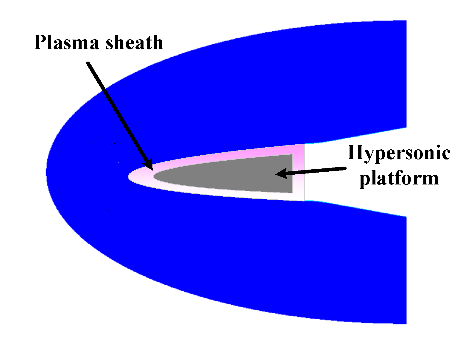
Figure 1. The hypersonic platform covered by plasma sheath.
Remotesensing 13 04943 g001
Figure 2. The flow field simulation result.
Remotesensing 13 04943 g002
Figure 3. The plasma sheath near the antenna.
Remotesensing 13 04943 g003
Figure 4. Mean profile of electron density outward from the platform surface.
Remotesensing 13 04943 g004
Figure 5. The wave propagation in multi-layer plasma sheath.
Remotesensing 13 04943 g005
Figure 6. Outline of plasma generator used in experiment. (a) Photo of plasma generator. (b) Schematic diagram of plasma generator.
Remotesensing 13 04943 g006
Figure 7. The plasma produced in the experiment.
Remotesensing 13 04943 g007
Figure 8. Overview of experimental equipment configuration.
Remotesensing 13 04943 g008
Figure 9. Schematic diagram of SAR signal passing through plasma sheath.
Remotesensing 13 04943 g009
Figure 10. The signal in time domain without plasma sheath: (a) experimental result, (b) theoretical result.
Remotesensing 13 04943 g010
Figure 11. Signal frequency spectrum without plasma sheath: (a) experimental result, (b) theoretical result.
Remotesensing 13 04943 g011
Figure 12. Range compressed signal without plasma sheath: (a) experimental result, (b) theoretical result.
Remotesensing 13 04943 g012
Figure 13. Signal with plasma sheath: (a) experimental result, (b) theoretical result.
Remotesensing 13 04943 g013
Figure 14. Signal frequency spectrum with plasma sheath: (a) experimental result, (b) theoretical result.
Remotesensing 13 04943 g014
Figure 15. Range compressed result with plasma sheath: (a) experimental result, (b) theoretical result.
Remotesensing 13 04943 g015
Figure 16. Transmission coefficient for SAR signal in bandwidth.
Remotesensing 13 04943 g016
Figure 17. Signal phase shift characteristics caused by plasma within signal bandwidth: (a) theoretical result, (b) experimental result.
Remotesensing 13 04943 g017
Figure 18. Point target imaging result with plasma sheath. (a) Nepeak = 1 × 10¹⁷/m3, (b) Nepeak = 1 × 10¹⁸/m3, (c) Nepeak = 2 × 10¹⁸/m3.
Remotesensing 13 04943 g018
Figure 19. 1D result when Nepeak = 1 × 10¹⁷/m3: (a) range dimension, (b) azimuth dimension.
Remotesensing 13 04943 g019
Figure 20. 1D result when Nepeak = 1 × 10¹⁸/m3: (a) range dimension, (b) azimuth dimension.
Remotesensing 13 04943 g020
Figure 21. 1D result when Nepeak = 2 × 10¹⁸/m3: (a) range dimension, (b) azimuth dimension.
Remotesensing 13 04943 g021
Figure 22. Transmission coefficient for different peak electron density.
Remotesensing 13 04943 g022
Figure 23. Area targets response: (a) Nepeak = 1 × 10¹⁷/m3, (b) Nepeak = 1 × 10¹⁸/m3, (c) Nepeak = 2 × 10¹⁸/m3.
Remotesensing 13 04943 g023
Figure 24. (a) PSLR varying with carrier frequency and electron density. (b) ISLR varying with carrier frequency and electron density. (c) Transmission coefficient varying with carrier frequency and electron density.
Remotesensing 13 04943 g024
Figure 25. (a) PSLR varying with collision frequency and carrier frequency. (b) ISLR varying with collision frequency and carrier frequency. (c) Transmission coefficient varying with collision frequency and carrier frequency.
Remotesensing 13 04943 g025
Table 1. Simulation parameters.
ParametersValue
Pulse width40 μs
Bandwidth120 MHz
Carrier frequency10.5 GHz
PRF7460 Hz
Platform velocity7000 m/s
Elevation angle35°
Collision frequency4 GHz
SNR15 dB
Table 2. Simulation parameters.
ParametersValue
Pulse width40 μs
Bandwidth120 MHz
PRF7460 Hz
Platform velocity7000 m/s
Elevation angle30°
Collision frequency4 GHz
SNR10 dB
Table 3. Simulation parameters.
ParametersValue
Pulse width40 μs
Bandwidth120 MHz
PRF7460 Hz
Platform velocity7000 m/s
Elevation angle30°
Peak electron density5 × 1017/m3
SNR10 dB
Publisher’s Note: MDPI stays neutral with regard to jurisdictional claims in published maps and institutional affiliations.