Next Article in Journal
A Novel Method for Layover Detection in Mountainous Areas with SAR Images
Previous Article in Journal
Study on Urban Spatial Pattern Based on DMSP/OLS and NPP/VIIRS in Democratic People’s Republic of Korea
 
 
Correction published on 26 December 2022, see Remote Sens. 2023, 15(1), 116.
Technical Note

A New Triangulation Algorithm for Positioning Space Debris

1
Changchun Observatory of National Astronomical Observatory, Chinese Academy of Sciences, Changchun 130117, China
2
School of Astronomy and Space Science, University of Chinese Academy of Sciences, Beijing 100049, China
*
Author to whom correspondence should be addressed.
Remote Sens. 2021, 13(23), 4878; https://doi.org/10.3390/rs13234878
Submission received: 2 November 2021 / Revised: 26 November 2021 / Accepted: 28 November 2021 / Published: 1 December 2021 / Corrected: 26 December 2022

Abstract

:
A single electro-optical (EO) sensor used in space debris observation provides angle-only information. However, space debris position can be derived using simultaneous optical measurements obtained from two EO sensors located at two separate observation sites, and this is commonly known as triangulation. In this paper, we propose a new triangulation algorithm to determine space debris position, and its analytical expression of Root-Mean-Square (RMS) position error is presented. The simulation of two-site observation is conducted to compare the RMS positioning error of the proposed triangulation algorithm with traditional triangulation algorithms. The results show that the maximum RMS position error of the proposed triangulation algorithm is not more than 200 m, the proposed triangulation algorithm has higher positioning accuracy than traditional triangulation algorithms, and the RMS position error obtained in the simulation is nearly consistent with the analytical expression of RMS position error. In addition, initial orbit determination (IOD) is carried out by using the triangulation positioning data, and the results show that the IOD accuracy of two-site observation is significantly higher than that of the single-site observation.

Graphical Abstract

1. Introduction

Space debris is defunct artificial objects in space, and it began to accumulate in Earth’s orbit immediately with the first launch of an artificial satellite, Sputnik 1, into orbit in October 1957. As of August 2021, more than 900,000 pieces of debris larger than 1 cm are estimated to be in orbit around the Earth [1]. According to some computer models, the amount of space debris has reached a tipping point, with enough currently in orbit to continually collide and create even more debris, raising the risk of spacecraft failures [2,3]. Due to the potential threat that space debris poses, space debris observation and orbit determination are increasingly needed.
Optical observation is now widely used in space debris observation because it is unrestricted by the distance to observation objects and is cost-efficient compared to radar, and several countries and organizations have carried out optical space debris observation [4,5,6,7,8,9,10,11,12,13,14,15,16]. Electro-optical (EO) sensors are the primary instrument for optical observation systems. Optical observation systems use EO sensors to collect images of space debris and extract angle information from the collected images [17]. Optical observation does not intrinsically provide range information, and therefore we cannot directly obtain space debris position by a single EO sensor; however, space debris position can be derived using simultaneous optical measurements obtained from two EO sensors located at two separate observation sites, and this is commonly known as triangulation [18,19]. Yanagisawa et al. propose a ground-based optical observation system for monitoring and positioning low earth orbit (LEO) objects, which consists of two arrays of EO sensors located at two longitudinally separate observation sites [20]. In the absence of observation error, the triangulation problem is trivial; however, when observation error is present, the line-of-sight (LOS) of two sensors will not generally meet, in which case it is necessary to find the best point of intersection as the most probable space debris position. There are several algorithms to solve this problem. For example, a commonly suggested algorithm [21] takes the midpoint of the shortest line between two lines of sight as the most probable space debris position; in [22], the most probable space debris position is taken as a point on the shortest line between two lines of sight, which subtend equal residual angles at sites. Obtaining the positioning errors in the triangulation solution is a complicated problem, and numerical solutions are usually sought, but it is difficult to fully reflect the nature of the dependence between errors and experimental parameters involved in numerical studies. In [23], the analytical expression for the Root-Mean-Square (RMS) position error of triangulation is presented.
Triangulation has many applications, and one is to improve the accuracy of short-arc angles-only initial orbit determination. Initial orbit determination (IOD) refers to determining the orbit of the space objects using observation data, which is the key to space debris cataloging. Affected by the relative velocity between space debris and the EO sensors, the observed arcs are generally too short, especially for ground-based observation of LEO space debris or space-based observation [24,25]. Since the observed arcs are too short and lack range information, the short-arc angles-only initial orbit determination results generally have large errors [26]. However, based on triangulation using two EO sensors, the angles-only IOD problem is converted to the IOD using 3D position data, and the IOD accuracy can be significantly improved.
To obtain better positioning results, it is desirable to find a triangulation algorithm that improves positioning results by introducing observation accuracy parameters. This paper addresses this problem by assuming that the space debris state observed by EO sensors is subject to Gaussian distribution, and derives the space debris position by the statistics method. In addition, the analytical expression for the RMS position error of the proposed triangulation algorithm is presented. In a series of simulations, the algorithm is extensively tested against other triangulation algorithms. The rest of this paper is organized as follows: in Section 2, a new triangulation algorithm is proposed, and its analytical expression of RMS position errors is presented. In Section 3, the simulation of two-site observation is conducted to compare the RMS positioning error of the proposed triangulation algorithm with traditional triangulation algorithms, and the results and discussion are presented in Section 4 and Section 5, respectively. Finally, the conclusions are given in Section 6.

2. Methods

2.1. Triangulation Algorithm

In Figure 1, the two EO sensors located at two arbitrary observation sites are denoted by A and B, respectively. The LOS vectors from the EO sensors to space debris are denoted by L A and L B , respectively, and the line segment MN is the common perpendicular of them. Figure 2 illustrates the right ascension and declination (RADEC) of a LOS vector in the topocentric coordinate systems. With RADEC measurements, it is possible to calculate the LOS vector:
L i = [ cos δ i cos α i cos δ i sin α i sin δ i ] ,
The object in triangulation is to derive the space debris position X T from the space debris state X θ observed by two EO sensors. We address this problem by assuming that the space debris state observed by EO sensors is subject to Gaussian distribution, with mean value X θ ¯ = [ α A , δ A , α B , δ B ] , which are RADEC measurements of EO sensors, and variance σ θ 2 = [ σ α A 2 , σ δ A 2 , σ α B 2 , σ δ B 2 ] , which is the uncertainty of RADEC measurements, and it can be assumed that RMS errors σ α A , σ δ A , σ α B and σ δ B are uncorrelated. According to the traditional triangulation algorithms, it is generally believed that the actual space debris position is near the line segment MN, and therefore it can be assumed that the position of point M is the mean value of the space debris position determined by the EO sensor A with the assistance of EO sensor B. Similarly, the position of point N is regarded as the mean value of the space debris position determined by EO sensor B with the assistance of EO sensor A.
To determine the space debris position, the positions of points M and N and their variances need to be calculated. From Figure 1, according to the triangle law of vector addition, in geocentric coordinate systems, the expressions for X M and X N with respect to LOS vectors L A and L B are given by:
X M = X A + ρ M L A ,
X N = X B + ρ N L B ,
where L A and L B can be calculated by Equation (1); X A = [ x A y A z A ] T and X B = [ x B y B z B ] T are the positions of two observation sites where the two EO sensors are located; ρ M is the range from sensor A to point M; and ρ N is the range from sensor B to point N. Except for ρ M and ρ N , all the ingredients for deriving the expressions of X M and X N are now known, and they can be calculated by analytic geometry. Since line segment MN is the common perpendicular of L A and L B , we can obtain equation:
M N L A = M N L B = 0 ,
Substituting Equations (2) and (3) into Equation (4) yields:
{ L A ( X A X B ) + ρ M ρ N L A L B = 0 L B ( X A X B ) + ρ M ρ N L A L B = 0 ,
Solving Equation (5) and after further simplification, we obtain:
ρ M = L A A B + ( L A L B ) ( L B A B ) ( L A L B ) 2 1 ,
ρ N = L B A B + ( L A L B ) ( L A A B ) ( L A L B ) 2 1 ,
where A B = X B X A . Then, substituting Equations (6) and (7) into Equations (2) and (3), respectively, we obtain the expressions for X M and X N , respectively:
X M = X A + L A A B + ( L A L B ) ( L B A B ) ( L A L B ) 2 1 L A ,
X N = X B + L B A B + ( L A L B ) ( L A A B ) ( L A L B ) 2 1 L B .
Using Equation (1), Equations (8) and (9) can be further simplified to give the expressions for X M and X N with respect to variables α A , δ A , α B , and δ B , respectively.
According to the law of propagation error, the covariance matrix of point M can be calculated:
P M = J M P A J M T ,
where J M = [ x M α A y M α A z M α A x M δ A y M δ A z M δ A x M α B y M α B z M α B x M δ B y M δ B z M δ B ] , and P A = [ σ α A 2 0 0 0 0 σ δ A 2 0 0 0 0 σ α A 2 0 0 0 0 σ δ A 2 ] .
Similarly, the covariance matrix of point N can be calculated:
P N = J N P B J N T ,
where J N = [ x N α A y N α A z N α A x N δ A y N δ A z N δ A x N α B y N α B z N α B x N δ B y N δ B z N δ B ] , and P B = [ σ α B 2 0 0 0 0 σ δ B 2 0 0 0 0 σ α B 2 0 0 0 0 σ δ B 2 ] .
We now have two Gaussian distributions—the position of point M is subject to Gaussian distribution:
p M ( X ) = 1 ( 2 π ) 3 2 | P M | 1 2 e ( X X M ) T P M 1 ( X X M ) 2 ,
and the position of point N is subject to Gaussian distribution:
p N ( X ) = 1 ( 2 π ) 3 2 | P N | 1 2 e ( X X N ) T P N 1 ( X X N ) 2 ,
Both of them are the actual position estimates of space debris, and our goal is to obtain a new distribution that is the configuration for which both estimates are most likely, and the mean of the new distribution is the most probable space debris position given all the information we have. According to Bayes’ theorem, the new distribution is given by:
p ( X ) = p M ( X ) p N ( X ) = 1 ( 2 π ) 3 2 | P T | 1 2 e ( X X T ) T P T 1 ( X X T ) 2 ,
The new distribution is also a Gaussian distribution, and its mean value and variance are given by:
X T = ( P M 1 + P N 1 ) 1 ( P M 1 X M + P N 1 X N ) ,
P T = ( P M 1 + P N 1 ) 1 ,
where X T is the most probable space debris position obtained by using the proposed triangulation algorithm. The summary of the above triangulation algorithm (Algorithm 1) is listed below.
Algorithm 1. Summary of the proposed triangulation algorithm
Input: The two EO sensor positions X A and X A ; The two EO sensors’ observation RMS errors σ α A , σ δ A , σ α B and σ δ B ; The simultaneous optical measurements X θ ¯ .
Output: Space debris position X T .
 1: Compute X M and X N from Equations (8) and (9).
 2: Compute P M and P N from Equations (10) and (11).
 1: Compute X T from Equation (15).

2.2. Positioning Error

According to previous studies, the positioning error of triangulation is not only related to the observation error of EO sensors but also depends on the configuration between the LOS vectors and the baseline of two EO sensors. In order to analyze the RMS position error of the proposed triangulation algorithm, we rewrite Equation (15) as:
X T = K X M + ( I K ) X N ,
where K = P M 1 ( P M 1 + P N 1 ) 1 is a weighting matrix and I is an identity matrix, and then the space debris position error is given by:
R ¯ = K R M ¯ r M + ( I K ) R N ¯ r N ,
where R M and R N are the position errors of points M and N, respectively, and the vectors r M and r N are their direction vectors. In order to obtain the expressions of RMS position error, we have to derive the expressions of R M and R N .
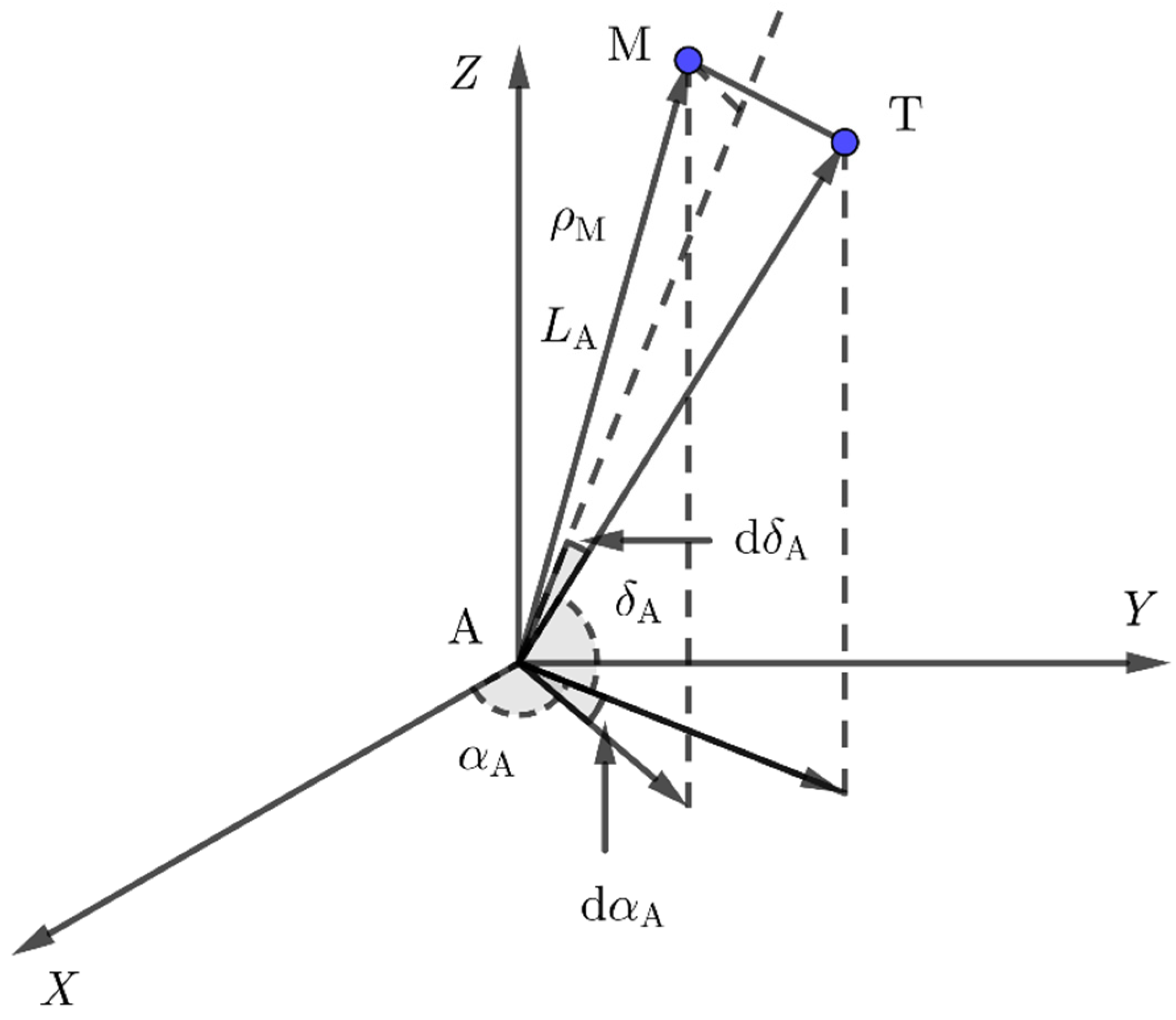
From Figure 3, the two EO sensors located at two arbitrary observation sites are denoted by A and B, respectively. The actual position of space debris is denoted by T. d α A and d φ A are the LOS vector errors in the topocentric coordinate systems. Similarly, d α B , d φ B are the LOS vector errors in the topocentric coordinate systems. Since d α A , d φ A are small, by Equation (6), the RMS position error of point M in triangulation is given by:
R M ¯ = ρ M ( d α A 2 ¯ + d δ A 2 ¯ ) 1 2 = L A A B + ( L A L B ) ( L B A B ) ( L A L B ) 2 1 ( σ α A 2 + σ δ A 2 ) 1 2 ,
Similarly, with Equation (7), the RMS position error of point N in triangulation is given by:
R N ¯ = ρ N ( d α B 2 ¯ + d δ B 2 ¯ ) 1 2 = L B A B + ( L A L B ) ( L A A B ) ( L A L B ) 2 1 ( σ α B 2 + σ δ B 2 ) 1 2 ,
Substituting Equations (19) and (20) into Equation (18) yields:
R ¯ = K L A A B + ( L A L B ) ( L B A B ) ( L A L B ) 2 1 ( σ α A 2 + σ δ A 2 ) 1 2 r M + ( I K ) L B A B + ( L A L B ) ( L A A B ) ( L A L B ) 2 1 ( σ α B 2 + σ δ B 2 ) 1 2 r N ,
Since it is impossible to know the actual space debris position, the vectors r M and r N cannot be solved. However, we can approximately think vector r N is equal to vector r MN , which is the unit vector of M N , because the actual space debris position is near the line segment MN. Similarly, the vector r M is equal to vector r MN , approximately. Therefore, Equation (30) can be rewritten as:
R ¯ = ( I K ) L B A B + ( L A L B ) ( L A A B ) ( L A L B ) 2 1 ( σ α B 2 + σ δ B 2 ) 1 2 r MN K L A A B + ( L A L B ) ( L B A B ) ( L A L B ) 2 1 ( σ α A 2 + σ δ A 2 ) 1 2 r MN ,
where r MN = L A × L B because the line segment MN is the common perpendicular of L A and L B .

3. Simulation Procedure

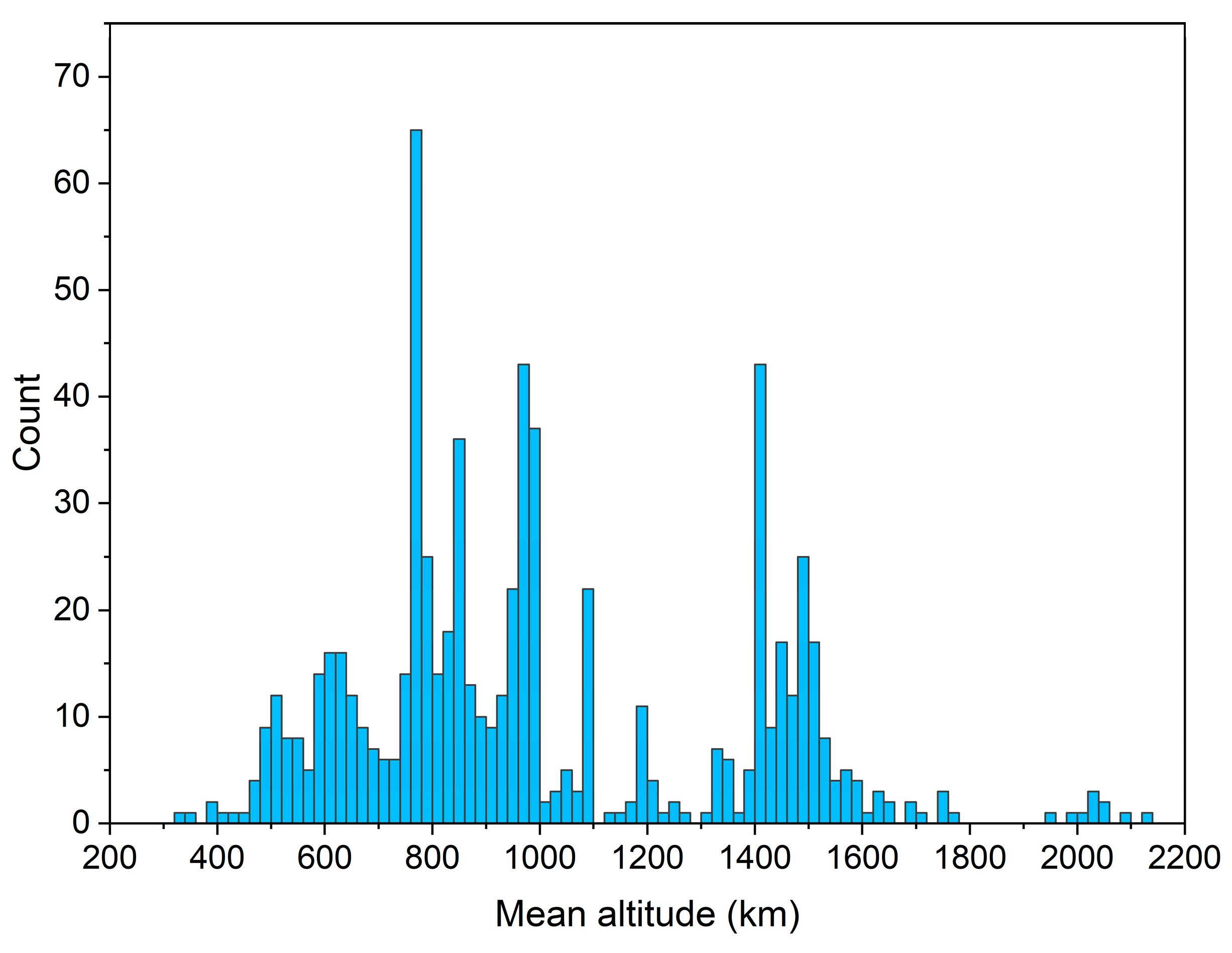
This section introduces the simulation procedure of space debris observation by triangulation. The purposes of this simulation are, on one hand, to compare the RMS positioning error of the proposed triangulation algorithm with traditional triangulation algorithms, and on the other hand, to evaluate the IOD errors using triangulation positioning data. Based on optical measurements from Jilin Space Tracking Base of Changchun Observatory, China, a ground-based simulation is conducted from Jan. 13, 2020, to Feb. 8, 2020. A total of 702 pieces of TLE-cataloged LEO space debris in the near-circular path are selected as the reference population, and the mean altitude distribution of these space debris is shown in Figure 4. The triangulation for positioning LEO space debris has the minimum error when the baseline between two EO sensors is about 1600 km [27]. Therefore, we choose the Changchun Observatory, China, and the Sheshan Observatory in Shanghai, China as the simulated observation sites where the EO sensors are set (the baseline between them is 1456.36 km). The simulation procedure is organized as follows:
  • Based on optical measurements from Jilin Space Tracking Base of Changchun Observatory, precise orbit determination (POD) is performed on the selected LEO space debris to obtain their precise ephemeris;
  • Based on the ephemeris obtained in step 1, the simultaneous observation arc consists of a series of consecutive simultaneous RADEC pseudo-measurements generated for the two simulation observation sites, and each RADEC pseudo-measurement is corrupted with Gaussian noise of 9″. The length and sampling interval of the simultaneous observation arc are set at 30 s and 1 s, respectively. In addition, the detection constraints are also considered in the simulation, including the visibility of space debris to the observation sites, but not the EO sensors’ performance and weather conditions;
  • Based on the simultaneous RADEC pseudo-measurements obtained in step 2, the space debris position can be calculated by the proposed triangulation algorithm and two traditional triangulation algorithms, respectively. The positioning results are compared with the ephemeris, and the RMS position errors of the above three triangulation algorithms are evaluated;
  • The initial orbit of selected LEO space debris is calculated using the obtained positioning results in step 3, the initial orbit results are compared with the reference orbit obtained in step 1, and IOD errors are evaluated. Due to the length of the detection arc, the Herrick–Gibbs method and differential correction are used in IOD processes [28].

4. Results

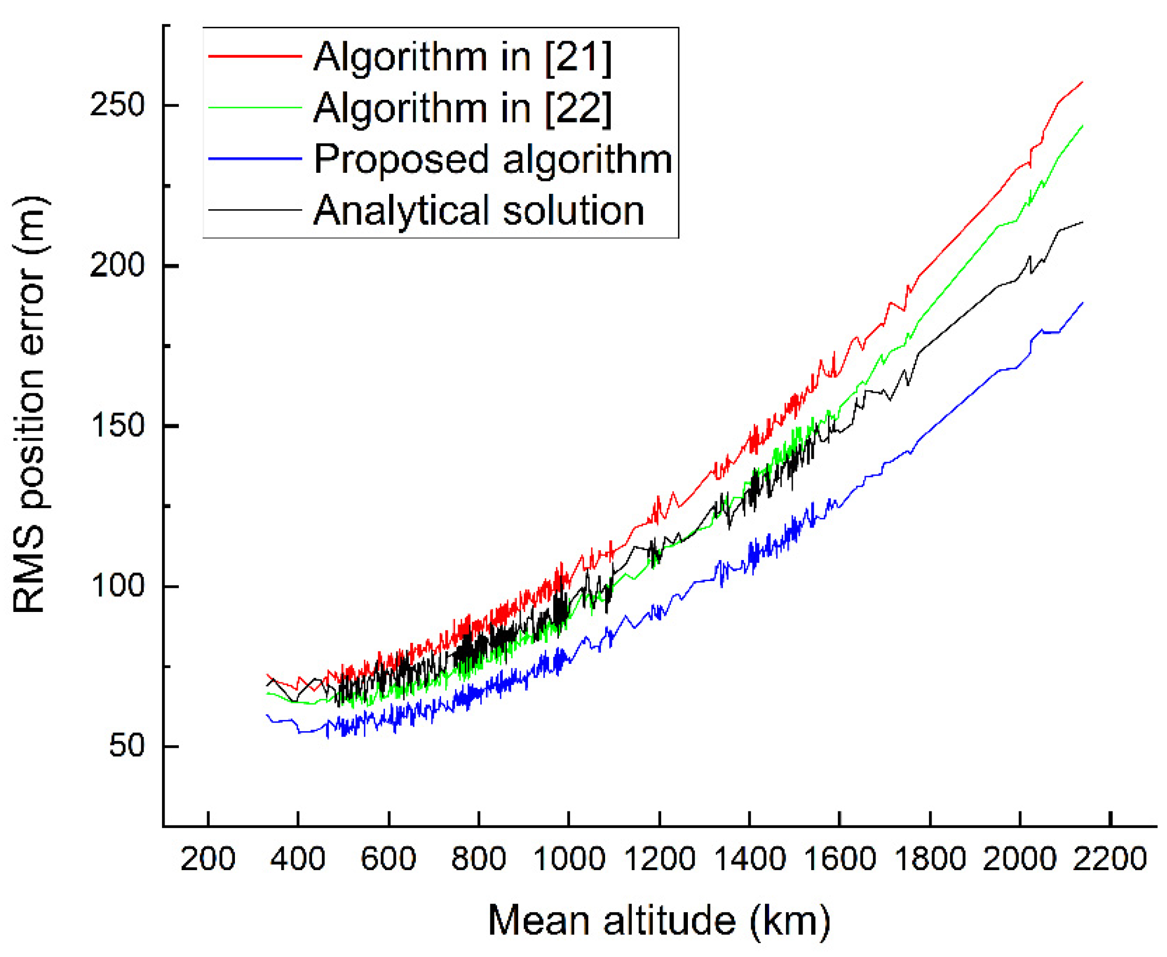
In this section, the results for the RMS position error and IOD error of space debris described above in Section 3 are presented. In the 27-day simulation period, we obtained a total of 18,954 simultaneous observation arcs of the 702 pieces of TLE-cataloged LEO space debris, and each space object has more than 20 simultaneous observation arcs. Figure 5 shows the RMS position error using the proposed triangulation algorithm and two traditional triangulation algorithms, respectively. The RMS position error refers to the Root-Mean-Square position error of all sampling points on the simultaneous observation arcs. In addition, the analytical RMS position error calculated by Equation (32) is also plotted in Figure 5.
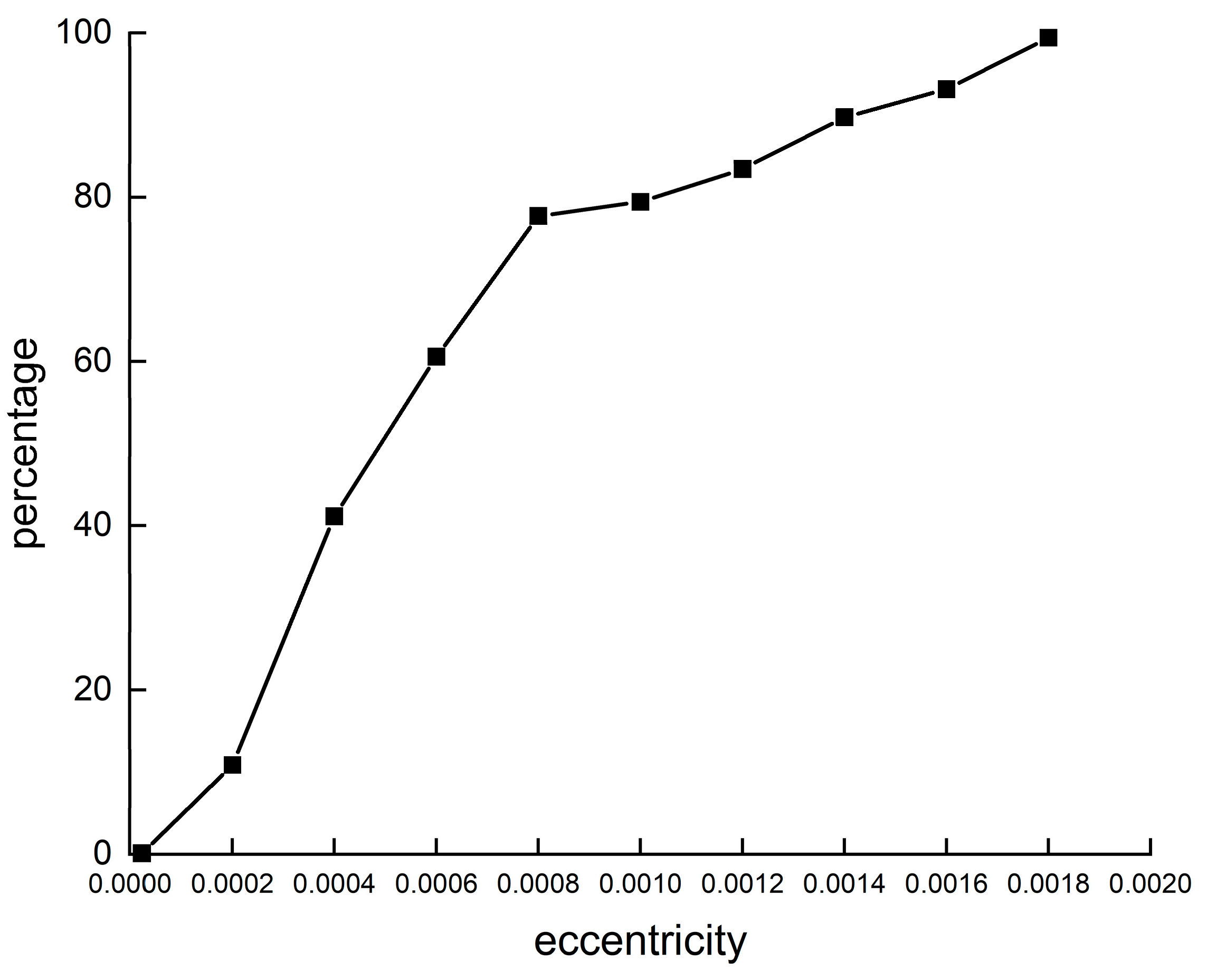
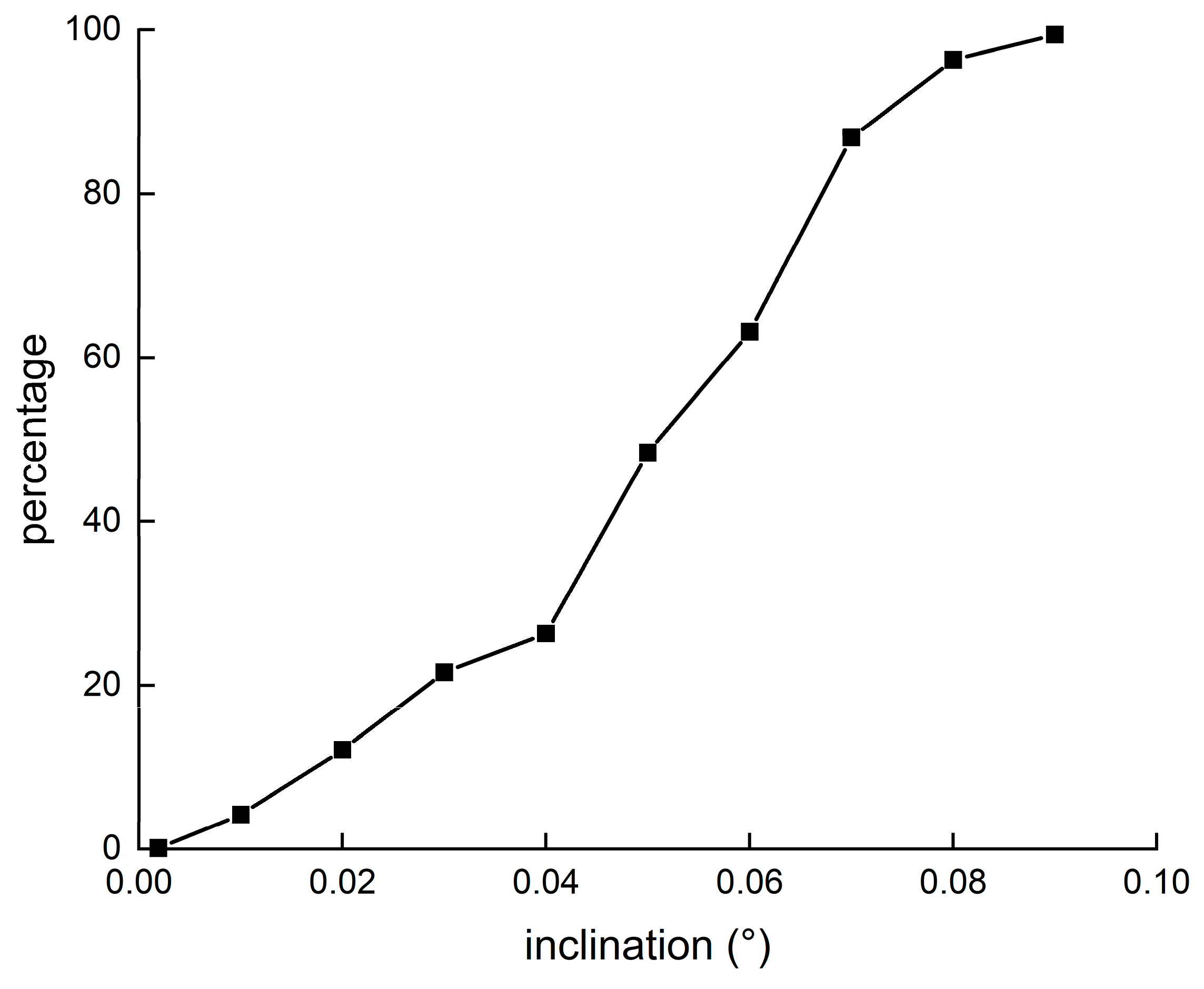
IOD is carried out by using the triangulation positioning data obtained in step 3. We calculate the total of 18954 IOD cases for 702 pieces of TLE-cataloged LEO space debris, and compare the results with the reference orbit obtained in step 1. Figure 6, Figure 7 and Figure 8 show the IOD error, and we use orbit elements’ semi-major axis (SMA), eccentricity, and inclination to characterize IOD errors.

5. Discussion

For LEO space debris in the simulation, Figure 5 shows that the maximum RMS position error of two traditional triangulation algorithms exceeds 250 m; however, the maximum RMS position error of the proposed triangulation algorithm is not more than 200 m. It is obvious that the RMS position errors of the proposed triangulation algorithm are better than those of the other two traditional triangulation algorithms. Therefore, the introduction of observation accuracy parameters into the triangulation algorithm can effectively improve the positioning accuracy. For the proposed triangulation algorithm, the RMS position error of the numerical solution is slightly higher than that of the analytical solution obtained by using Equation (22). The difference between them is mainly due to the approximate calculation in the analytic expression derivation of RMS position error and the uncertainty of RADEC measurements in numerical simulation. Ignoring these effects, the RMS position errors of the analytical solution and the numerical solution are in good agreement, and both of them can conclude that the RMS position error increases as the space debris altitude increases.
From Equation (21), it is not difficult to find that the triangulation positioning error not only depends on the observation accuracy but also depends on angles θ A and θ B between LOS vectors and the baseline of two EO sensors. It is noted that the RMS position error is infinite for L A L B = 1 , which occurs when the two LOS vectors are parallel. Therefore, ground-based triangulation is only suitable for positioning LEO space debris, but this limitation is avoidable in space-based triangulation.
From Figure 6, Figure 7 and Figure 8, the RMS errors of SMA, eccentricity, and inclination are about 4.36 km, 0.0077, and 0.053°, respectively. The IOD success rate is 99.4%. For single-site angles-only IOD, with the double-r method, the RMS errors of SMA, eccentricity, and inclination are about 550 km, 0.08, and 0.45°, respectively, and the IOD success rate is only 35.1% [26]. Due to the constraint of range information, the IOD accuracy of triangulation is improved significantly. Compared with the single-site IOD, the two-site IOD is more stable and reliable.

6. Conclusions

In this paper, a new triangulation algorithm for positioning space debris is presented, and its analytical expression of RMS position errors is derived. We evaluate the new algorithm in comparison to traditional triangulation algorithms, and the simulation results not only validate our theoretical derivation but also show that the positioning results of the new triangulation algorithm are better than those of the traditional triangulation algorithms. IOD is carried out by using the triangulation positioning data, and the results show that the two-site IOD using triangulation positioning data is more stable and reliable than the single-site IOD using angles-only data. Triangulation is useful for positioning space debris and the IOD. However, to obtain precise positioning results, the configuration between the two observation sites and the observed space debris should be considered. Since IOD is the key to cataloging space debris, optical observation systems using triangulation would significantly contribute to cataloging space debris in the future.

Author Contributions

Writing, L.C.; resources, C.L.; data curation, Z.L.; funding acquisition, Z.K. All authors have read and agreed to the published version of the manuscript.

Funding

This research was funded by the Joint Research Fund in Astronomy under cooperative agreement between the National Nature Science Foundation of China (NSFC) and Chinese Academy of Sciences (CAS), grant number U2031129.

Institutional Review Board Statement

Not applicable.

Informed Consent Statement

Not applicable.

Data Availability Statement

Not applicable.

Acknowledgments

The authors would like to gratefully acknowledge the financial support kindly provided by the Joint Research Fund in Astronomy (U2031129) under cooperative agreement between the National Nature Science Foundation of China (NSFC) and Chinese Academy of Sciences (CAS).

Conflicts of Interest

The authors declare no conflict of interest.

References

  1. Space Debris by the Numbers. Available online: http://www.esa.int/Safety_Security/Space_Debris/Space_debris_by_the_numbers (accessed on 1 September 2021).
  2. Donald, J.K.; Burton, G.C. Collision Frequency of Artificial Satellites: Creation of a Debris Belt. J. Geophys. Res. 1987, 83, 2637. [Google Scholar]
  3. Heiner, K. Space Debris–Models and Risk Analysis, 1st ed.; Springer: Berlin, Germany, 2006; pp. 5–17. [Google Scholar]
  4. Lee, E.; Park, S.Y.; Hwang, H.; Choi, J.; Cho, S.; Jo, J.H. Initial orbit association and long-term orbit prediction for low earth space debris using optical tracking data. Acta Astronaut. 2020, 176, 247–261. [Google Scholar] [CrossRef]
  5. Schildknecht, T.; Ploner, M.; Hugentobler, U. The search for debris in GEO. Adv. Space Res. 2001, 28, 1291–1299. [Google Scholar] [CrossRef]
  6. Schildknecht, T.; Musci, R.; Ploner, M. Optical observations of space debris in GEO and in highly-eccentric orbits. Adv. Space Res. 2004, 34, 901–911. [Google Scholar] [CrossRef]
  7. Schildknecht, T. Optical surveys for space debris. Astron. Astrophys. Rev. 2007, 14, 41–111. [Google Scholar] [CrossRef]
  8. Schildknecht, T.; Ploner, M. Optical observations of space debris with the Zimmerwald 1-meter telescope. Adv. Space Res. 1997, 19, 221–228. [Google Scholar] [CrossRef]
  9. Seitzer, P.; Smith, R.; Africano, J.L. MODEST observations of space debris at geosynchronous orbit. Adv. Space Res. 2004, 34, 1139–1142. [Google Scholar] [CrossRef]
  10. Silha, J.; Schildknecht, T.; Hinze, A. An optical survey for space debris on highly eccentric and inclined MEO orbits. Adv. Space Res. 2017, 59, 181–192. [Google Scholar] [CrossRef]
  11. Musci, R.; Schildknecht, T.; Ploner, M. Orbit improvement for GTO objects using follow-up observations. Adv. Space Res. 2005, 35, 1236–1242. [Google Scholar] [CrossRef]
  12. Rykhlova, L.V.; Bagrov, A.V.; Barabanov, S.I. Search and observations of Space Debris and near Earth objects at INASAN. Adv. Space Res. 2001, 28, 1301–1307. [Google Scholar] [CrossRef]
  13. Molotov, I.; Agapov, V.; Titenko, V. International scientific optical network for space debris research. Adv. Space Res. 2008, 41, 1022–1028. [Google Scholar] [CrossRef]
  14. Alby, F.; Boer, M.; Deguine, B. Status of CNES optical observations of space debris in geostationary orbit. Adv. Space Res. 2004, 34, 1143–1149. [Google Scholar] [CrossRef]
  15. Porfilio, M.; Piergentili, F.; Graziani, F. First optical space debris detection campaign in Italy. Adv. Space Res. 2004, 34, 921–926. [Google Scholar] [CrossRef]
  16. Hebert, T.J.; Africano, L.J. Optical observations of the orbital debris environment at NASA. Adv. Space Res. 2001, 28, 1283–1290. [Google Scholar] [CrossRef]
  17. Pier, J.R.; Munn, J.A. Astrometric Calibration of the Sloan Digital Sky Survey. Astron. J. 2003, 125, 1559–1579. [Google Scholar] [CrossRef]
  18. Bernard, A.J.; Nafi, A.M.; Geller, D. Using Triangulation in Optical Orbit Determination. In Proceedings of the AAS/AIAA Astrodynamics Specialist Conference, Snowbird, UT, USA, 19–23 August 2018. [Google Scholar]
  19. Hartley, R.I.; Sturm, P. Triangulation. Comput. Vis. Image Underst. 1995, 68, 146–157. [Google Scholar] [CrossRef]
  20. Yanagisawa, T.; Kurosaki, H. Ground-based optical observation system for LEO objects. Adv. Space Res. 2015, 56, 414–420. [Google Scholar] [CrossRef]
  21. Lloyd, K.H. Concise Method for Photogrammetry of Objects in the Sky; WRE-TN-72; Weapons Research Establishment: Salisbury, Australia, 1971; pp. 6–8. [Google Scholar]
  22. Powers, J.W. Range Trilateration Error Analysis. IEEE Trans. Aerosp. Electron. Syst. 1966, AES-2, 572–585. [Google Scholar] [CrossRef]
  23. Long, S.A.T. Analytical Expressions for Position Error in Triangulation Solution of Point in Space for Several Station Configurations. 1974. Available online: https://ntrs.nasa.gov/archive/nasa/casi.ntrs.nasa.gov/19740020173.pdf (accessed on 30 November 2021).
  24. Sharma, J. Space-based visible space surveillance performance. J. Guid. Control. Dyn. 2000, 23, 153–158. [Google Scholar] [CrossRef]
  25. Lei, X.; Wang, K.; Zhang, P. A geometrical approach to association of space-based very short-arc LEO tracks. Adv. Space Res. 2018, 62, 542–553. [Google Scholar] [CrossRef]
  26. Lei, X.; Li, Z.; Du, J.; Sang, J.; Chen, J.; Liu, C. Identification of uncatalogued LEO space debris by a ground-based EO array. Adv. Space Res. 2020, 67, 350–359. [Google Scholar] [CrossRef]
  27. Choi, J.; Li, Z.; Choi, Y.J. Two-Site Optical Observation and Initial Orbit Determination for Geostationary Earth Orbit Satellites. J. Astron. Space Sci. 2010, 67, 337–343. [Google Scholar] [CrossRef]
  28. Vallado, D.A. Fundamentals of Astrodynamics and Applications, 4th ed.; Microcosm Press: Hawthrone, CA, USA, 2013; pp. 457–463. [Google Scholar]
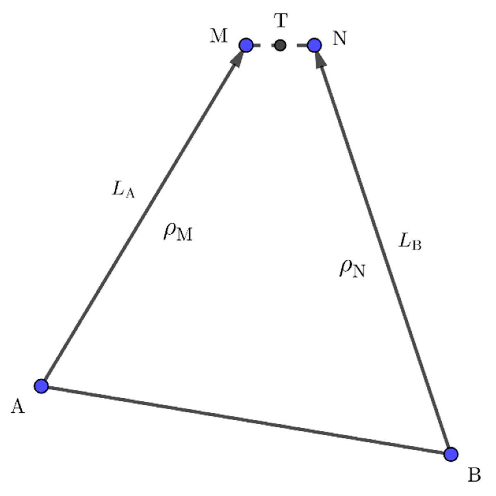
Figure 1. Two-site observation.
Remotesensing 13 04878 g001
Figure 2. The right ascension and declination of an LOS vector.
Remotesensing 13 04878 g002
Figure 3. Error analysis of triangulation.
Remotesensing 13 04878 g003
Figure 4. The mean altitude distribution of the 702 pieces of TLE-cataloged LEO space debris.
Remotesensing 13 04878 g004
Figure 5. The RMS position errors for LEO space debris.
Remotesensing 13 04878 g005
Figure 6. Distribution (percentage) of IOD SMA errors.
Remotesensing 13 04878 g006
Figure 7. Distribution (percentage) of IOD eccentricity errors.
Remotesensing 13 04878 g007
Figure 8. Distribution (percentage) of IOD inclination errors.
Remotesensing 13 04878 g008
Publisher’s Note: MDPI stays neutral with regard to jurisdictional claims in published maps and institutional affiliations.