Article

Performance Assessment of BDS-2/BDS-3/GPS/Galileo Attitude Determination Based on the Single-Differenced Model with Common-Clock Receivers

1
School of Geography and Information Engineering, China University of Geosciences (Wuhan), Wuhan 430074, China
2
School of Geodesy and Geomatics, Wuhan University, Wuhan 430079, China
3
Key Laboratory of Geospace Environment and Geodesy, Ministry of Education, Wuhan University, Wuhan 430079, China
*
Author to whom correspondence should be addressed.
Remote Sens. 2021, 13(23), 4845; https://doi.org/10.3390/rs13234845
Submission received: 3 October 2021 / Revised: 20 November 2021 / Accepted: 26 November 2021 / Published: 29 November 2021

Abstract

:
Global navigation satellite system (GNSS)-based attitude determination has been widely applied in a variety of fields due to its high precision, no error accumulation, low power consumption, and low cost. Recently, the emergence of common-clock receivers and construction of GNSS systems have brought new opportunities for high-precision GNSS-based attitude determination. In this contribution, we focus on evaluating the performance of the BeiDou regional navigation satellite system (BDS-2)/BeiDou global navigation satellite system (BDS-3)/Global Positioning System (GPS)/Galileo navigation satellite system (Galileo) attitude determination based on the single-differenced (SD) model with a common-clock receiver. We first investigate the time-varying characteristics of BDS-2/BDS-3/GPS/Galileo line bias (LB) with two different types of common-clock receivers. The results have confirmed that both the phase and code LBs are relatively stable in the time domain once the receivers have started. However, the phase LB is expected to change to an arbitrary value after each restart of the common-clock receivers. For the first time, it is also found that the phase LBs of overlapping frequencies shared by different GNSS systems are identical. Then, we primarily evaluated the performance of BDS-2/BDS-3/GPS/Galileo precise relative positioning and attitude determination based on the SD model with a common-clock receiver, using a static dataset collected at Wuhan. Experimental results demonstrated that, compared with the double-differenced (DD) model, the SD model can deliver a comparable root–mean–square (RMS) error of yaw but a significantly smaller RMS error of pitch, whether for BDS-2, BDS-3, GPS, or Galileo alone or a combination of them. The improvements of pitch accuracy are approximately 20.8–47.5% and 40.7–57.5% with single- and dual-frequency observations, respectively. Additionally, BDS-3 can deliver relatively superior positioning and attitude accuracy with respect to GPS and Galileo, due to its better geometry. The three-dimensional positioning and attitude (including yaw and pitch) accuracy for both the DD and SD models can be remarkably improved by the BDS-2, BDS-3, GPS, and Galileo combination with respect to a single system alone.

1. Introduction

Global navigation satellite system (GNSS)-based attitude determination has been extensively investigated over the past few decades and has proven to be a cost-effective and reliable means to obtain three-dimensional high-precision attitude information (i.e., yaw, pitch, and roll) for land vehicles, ships or aircrafts [1,2,3,4,5]. Due to its advantages of high-precision, no error accumulation, low power consumption, and low cost [6], GNSS-based attitude determination has extensive applications in military and civil fields.
The prerequisite for GNSS-based attitude determination is obtaining high-precision (centimeter or millimeter level) baseline vectors between antennas that are rigidly mounted to a platform with GNSS carrier phase relative positioning. Since the double-differenced (DD) model can eliminate or largely reduce the common errors in the satellite, receiver, and signal propagation path, it can retain the integer nature of ambiguities and thus has been widely used in GNSS-based attitude determination to obtain accurate ambiguity-fixed baseline solutions [7,8,9,10,11,12,13,14,15]. A well-known problem with the DD model is that the achievable accuracy of the baseline vectors in the vertical component is two to three times inferior to that in the horizontal components [16,17,18], which further results in significantly lower accuracy of pitch and roll than yaw. This phenomenon is caused by the strong vertical geometry inhomogeneity of the satellite sky distribution (which could result in the fact that some systematic biases in the observations could propagate more adversely in the vertical component of the baseline vector) and the high correlation between vertical component and the estimated receiver clock or tropospheric parameters [16,17].
The standard solution to this problem is based on the use of common-clock receivers and the single-differenced (SD) model. A critical feature of these common-clock receivers is that the navigation signals from multi-antennas are synchronized using a common clock, e.g., Trimble BD982/BD992, Javad Triumph-4×, and ComNav K582 [19]. Therefore, the clock errors for both the reference and rover stations are identical and can be eliminated with only the SD model, and the high correlation between vertical component and the receiver clock can be eliminated. However, when this approach is adopted, additional phase and code line bias (LB) parameters, which are composed of the initial phase bias in the receiver and hardware delays (from the antenna, receiver, and cable), are introduced and should be carefully taken into account. Although the phase LB could change after the receiver restarts, it is relatively stable during a continuous observation period once started [20,21]. Therefore, the phase LB is generally modeled as constant [21,22,23,24,25]. Zhang et al., further demonstrated that the phase LB could drift approximately 0.1 cycles during a continuous observation period of approximately one day if different length cables were used for connecting the antennas and the common-clock receiver. Furthermore, the LB variation was found to be a random walk process [26]. After proper handling of this troublesome LB, the SD model can improve the model strength, and thus significantly improve the accuracy of the baseline vector in the vertical component as well as the accuracy of pitch and roll [17,18,21,22,26,27].
Currently, a number of studies have been carried out to research GNSS-based attitude determination with the SD model, but most of them only considered the Global Positioning System (GPS)/Global Navigation Satellite System (GLONASS), and only few studies have examined the BeiDou regional navigation satellite system (BDS-2). For example, Li et al., presented a procedure for the GPS-based attitude determination using SD and DD carrier-phase observations simultaneously [24]; Keong and Lachapelle presented a model and performance of GPS/GLONASS attitude determination with SD observations from a common-clock receiver [22]; Zhang et al., presented the mathematical model and performance assessment of BDS-2/GPS SD attitude determination [28]. The GNSS systems have developed rapidly in recent years. Since a multi-GNSS combination can increase redundancy, strengthen geometry, and thus improve the accuracy, availability, and reliability of positioning and attitude determination [29,30,31], it is a trend of GNSS technology and applications. The BeiDou global navigation satellite system (BDS-3) construction has officially been announced as complete, with 30 satellites in orbit on 31 July 2020. The current BeiDou navigation satellite system (BDS) full constellation comprises 45 satellites, including 15 BDS-2 and 30 BDS-3 [32]. On 15 December 2016, the Galileo navigation satellite system (Galileo) was declared to independently provide initial services for users around the world [33]. Currently, 26 Galileo satellites are in orbit and 21 of them are usable [34]. However, to our knowledge, no study to date has considered SD attitude determination with Galileo and BDS-3. Consequently, it is of interest to investigate the performance of BDS-2/BDS-3/GPS/Galileo individually and in combination.
In this contribution, we focus on evaluating the performance of BDS-2/BDS-3/GPS/Galileo attitude determination with the SD model, using raw data collected with common-clock receivers. We first investigate the time-varying characteristics of phase and code LBs for BDS-2/BDS-3/GPS/Galileo. Then, we present performance assessment of the SD model with common-clock receiver for BDS-3/BDS-2/GPS/Galileo, using both single- and dual-frequency observations. The performance of the SD model is also compared with the DD model to illustrate its benefits in precise relative positioning and attitude determination. The main contribution of this work lies in new data processing and analysis with current BDS-2/BDS-3/GPS/Galileo constellations. The contributions of this work are presented as follows: (1) we have comprehensively investigated the time-varying characteristics of code as well as phase LBs for BDS-2/BDS-3/GPS/Galileo multiple navigation signals. Additionally, for the first time, we found that the phase LBs of overlapping frequencies shared by different GNSS systems are identical; (2) we have presented initial assessment and comparison of the baseline solution and attitude determination performance of SD and DD models with current BDS-2, BDS-3, GPS, and Galileo, alone and in combination.

2. Method

This section briefly introduces the mathematical models of SD and DD relative positioning based on common-clock receivers, as well as the direct computation of attitude information, including yaw and pith with only one baseline.

2.1. Functional Model

The undifferenced GNSS observation equation for code and phase can be expressed as:
P k , i s q = ρ k s q + c d t k c d t s q + d k , i s d i s q + I k , i s q + T k , i s q + ε k , i s q ϕ k , i s q = ρ k s q + c d t k c d t s q + λ i ( δ k , i s δ i s q + φ k , i s φ i s q + N k , i s q ) I k , i s q + T k , i s q + e k , i s q
where the superscript s  indicates that the parameter is related to the GNSS system, and s q indicates a certain satellite of system s ; The subscript k indicates the receiver; i is the frequency and λ i the corresponding wavelength; P and ϕ are the code and carrier phase observations in meters, respectively; ρ is the geometric distance between the receiver and the satellite; d t k  and d t s q are the clock errors of the receiver and satellite, respectively; d k , i s and d i s q are the code hardware delays of the receiver and the satellite, respectively; δ k , i s and δ i s q are the phase hardware delays of the receiver and the satellite, respectively; φ k , i s and φ i s q are the initial phase biases of the receiver and satellite, respectively; N is the integer ambiguity; I and T are the ionospheric and tropospheric delays, respectively; ε and e are the sum of noise and other unmodeled errors (e.g., the multipath error) for code and phase observations, respectively.
The SD observations between receivers can eliminate the satellite-specific errors such as satellite clock error and satellite hardware delay. Meanwhile, since only short baselines are involved in GNSS-based attitude determination, the ionospheric and tropospheric delays are negligible. Particularly, for common-clock receivers, since signals from the multiple antennas are synchronized by a single oscillator [19], the clock errors for both the reference and rover stations are identical. The relative clock error between receivers is therefore also eliminated. The SD observation equation between stations k and l with common-clock receivers is then given as:
Δ P k l , i s q = Δ ρ k l , i s q + Δ d k l . i s + Δ ε k l , i s q Δ ϕ k l , i s q = Δ ρ k l , i s q + λ i ( δ ¯ k l , i s + Δ N k l , i s q ) + Δ e k l , i s q
where Δ is SD operator between receivers, which denotes Δ ( · ) k l = Δ ( · ) k Δ ( · ) l ; Δ d k l . i s is the code hardware delay between receivers, which is also referred to code LB; δ ¯ k l , i s = Δ δ k l , i s + Δ φ k l , i s is the phase LB, which is composed of the between-receiver phase hardware delay ( Δ δ k l , i s ) and initial phase bias ( Δ φ k l , i s ). Since the initial phase bias will change to an arbitrary value after receivers are reset or restarted [35], the phase LB is expected to change to an arbitrary value after receivers are reset or restarted.
In Equation (2), the SD ambiguity is linearly correlated with the phase LB parameter, which will lead to rank deficiency of the normal equation. The rank deficiency equals to the number of systems multiplied by the number of frequencies and can be eliminated by the following re-parameterization:
Δ ϕ k l , i s q = Δ ρ k l , i s q + λ i ( δ ^ k l , i s + Δ N k l , i s q s 1 ) + Δ e k l , i s q ,
where, δ ^ k l , i s = Δ δ ¯ k l , i s + Δ N k l , i s , Δ N k l , i s q s 1 = Δ N k l , i s q Δ N k l , i s 1 . The SD ambiguity of a non-pivot satellite ( Δ N k l , i s q ) is re-parameterized as the SD ambiguity of the pivot satellite ( Δ N k l , i s 1 ) plus the DD ambiguity ( Δ N k l , i s q s 1 ) between non-pivot and pivot satellites. Furthermore, the phase LB parameter is lumped together with the SD ambiguity of the pivot satellite.
Then, the SD observation equation with common-clock receivers is given as:
Δ P k l , i s q = Δ ρ k l , i s q + Δ d k l . i s + Δ ε k l , i s q Δ ϕ k l , i s q = Δ ρ k l , i s q + λ i ( δ ^ k l , i s + Δ N k l , i s q s 1 ) + Δ e k l , i s q
According to Equation (4), the lumped LB parameter can be estimated simultaneously with baseline vector, code LB, and the DD ambiguities in both single-epoch or multi-epoch solutions. However, since the SD ambiguity of the pivot satellite is contained in the lumped phase LB, the lumped phase LB parameter should be reset once the pivot satellite changes or cycle slip occurs, when they are estimated in the multi-epoch solutions. An alternative solution is transforming the lumped phase LB using the resolved DD ambiguities.
When DD observations are created between two satellites and two stations, the code and phase LB parameters in Equation (2) can be further eliminated. Then, the DD observation equation between non-pivot satellite s q and pivot satellite s 1 can be expressed as:
Δ P k l , i s q s 1 = Δ ρ k l , i s q s 1 + Δ ε k l , i s q s 1 Δ ϕ k l , i s q s 1 = Δ ρ k l , i s q s 1 + λ i · Δ N k l , i s q s 1 + Δ e k l , i s q s 1 ,
where Δ is DD operator, which denotes Δ ( · ) s q s 1 = Δ ( · ) s q Δ ( · ) s 1 .
According to Equations (4) and (5), it is found that the redundancy of the SD model is identical to that of the DD model in the single-epoch solution. However, if the code and phase LBs are appropriately handled or modeled in multi-epoch solutions, the redundancy of the SD model could be larger than the DD model and result in improved performance of precise relative positioning and attitude determination. This is reasonable considering that the code and phase LBs are relatively stable during a continuous observation period, which will be further confirmed in Section 3 of this contribution.

2.2. Stochastic Model

The following elevation-dependent weighting function [36] was adopted for undifferenced observations in the stochastic model:
σ ( θ ) 2 = a 2 + b 2 / sin 2 ( θ ) ,
where σ ( θ ) 2 is the variance of undifferenced observations and θ is the satellite elevation angle. a and b are model coefficients with specified empirical values.

2.3. Direct Computation of Attitude

The attitude parameters (including yaw and pitch) from one baseline can directly be computed from the local-level coordinates. The formula for direct computation of attitude is given as [37]:
y a w = arctan ( b e b n ) , p i t c h = arctan ( b u b n 2 + b e 2 ) ,
where be, bn and bu are the baseline components in the east, north, and up, respectively.

3. Results

In this section, we first introduce the experimental data involved in this research. Then, we present results of LB estimation and characterization and assess the performance of precise relative positioning and attitude determination with SD and DD models.

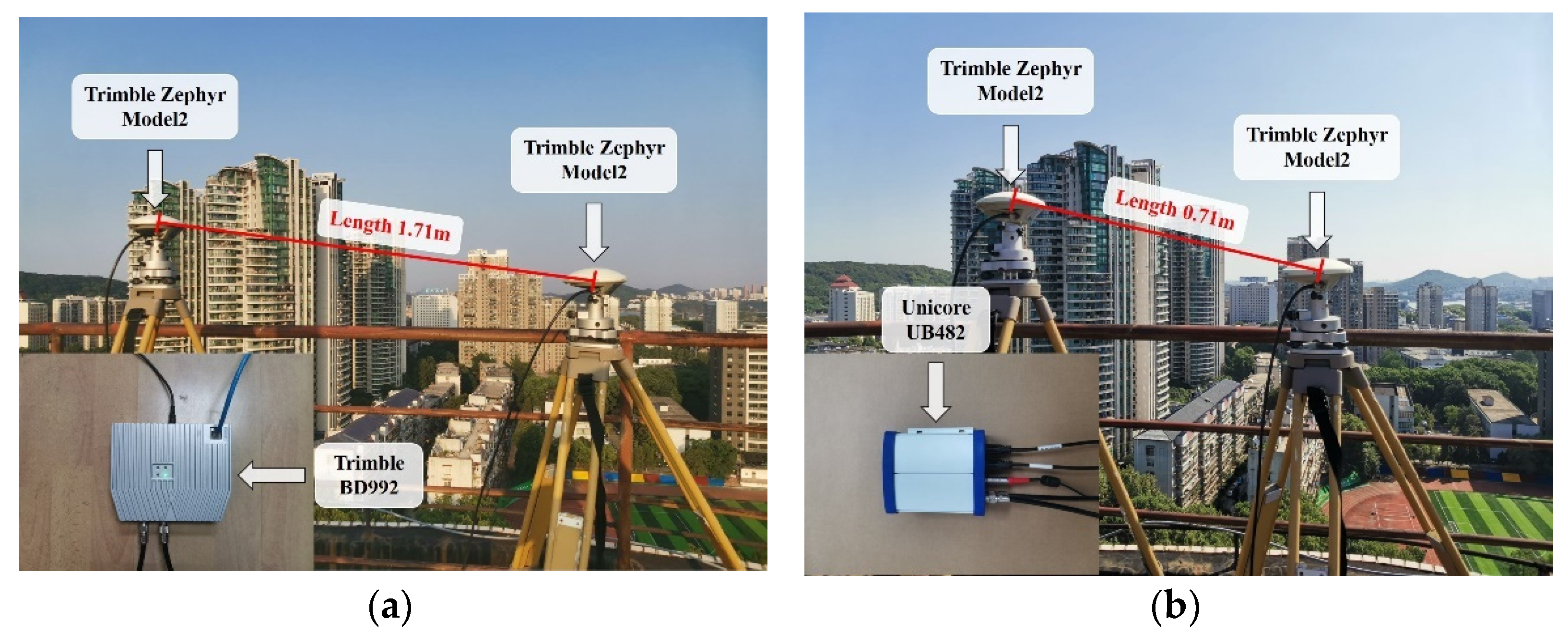
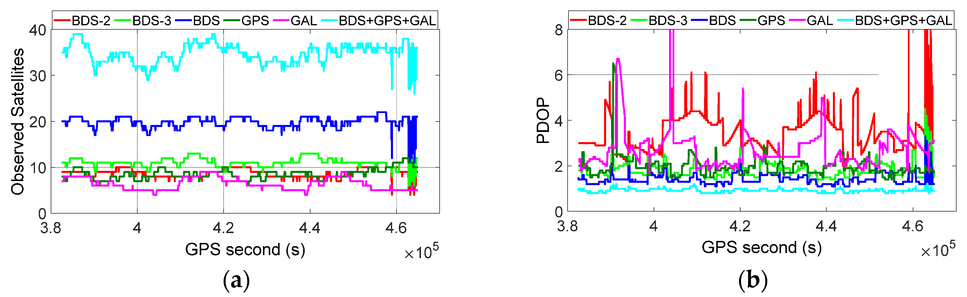
3.1. Data Collection

Two short baseline datasets, collected from static experiments on the roof of the teaching experiment building at the Wuhan University campus, were used in this research. For the two datasets, two Trimble Zephyr Model2 antennas were employed, the elevation cutoff angle was 10°, and the sampling interval was 1 s. Dataset 1 was collected using a Trimble BD992 common-clock receiver (or original equipment manufacturer (OEM) board) with a baseline length of approximately 1.71 m, from 18:15, 1 April to 19:30, 2 April 2021, GPS time (GPST). Dataset 2 was collected using a Unicore UB482 common-clock receiver (or OEM board) with a baseline length of approximately 0.71 m, from 16:45, 26 July to 09:45, 27 July 2021 GPST. Table 1 lists the information of the two involved static experiments. The observational conditions and GNSS receivers and antennas used in the experiments are shown in Figure 1. It is observed that the datasets were collected in a relatively open-sky observational environment. We should note that two cables with the same length and material were used to connect the GNSS receiver and antennas in our experiments.

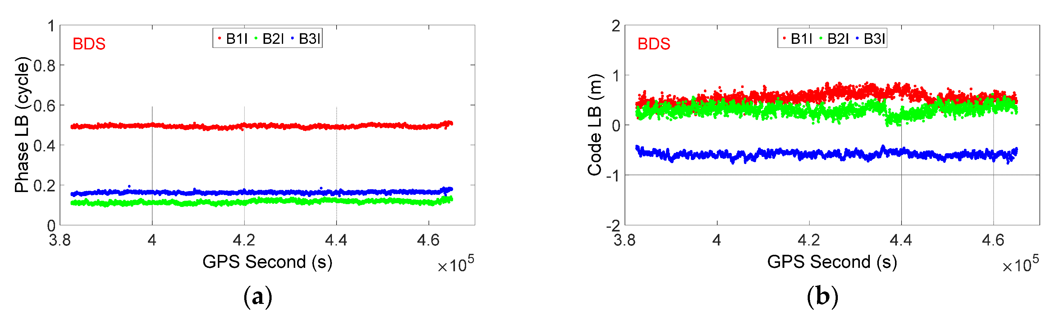
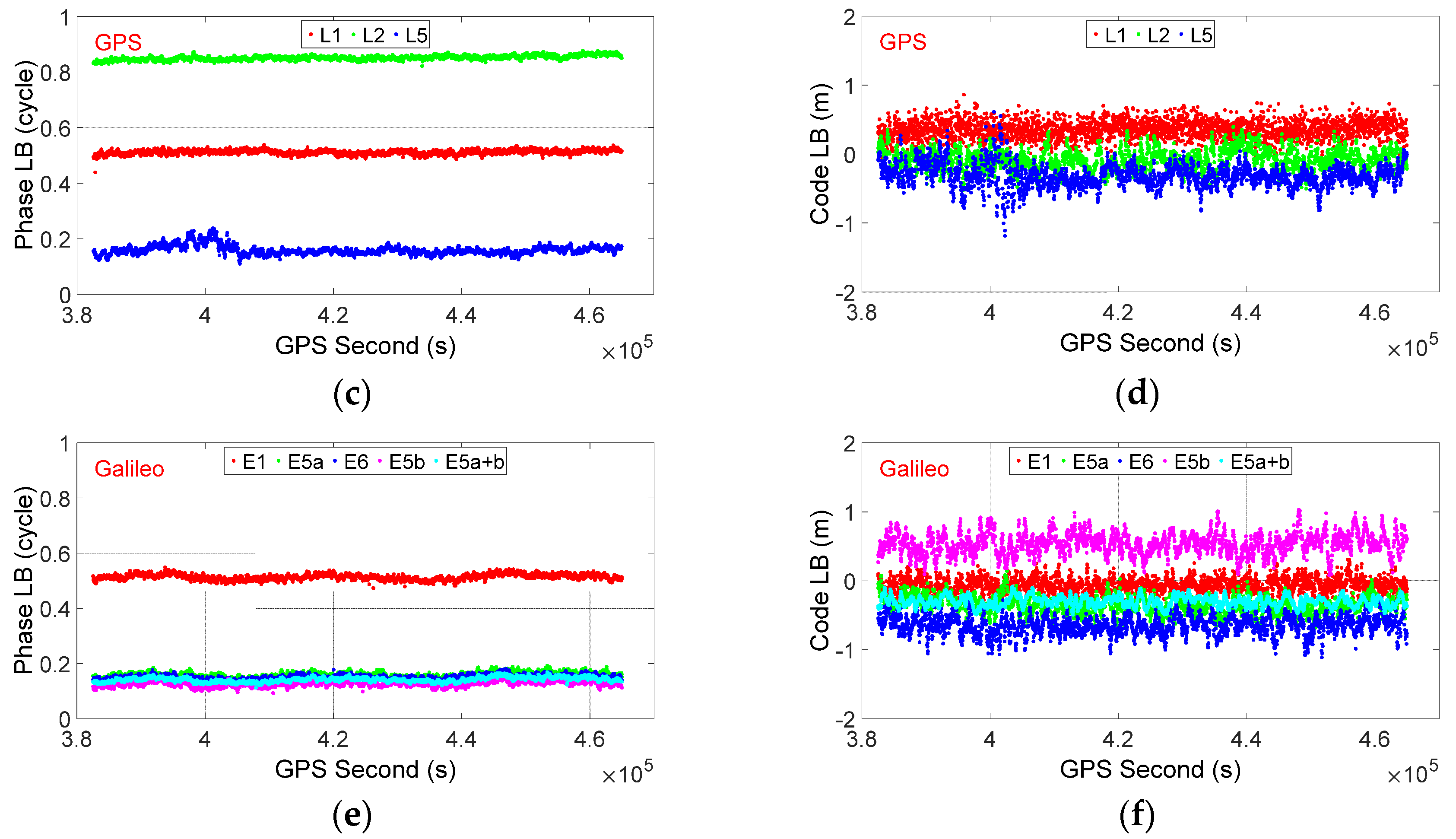
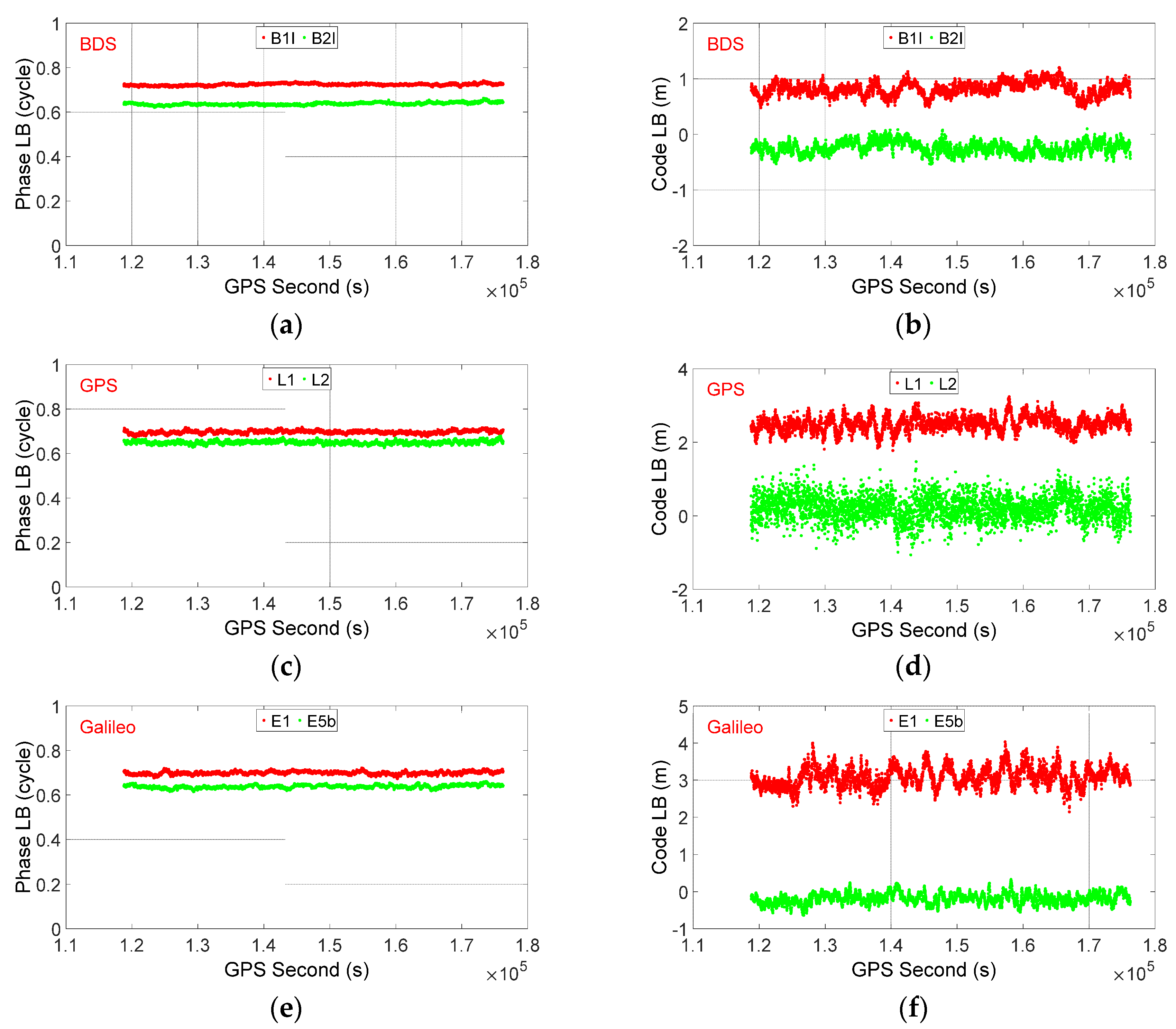
3.2. LB Estimation and Characterization

In this subsection, we estimate and analyze the characteristics of phase and code LBs for BDS/GPS/Galileo. According to Equations (4) and (6), the mathematical model is first constructed. Then, the code and lumped phase LB parameters, as well as the DD ambiguities, are estimated epoch-wise under a 10° elevation cutoff angle with precise known baseline vectors, which are represented by post-processed fixed static baseline solutions with multi-GNSS observations over the entire observation period. After that, the ambiguities can be resolved reliably with the popular least-squares ambiguity decorrelation adjustment (LAMBDA) method [38], and finally, the LB parameters are achieved with fixed ambiguities. Only the fractional part of the phase LB is considered, since the integer part can be absorbed by the DD ambiguity parameters.
Figure 2 and Figure 3 show the phase and code LB series for BDS/GPS/Galileo with Trimble BD992 and Unicore UB482, respectively. The corresponding statistics, including the mean values and standard deviations (STDs), are listed in Table 2 and Table 3. It is observed that, overall, the phase and code LBs are relatively stable during the entire observation period, though small variations are also present. The STDs for BDS/GPS/Galileo phase LB varied from approximately 0.005 to 0.016 cycles for both Trimble BD992 and Unicore UB482, which is at the same level of phase noise. The STDs for the code LB are approximately 0.05 to 0.17 m for Trimble BD992 while they are approximately 0.11 to 0.33 m for Unicore UB482, which are at the same level of code noise.
Moreover, we find that the mean values for the phase LBs are generally different for signals with different frequencies. However, for signals of different GNSS systems with overlapping frequencies, the mean values for phase LB are identical. For example, for Trimble BD992, the mean values for GPS L1/L2 and BDS B1I/B2I signals are different with values of 0.512, 0.851, 0.494, and 0.115 cycles, respectively. Meanwhile, the mean values of phase LBs for GPS L1/L5 signals are 0.512/0.159 cycles, which can be regarded as equal to Galileo E1/E5a signals (0.514/0.159 cycles), implying that the phase observations from overlapping frequencies of different GNSS systems can simply be treated as if they are from one constellation in the SD model. For code LBs, the values for different signals are generally below 1.0 m, except for GPS L1 and Galileo E1 signals of Unicore UB482. Moreover, it seems that the code LBs for the overlapping frequencies of different systems also have similar values. For example, the code LBs for GPS L5/Galileo E5a are −0.32/−0.36 m, but it is also noticed that discrepancy is observed between the code LBs of GPS L1 and Galileo E1. We assume that this may be caused by the difference in residual errors between the two signals.
As demonstrated in Section 2, the phase LB is expected to change to an arbitrary value after the receivers restart, due to its inclusion of the initial phase bias in the receiver. Consequently, we have also carried out several experiments to investigate the impact of receiver restart on LB estimates. In these experiments, different sessions of observation are collected with the same equipment and observation condition, but the common-clock receiver is restarted after data collection in each session. As an example, Table 4 shows the estimated phase and code LBs before and after receiver restart in a representative experiment with Trimble BD992 (the experimental dataset was collected from 02:20, 10 April to 00:50, 12 April 2021 GPST. The receiver was rebooted at 11:33, 10 April 2021 GPST, and divided the dataset into two sessions). It was found that the code LB remained invariable after receiver restart. However, an obvious change was observed in the phase LB after receiver reboot. Taking GPS L1/L2/L5 signals as examples, the phase LBs are 0.984, 0.190, and 0.714 cycles for Session 1 and changed to 0.229, 0.418, and 0.203 cycles for Session 2. Similar results are also observed for other experiments but are not presented herein, for simplicity. Such results confirm the theoretical analysis in Section 2 and imply that the a priori-calibrated phase LB in one dataset could not be used as corrections for other datasets if the receiver is restarted. Consequently, the phase LB should be estimated and modeled during a continuous observation period in real-time applications. Additionally, it is observed that the code LBs remain almost unchanged after receiver restart.

3.3. Performance Assessment of Attitude Determination with SD and DD Models

In this subsection, raw BDS-2/BDS-3/GPS/Galileo data collected with Trimble BD992 common-clock receiver is processed to evaluate the performance of precise relative positioning and attitude determination with SD and DD models. The performance of BDS-2, BDS-3, GPS, and Galileo alone and in combination are evaluated and compared using both single-frequency (BDS-2/BDS-3 B1I, GPS L1, and Galileo E1) and dual-frequency (BDS-2/BDS-3 B1I/B3I, GPS L1/L2, and Galileo E1/E5a) observations.
The data processing procedure of both SD and DD models can be divided into the following steps. First, the mathematical model (Equations (4) and (6) for the SD model, and Equations (5) and (6) for DD model) is constructed. Then, the float solution is obtained through parameter estimation. The baseline vector is estimated simultaneously with the ambiguities for the DD model and ambiguities and LB parameters for the SD model. After that, the ambiguities are resolved with the LAMBDA method [38] and fixed solution is obtained. Finally, the attitude is directly computed with a fixed baseline vector.
In the data processing, the baseline is processed with moving-baseline mode and the parameters are real-time estimated with a Kalman filter in multi-epoch solutions. Since only ultra-short baselines are involved, the ionospheric and tropospheric delays are neglected. The elevation cutoff angle is set to 10°. The elevation-dependent model in Equation (6) is adopted in the stochastic model, and the model coefficients (a and b) are all set as 3 mm and 0.3 m for phase and code observations, respectively. The popular ratio test, introduced by Euler and Schaffrin [39], with a fixed critical value, is adopted for ambiguity validation. The critical value is set at 2.0 for GPS, Galileo, BDS-2, and BDS-3 alone, and 1.5 for a combination of them, considering that the model strength is much improved by multi-GNSS combination. As demonstrated in Section 3.2, although the phase and code LBs are relatively stable in the time domain, the epoch-by-epoch phase and code LBs still have small variations and several millimeters and decimeters of noise, respectively. As a consequence of this, we adopt a random walk with relatively low process noise in the real-time estimation, to capture the time-constant characteristics with small variations for both phase and code LB parameters. The detailed data processing strategies for SD and DD models are listed in Table 5.
As a representative example, Dataset 1 was processed and analyzed to show the benefits of the SD model with respect to the DD model in terms of ambiguity resolution success rate, as well as accuracy of baseline solution and attitude determination. The success rate is defined as the number of epochs with ambiguities correctly resolved divided by the total epoch numbers. The ambiguities are regarded as correctly resolved only if the ratio is no less than the critical value. Meanwhile, the positioning errors should be less than 4 cm/4 cm/8 cm in the east (E)/north (N)/up (U) components compared with true baseline vector, which is the post-processed fixed static baseline solution with BDS-2/BDS-3/GPS/Galileo observations over the entire observation period. The positioning accuracy is defined as the root–mean–square (RMS) of the positioning errors of correctly resolved solutions. Similarly, the attitude accuracy is defined as the RMS of the attitude errors of correctly resolved solutions with respect to the true attitude, which is directly computed from the true baseline vector. It is well-known that the attitude accuracy increases for larger antenna separations, and in this contribution, we further convert the RMS errors of attitude from the baseline length of 1.71 m to 1.0 m.
Figure 4 shows the number of observed BDS-2/BDS-3/GPS/Galileo satellites as well as their corresponding position dilution of precision (PDOP) series for Dataset 1, under the 10° elevation cutoff angle. It is observed that the numbers of tracked satellites were 4–10, 6–13, 6–12, and 4–9 for BDS-2, BDS-3, GPS, and Galileo, respectively. For combined multi-GNSS systems, the numbers of tracked satellites increased to 11–22 and 26–39 for combined BDS-2/BDS-3 and BDS-2/BDS-3/GPS/Galileo, respectively. The corresponding PDOP values were approximately 2.0–6.1, 1.3–4.5, 1.4–2.9, 1.7–6.7, 1.1–3.3, and 0.8–1.2 for BDS-2, BDS-3, GPS, Galileo, BDS-2/BDS-3, BDS-2/BDS-3/GPS/Galileo, respectively. The average numbers of visible satellites during the observation period were 8.8, 11.1, 8.5, 6.4, 19.9, and 34.8, while the average PDOPs were 3.37, 1.79, 1.97, 2.78, 1.40, and 0.92, respectively. These results demonstrate that the current BDS-2, BDS-3, GPS, and Galileo constellation can independently provide services with sufficient satellites and relatively good geometry. Moreover, the current BDS-2/BDS-3 constellation can provide much better geometry than GPS and Galileo, and the geometry can be significantly improved with multi-constellation integration.
Figure 5 shows the positioning errors of correctly resolved solutions in the east, north, and up components with SD and DD models, using BDS-2/BDS-3/GPS/Galileo dual-frequency observations under the 10° cutoff elevation angle. As shown, compared with the DD model, the SD model can deliver comparable positioning errors in the east and north components, and obviously smaller positioning errors in the up component, whether for BDS-2, BDS-3, GPS, and Galileo alone or a combination of them. Moreover, whether for the SD or DD model, the three-dimensional positioning errors of combined BDS-2/BDS-3/GPS/Galileo are significantly reduced compared with BDS-2, BDS-3, GPS, and Galileo alone.
Table 6 further lists the ambiguity resolution success rates and the positioning RMS values for SD and DD models, using BDS-2/BDS-3/GPS/Galileo single- and dual-frequency observations under the 10° elevation cutoff angle. In line with Figure 5, we observe that compared with the DD model, comparable positioning RMS values are achieved in the east and north components, whereas significant improvements are obtained in the up components when the SD model is adopted. If single-frequency observations are used, the improvements in the up component are 21.0%, 45.8%, 47.1%, 46.0%, 25.9%, 31.8%, and 37.5% for BDS-2, BDS-3, GPS, Galileo, BDS-2/BDS-3, BDS-2/BDS-3/GPS, BDS-2/BDS-3/GPS/Galileo solutions, respectively. For the dual-frequency case, the improvements are 46.3%, 51.0%, 54.4%, 58.0%, 40.0%, 48.6%, and 48.4%, respectively. Moreover, it is observed that BDS-3 can provide better positioning accuracy with both SD and DD models than GPS and Galileo, due to its better geometry (cf. Figure 4). Remarkable improvements of positioning accuracy are further obtained with a multi-GNSS combination with respect the single GNSS system alone. Taking the dual-frequency observations with the SD model case as an example, the three-dimensional positioning RMS values in the east, north, and up components are (0.29, 0.32, 0.58), (0.20, 0.19, 0.24), (0.21, 0.23, 0.26), and (0.26, 0.26, 0.29) cm for BDS-2, BDS-3, GPS, and Galileo-only solutions, respectively. They are reduced to (0.16, 0.18, 0.27), (0.13, 0.13, 0.18), and (0.11, 0.12, 0.16) cm for combined BDS-2/BDS-3, BDS-2/BDS-3/GPS, and BDS-2/BDS-3/GPS/Galileo solutions, respectively. With regard to the ambiguity resolution (AR) performance, it is observed that all the ambiguity resolution success rates are more than 99.6% except for the BDS-2 single-frequency solution with the DD model. The SD model can generally deliver slightly higher ambiguity success rates than the DD model, which originates from the improvement of model strength of the SD model with respect to the DD model, as demonstrated in Section 2.
Figure 6 shows the attitude errors of correctly resolved solutions with SD and DD models using BDS-2/BDS-3/GPS/Galileo dual-frequency observations under the 10° cutoff elevation angle. As shown, compared with the DD model, the SD model can deliver comparable yaw errors and obviously smaller pitch errors, whether for BDS-2, BDS, GPS and Galileo alone or a combination of them. Moreover, whether for the SD or DD model, the attitude errors of combined BDS-2/BDS-3/GPS/Galileo are significantly reduced compared with BDS-2, BDS-3, GPS, and Galileo alone.
Table 7 further lists the attitude accuracy of the SD and DD models using BDS-2/BDS-3/GPS/Galileo single- and dual-frequency observations under the 10° elevation cutoff angle. We observe that compared with the DD model, the adoption of the SD model can achieve comparable accuracy for yaw but significantly better accuracy for pitch. The improvements of pitch accuracy for BDS-2, BDS-3, GPS, Galileo, BDS-2/BDS-3, BDS-2/BDS-3/GPS, and BDS-2/BDS-3/GPS/Galileo single-frequency solutions are approximately 20.8%, 47.1%, 47.5%, 46.0%, 29.0%, 32.0%, and 39.1%, respectively. Similar results are also obtained for the dual-frequency case. Moreover, BDS-3 can deliver better attitude accuracy with respect to GPS and Galileo. The attitude accuracy can be further improved by a combination of multi-GNSS systems. Taking the SD model with single-frequency observations as an example, the yaw and pitch RMSs are (0.18, 0.57), (0.14, 0.18), (0.16, 0.21), and (0.20, 0.27) degrees for BDS-2, BDS-3, GPS, and Galileo only solutions, respectively. They are reduced to (0.11, 0.22), (0.09, 0.17), and (0.09, 0.14) degrees for combined BDS-2/BDS-3, BDS/GPS, and BDS/GPS/Galileo solutions, respectively. It is noticed that the attitude accuracy of BDS-2 is lower than that of BDS-3, GPS, and Galileo, which is due to the poor geometry of BDS-2 in this experiment (cf. Figure 4).

4. Discussions

The recent emergence of commercial multi-GNSS common-clock receivers and construction of GNSS systems have brought new opportunities for high-precision GNSS-based attitude determination. Compared with previous research that mainly considered GPS/GLONASS [22,24], this contribution presents an initial assessment of attitude determination based on the SD model, using a common-clock receiver with current GPS/BDS-2/BDS-3/Galileo constellations. The experimental results have confirmed the advantages of the SD model over the DD model, as demonstrated in the literature [17,18,21,22,26,27], and further shown the potential of high-precision multi-GNSS (GPS/BDS-2/BDS-3/Galileo) attitude determination with a common-clock receiver. With regard to the characterization of LBs, for the first time, it is found that for overlapping frequencies shared by different GNSS systems, their phase LBs are identical and thus they can be simply treated as if they are from one constellation in the SD model. Moreover, in line with the theoretical analysis in previous literature [20,21], our numerical results have further confirmed that the phase LB could change to an arbitrary value after receivers restart, which suggests that the phase LB should be estimated in real-time rather than calibrated in advance.
It is noted that the conclusion regarding the stability of LBs in our research is based on the fact that two of the same cables and antennas are utilized. One should remember that they are affected by hardware delays from the antenna, receiver, and cable. Future research should therefore be carried out to investigate the stability of the LBs when two different cables or antennas are involved in the data collection. In-depth investigation on the characteristics of LBs with more types of commercial GNSS common-clock receivers is also required. In addition, only static tests are carried out in our research, kinematic tests will also be carried out to further evaluate the performance of attitude determination based on SD and DD models with multi-GNSS common-clock receivers in the future.

5. Conclusions

In this contribution, we focus on investigating the time-varying characteristics of LB parameters and evaluating the performance of BDS-2/BDS-3/GPS/Galileo precise relative positioning and attitude determination, based on the SD model with common-clock receivers. The performance of the SD model is compared with the DD model, using static data collected with a Trimble BD992 receiver at Wuhan. The following conclusions can be drawn:
(1)
Experimental results with Trimble BD992 and Unicore UB482 receivers have confirmed that both the phase and code LBs are relatively stable in the time domain once the receivers have started. However, the phase LB could change to an arbitrary value after each restart of the common-clock receivers. It is also found that the LBs for signals with overlapping frequencies, but from different GNSS systems (e.g., GPS/Galileo L1-E1 and L5-E5a), are equal, which implies that the observations from overlapping frequencies of different GNSS systems can be simply treated as if they are from one constellation in the SD model.
(2)
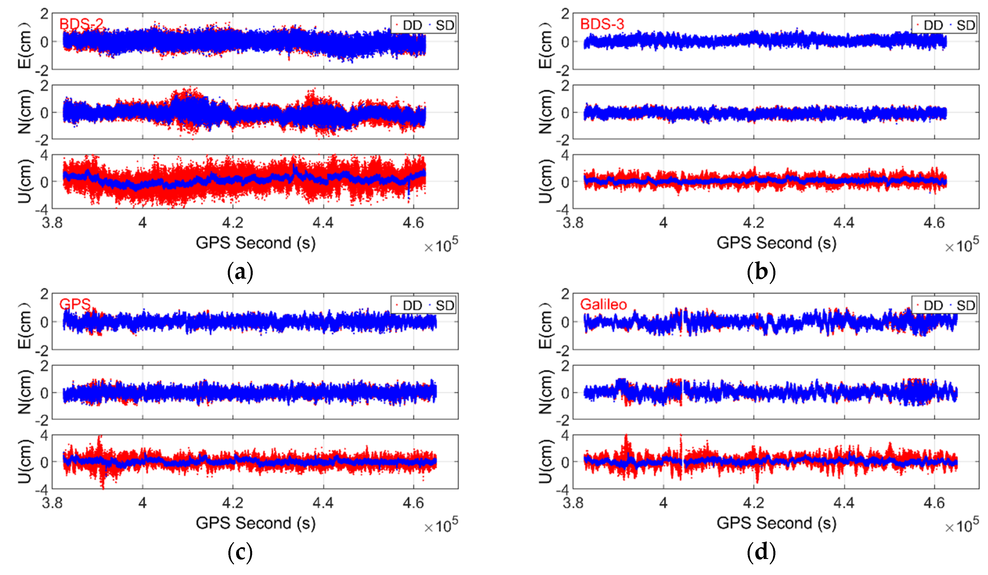
The positioning accuracy of the SD model is comparable to that of the DD model in the east and north components but significantly higher in the up component, whether for BDS-2, BDS-3, GPS, and Galileo only or combined solutions. The positioning RMS errors of the SD model are reduced by approximately 21.0–47.1% for single-frequency solutions and 40.0–58.0% for dual-frequency solutions with respect to the DD model.
(3)
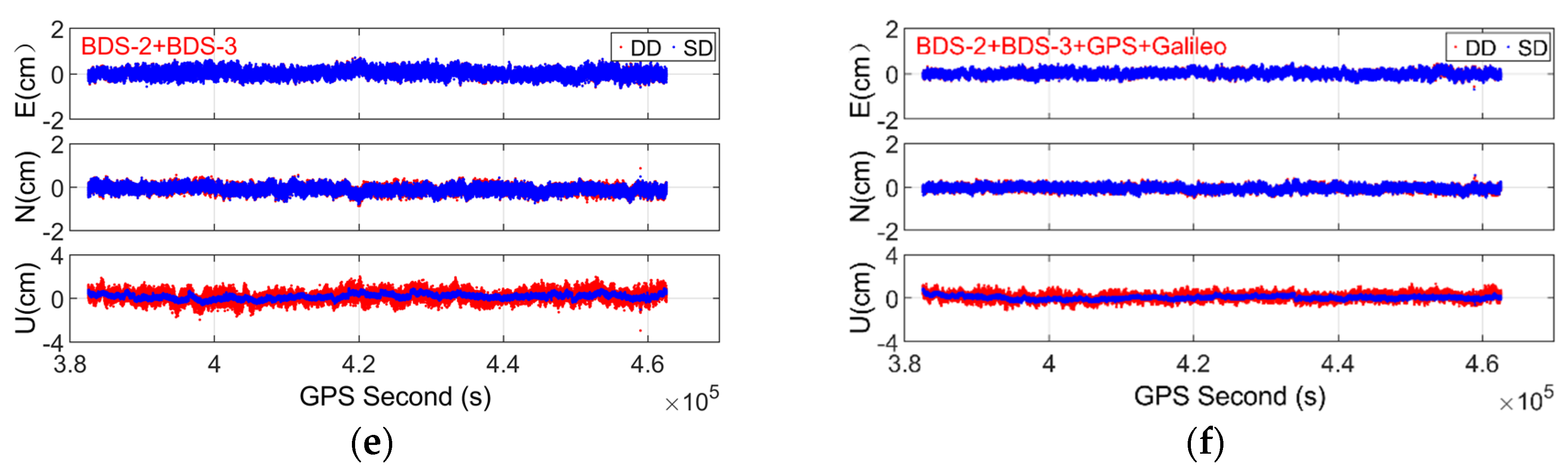
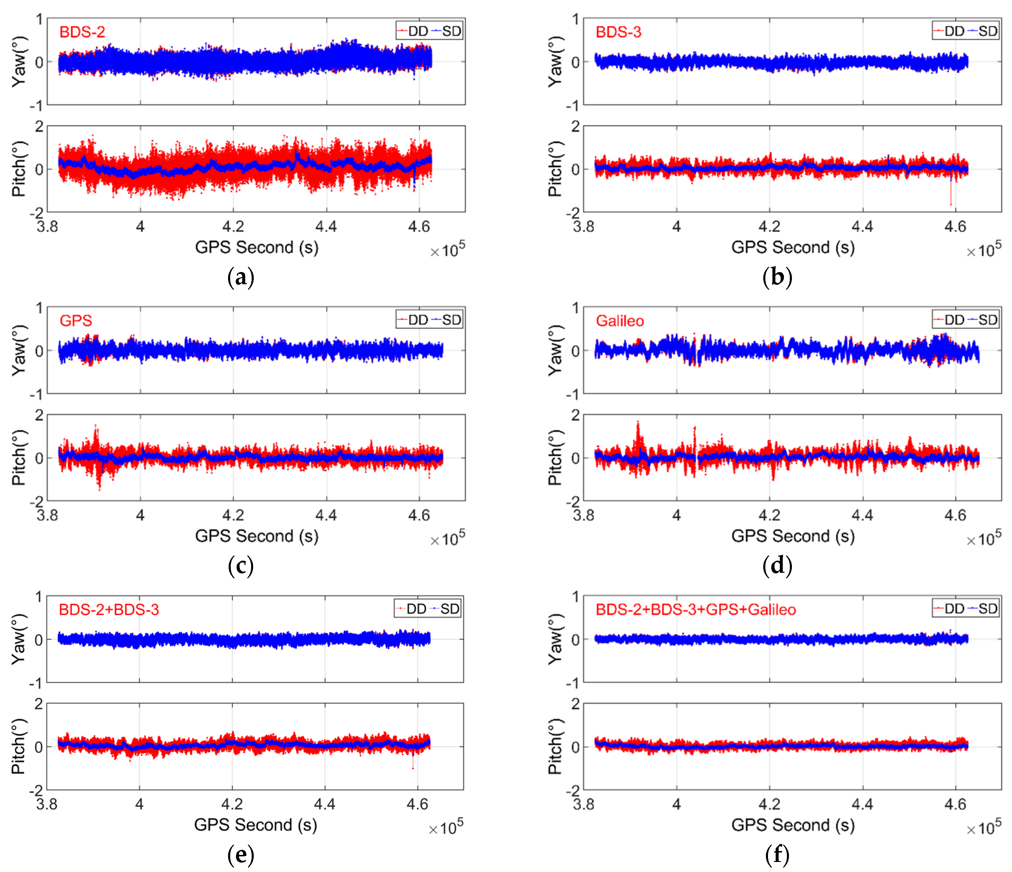
Compared with the DD model, the SD model can deliver comparable accuracy for yaw and significantly higher accuracy for pitch, whether for BDS-2, BDS-3, GPS, and Galileo alone or a combination of them. The RMS errors of pitch are reduced by approximately 20.8–47.5% and 40.7–57.5% with single- and dual-frequency observations, respectively.
(4)
The BDS-3 can deliver relatively better positioning and attitude accuracy with respect to GPS and Galileo, due to its better geometry. Compared with BDS-2, BDS-3, GPS, and Galileo-only solutions, the three-dimensional positioning and attitude (including yaw and pitch) accuracy for both the DD and SD models can be remarkably improved by a combination of multi-GNSS systems.

Author Contributions

Conceptualization, M.W. and W.L.; methodology, M.W., W.L. and W.W.; software, M.W., W.W. and S.L.; validation, S.L. and M.W.; formal analysis, M.W. and S.L.; writing—original draft preparation, S.L. and M.W.; writing—review and editing, M.W., and W.L. All authors have read and agreed to the published version of the manuscript.

Funding

This research was funded by the National Natural Science Foundation of China, grant numbers 41904035 and 41774031, Hubei Provincial Natural Science Foundation of China, grant number 2019CFB261, Technology Innovation Special Project (Major Program) of Hubei Province of China, grant number 2019AAA043, Key Laboratory of Geospace Environment and Geodesy, Ministry of Education, Wuhan University, grant number 19-01-06, Key Laboratory for Digital Land and Resources of Jiangxi Province, East China University of Technology, grant number DLLJ202106, and the Fundamental Research Funds for the Central University, China University of Geosciences (Wuhan), grant number CUGL180836.

Institutional Review Board Statement

Not applicable.

Informed Consent Statement

Not applicable.

Data Availability Statement

The raw GNSS observations are not publicly available. For more details, please contact the corresponding author by email: [email protected].

Acknowledgments

The authors appreciate the constructive and valuable comments from the anonymous reviewers.

Conflicts of Interest

The authors declare no conflict of interest.

References

  1. Teunissen, P.J.G.; Giorgi, G.; Buist, P.J. Testing of a new single-frequency GNSS carrier phase attitude determination method: Land, ship and aircraft experiments. GPS Solut. 2011, 15, 15–28. [Google Scholar] [CrossRef] [Green Version]
  2. Giorgi, G.; Teunissen, P.J.G.; Gourlay, T.P. Instantaneous global navigation satellite system (GNSS)-based attitude determination for maritime applications. IEEE J. Ocean. Eng. 2012, 37, 348–362. [Google Scholar] [CrossRef]
  3. Sabatini, R.; Kaharkar, A.; Bartel, C.; Shaid, T. Carrier-phase GNSS attitude determination and control for small UAV applications. J. Aeronaut. Aerosp. Eng. 2013, 2, 1–11. [Google Scholar]
  4. Willi, D.; Rothacher, M. GNSS attitude determination with non-synchronized receivers and short baselines onboard a spacecraft. GPS Solut. 2017, 21, 1605–1617. [Google Scholar] [CrossRef]
  5. Hauschild, A.; Mohr, U.; Markgraf, M.; Montenbruck, O. Flight results of GPS-based attitude determination for the microsatellite Flying Laptop. Navigation 2019, 66, 277–287. [Google Scholar] [CrossRef]
  6. Wang, Y.; Zhan, X.; Zhang, Y. Improved ambiguity function method based on analytical resolution for GPS attitude determination. Meas. Sci. Technol. 2007, 18, 2985–2990. [Google Scholar] [CrossRef]
  7. Li, Z.; Liu, W.; Lou, Y.; Zhou, Z. Heading determination algorithm with single epoch dual frequency GPS data. Geomat. Inf. Sci. Wuhan Univ. 2007, 32, 753–756. [Google Scholar]
  8. Dai, Z.; Knedlik, S.; Loffeld, O. A MATLAB toolbox for attitude determination with GPS multi-antenna systems. GPS Solut. 2009, 13, 241–248. [Google Scholar] [CrossRef]
  9. Teunissen, P.J.G. Integer least-squares theory for the GNSS compass. J. Geod. 2010, 84, 433–447. [Google Scholar] [CrossRef] [Green Version]
  10. Giorgi, G.; Teunissen, P.J.G.; Verhagen, S.; Buist, P.J. Testing a new multivariate GNSS carrier phase attitude determination method for remote sensing platforms. Adv. Space Res. 2010, 46, 118–129. [Google Scholar] [CrossRef] [Green Version]
  11. Nadarajah, N.; Teunissen, P.J.G.; Raziq, N. Instantaneous BeiDou–GPS attitude determination: A performance analysis. Adv. Space Res. 2014, 54, 851–862. [Google Scholar] [CrossRef] [Green Version]
  12. Zhang, X.; Wu, M.; Liu, W. Receiver time misalignment correction for GPS-based attitude determination. J. Navig. 2015, 68, 646–664. [Google Scholar] [CrossRef] [Green Version]
  13. Gan, Y.; Sui, L.; Xiao, G.; Zhang, Q.; Wang, L. Real-time GNSS attitude determination by a direct approach with efficiency and robustness. Meas. Sci. Technol. 2021, 32, 115904. [Google Scholar] [CrossRef]
  14. Wang, X.; Yao, Y.; Xu, C.; Zhao, Y.; Lv, D. An Improved Single-Epoch Attitude Determination Method for Low-Cost Single-Frequency GNSS Receivers. Remote Sens. 2021, 13, 2746. [Google Scholar] [CrossRef]
  15. Wu, S.; Zhao, X.; Pang, C.; Zhang, L.; Xu, Z.; Zou, K. Improving ambiguity resolution success rate in the joint solution of GNSS-based attitude determination and relative positioning with multivariate constraints. GPS Solut. 2020, 24, 31. [Google Scholar] [CrossRef]
  16. Santerre, R.; Beutler, G. A proposed GPS method with multi-antennae and single receiver. J. Geod. 1993, 67, 210–223. [Google Scholar] [CrossRef]
  17. Macias-Valadez, D.; Santerre, R.; Larochelle, S.; Landry, R. Improving vertical GPS precision with a GPS-over-fiber architecture and real-time relative delay calibration. GPS Solut. 2012, 16, 449–462. [Google Scholar] [CrossRef]
  18. Chen, W.; Qin, H.; Zhang, Y.; Tian, J. Accuracy assessment of single and double difference models for the single epoch GPS compas. Adv. Space Res. 2012, 49, 725–738. [Google Scholar] [CrossRef]
  19. Dong, D.; Chen, W.; Cai, M.; Zhou, F.; Wang, M.; Yu, C.; Zheng, Z.; Wang, Y. Multi-antenna synchronized global navigation satellite system receiver and its advantages in high-precision positioning applications. Front. Earth Sci. 2016, 10, 772–783. [Google Scholar] [CrossRef]
  20. Chen, W. A remark on the GNSS single difference model with common clock scheme for attitude determination. J. Appl. Geod. 2016, 10, 167–173. [Google Scholar] [CrossRef]
  21. Chen, W.; Yu, C.; Dong, D.; Cai, M.; Zhou, F.; Wang, Z.; Zhang, L.; Zheng, Z. Formal Uncertainty and Dispersion of Single and Double Difference Models for GNSS-Based Attitude Determination. Sensors 2017, 17, 408. [Google Scholar] [CrossRef] [PubMed] [Green Version]
  22. Keong, J.; Lachapelle, G. Heading and pitch determination using GPS/GLONASS. GPS Solut. 2000, 3, 26–36. [Google Scholar] [CrossRef]
  23. Alban, S. Design and Performance of a Robust GPS/INS Attitude System for Automobile Applications. Ph.D. Thesis, Stanford University, Stanford, CA, USA, 2004. [Google Scholar]
  24. Li, Y.; Zhang, K.; Roberts, C.; Murata, M. On-the-fly GPS-based attitude determination using single-and double-differenced carrier phase measurements. GPS Solut. 2004, 8, 93–102. [Google Scholar] [CrossRef]
  25. Park, K.; Crassidis, J.L. A Robust GPS receiver self-survey algorithm. Navigation 2006, 53, 259–268. [Google Scholar] [CrossRef] [Green Version]
  26. Zhang, L.; Hou, Y.; Wu, J. A drift line bias estimator: ARMA-based filter or calibration method, and its application in BDS/GPS-based attitude determination. J. Geod. 2016, 90, 1331–1343. [Google Scholar]
  27. Schön, S.; Pham, H.K.; Kersten, T.; Leute, J.; Bauch, A. Potential of GPS common clock single-differences for deformation monitoring. J. Appl. Geod. 2016, 10, 45–52. [Google Scholar] [CrossRef] [Green Version]
  28. Zhang, L.; Chen, W.; Yu, C.; Dong, D. Attitude Determination based on Common Reference Clock GPS/BDS Dual Antenna. In Proceedings of the 4th International Conference on Information Systems and Computing Technology (ISCT 2016), Advances in Computer Science Research, Shanghai, China, 22–23 December 2016. [Google Scholar]
  29. Nadarajah, N.; Teunissen, P.J.G. Instantaneous GPS/Galileo/QZSS/SBAS attitude determination: A single-frequency (L1/E1) robustness analysis under constrained environments. Navigation 2014, 61, 65–75. [Google Scholar] [CrossRef] [Green Version]
  30. Li, X.; Ge, M.; Dai, X.; Ren, X.; Fritsche, M.; Wickert, J.; Schuh, H. Accuracy and reliability of multi-GNSS real-time precise positioning: GPS, GLONASS, BeiDou, and Galileo. J. Geod. 2015, 89, 607–635. [Google Scholar] [CrossRef]
  31. Odolinski, R.; Teunissen, P.J.G. Low-cost, 4-system, precise GNSS positioning: A GPS, Galileo, BDS and QZSS ionosphere-weighted RTK analysis. Meas. Sci. Technol. 2017, 28, 125801. [Google Scholar] [CrossRef] [Green Version]
  32. Constellation Status. Available online: http://www.csno-tarc.cn/system/constellation (accessed on 26 September 2021).
  33. Wu, W.; Guo, F.; Zheng, J. Analysis of Galileo signal-in-space range error and positioning performance during 2015–2018. Sat. Nav. 2020, 1, 6. [Google Scholar] [CrossRef] [Green Version]
  34. Constellation Information. Available online: https://www.gsc-europa.eu/system-service-status/constellation-information (accessed on 26 September 2021).
  35. Meindl, M. Combined Analysis of Observations from Different Global Navigation Satellite Systems. Ph.D. Thesis, University of Bern, Bern, Swiss, 2011. [Google Scholar]
  36. Herring, T.A.; King, R.W.; Floyd, M.A.; McClusky, S.C. GAMIT Reference Manual: GPS Analysis at MIT (Release 10.7). Massachusetts Institute of Technology (MIT). 2018. Available online: http://geoweb.mit.edu/gg/GAMIT_Ref.pdf (accessed on 26 September 2021).
  37. Hofmann-Wellenhof, B.; Lichtenegger, H.; Wasle, E. GNSS–Global Navigation Satellite Systems: GPS, GLONASS, Galileo, and More, 1st ed.; Springer: Wien, Austria; Berlin, Germany, 2007; p. 442. [Google Scholar]
  38. Teunissen, P.J.G. The least-squares ambiguity decorrelation adjustment: A method for fast GPS integer ambiguity estimation. J. Geod. 1995, 70, 1–2. [Google Scholar] [CrossRef]
  39. Euler, H.J.; Schaffrin, B. On a measure for the discernibility between different ambiguity solutions in the static-kinematic GPS-mode. In Kinematic Systems in Geodesy, Surveying, and Remote Sensing. Proceedings of the International Association of Geodesy Symposia, Banff, AL, Canada, 10–13 September 1990; Schwarz, K.P., Lachapelle, G., Eds.; Springer: New York, NY, USA, 1990; Volume 107. [Google Scholar]
Figure 1. The observational conditions for the two static experiments. (a) Dataset 1; (b) Dataset 2.
Remotesensing 13 04845 g001
Figure 2. Phase (left) and code (right) LBs for BDS/GPS/Galileo with Trimble BD992. (a,b) BDS; (c,d) GPS; (e,f) Galileo.
Remotesensing 13 04845 g002aRemotesensing 13 04845 g002b
Figure 3. Phase (left) and code (right) LBs for BDS/GPS/Galileo with Unicore UB482. (a,b) BDS; (c,d) GPS; (e,f) Galileo.
Remotesensing 13 04845 g003
Figure 4. Numbers of observed satellites (a) and their corresponding PDOP (b) series.
Remotesensing 13 04845 g004
Figure 5. Positioning errors with dual-frequency observations under 10° elevation cutoff angle for BDS-2, BDS-3, GPS, Galileo, BDS-2/BDS-3, and BDS-2/BDS-3/GPS/Galileo. (a) BDS-2; (b) BDS-3; (c) GPS; (d) Galileo; (e) BDS-2/BDS-3; (f) BDS-2/BDS-3/GPS/Galileo.
Remotesensing 13 04845 g005aRemotesensing 13 04845 g005b
Figure 6. Attitude errors with dual-frequency observations under 10° elevation cutoff angle for BDS-2, BDS-3, GPS, Galileo, BDS-2/BDS-3, and BDS-2/BDS-3/GPS/Galileo. (a) BDS-2; (b) BDS-3; (c) GPS; (d) Galileo; (e) BDS-2/BDS-3; (f) BDS-2/BDS-3/GPS/Galileo.
Remotesensing 13 04845 g006
Table 1. Information of the two involved static experiments.
OptionDataset 1Dataset 2
SiteOn the roof of teaching experiment building, Wuhan UniversityOn the roof of teaching experiment building, Wuhan University
Time1 April to 2 April 2021 GPST26 July to 27 July 2021 GPST
DurationAbout 25 hAbout 17 h
Sampling interval1 s1 s
Elevation cutoff angle10°10°
ReceiverTrimble BD992Unicore UB482
AntennaTrimble Zephyr Model2Trimble Zephyr Model2
CableTwo the same Coaxial cables with length of 30 mTwo the same Coaxial cables with length of 33 m
ObservationsGPS L1/L2/L5GPS L1/L2
BDS-2 B1I/B2I/B3IBDS-2 B1I/B2I
BDS-3 B1I/B3IBDS-3 B1I
Galileo E1/E5a/E5b/E6/E5a+bGalileo E1/E6
Baseline lengthAbout 1.71 mAbout 0.71 m
Table 2. Statistics of phase and code LBs for BDS/GPS/Galileo with Trimble BD992.
SystemFrequencyPhase LB (Cycle)Code LB (m)
MeanSTDMeanSTD
GPSL10.5120.0080.360.13
L20.8510.008−0.080.15
L50.1590.016−0.320.17
BDSB1I0.4940.0060.540.11
B2I0.1150.0070.300.09
B3I0.1630.005−0.590.05
GalileoE10.5140.010−0.070.11
E5a0.1590.010−0.360.13
E60.1500.009−0.650.14
E5b0.1260.0100.540.15
E5a+b0.1410.008−0.300.08
Table 3. Statistics of phase and code LBs for BDS/GPS/Galileo with Unicore UB482.
SystemFrequencyPhase LB (Cycle)Code LB (m)
MeanSTDMeanSTD
GPSL10.6970.0072.510.20
L20.6500.0070.220.33
BDSB1I0.7240.0050.820.12
B2I0.6380.006−0.240.11
GalileoE10.6990.0073.080.27
E5b0.6380.007−0.190.15
Table 4. Statistics of phase and code LBs for BDS/GPS/Galileo with Trimble BD992 before and after receiver restart.
SystemFrequencySession 1Session 2
Phase LB (Cycle)Code LB (m)Phase LB (Cycle)Code LB (m)
MeanMeanMeanMean
GPSL10.9840.300.2290.32
L20.190−0.290.418−0.25
L50.714−0.100.2030.01
BDSB1I0.9510.350.1980.36
B2I0.6600.250.1390.30
B3I0.6760.060.9260.02
GalileoE10.9840.190.2260.21
E5a0.717−0.140.199−0.01
E60.691−1.260.937−1.25
E5b0.6670.440.1490.53
E5a+b0.688−0.430.174−0.12
Table 5. Data processing strategies for DD and SD models.
OptionDD ModelSD Model
Positioning modeMoving-baselineMoving-baseline
ObservationsBDS-2 B1I/B3IBDS-2 B1I/B3I
BDS-3 B1I/B3IBDS-3 B1I/B3I
GPS L1/L2GPS L1/L2
Galileo E1/E5aGalileo E1/E5a
Elevation cutoff angle10°10°
EphemerisBroadcastBroadcast
Ionospheric delayNeglectedNeglected
Tropospheric delayNeglectedNeglected
Stochastic modelElevation-dependent model
in Equation (6)
Elevation-dependent model
in Equation (6)
Parameter estimatorKalman filterKalman filter
Phase LBCancelled outEstimate, random walk with process noise: 1 × 10⁻⁶ m/sqrt(s)
Code LBCancelled outEstimate, random walk with process noise: 1 × 10⁻⁴ m/sqrt(s)
Ambiguity resolutionLAMBDALAMBDA
Ambiguity validationRatio test with a critical value of 2.0 for GPS, Galileo, BDS-2, BDS-3 alone and 1.5 for a combination of themRatio test with a critical value of 2.0 for GPS, Galileo, BDS-2, BDS-3 alone and 1.5 for a combination of them
Attitude computationDirect computation with Equation (7)Direct computation with Equation (7)
Table 6. Positioning RMS values and ambiguity resolution success rates of SD and DD models using BDS-2/BDS-3/GPS/Galileo single- and dual-frequency observations under 10° elevation cutoff angle.
FrequencySystemAR Success Rate (%)E (cm)N (cm)U (cm)
DDSDDDSDDDSDDDSDImp. (%) 1
Single-frequencyBDS-298.9999.660.320.300.430.401.240.9821.0
BDS-399.9999.990.240.240.200.200.590.3245.8
GPS99.9999.990.280.280.270.260.700.3747.1
Galileo99.6799.940.350.340.350.310.870.4746.0
BDS-2/BDS-310099.990.180.180.180.160.540.4025.9
BDS/GPS1001000.160.160.140.140.440.3031.8
BDS/GPS/Galileo1001000.150.150.120.120.400.2537.5
Dual-frequencyBDS-299.9299.940.310.290.400.321.080.5846.3
BDS-399.9999.990.200.200.190.190.490.2451.0
GPS1001000.220.210.240.230.570.2654.4
Galileo99.791000.280.260.280.260.690.2958.0
BDS-2/BDS-31001000.160.160.190.180.450.2740.0
BDS/GPS1001000.130.130.140.130.350.1848.6
BDS/GPS/Galileo1001000.110.110.120.120.310.1648.4
1 “Imp.” means increasing rate of positioning accuracy in the up component for the SD model with respect to DD model.
Table 7. Attitude RMS values of SD and DD models using BDS-2/BDS-3/GPS/Galileo single- and dual-frequency observations under 10° elevation cutoff angle.
FrequencySystemYaw (Degree)Pitch (Degree)
DDSDDDSDImp. (%) 1
Single-frequencyBDS-20.190.180.72 0.57 20.8
BDS-30.150.140.34 0.18 47.1
GPS0.170.160.40 0.21 47.5
Galileo0.210.200.50 0.27 46.0
BDS-2/BDS-30.110.110.31 0.22 29.0
BDS/GPS0.090.090.25 0.17 32.0
BDS/GPS/Galileo0.090.090.23 0.14 39.1
Dual-frequencyBDS-20.180.180.63 0.34 46.0
BDS-30.110.110.28 0.14 50.0
GPS0.130.120.33 0.15 54.5
Galileo0.160.150.40 0.17 57.5
BDS-2/BDS-30.090.090.27 0.16 40.7
BDS/GPS0.070.070.20 0.10 50.0
BDS/GPS/Galileo0.060.060.180.09 50.0
1 “Imp.” means increasing rate of pitch accuracy for the SD model with respect to the DD model.
Publisher’s Note: MDPI stays neutral with regard to jurisdictional claims in published maps and institutional affiliations.

