Abstract
In this paper, we investigate tags in anti-collision applications of radio frequency identification (RFID) technology in unmanned aerial vehicle (UAV)-aided vehicular ad hoc networks (VANETs). The integration of RFID technology in UAV-aided VANETs can provide reliable traffic-related services for vehicles. However, multiple tags’ simultaneous responses to a reader mounted on a UAV, denoted as tag collision, gravely affect the correct tag detection on each vehicle. Therefore, in order to decrease the collision probability and improve the throughput, we propose a multi-frequency tag identification method. In the proposed scheme, we devise a tag grouping method based on adaptive power control to make the reader dynamically match the optimal frame length. Based on the above matching results, we introduce a tag estimation method using the optimal weight to improve the accuracy of tag estimation. We theoretically analyze the closed-form expression of the security outage probability expression. Finally, our simulation results demonstrate that the proposed tag anti-collision scheme achieved significant performance superiority in terms of the throughput and identification time slots.
1. Introduction
1.1. Background and Motivation
In the past few years, unmanned aerial vehicles (UAVs) have received great attention for their capability to reach places that are not easily accessible by humans, such as remote sensing [1] and monitoring huge spaces as an effective alternative in wide wireless sensor networks [2,3,4]. More recently, UAVs equipped with communication devices have been widely applied to vehicular ad hoc networks (VANETs), such as UAVs, and can be integrated into VANET infrastructures to provide support for vehicle-related services [5,6]. Using UAVs as a part of VANETs can greatly expand their capabilities by improving the information throughput, transmission rate, and security, etc. [7].
Radio frequency identification (RFID) is an automatic identification technology composed of readers and tags, which is widely utilized in VANETs [8]. Compared to other automated identification technologies, RFID has the advantages of identification distance, small size, strong anti-pollution ability, large data capacity, and high reliability [9]. Therefore, RFID-integrated VANET is a promising approach for improving the quality-of-service (QoS) of traffic-related applications, for example achieving accurate and instant positioning of vehicles, keeping network connection, and intelligently detecting traffic conditions [10].
However, in a dense RFID-integrated VANETs environment, since all tags share the same wireless channel, a large number of tag collisions occur when multiple tags respond to the same reader. For instance, if more than one tag sends its identity document (ID) information simultaneously, the reader cannot identify them due to the conflicting signals, which is called tag collision. Another challenge is information security. Due to the open broadcasting nature in UAV-aided networks, it is difficult to prevent eavesdropping by unauthorized readers.
Multifrequency tag identification is a promising method for dense RFID environments with high throughput, which can greatly alleviate the tag identification shortage situation, especially for VANETs. Since the aloha mechanism carries out tag identification according to frequency, we consider tags with different frequencies that can be identified by the reader in the same time slot. Moreover, considering the adverse effects of the shadowing and multipath phenomena, we propose a RFID-integrated framework in UAV-aided VANETs. In this framework, we install the reader on UAV to identify passive ultra-high frequency (UHF) tags that are attached to vehicles. RFID working at the UHF band can overcome the shortcomings of traditional RFID with a limited communication range. Furthermore, we adopt physical-layer security (PLS) technology to ensure security by utilizing the characteristics of a wireless channel.
1.2. Related Works
1.2.1. RFID-Integrated UAV-Aided Networks
There have been some works about RFID-integrated UAV-aided networks [11,12,13,14,15,16,17,18,19,20,21,22,23]. Currently, Buffi et al. in [11] presented a drone-based UHF-RFID tag identification scheme, which can be applied in indoor scenarios and VANET environments. Longhi et al. in [12] proposed that RFID and UAV technologies could merge. RFID-integrated UAV systems can collect three-dimensional (3D) environmental parameters by flying [13]. Inspired by these, the authors in [14,15,16] realized the technical solution of an RFID tag and reader mounted on a UAV.
In addition, Won et al. in [17] and Zhang et al. in [18] introduced machine learning and deep reinforcement learning to RFID-integrated UAV-aided networks and investigated the tag estimation scheme. In addition, indoor positioning [19], resource allocation [20], tag localization [21], remote sensing [22], and electromagnetic modeling [23] have also been investigated. Furthermore, we summarized the UHF frequency bands adopted by major countries as shown in Table 1.

Table 1.
UHF frequency bands adopted by major countries.
1.2.2. RFID Tag Anti-Collision Schemes
In RFID systems, when more than one tag responds to the reader simultaneously, backscattered signals interfere with each other, resulting in a collision on the reader [24]. At present, there are two types of RFID tag anti-collision schemes, the binary-tree-based scheme and the aloha-based scheme [14]. Due to the long delay time of binary-tree-based scheme, it is not suitable for dynamic VANETs [25]. For the aloha-based scheme, the authors in [26] designed a tag anti-collision scheme to minimize the total time slots required to identify tags within the query region of RFID readers. By using the secant iterative method, Gao et al. in [27] proposed an aloha-based anti-collision scheme, which could effectively estimate the number of tags.
Moreover, by taking Bayesian inference into account, the cross-layer tag anti-collision scheme was investigated in [28,29], which could achieve optimal identification efficiency. Furthermore, the researchers in [30,31,32] considered multi-reader deployment to solve the mobile tag identification problem. However, the tag anti-collision scheme for VANETs has not yet been investigated in the current works. Therefore, the development of an efficient and flexible tag anti-collision scheme for an RFID system is an important component in the research of VANETs.
1.2.3. RFID System Security
For RFID systems, typical RFID passive tags should be low cost and have limited computing power [33]. Such limited resources raise privacy concerns, a major issue that has prevented the widespread spread of RFID technology. Researchers have implemented multiple researches on designing privacy protection methods for RFID systems [34,35,36,37,38]. Liu et al. in [34] proposed a grouping proof authentication protocol for RFID systems, which could improve authentication security. Inspired by this work, Sun et al. in [35] utilized a cryptographic hash function to analyze the security of the proposed protocol.
In addition, the authors in [36,37] proposed a novel authentication protocol that could offer an adequate security level. In [38], Fan et al. designed a lightweight RFID privacy protection scheme, which could ensure the privacy of collected data. Furthermore, the ISO 29167 norm specified various authentication methods and methods of use for the encryption algorithm, which defined parameters for air interface communications between 860 and 960 MHz to improve the security of backscatter systems [39].
1.2.4. Synthesis
The above works have enhanced the RFID-integrated network communication capability to achieve significant performance superiority. Nevertheless, there are still some open problems that remain to be further investigated. First, the proposed RFID-integrated UAV-aided networks in [11,12,13,14,15,16,17,18,19,20,21,22,23] consider the flexibility of UAVs but ignore the characteristics of the dense RFID environment, such as the adaptive power control for the reader. Moreover, the designed tag anti-collision schemes in [27,28,29,30,31,32] are usually based on the conventional single frequency tags, which leave multifrequency tags out of consideration.
Furthermore, in the existing literature [34,35,36,37,38,39], most security solutions designed for RFID systems are based on the lightweight cryptography. Although these schemes provide a good level of security against multiple attacks, they have some limitations. Since the computation resource and energy of UAV are limited, security solutions based on the PLS are promising candidates compared to those based on conventional lightweight cryptography.
1.3. Contributions
Motivated by the above, we propose to apply the UAV and the PLS technique to RFID-integrated VANETs, based on which, we focus on the tag anti-collision problem. To the best of our knowledge, this is the first work to focus on integrating RFID technology into UAV-aided VANETs thus far. The main contributions are summarized as follows.
- We propose an RFID-integrated framework in UAV-aided VANETs to provide reliable services for vehicles. Specifically, we adopt the flexible deployable UAV as the reader to identify passive tags on vehicles. On this basis, we propose a multifrequency tag identification method to improve the throughput and reduce the collision time slot.
- We devise a tag grouping method based on adaptive power control for the reader, which can dynamically match the optimal frame length. Based on the above matching results, we introduce a tag estimation method using an optimal weight to improve the accuracy of tag estimation. In addition, we analyze the security capacity and security outage probability (SOP) of our proposed network framework.
- We present extensive simulation results to evaluate the performance of the proposed tag anti-collision scheme. From the simulation results, we analyze and discuss the impact of different frequency numbers and frame lengths on the network performance. Compared to current schemes, the proposed tag anti-collision scheme achieves significant superiority in terms of the throughput and identification time slots.
1.4. Organization
The remainder of this paper is organized as follows. In Section 2, we introduce the considered system model. Then, we elaborate the proposed tag anti-collision scheme and theoretically analyze the security performance in Section 3. Simulation results are presented in Section 4. Finally, we conclude this paper in Section 5.
2. System Model
2.1. Network Model
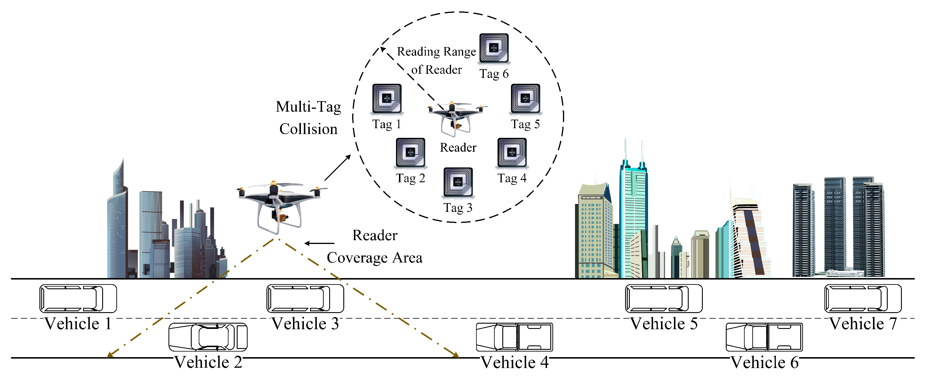
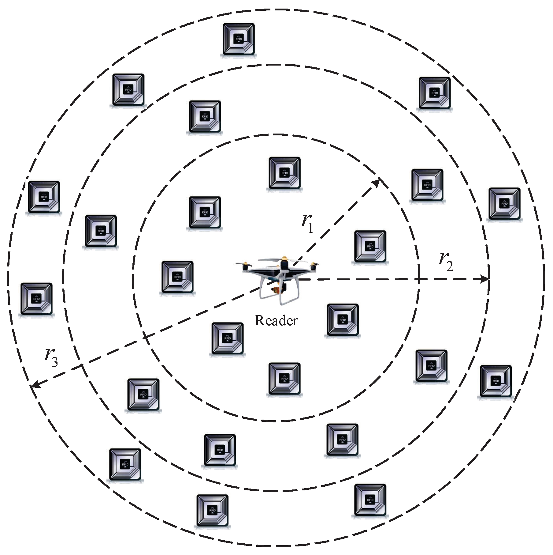
The proposed RFID-integrated framework in UAV-aided VANETs is shown in Figure 1, which consists of a UAV and multiple vehicles. UHF passive tags are assembled on each vehicle. In addition, the reader is mounted on the UAV and can identify vehicular tags with RFID technology [15]. When readers mounted on UAVs intelligently detect road conditions, there will be a large number of tags in their reading range. These tags can assist drivers to make better use of ITS.
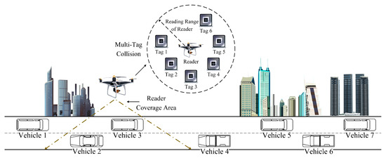
Figure 1.
A RFID-integrated framework in UAV-aided VANETs.
In practical applications, as there are a large number of tags in the network, there will be internal interference between tags, i.e., the tag collision problem [40]. Specifically, if there is only one tag in the reader’s coverage, the reader can identify it directly without collision. However, if there are two or more tags within the reader’s coverage, these tags will be detected in the same channel simultaneously, resulting in a collision between tags [41]. When tag collision occurs, the reader cannot correctly identify each tag, which will affect the QoS of each vehicle.
2.2. Tags Collision Model
In this paper, the reader mounted on a UAV adopts the time division multiple access (TDMA)-based aloha mechanism to identify tags [42]. It is assumed that there are T tags to be identified within the reader’s coverage. We denote the ID set of tags as . The initial frame length set by the reader is F, i.e., the number of time slots in a frame is F. We denote the ID set of frames as . Since the tag randomly selects time slot for responding, the probability of each time slot being selected is equal with the probability . In addition, the distribution of tags in a frame obeys a binomial distribution [14]. Therefore, the probability that n tags select the same time slot f () is
As shown in Figure 2, at the end of a frame identification, the reader can detect and count the response of tags in each time slot, and divide it into the following three cases:
Case 1: Only one tag is transmitted in the time slot f, which is called the successful slot, and the probability is represented as .
Case 2: No tag is transmitted in the time slot f, which is called the idle slot, and the probability is represented as .
Case 3: At least two tags are transmitted in the time slot f, which is called the collision slot, and the probability is represented as .
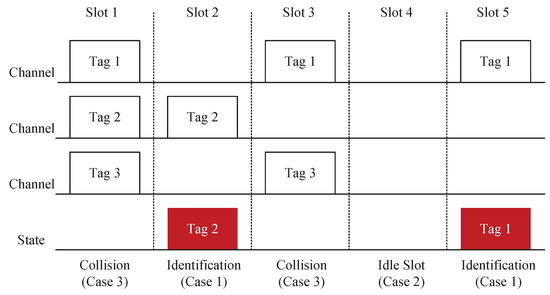
Figure 2.
A sample illustration of tag collision.
Figure 2.
A sample illustration of tag collision.

Therefore, we have
and
According to the above analysis, the number of successful slots , the number of idle slots , and the number of collision slots can be, respectively, expressed as
and
Therefore, the throughput is derived as
When , we can find the maximum throughput . We can prove that the first-order derivative of throughput with respect to T is
Let , and we can obtain
When the number of tags is large enough, we perform Taylor expansion on Equation (10), which can be expressed as
According to Equations (9)–(11), the maximum throughput can be calculated as
Based on the above analysis about tag identification procedure, it is clear that the maximum throughput with single-frequency tags is 36.7%, which cannot satisfy the demand for dense RFID-integrated VANETs. Motivated by this problem, the objective of this research is to investigate the optimal tag anti-collision scheme for large-scale passive RFID-integrated VANETs, i.e., .
3. Tag Anti-Collision Scheme
3.1. Multifrequency Tags Identification
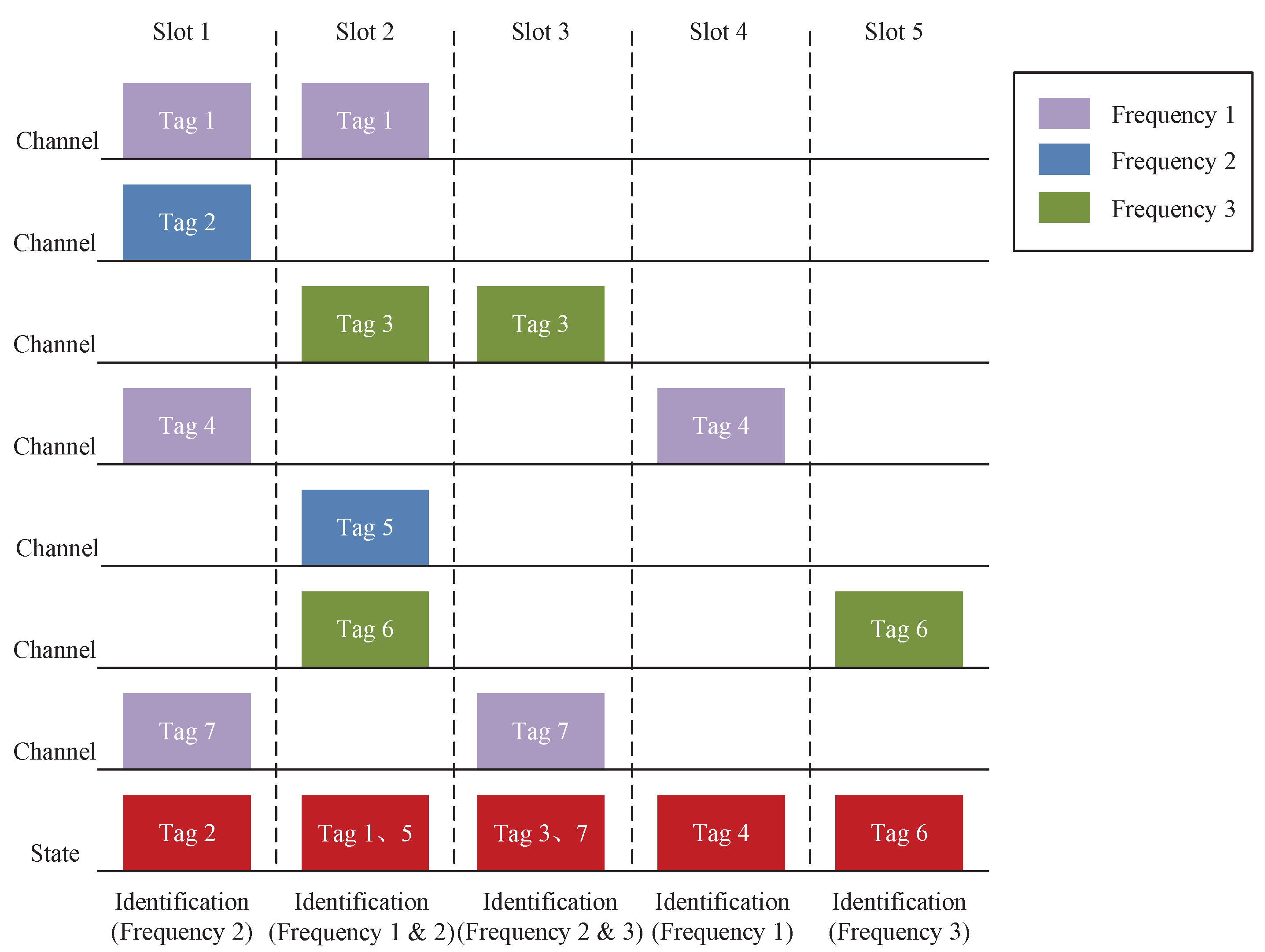
In RFID-integrated UAV-aided VANETs, we utilize the multifrequency tag identification method for VANETs, which is shown in Figure 3. Specifically, Figure 3 illustrates a three-frequency tag identification method. In the same time slot, the reader can identify multiple tags of different frequencies. Collisions occur only when tags with the same frequency are transmitted in the same time slot. For example, the reader can identify tag 2 in slot 1. The reason is that tag 2 has a different frequency than the other tags. Similarly, since tags 1 and 5 are different in frequency from the other tags, the reader can identify tag 1 and tag 5 in slot 2.
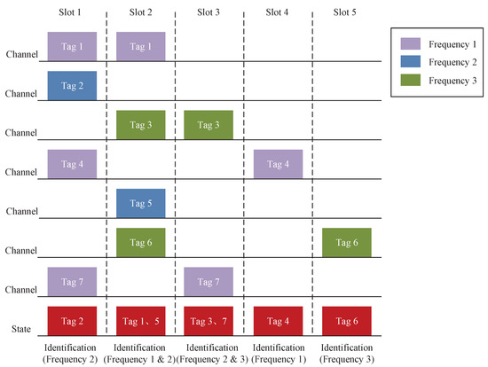
Figure 3.
A sample illustration of the multifrequency tag identification method.
Therefore, Equation (5) can be rewritten as
where represents the number of successful slots in the multifrequency tag identification method; represents the number of time slots, where k tags send messages simultaneously and i tags can be successfully identified () as
where M represents the number of frequencies. We denote the ID set of frequencies as , . Based on the analysis above, the throughput in the multifrequency tag identification method can be calculated as
3.2. Tags Grouping
Due to the limitations of RFID technology hardware conditions, the frame length cannot increase without limit, and the maximum frame length is generally 256 [43]. Therefore, when the number of tags to be identified exceeds this value, i.e., , it is impossible to improve the throughput by dynamically adjusting the frame length. Facing this challenge, the tags that are waiting to be identified need to be grouped, so as to reduce the number of collision slots within the groups and improve the identification efficiency.
We group the tags by the received power. The relationship between the reader transmitting power P and read–write radius R can be expressed as
where represents the wavelength of the emitted electro-magnetic wave, represents the gain of the reader, represents the gain of the tag t, and represents the electromagnetic power that the tag t extracts from the reader.
Based on Equation (16), we devise a tag grouping method based on adaptive power control for the reader, which can dynamically match the optimal frame length as shown in Figure 4. In the proposed method, the reader can dynamically adjust the transmitting power P to change the read–write radius R. Then, we group the tags based on their locations. The read–write radius of the reader can be gradually increased from small to large, until the maximum read–write radius, and all tags are identified in turn. In this stage, it is assumed that there are C groups in the network. We define the read–write radius ID of each group as , . Thus, the read–write range of the reader in each group is given by
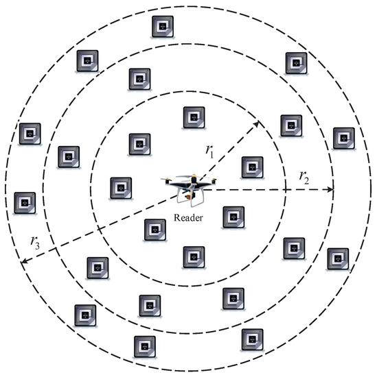
Figure 4.
The tag grouping method based on the adaptive power control for the reader.
Then, by adjusting the transmitting power of the reader, the read–write range is determined as
We, respectively, define and as the throughputs of the l-th group and l+1-th group, which can be calculated as
and
When , the l-th group and l+1-th group have the same throughput. Therefore, we have
According to Equation (21), we can group the tags.
3.3. Tags Estimation
According to the tag collision model, we can observe that the throughput in the proposed multifrequency tag identification method is dependent on the number of tags to be identified. In RFID-integrated UAV-aided VANETs, since the number of tags waiting to be identified is unknown, the reader needs to obtain the number of tags to be identified through a tag estimation method. As shown in Table 2, there are several methods for tag estimation [44].
Table 2.
Tag estimation methods.
The above methods have improved the accuracy of tag estimation. Nevertheless, there are still some estimation errors. Therefore, in order to improve the estimation accuracy, we introduce a tag estimation method using optimal weight.
The estimation error can be derived as
where represents the actual number of tags to be identified, represents the estimated value of the i-th tag estimation method, represents the estimation error of i-th tag estimation method, and I represents the number of tag estimation methods.
The estimated value of tags can be calculated as
where represents the weight of the i-th tag estimation method.
The mean square error of our introduced tag estimation method is
where represents the standard deviation of our introduced tag estimation method.
According to the Lagrangian multiplier method, we can derive the optimal weight as
Therefore, Equation (23) can be equivalently rewritten as
3.4. Flowchart of Our Scheme
The detailed flowchart of the proposed tag anti-collision scheme is shown in Figure 5. In detail, the reader mounted on the UAV first identifies the tags according to Equation (14). Then, the reader records the number of successful slots , the number of idle slots , and the number of collision slots . Afterward, according to , , and , the reader estimates the number of tags to be identified. Based on this, the reader determines whether the tags need to be grouped. If the tags need to be grouped, the power of the reader should be adjusted according to Equations (16)–(18), based on which, Equation (14) is used to identify the tags of each group. Repeat this process until all tags are identified.
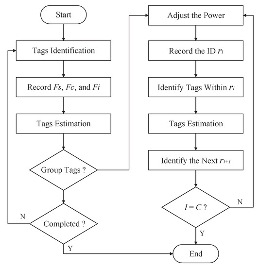
Figure 5.
Flowchart for the proposed tag anti-collision scheme.
3.5. Security Performance Analysis
3.5.1. Security Capacity
In RFID-integrated UAV-aided VANETs, due to the broadcast characteristics of wireless communication between reader and tags, the privacy transmission of tags is challenged by eavesdropping [45]. Therefore, this paper analyzes the security capacity of the proposed network framework.
According to the Slivnyak theorem [46], the signal to interference plus noise ratio () between the reader and the tag t can be expressed as
where represents the small scale fading between the reader and the tag t, , represents the distance between the reader and the tag t, represents the path loss factor, v represents the other tag v, represents the small scale fading between the reader and the tag v, , represents the transmitting power of the tag v, represents the distance between the reader and the tag v, and represents the noise power received by the reader. In this paper, we consider the most dangerous eavesdropper e, whose can be expressed as
where represents the eavesdropper set, , represents the small scale fading between the reader and the eavesdropper e, , represents the distance between the reader and the eavesdropper e, represents the small scale fading between the tag v and the eavesdropper e, , represents the distance between the tag v and the eavesdropper e, and represents the noise power received by the eavesdropper e. According to the above analysis, the security capacity of our proposed network framework is
3.5.2. Security Outage Probability (SOP)
When of the reader is less than the secure threshold R, it can be considered that the communication at this time is not secure enough, resulting in a security outage [47]. The SOP between the reader and the tag t can be expressed as
where represents the distribution function of of eavesdropper e, and represents the average transmission speed. Since is difficult to calculate directly, according to Jensen’s inequality, we can obtain
We define as the minimum value of , which can be expressed as
Therefore, the distribution function of of eavesdropper e is given by
4. Simulation Experiments
4.1. Simulation Parameters
In this section, we evaluate the performance of the proposed tag anti-collision scheme via simulations. In our simulations, we explore the effects of the number of frequencies and the frame length on the throughput. In addition, we compare the proposed tag anti-collision scheme with three schemes, namely, the Prakash et al. scheme [31], the Bae et al. scheme [32], and the Jiang et al. scheme [42]. The detailed simulation parameters are summarized in Table 3 [14,43].
Table 3.
Simulation parameters.
4.2. Simulation Results
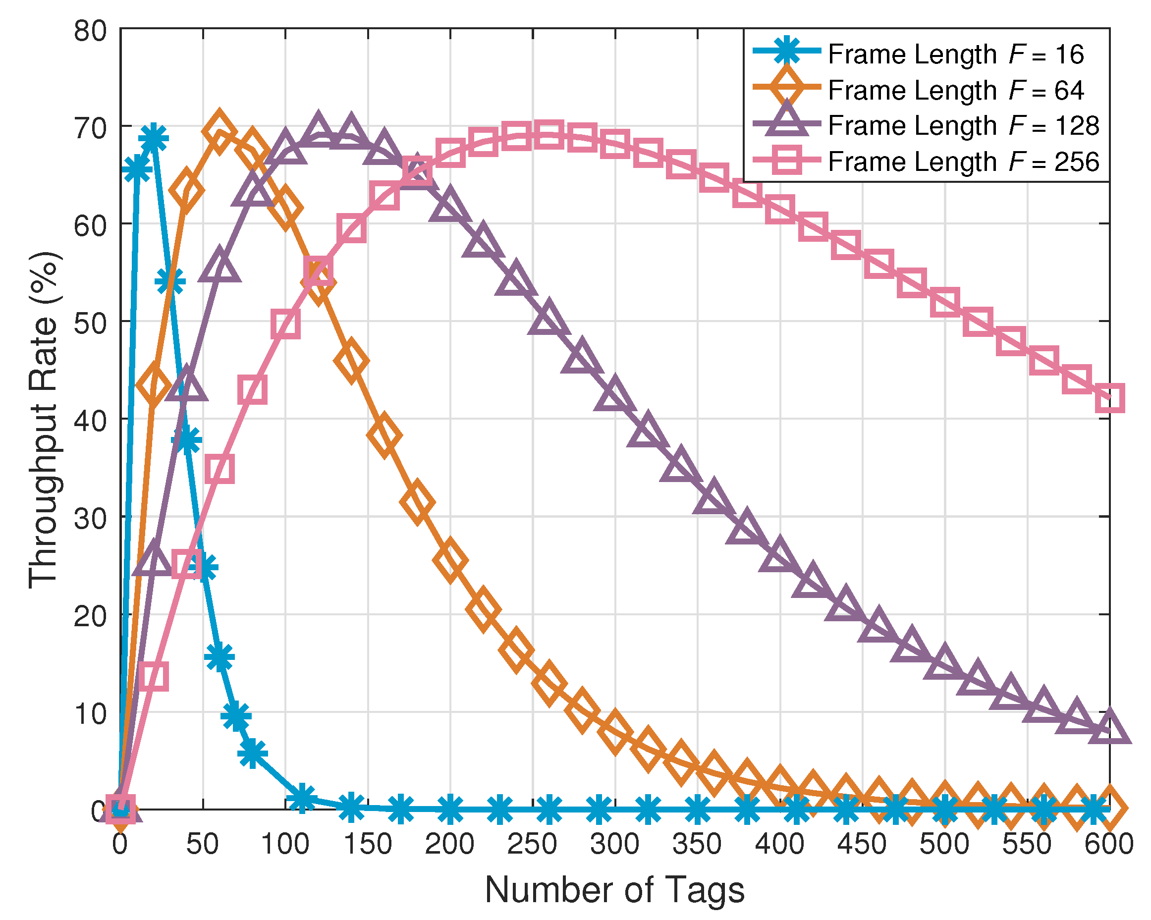
Figure 6 shows the comparison of the throughput with respect to the number of tags under the different frame lengths. It can be seen from this figure that, when the frame length is fixed, the throughput of our proposed tag anti-collision scheme increases at first and then decreases. Specifically, the throughput of the network reaches its maximum value when the frame length equals the number of tags. When the number of tags to be identified exceeds the frame length, the throughput drops sharply. These simulation results are consistent with Equation (21) and prove that we need to estimate the tags waiting to be identified and adjust the transmitting power of the reader adaptively to group the tags. In the light of the analyses above, we adopt the devised tag grouping method based on adaptive power control to group the tags waiting to be identified, and the results are shown in Table 4.
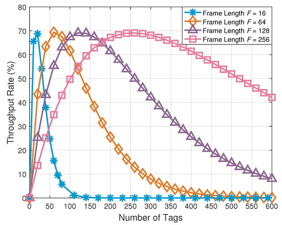
Figure 6.
Comparison of the throughput rate with respect to the number of tags under the different frame lengths.
Table 4.
Tag grouping results.
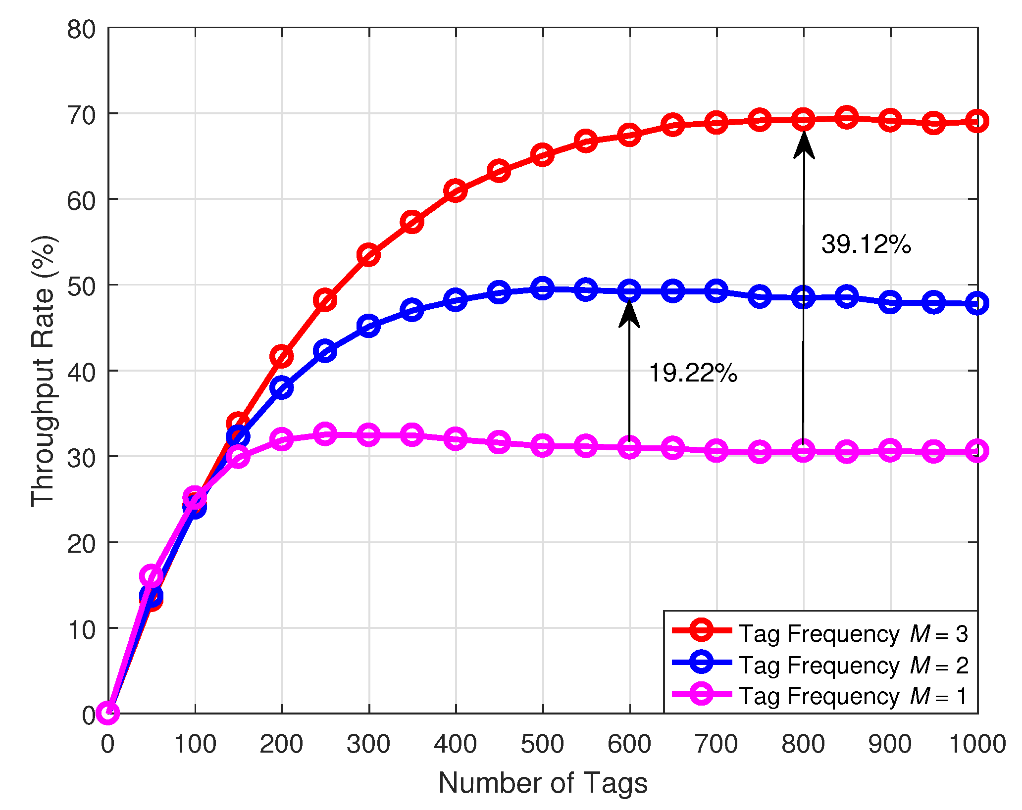
Figure 7 illustrates the comparison of the throughput with respect to the number of tags under the different number of frequencies. The simulation results indicate that the proposed multifrequency tag identification method can significantly improve the throughput and reduce the collision probability. Compared with the conventional single-frequency tag identification scheme, the dual-frequency tag identification scheme can increase the throughput by 19.22%, and the three-frequency tag identification scheme can increase the throughput by 39.12%. This phenomenon can be explained through Equation (15).
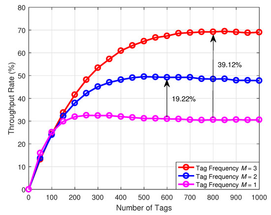
Figure 7.
Comparison of the throughput rate with respect to the number of tags under the different number of frequencies.
More specifically, the probability of the tags being identified monotonically increases with the number of frequencies. However, since the number of frequencies of tags is limited by the cost and the complexity of the reader, the number of frequencies cannot be excessive. In addition, when the number of tags is less than 150, the throughput of the three schemes is similar. In effect, as the number of tags becomes smaller, the probability of tag collision drops. In order to reduce the cost, we can use the single-frequency tag identification scheme in this case. In a tag intensive scenario, the multifrequency tag identification method can be utilized to identify the tags.
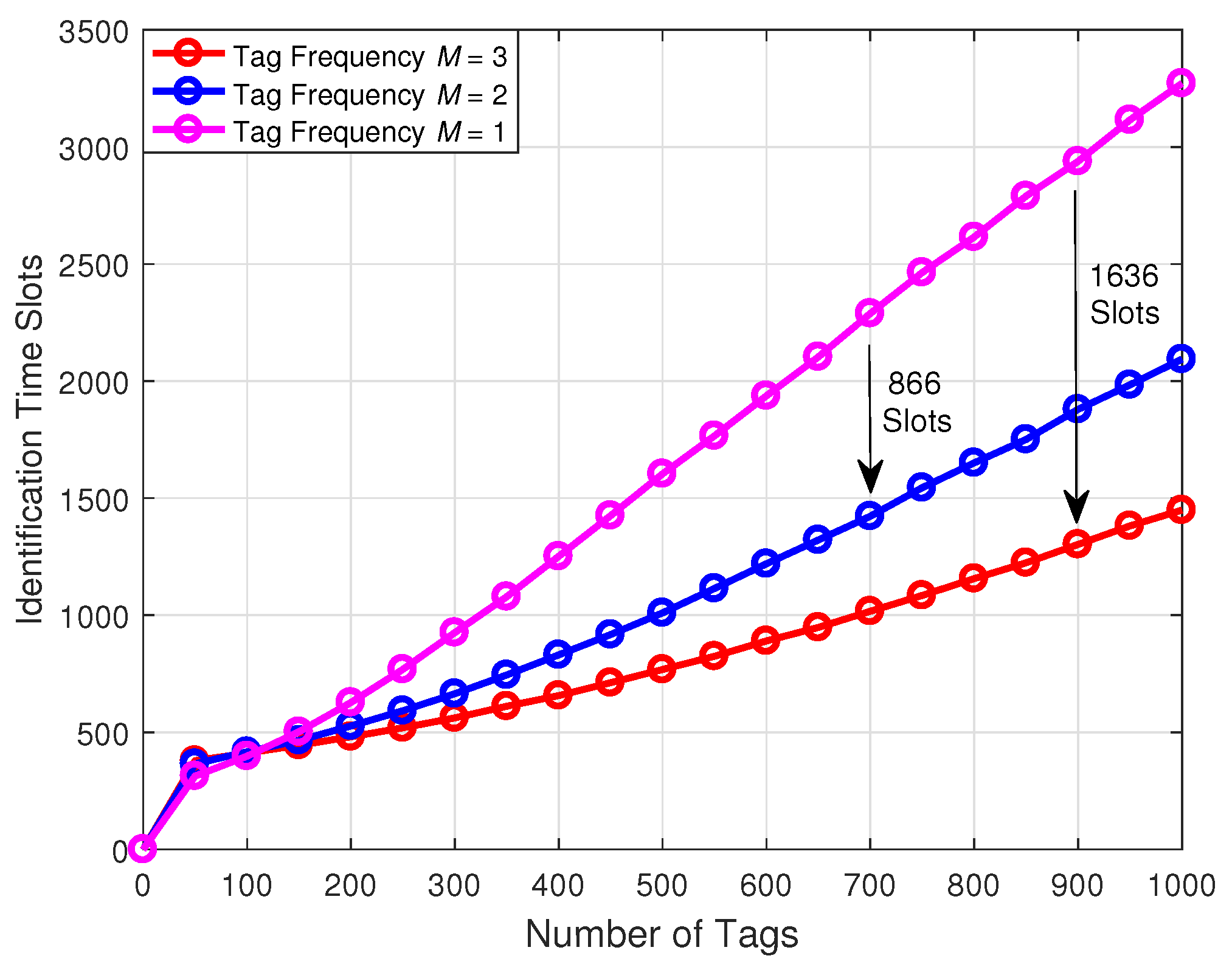
Figure 8 demonstrates a comparison of the identification time slots with respect to the number of tags under the different number of frequencies. From this figure, we can observe that, when the number of tags identified by the reader is the same, the identification time slots decrease with the increase of frequency. Specifically, taking 900 tags identified by the reader as an example, the three-frequency tag identification scheme can reduce 1636 identification time slots compared with the conventional single-frequency tag identification scheme.
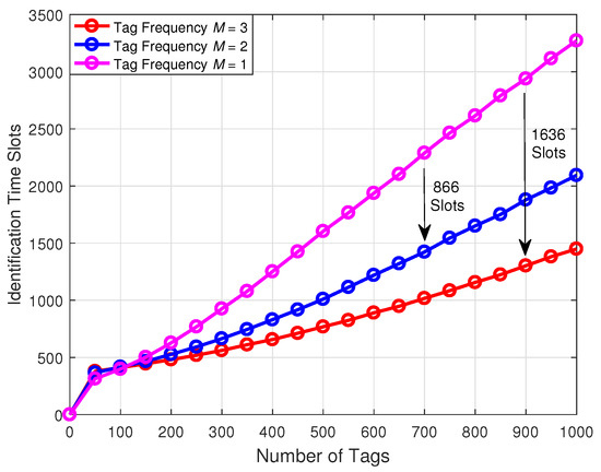
Figure 8.
Comparison of the identification time slots with respect to the number of tags under the different number of frequencies.
Moreover, we can find that, compared with the dual-frequency tag identification scheme, the single-frequency tag identification scheme needs to add 866 identification time slots to identify 700 tags. Furthermore, when the number of tags is less than 50, the identification time slots of three schemes all rise rapidly. This is because our initial frame length is set to 256, and there are many idle time slots causing the number of time slots to increase.
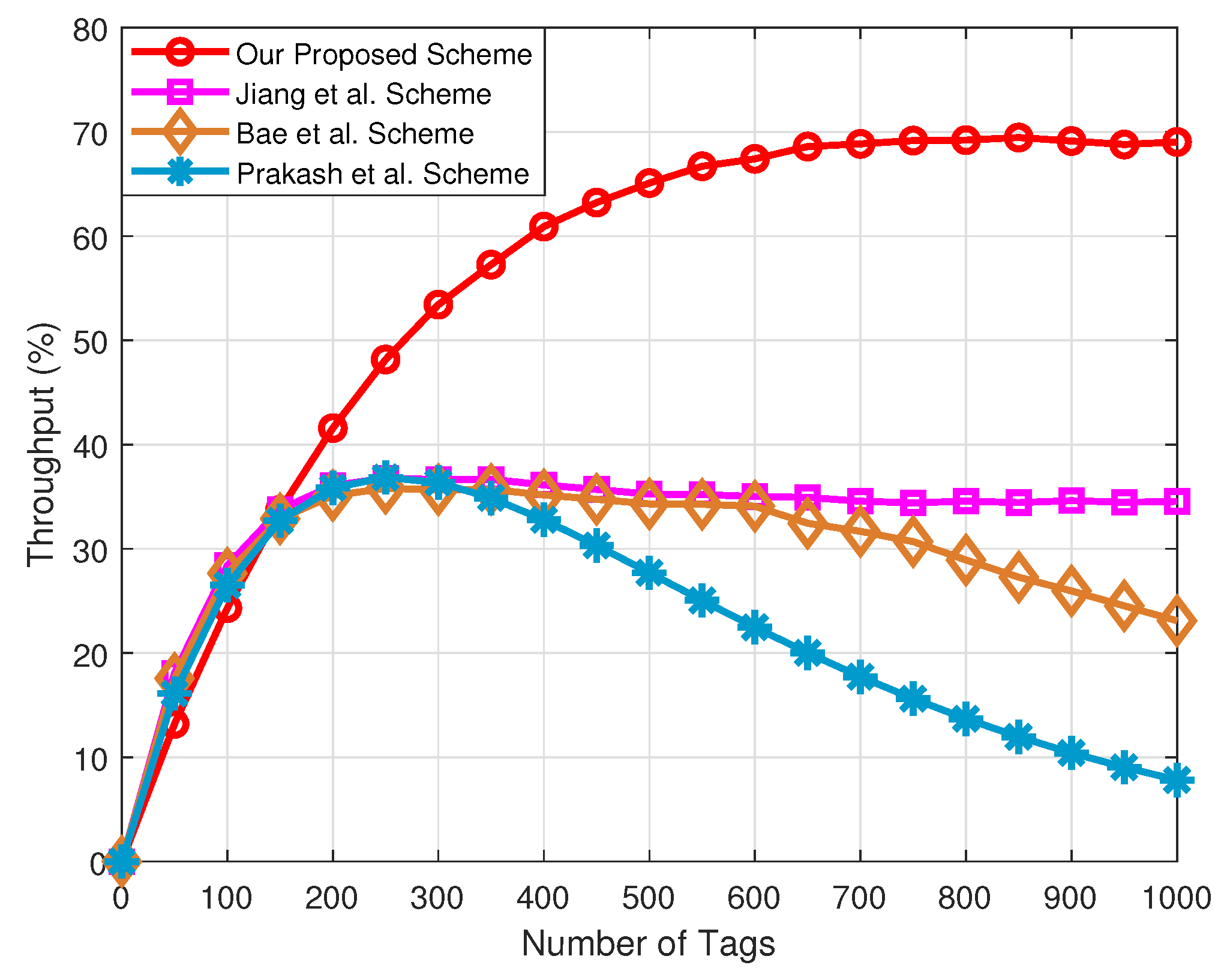
Figure 9 presents the comparison of the throughput with respect to the number of tags under the different schemes. In this figure, we adopt Equation (15) to calculate the throughput rate, and other schemes adopt Equation (8) to calculate the throughput rate. Clearly, in terms of the throughput, our proposed tag anti-collision scheme has obvious advantages over the other three schemes, especially for the Prakash et al. scheme. This is due to the use of fixed frame lengths in the Prakash et al. scheme. Therefore, when the number of tags is larger than the optimal frame length, the collision time slots increase, and the reader cannot identify tags in VANETs.
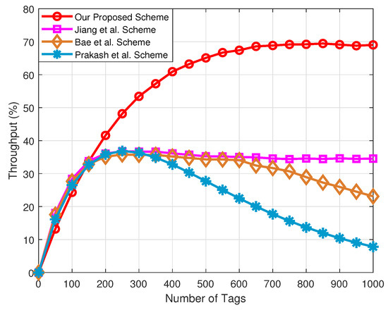
Figure 9.
Comparison of the throughput rate with respect to the number of tags under the different schemes.
Secondly, although the Bae et al. scheme estimates the tags waiting to be identified, it does not take into account the grouping of tags, and thus the throughput will be reduced in large-scale tag-intensive scenarios. Additionally, since the multifrequency tag identification method is used to the proposed network framework, the throughput is significantly improved compared with the Jiang et al. scheme based on a single frequency.
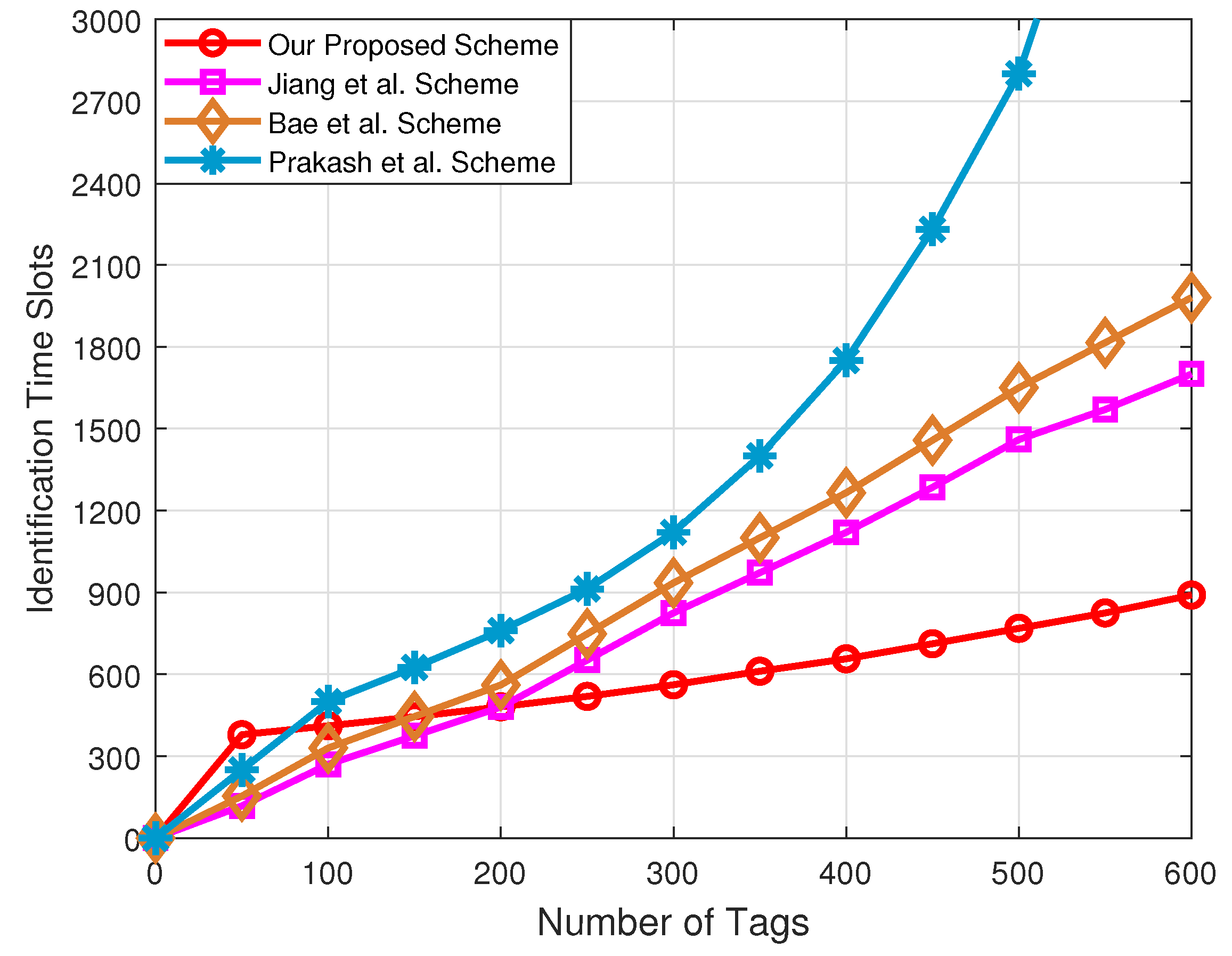
Figure 10 plots the comparison of the identification time slots with respect to the number of tags under the different schemes. Since the frame length of the Prakash et al. scheme is fixed, the number of identification time slots required increases exponentially as the number of tags increases. The number of identification time slots required by the Jiang et al. and Bae et al. schemes is similar, because the frame length of both schemes can only grow to the maximum, which is equal to 256. For the Jiang et al. scheme, the number of identification time slots required is slightly lower than for Bae et al. scheme. The reason is that the Jiang et al. scheme can use a tag grouping method to reduce the collision slots.
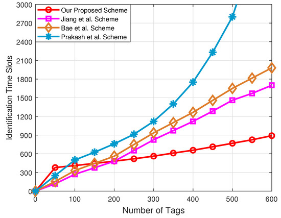
Figure 10.
Comparison of the identification time slots with respect to the number of tags under the different schemes.
In addition, we found that our proposed tag anti-collision scheme required the least number of identification time slots. This is because that our proposed tag anti-collision scheme can adaptively adjust the transmitting power of the reader to group tags according to the number of tags to be identified, and the frame length can be dynamically adjusted to ensure the maximum throughput in each group. Furthermore, the reader can use a multi-frequency tag for identification. As a consequence, more tags can be identified in the same time slot, which can reduce collision time slots.
5. Conclusions
In this paper, we integrated RFID technology into UAV-aided VANETs to provide reliable traffic-related services for vehicles, based on which, we investigated the tag anti-collision problem. First, we designed the multifrequency tag identification method to improve the throughput and reduce the collision time slots. Then, we devised a tag grouping method based on adaptive power control, which can make the reader dynamically match the optimal frame length. Moreover, exploiting the optimal weight, we introduce a tag estimation method, which can effectively ensure the maximum throughput in each group. Finally, the simulation results demonstrated that our proposed tag anti-collision scheme achieved significant performance gains in comparison with the other schemes.
In addition to the problems listed above, there are many research issues worthy of further investigation. In this paper, we were committed to the study of the tag anti-collision problem, and the reader anti-collision problem was ignored. More sophisticated analysis and experiments using UAV deployment, dynamic network topology, and realistic communication protocols will be valuable to fully understand our proposed network framework performance. Additionally, the performance of the proposed tag anti-collision scheme was evaluated via simulations; however, in practical applications, in addition to the internal interference between the tags, there can be complex electromagnetic interference from the environment. It would be much better to consider the influence of electromagnetic interference in a real environment.
As a future work, we plan to study the anti-collision scheme of combining reader collision and tag collision, based on which, we will take the influence of dynamic parameters into account. Further, the electromagnetic interference problem is also a practical factor worthy of further study. In the future, we will investigate RFID-integrated VANETs applications by jointly considering the tag anti-collision and electromagnetic interference. Nevertheless, the tag anti-collision scheme designed in this paper provides important insights and suggests a promising direction regarding RFID technology applications for UAV-aided VANETs.
Author Contributions
Y.H.: Conceptualization, Methodology, Software, Writing—Original Draft Preparation, and Visualization. D.W.: Conceptualization, Resources, Writing—Review and Editing, Supervision, Project Administration, and Funding Acquisition. F.H.: Conceptualization, and Writing—Review and Editing. Y.Z.: Software, and Formal Analysis. R.Z.: Conceptualization, Resources, Supervision, and Funding Acquisition. X.Y.: Resources and Funding Acquisition. All authors have read and agreed to the published version of the manuscript.
Funding
This work was supported in part by the Foundation of the Science, Technology, and Innovation Commission of Shenzhen Municipality under Grant JCYJ20190806160218174, in part by the National Natural Science Foundation of China under Grant 61901379, Grant 61941119, and Grant 61901366, in part by the National Key Research and Development Program of China under Grant 2020YFB1807003, in part by the open research fund of National Mobile Communications Research Laboratory, Southeast University under Grant 2020D04, in part by the State Administration of Science, Technology and Industry for National Defence Public Project: Satellite-based Broadband Data Access with Non-Fourier Transform under Grant HTK2020KL504016, in part by the Innovation Foundation for Doctor Dissertation of Northwestern Polytechnical University under Grant CX202037, and in part by the Program of China Scholarships Council under Grant 202006290166.
Institutional Review Board Statement
Not applicable.
Informed Consent Statement
Not applicable.
Data Availability Statement
Not applicable.
Conflicts of Interest
The authors declare no conflict of interest.
References
- Feroz, S.; Abu Dabous, S. UAV-Based Remote Sensing Applications for Bridge Condition Assessment. Remote Sens. 2021, 13, 1809. [Google Scholar] [CrossRef]
- Say, S.; Inata, H.; Liu, J.; Shimamoto, S. Priority-Based Data Gathering Framework in UAV-Assisted Wireless Sensor Networks. IEEE Sens. J. 2016, 16, 5785–5794. [Google Scholar] [CrossRef]
- Huang, F.; Zhang, Y.; Wang, Z.; Deng, X. A Novel Conflict Management Method Based on Uncertainty of Evidence and Reinforcement Learning for Multi-Sensor Information Fusion. Entropy 2021, 23, 1222. [Google Scholar] [CrossRef] [PubMed]
- Wang, D.; He, Y.; Yu, K.; Srivastava, G.; Nie, L.; Zhang, R. Delay Sensitive Secure NOMA Transmission for Hierarchical HAP-LAP Medical-care IoT Networks. IEEE Trans. Ind. Informat. 2021. to be published. [Google Scholar] [CrossRef]
- He, Y.; Zhai, D.; Jiang, Y.; Zhang, R. Relay Selection for UAV-assisted Urban Vehicular Ad Hoc Networks. IEEE Wirel. Commun. Lett. 2020, 9, 1379–1383. [Google Scholar] [CrossRef]
- Jobaer, S.; Zhang, Y.; Iqbal Hussain, M.A.; Ahmed, F. UAV-Assisted Hybrid Scheme for Urban Road Safety Based on VANETs. Electronics 2020, 9, 1499. [Google Scholar] [CrossRef]
- Aggarwal, S.; Kumar, N.; Tanwar, S. Blockchain-Envisioned UAV Communication Using 6G Networks: Open Issues, Use Cases, and Future Directions. IEEE Internet Things J. 2021, 8, 5416–5441. [Google Scholar] [CrossRef]
- Afrashteh, M.; Babaie, S. A Route Segmented Broadcast Protocol Based on RFID for Emergency Message Dissemination in Vehicular Ad-Hoc Networks. IEEE Trans. Veh. Technol. 2020, 69, 16017–16026. [Google Scholar] [CrossRef]
- Saxl, G.; Görtschacher, L.; Ussmueller, T.; Grosinger, J. Software-Defined RFID Readers: Wireless Reader Testbeds Exploiting Software-Defined Radios for Enhancements in UHF RFID Systems. IEEE Microw. Mag. 2021, 22, 46–56. [Google Scholar] [CrossRef]
- Zhang, W.; Lin, B.; Gao, C.; Yan, Q.; Li, S.; Li, W. Optimal Placement in RFID-Integrated VANETs for Intelligent Transportation System. In Proceedings of the 2018 IEEE International Conference on RFID Technology & Application (RFID-TA), Macao, China, 26–28 September 2018; pp. 1–6. [Google Scholar]
- Buffi, A.; Nepa, P.; Cioni, R. SARFID on drone: Drone-based UHF-RFID tag localization. In Proceedings of the 2017 IEEE International Conference on RFID Technology & Application (RFID-TA), Warsaw, Poland, 20–22 September 2017; pp. 40–44. [Google Scholar]
- Longhi, M.; Marrocco, G. Flying Sensors: Merging Nano-UAV with Radiofrequency Identification. In Proceedings of the 2017 IEEE International Conference on RFID Technology & Application (RFID-TA), Warsaw, Poland, 20–22 September 2017; pp. 164–168. [Google Scholar]
- Greco, G.; Lucianaz, C.; Bertoldo, S.; Allegretti, M. A Solution for Monitoring Operations in Harsh Environment: A RFID Reader for Small UAV. In Proceedings of the 2015 International Conference on Electromagnetics in Advanced Applications (ICEAA), Turin, Italy, 7–11 September 2015; pp. 859–862. [Google Scholar]
- He, Y.; Zhang, R.; Li, B.; Wang, D. An Anti-Collision Protocol Based on UAV for Internet of Things. In Proceedings of the IEEE 11th International Conference on Wireless Communications and Signal Processing (WCSP), Xi’an, China, 23–25 October 2019; pp. 1–6. [Google Scholar]
- Buffi, A.; Motroni, A.; Nepa, P.; Tellini, B.; Cioni, R. A SAR-Based Measurement Method for Passive-Tag Positioning with a Flying UHF-RFID Reader. IEEE Trans. Instrum. Meas. 2019, 68, 845–853. [Google Scholar] [CrossRef]
- Hrúz, M.; Bugaj, M.; Novák, A.; Kandera, B.; Badánik, B. The Use of UAV with Infrared Camera and RFID for Airframe Condition Monitoring. Appl. Sci. 2021, 11, 3737. [Google Scholar] [CrossRef]
- Won, D.; Park, M.; Chi, S. Construction Resource Localization Based on UAV-RFID Platform Using Machine Learning Algorithm. In Proceedings of the 2018 IEEE International Conference on Industrial Engineering and Engineering Management (IEEM), Bangkok, Thailand, 16–19 December 2018; pp. 1086–1090. [Google Scholar]
- Zhang, J.; Yu, Z.; Mao, S.; Periaswamy, S.C.G.; Patton, J.; Xia, X. IADRL: Imitation Augmented Deep Reinforcement Learning Enabled UGV-UAV Coalition for Tasking in Complex Environments. IEEE Access 2020, 8, 102335–102347. [Google Scholar] [CrossRef]
- Orgeira-Crespo, P.; Ulloa, C.; Rey-Gonzalez, G.; Pérez García, J.A. Methodology for Indoor Positioning and Landing of an Unmanned Aerial Vehicle in a Smart Manufacturing Plant for Light Part Delivery. Electronics 2020, 9, 1680. [Google Scholar] [CrossRef]
- Won, D.; Chi, S.; Park, M. UAV-RFID Integration for Construction Resource Localization. KSCE J. Civ. Eng. 2020, 24, 1683–1695. [Google Scholar] [CrossRef]
- Li, C.; Tanghe, E.; Plets, D.; Suanet, P.; Hoebeke, J.; Poorter, E.D.; Joseph, W. ReLoc: Hybrid RSSI- and Phase-Based Relative UHF-RFID Tag Localization With COTS Devices. IEEE Trans. Instrum. Meas. 2020, 69, 8613–8627. [Google Scholar] [CrossRef]
- Rahman, M.M.; McDermid, G.J.; Strack, M.; Lovitt, J. A New Method to Map Groundwater Table in Peatlands Using Unmanned Aerial Vehicles. Remote Sens. 2017, 9, 1057. [Google Scholar] [CrossRef] [Green Version]
- Casati, G.; Longhi, M.; Latini, D.; Carbone, F.; Amendola, S.; Frate, F.D.; Schiavon, G.; Marrocco, G. The Interrogation Footprint of RFID-UAV: Electromagnetic Modeling and Experimentations. IEEE J. Radio Freq. Identificat. 2017, 1, 155–162. [Google Scholar] [CrossRef]
- Tan, X.; Wang, H.; Fu, L.; Wang, J.; Min, H.; Engels, D.W. Collision Detection and Signal Recovery for UHF RFID Systems. IEEE Trans. Autom. Sci. Eng. 2018, 15, 239–250. [Google Scholar]
- Samsami, M.M.; Yasrebi, N. Novel RFID Anti-Collision Algorithm Based on the Monte-Carlo Query Tree Search. Wirel. Netw. 2021, 27, 621–634. [Google Scholar] [CrossRef]
- Jia, X.; Bolic, M.; Feng, Y.; Gu, Y. An Efficient Dynamic Anti-Collision Protocol for Mobile RFID Tags Identification. IEEE Commun. Lett. 2019, 23, 620–623. [Google Scholar] [CrossRef]
- Gao, Y.; Gao, X.; Yang, X.; Liu, J.; Chen, G. An Efficient Ring-Based Metadata Management Policy for Large-Scale Distributed File Systems. IEEE Trans. Parallel Distrib. Syst. 2019, 30, 1962–1974. [Google Scholar] [CrossRef]
- Huang, Z.; Xu, R.; Chu, C.; Li, Z.; Qiu, Y.; Li, J.; Ma, Y.; Wen, G. A Novel Cross Layer Anti-Collision Algorithm for Slotted ALOHA-Based UHF RFID Systems. IEEE Access 2019, 7, 36207–36217. [Google Scholar] [CrossRef]
- Benedetti, D.; Maselli, G.; Petrioli, C.; Piva, M. The Impact of External Interference on RFID Anti-Collision Protocols. IEEE Netw. Lett. 2019, 1, 76–79. [Google Scholar] [CrossRef]
- Pakkathillam, J.K.; Kanagasabai, M.; Alsath, M.G.N. Compact Multiservice UHF RFID Reader Antenna for Near-Field and Far-Field Operations. IEEE Antennas Wirel. Propag. Lett. 2017, 16, 149–152. [Google Scholar] [CrossRef]
- Prakash, A.; Anand, R.; Chandra, B.M. Forward Search Approach Using Power Search Algorithm (FSA-PSA) to Solve Dynamic Economic Load Dispatch problems. In Proceedings of the 2019 5th International Conference on Advanced Computing & Communication Systems (ICACCS), Coimbatore, India, 15–16 March 2019; pp. 1139–1142. [Google Scholar]
- Bae, Y.H. Modeling Timely-Delivery Ratio of Slotted Aloha With Energy Harvesting. IEEE Commun. Lett. 2017, 21, 1823–1826. [Google Scholar] [CrossRef]
- Khalil, G.; Doss, R.; Chowdhury, M. A New Secure RFID Anti-Counterfeiting and Anti-Theft Scheme for Merchandise. J. Sens. Actuator Netw. 2020, 9, 16. [Google Scholar] [CrossRef] [Green Version]
- Liu, H.; Ning, H.; Zhang, Y.; He, D.; Xiong, Q.; Yang, L.T. Grouping-proofs-based Authentication Protocol for Distributed RFID Systems. IEEE Trans. Parallel Distrib. Syst. 2013, 24, 1321–1330. [Google Scholar] [CrossRef]
- Sun, D.; Mu, Y. Security of Grouping-proof Authentication Protocol for Distributed RFID Systems. IEEE Wirel. Commun. Lett. 2018, 7, 254–257. [Google Scholar] [CrossRef]
- Hosseinzadeh, M.; Lansky, J.; Rahmani, A.M.; Trinh, C.; Safkhani, M.; Bagheri, N. Huynh, B. A New Strong Adversary Model for RFID Authentication Protocols. IEEE Access 2020, 8, 125029–125045. [Google Scholar] [CrossRef]
- He, Y.; Zhai, D.; Huang, F.; Wang, D.; Tang, X.; Zhang, R. Joint Task Offloading, Resource Allocation, and Security Assurance for Mobile Edge Computing-Enabled UAV-Assisted VANETs. Remote Sens. 2021, 13, 1547. [Google Scholar] [CrossRef]
- Fan, K.; Jiang, W.; Li, H.; Yang, Y. Lightweight RFID Protocol for Medical Privacy Protection in IoT. IEEE Trans. Ind. Informat. 2018, 14, 1656–1665. [Google Scholar] [CrossRef]
- Sun, H.; Ting, W. ISO/IEC WD 29167–6 Information Technology—Automatic Identification and Data Caputre Techniques—Part 6: Air Interface for Security Services and File Management for RFID at 860–960 MHz; Internation Organization for Standardization: Geneva, Switzerland, 2010. [Google Scholar]
- Arjona, L.; Landaluce, H.; Perallos, A.; Onieva, E. Dynamic Frame Update Policy for UHF RFID Sensor Tag Collisions. Sensors 2020, 20, 2696. [Google Scholar] [CrossRef] [PubMed]
- Chen, Y.H.; Chen, Y.A.; Huang, S.R. A Mobility Aware Binary Tree Algorithm to Resolve RFID Jam and Bottleneck Problems in a Next Generation Specimen Management System. Micromachines 2020, 11, 755. [Google Scholar] [CrossRef] [PubMed]
- Jiang, Z.; Li, B.; Yang, M.; Yan, Z. LC-DFSA: Low Complexity Dynamic Frame Slotted Aloha Anti-Collision Algorithm for RFID System. Sensors 2020, 20, 228. [Google Scholar] [CrossRef] [PubMed] [Green Version]
- Jiang, Y.; Zhang, R.; Cheng, W.; Li, B. A Tag Distribution Distance Based Collision Avoidance Algorithm in RFID Systems. J. Northwestern Polytech. Univ. 2016, 34, 250–255. [Google Scholar]
- Su, J.; Sheng, Z.; Liu, A.X.; Han, Y.; Chen, Y. A Group-Based Binary Splitting Algorithm for UHF RFID Anti-Collision Systems. IEEE Trans. Commun. 2020, 68, 998–1012. [Google Scholar] [CrossRef] [Green Version]
- Wang, D.; Zhou, F.; Leung, V.C.M. Primary Privacy Preserving With Joint Wireless Power and Information Transfer for Cognitive Radio Networks. IEEE Trans. Cognit. Commun. Netw. 2020, 6, 683–693. [Google Scholar] [CrossRef]
- Sheng, J.; Fan, Y.; Xia, M. Physical Layer Security Performance Analysis for Wireless Sensor Network. Comput. Eng. Appl. 2021, 57, 91–95. [Google Scholar]
- Wang, D.; Ren, P.; Cheng, J.; Wang, Y. Achieving Full Secrecy Rate With Energy-Efficient Transmission Control. IEEE Trans. Commun. 2017, 65, 5386–5400. [Google Scholar] [CrossRef]

Publisher’s Note: MDPI stays neutral with regard to jurisdictional claims in published maps and institutional affiliations. |
© 2021 by the authors. Licensee MDPI, Basel, Switzerland. This article is an open access article distributed under the terms and conditions of the Creative Commons Attribution (CC BY) license (https://creativecommons.org/licenses/by/4.0/).