Technical Note

Underwater Communication Using UAVs to Realize High-Speed AUV Deployment

1
Institute of Industrial Science, University of Tokyo, 4-6-1, Komaba, Meguro-ku, Tokyo 153-8505, Japan
2
School of Science and Technology, Meiji University, 1-1-1, Higashi-Mita, Tama-ku, Kawasaki, Kanagawa 214-8571, Japan
*
Author to whom correspondence should be addressed.
Remote Sens. 2021, 13(20), 4173; https://doi.org/10.3390/rs13204173
Submission received: 21 September 2021 / Revised: 14 October 2021 / Accepted: 14 October 2021 / Published: 18 October 2021
(This article belongs to the Special Issue Remote Sensing Technology for New Ocean and Seafloor Monitoring)

Abstract

:
To monitor ocean and seafloor properties in detail, sensors are generally installed on autonomous underwater vehicles (AUVs). An AUV cannot accurately determine its absolute position and needs to communicate with a sea-surface vehicle. However, sea-surface vehicles cannot perform high-speed observations with high efficiency due to their low mobility and high labor and equipment costs, e.g., vessel charter charges, operator restraint time on the sea surface during observations, etc. From this perspective, unmanned aerial vehicles (UAVs) have potential as the next-generation communication platform. In this study, we conducted a demonstration experiment to use UAV as a sea-surface base for underwater communication with an AUV. We investigated the capability of a UAV to land on the sea surface, drift like a buoy to receive underwater data, and finally lift off to return to its base. The experimental results suggest that UAVs provide suitable communication performance for research near the shore in terms of robust hovering control, stability against sway, and operation speed. To carry out more complicated work (such as transportation) of UAVs, further research in areas such as weight reduction is required.

1. Introduction

Autonomous underwater vehicles (AUVs) have been used for oceanographic surveys because of their ability to get close to the seafloor and obtain high-resolution seafloor images and terrain information. A method for estimating unknown currents has been studied to ensure a stable underwater observation of AUVs [1]. However, AUVs cannot directly acquire global navigation satellite system (GNSS) signals due to the strong attenuation of radio waves in water. Therefore, it is necessary to deploy base stations, such as ships, buoys, and autonomous vessels, on the sea surface [2,3,4,5]. However, it is not easy for sea-surface systems to follow AUVs because they drift due to disturbances such as waves and wind. Additionally, surface vehicles are constrained by sea-surface conditions, so their freedom of movement and speed are low.
For these reasons, the next generation of navigation/communication base stations on the sea surface needs to have efficient, high-speed positioning, in addition to stability. Unmanned aerial vehicles (UAVs) are good candidates for sea-surface stations. Especially near the shore, where small AUVs are used, multirotor-type UAVs have very high mobility (although fixed-wing UAVs do not). UAVs with high movement speed (about 50 km/h or more) and high-performance robust hovering control (i.e., not affected by ocean currents and other perturbations) can be used for communication with underwater exploration devices such as AUVs. An additional advantage is that they produce no underwater noise compared with sea-surface vessels.
In recent years, UAVs have been developed not only for onshore surveying but also for underwater surveying, imaging, and observation [6]. Floating UAVs are also being developed, but are primarily intended for photogenic and chemical surveys in calm environments such as lakes [7]. They can also be used as observation platforms that have lower manufacturing and operating costs and superior mobility [8,9]. In this study, we examined the potential use of UAVs as ”self-propelled buoys“ for ocean surveys (sea-surface observation and acoustic sensing).
Figure 1 shows the assumed use cases in which UAVs serve as sea-surface bases for underwater explorations. Figure 1a,b shows sonar-equipped UAVs for communication with an AUV. The UAV can hover above the sea surface with a suspended sonar device, or the device can be mounted on the UAV itself, in which the UAV lands on the sea surface. It is also possible to connect an underwater exploration device directly to the UAV and carry out surveys using only the UAV sea-surface base (Figure 1c,d). Transportation of AUVs is also conceivable (Figure 1e,f).
Research on the coordination of a UAV and an AUV has been proposed [10,11]. Convertible UAVs-AUVs have also been proposed [12,13]. In addition, research on the deployment or recovery of an AUV by a UAV has been conducted [14,15]. However, research on a total support system for deployment, recovery, and underwater survey with a UAV and an AUV has not been conducted.
In this study, we conducted the two demonstration experiments shown in Figure 2. In these experiments, only UAVs were used. (1) We investigated the variation between the positioning record of an underwater sonar and the GNSS record, that is, the positional difference between the two UAVs, a base UAV as an underwater communication base and a UAV imitating an AUV, and empirically determined whether they could be used for underwater communications. The UAV imitating an AUV cannot move freely in the sea like an AUV, but it is suitable for checking long-distance communication. (2) The UAV stability against sway near the shore was also investigated, because when using a sea-surface landing UAV, communications may become unstable due to sway. This is because the probability of communication blackout increases when the agitation is too large during transmission of an acoustic signal. The results of this study show the base station capability of UAVs for explorations with AUVs.

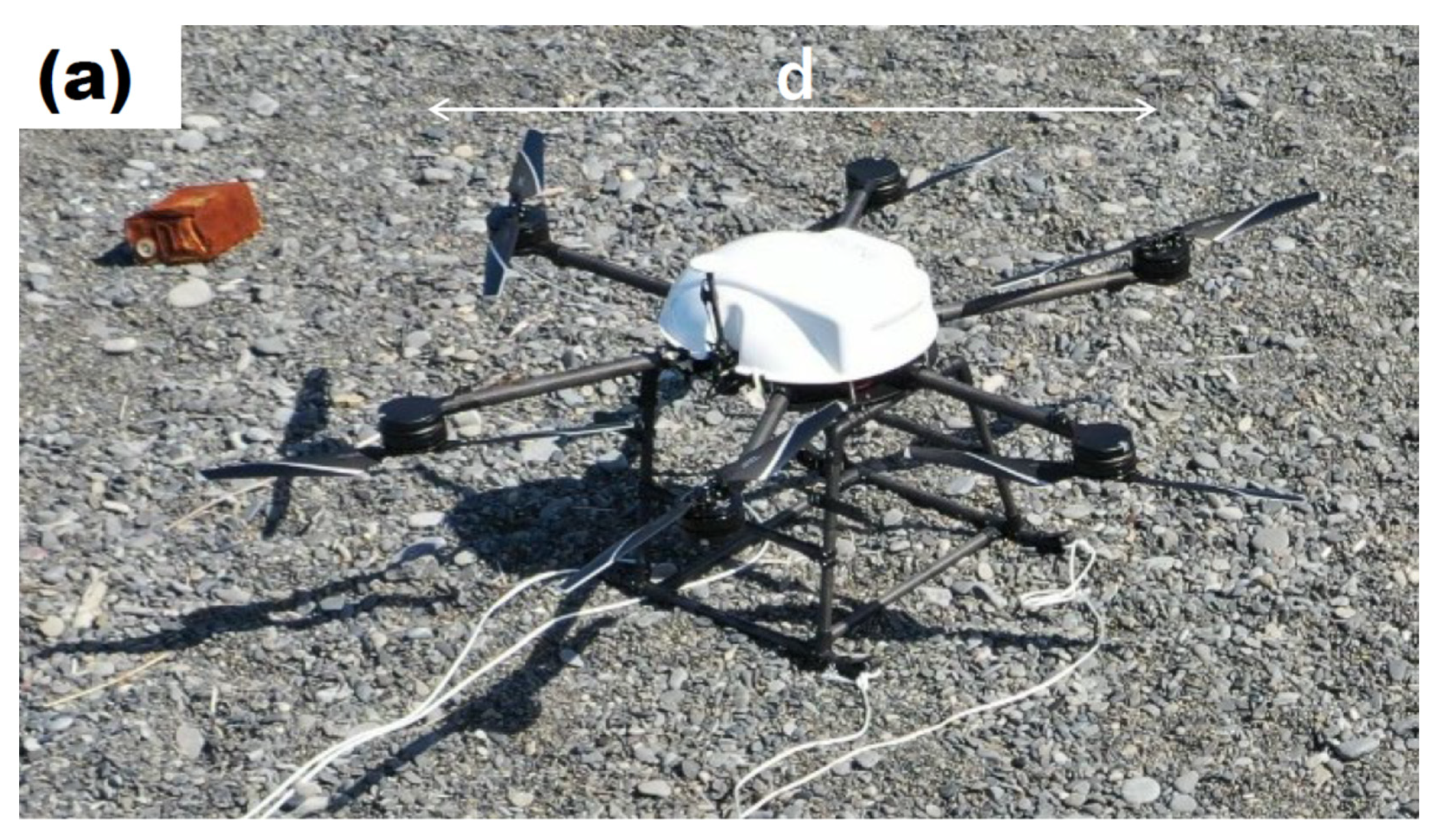
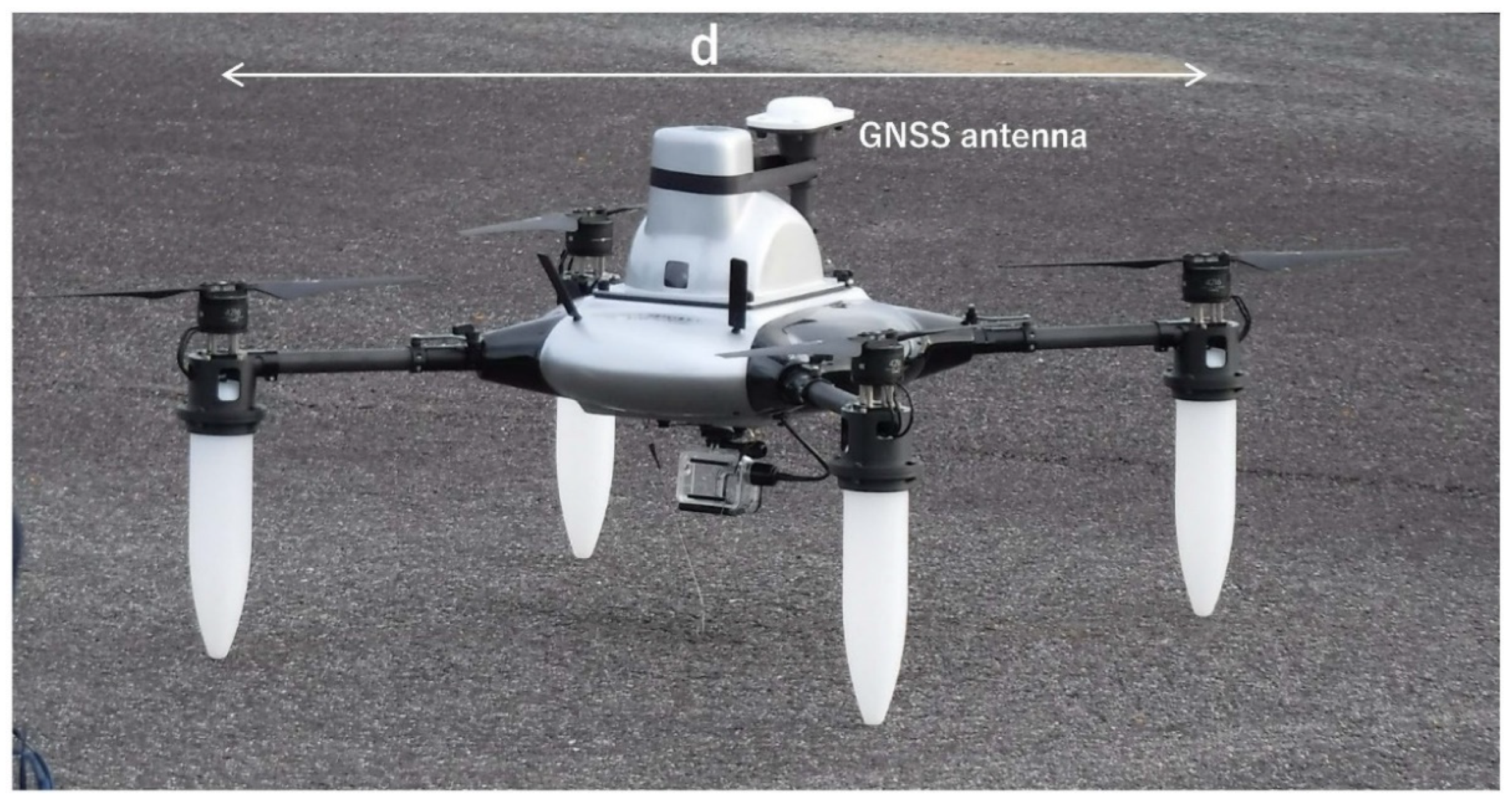
2. Materials and Methods

Two types of UAVs were used in this study. The first, used in the experiment described in Section 3.1, was a UAV incapable of landing on the sea surface (Figure 3a,b). This UAV was a model PD6B-TypeII manufactured by PRODRONE Co., Ltd (Nagoya, Japan). The maximum payload of this UAV is about 30 kg, allowing it to carry many observation instruments. A maximum flight speed of about 60 km/h can be obtained, but operation at a distance of about 1 km is objective, depending on the balance between energy consumption and communication range. The overall height of this UAV is about 55 cm, its width is about 1.4 m (d in Figure 3a), and its weight without batteries is about 11.5 kg.
The UAV used in the experiment in Section 3.2 is a lighter UAV that allows for takeoff and landing on the sea surface (Figure 4). The base aircraft used was a model PD4-AW-AQ, also manufactured by PRODRONE. It has floats and can operate like a buoy after landing on the sea surface. However, the load capacity, at about 4 kg, is much smaller than that of the first UAV. This UAV can fly at a maximum speed of 80 km/h. The overall height of this UAV is 39 cm, its width is 1.06 m (d in Figure 4), and its weight without batteries is 4.6 kg. Floats are installed below each of the four rotors to provide buoyancy. The landing operation is performed so that all floats land on the sea surface almost simultaneously (like landing on land). When lifting off from the sea surface, if the propellers are under water, the aircraft cannot be lifted stably. In that case, separation is performed by controlling the propellers to first rise into the air and then lift off after a lapse of time.
These UAVs are equipped with an inertial measurement unit (IMU) that measures the motion of the aircraft for flight control purposes. In our experiment, the motion data were obtained from the 20 Hz IMU using Wi-Fi that is easy to equip.
These UAVs were powered by a lithium-polymer battery (LIPO), and their flight time was limited to about 20 min. Stable flight was possible even when the wind speed was about 10 m/s. The data used in this study were acquired by a single-frequency and dual-frequency GNSS antenna (shown in Figure 4) and receiver mounted on the UAVs, an underwater communication device, and the IMU.

3. Experiments

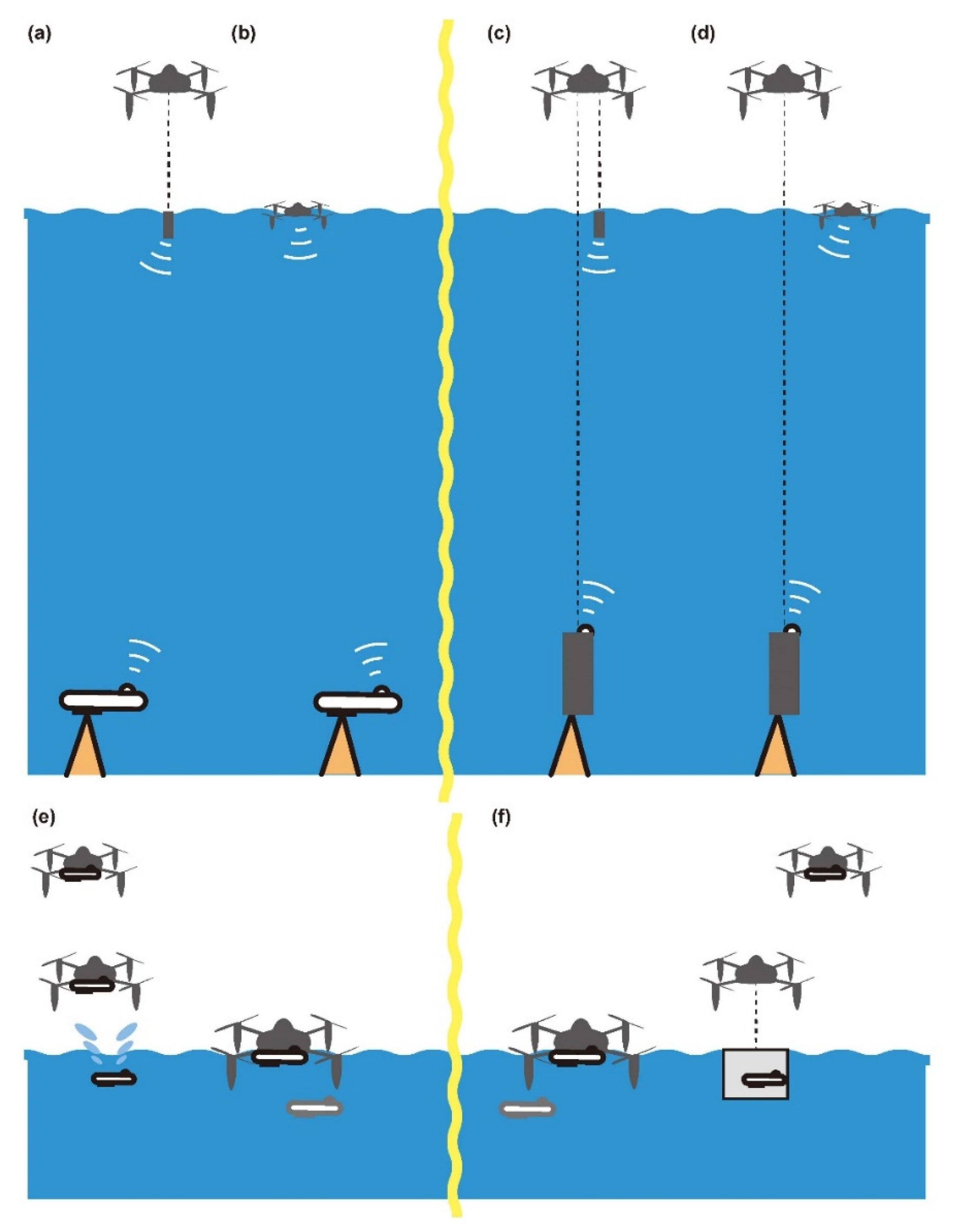
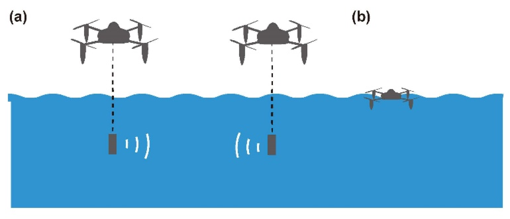
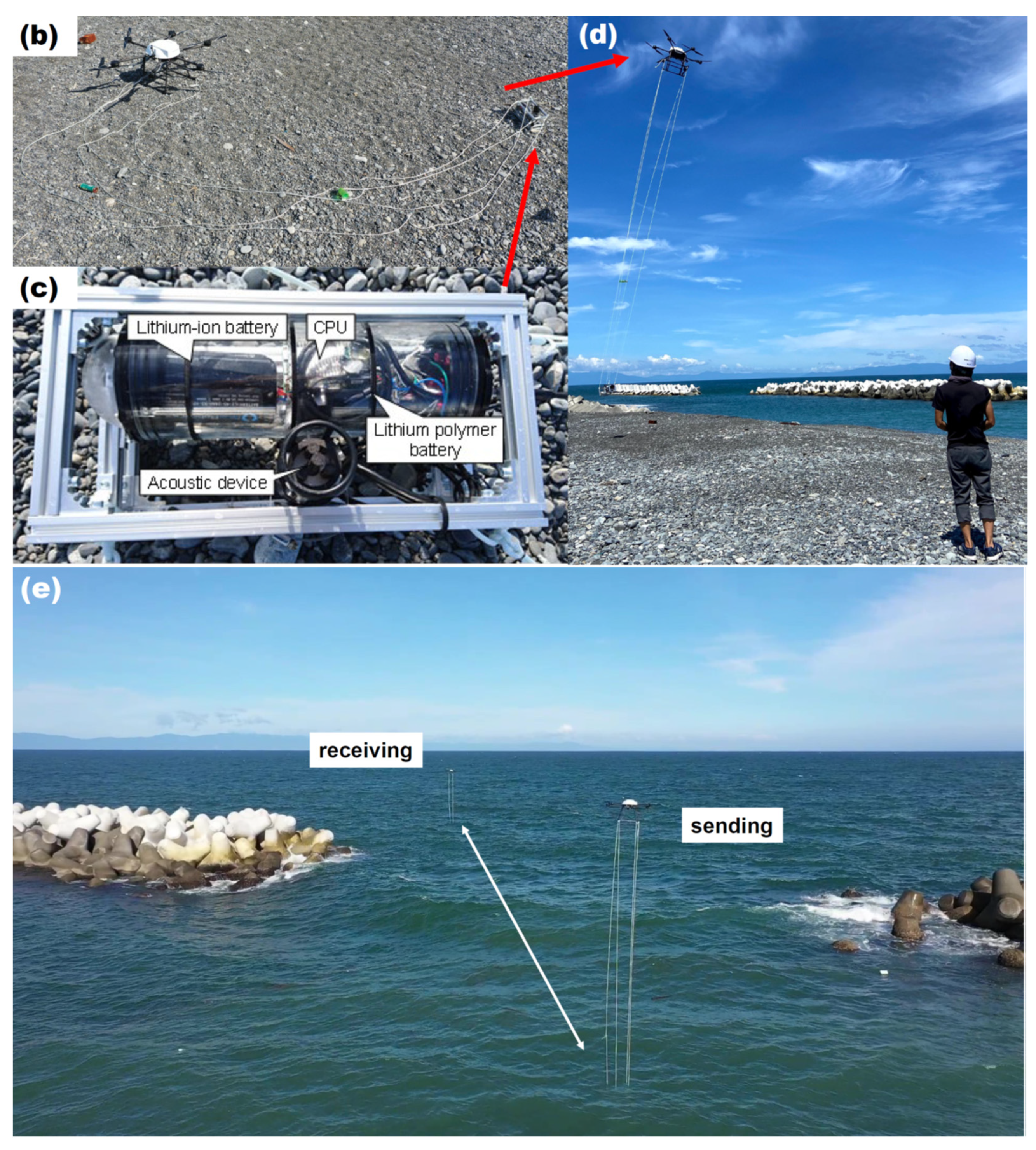
3.1. Underwater Communication with Two UAVs

3.1.1. Settings

First, we introduce the underwater equipment used in the communication experiment in Figure 3c. The underwater communication equipment includes a lithium-ion battery (LIB; 14.8 V, 18 A·h), a LIPO (5 V, 10 A·h) and a small CPU (UP Board UP-CHT01-0464) mounted in a water-resistant container. An acoustic positioning and communication device (Seatrac X150) was also installed within this container. This entire container as equipped weighed less than 4 kg. This device was lifted by nylon ropes (Figure 3d). During use, it was positioned to stay within a range of 1–3 m below the sea surface (Video S1).
We prepared two UAVs (one for acoustic signal transmission, the other for receiving) with the same acoustic device (Figure 3c), flew them near the shore, and slowly separated the sending and receiving UAVs (Figure 3e). The distance between each sonar container was determined by sonar. In addition, the distance between the UAVs in the air was also observed by the GNSS. At the end of the experiment, the equipment was lifted from the sea, and the UAVs landed at the base (Video S2).

3.1.2. Results

Figure 5a,b shows the distances recorded by the acoustic sensors in the first and second flights, respectively. In the second flight, the receiving UAV flew farther away. Figure 5c shows the differences between the acoustic sensor results and the GNSS results (A–G = acoustic sensor distance–GNSS distance). In this experiment, the acoustic signal path was no longer than 180 m (Figure 5b). Based on the comparison with the GNSS distance (Figure 5c), the distance A–G is within ±3–4 m. This can be considered as approximately the horizontal distance difference between the UAV and the underwater equipment. The average A of the G distance was about 2 m, indicating that the acoustic sensors were positioned slightly outward with respect to the flying UAVs. The ±3–4 m variation is the sum of errors and the marine current effect. This error is small enough for an underwater measurement.

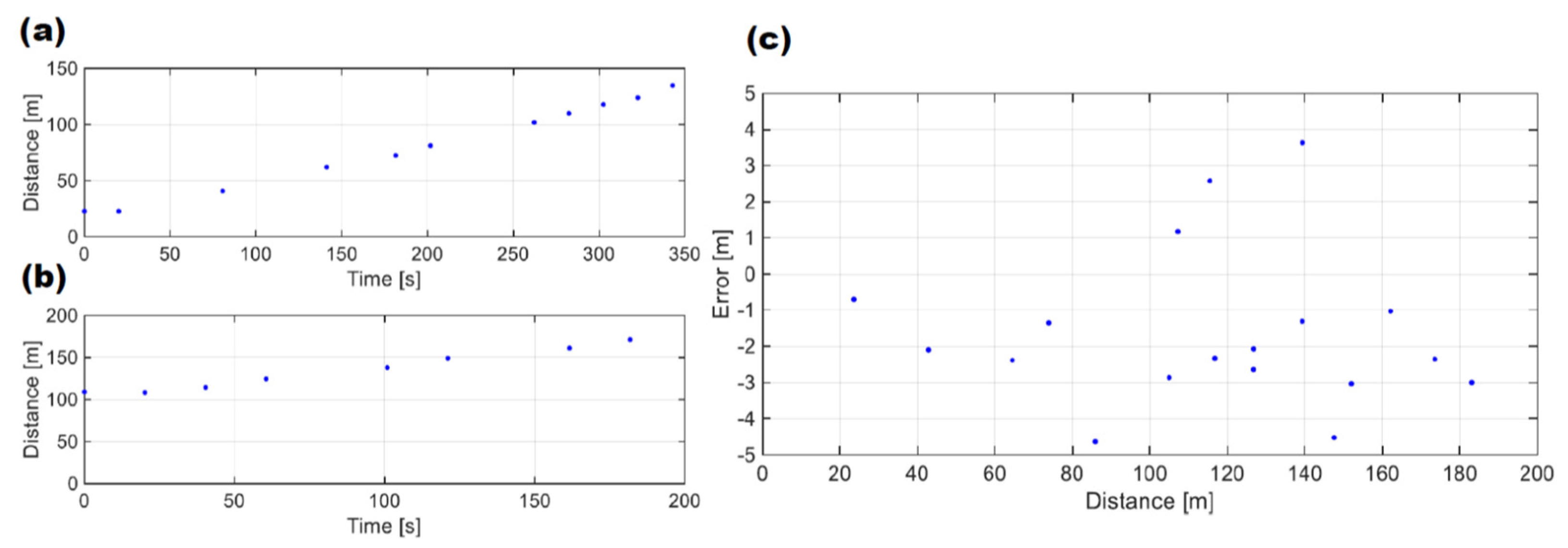
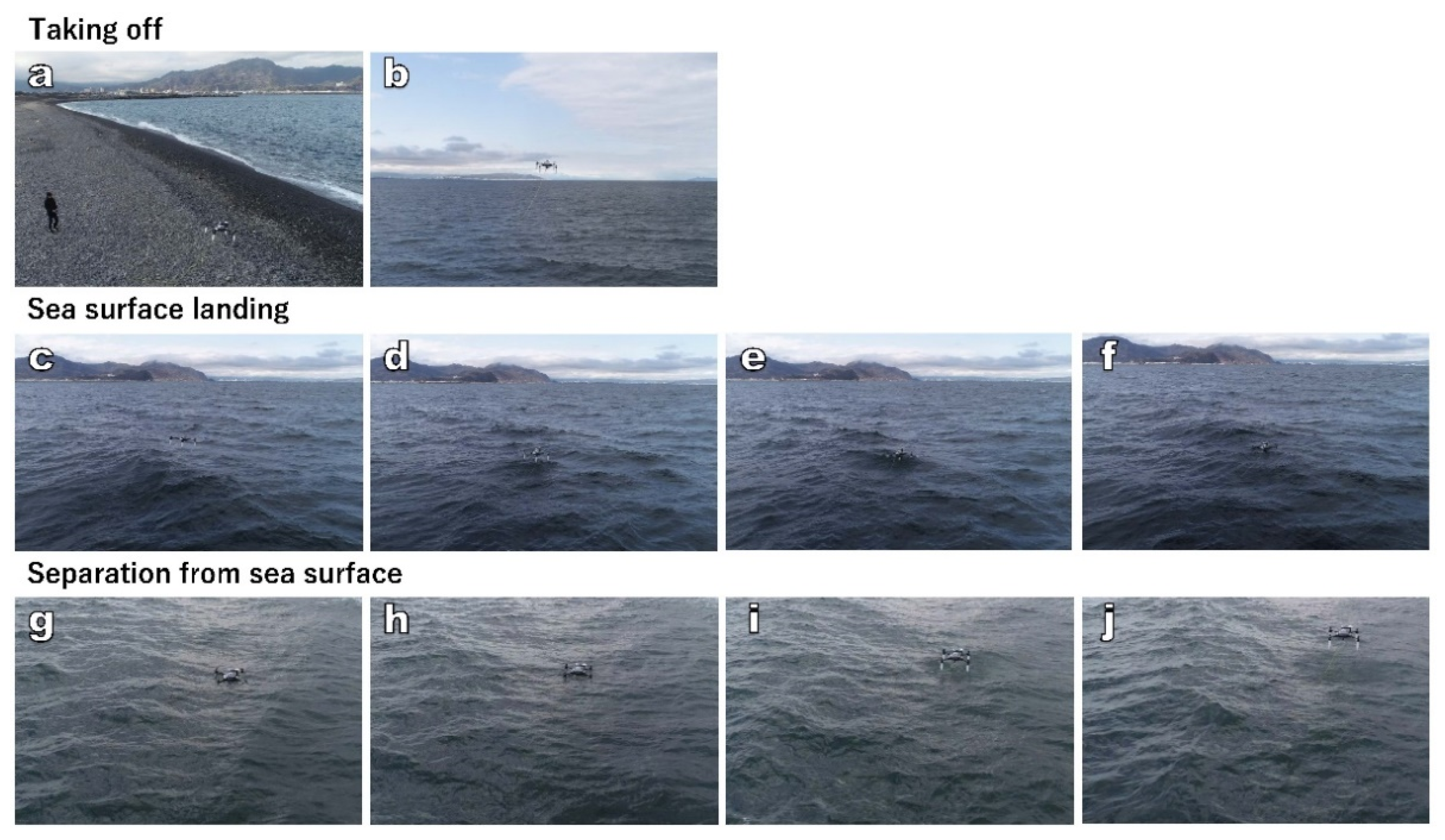
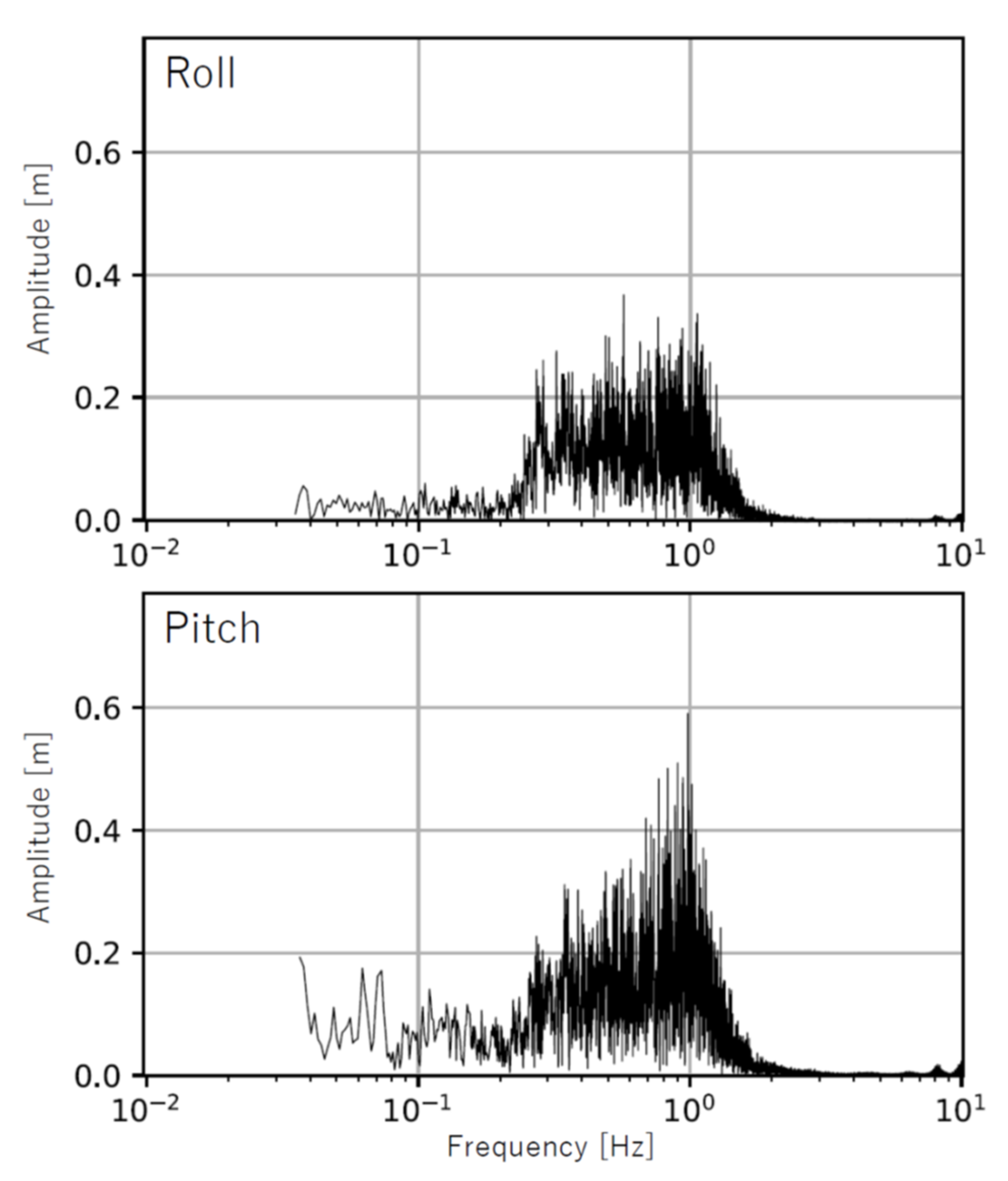
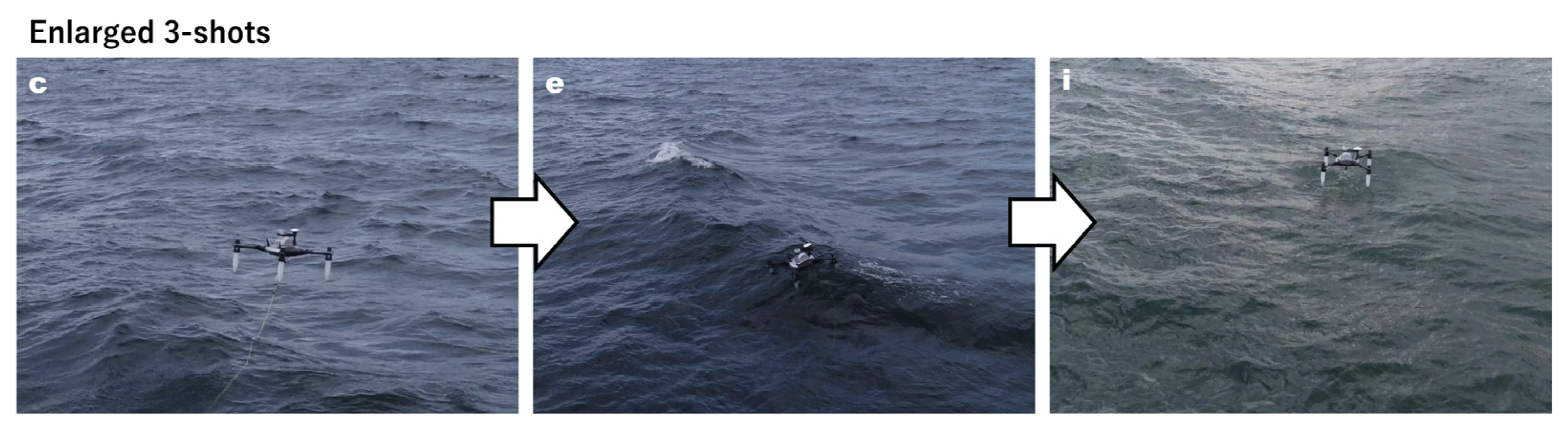
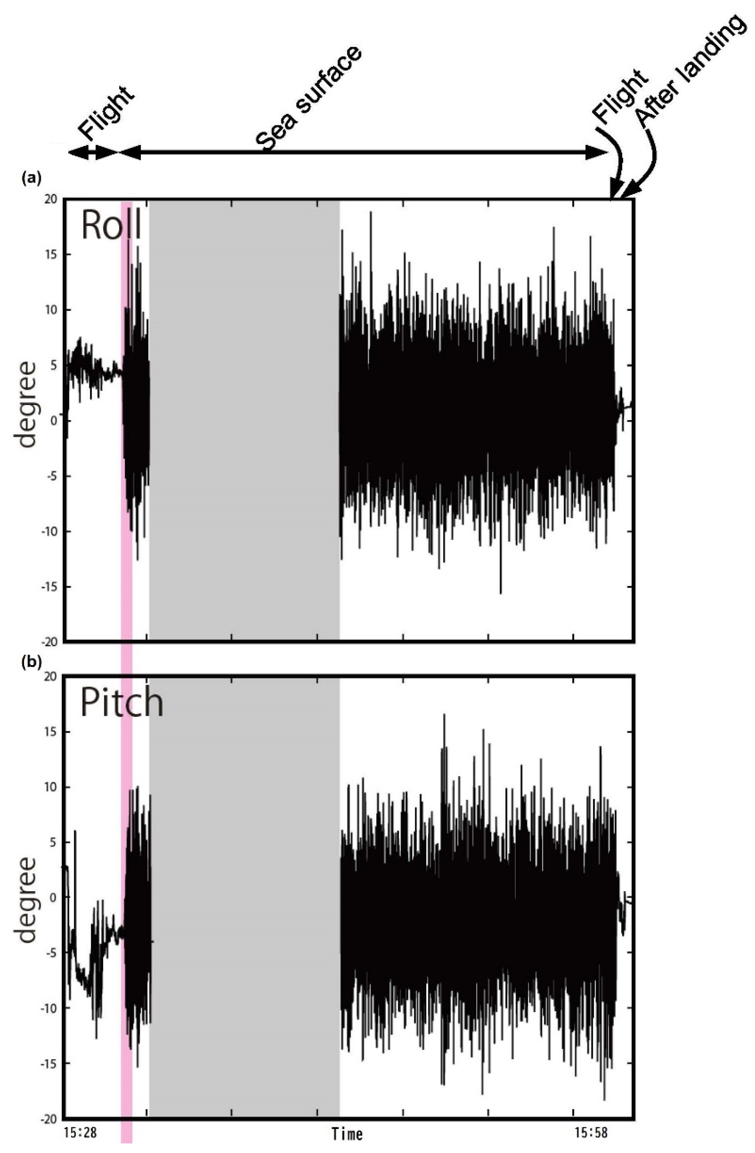
3.2. Motion Data for Sea-Surface UAV

3.2.1. Settings

Next, we conducted an experiment to determine the sway of a UAV after landing on the sea surface (Figure 4). As shown in Figure 6 and Figure 7, the UAV landed on the sea surface near the shore and recorded its sway while serving as a sea-surface buoy. The yellow fishing line connected to the UAV (Figure 6 and Figure 7) is to prevent the loss of the UAV due to drifting during the experiment and is not required for actual operation.

3.2.2. Results

Figure 8 shows IMU motion data (20 Hz) obtained in this experiment. The UAV floated on the sea surface for about 30 min. There was a communication data loss for about 10 min, which was thought to be due to water leakage. The maximum motion of the UAV body was about 19° in the roll direction and about 18° in the pitch direction. While the device floated on the sea surface, the standard deviation of motion was 4.4° (1σ) for the roll direction and 3.9° (1σ) for the pitch direction. Figure 9 further shows these Fourier spectra. In the case of motion in a vessel, it predominates around 0.1–1 Hz depending on the size, but in the case of a UAV, predominance is located around 1 Hz. It directly reflects the effects of sea-surface waves. It is also suggested that a UAV can capture the sea surface on the high-frequency side as the buoy.
The exact flight path of the UAV during the experiment is indicated by Figure 10 to examine the meteorological effect on the actual operation of the UAV. The exact UAV position was estimated by precise point positioning (PPP) analysis using dual-frequency GNSS data by RTKLIB version 2.4.2 [16] and was determined with an accuracy of about several centimeters or less. Figure 10 shows stability during takeoff from the southwestern base. After that, the variation of about ±2 m when waiting around for about 1 min is the influence of wind, and there is such a small instability at the wind speed of about 5–10 m. Then, it moves to the sea-surface landing point by automatic operation. The flight path at that time is a route that bulges slightly north of the shortest route (straight line). It is suggested that the influence of this level of wind is small for ocean observation and movement of the UAV.
The sensitivity angle of the Seatrac X150 sonar used in the experiment in Section 3.1 was about ±30°, so that the sensitivity was not impaired with the degree of sway. The behavior of the UAV as a floating body on the sea surface depends on the sea-surface environment, and ultimately the weather. The weather during the experiment was not completely calm, with a wind speed of about 5–10 m/s and a wave height of about 1 m. However, the UAV still was functional as an ocean measurement buoy. This UAV can serve as a very low-cost marine buoy, as no ship is needed for deployment or retrieval.

4. Discussion

Table 1 shows the time schedule during the communication experiment in Section 3.1. It is characterized by short flight times (2–3 min) to the observation point. Usually, when such an experiment is carried out using a vessel, it takes a long time to arrange the experimental settings and move to the observation point. UAV observation methods will reduce the cost of many observation operations.
However, in the UAV experiment, there were restrictions on flight time and equipment weight, and continuous operation for a long time was not possible. The energy source of UAVs depends on the battery system (e.g., LIBs), which is a problem. This can be solved by changing to a gasoline engine and increasing the size, but then the advantages of the UAV, which is now small and easy to operate, are lost. To solve this problem, technological innovations such as all-solid-state batteries will be required in the future.
In the case of transporting marine measurement equipment such as AUVs by UAVs (as shown in Figure 1e,f), the load capacity of the AUV also becomes important. AUVs carry underwater equipment and are usually heavy because they need to stay submerged. Thus, they are often unsuitable for transportation by UAVs. The advantage of UAVs shown in this study is their use as a sea-surface base. However, further research is required on reducing the weight of AUVs. Regarding the transportation of AUVs, it is also necessary to suppress shaking and vibration depending on the equipment, and it is also a development issue for the UAV control as suggested in the previous study [17].
In addition, many development elements are left for actual operation. Further improvement of water resistance is an important issue in actual operation, and water leakage that causes data loss as shown in Figure 8 must be avoided. Additionally, there was no problem with using Wi-Fi in this study because there was no large data transmission. In the future, when using large-scale data transmission for real-time underwater measurement, it will be necessary to consider wired communication by running a LAN cable on the nylon rope used in Section 3.1.

5. Conclusions

In this study, the advantages of using a UAV as a sea-surface base in terms of speed and maneuverability were experimentally demonstrated. The results showed that a UAV communication base exhibits robust hovering control and good performance in the presence of sway. Due to its operational efficiency and measurement speed, underwater communication technology using UAVs has the potential to be the primary method for underwater measurement up to a distance of about 1 km from the shore. However, AUV weight is still an issue, and further work is required to resolve this.

Supplementary Materials

The following are available online at https://www.mdpi.com/article/10.3390/rs13204173/s1, Video S1. Observation of two UAVs submerging their sonar sensors into the sea. Video S2. Observation of two UAVs pulling their audio sensors out of the sea and returning to land.

Author Contributions

Conceptualization, Y.Y. and T.M.; investigation, Y.Y. and T.M.; software, T.M.; validation, Y.Y. and T.M.; visualization, Y.Y. and T.M.; resources, Y.Y.; writing Y.Y. and T.M.; project administration, Y.Y.; funding acquisition, Y.Y. All authors have read and agreed to the published version of the manuscript.

Funding

This research was funded by IIS selection research grant and the University of Tokyo Excellent Young Researcher project.

Institutional Review Board Statement

Not applicable.

Informed Consent Statement

Not applicable.

Data Availability Statement

The data used in this study are available from the corresponding author upon request.

Acknowledgments

Shiyu Kojima, Masahito Ito, Naoto Sumiyoshi (PRODRONE, Co., Ltd.), and Taiju Ukai (Le Ciel DRONE, Co., Ltd.) cooperated in the use, processing, and operation of the UAV. Taiju Ukai also cooperated in filming and editing the movie.

Conflicts of Interest

The authors declare no conflict of interest.

References

  1. Allotta, B.; Costanzi, R.; Fanelli, F.; Monni, N.; Paolucci, L.; Ridolfi, A. Sea currents estimation during AUV navigation using Unscented Kalman Filter. IFAC-Papers OnLine 2017, 50, 13668–13673. [Google Scholar] [CrossRef]
  2. Matos, A.; Almeida, R.; Cruz, N. Man portable acoustic navigation buoys. In Proceedings of the MTS/IEEE OCEANS2016-Shanghai 2016, Shanghai, China, 10–13 June 2016. [Google Scholar] [CrossRef] [Green Version]
  3. Papadopoulos, G.; Fallon, M.F.; Leonard, J.J.; Patrikalakis, N.M. Cooperative Localization of Marine Vehicles using Nonlinear State Estimation. In Proceedings of the Intelligent Robots and System (IROS 2010), Taipei, Taiwan, 18–22 October 2010. [Google Scholar] [CrossRef]
  4. Abreu, P.C.; Bayat, M.; Botelho, J.; Góis, P.; Gomes, J.; Pascoal, A.; Ribeiro, J.; Ribeiro, M.; Rufino, M.; Sebastião, L.; et al. Cooperative formation control in the scope of the EC MORPH project: Theory and experiments. In Proceedings of the MTS/IEEE OCEANS 2015-Genova, Genova, Italy, 18–21 May 2015. [Google Scholar] [CrossRef]
  5. Majid, M.; Arshad, M. Design of an autonomous surface vehicle (ASV) for swarming application. In Proceedings of the IEEE/OES Autonomous Underwater Vehicles (AUV) 2016, Tokyo, Japan, 6–9 November 2016. [Google Scholar] [CrossRef]
  6. Ventura, D.; Bruno, M.; Lasinio, G.J.; Belluscio, A.; Ardizzone, G. A low-cost drone based application for identifying and mapping of coastal fish nursery grounds. Estua. Coast. Shelf Sci. 2016, 171, 85–98. [Google Scholar] [CrossRef]
  7. Yao, D.; Cheng, L.; Wu, Q.; Zhang, G.; Wu, B.; He, Y. Assessment and prediction of fishery water quality using electrochemical sensor array carried by UAV. In Proceedings of the 2019 IEEE ISOEN, Fukuoka, Japan, 26–29 May 2019. [Google Scholar] [CrossRef]
  8. Goerzen, C.; Long, Z.; Mettler, B. A survey of motion planning algorithms from the perspective of autonomous UAV guidance. J. Intell. Robot. Syst. 2010, 57, 65–100. [Google Scholar] [CrossRef]
  9. Marek, L.; Miřijovský, J.; Tuček, P. Monitoring of the Shallow Landslide Using UAV Photogrammetry and Geodetic Measurements. In Engineering Geology for Society and Territory—Volume 2; Lollino, G., Giordan, D., Crosta, G.B., Corominas, J., Azzam, R., Wasowski, J., Sciarra, N., Eds.; Springer: Cham, Switzerland, 2015. [Google Scholar] [CrossRef]
  10. Sujit, P.; Sousa, J.; Pereira, F.L. UAV and AUVs coordination for ocean exploration. In Proceedings of the Oceans 2009-Europe, Bremen, Germany, 11–14 May 2009. [Google Scholar] [CrossRef]
  11. Faria, M.; Pinto, J.; Py, F.; Fortuna, J.; Dias, H.; Martins, R.; Leira, F.; Johansen, T.A.; Sousa, J.; Rajan, K. Coordinating UAVs and AUVs for oceanographic field experiments: Challenges and lessons learned. In Proceedings of the 2014 IEEE International Conference on Robotics and Automation (ICRA), Hong Kong, China, 31 May–7 June 2014; pp. 6606–6611. [Google Scholar] [CrossRef] [Green Version]
  12. Ravell, D.A.M.; Maia, M.M.; Diez, F.J. Modeling and control of unmanned aerial/underwater vehicles using hybrid control. Control Eng. Pract. 2018, 76, 112–122. [Google Scholar] [CrossRef]
  13. Wu, Y. Coordinated path planning for an unmanned aerial-aquatic vehicle (UAAV) and an autonomous underwater vehicle (AUV) in an underwater target strike mission. Ocean Eng. 2019, 182, 162–173. [Google Scholar] [CrossRef]
  14. Ivanovic, A.; Polic, M.; Salah, O.; Orsag, M.; Bogdan, S. Compliant net for AUV retrieval using a UAV. IFAC-Papers OnLine 2018, 51, 431–437. [Google Scholar] [CrossRef]
  15. Watanabe, K.; Utsunomiya, K.; Harada, K.; Watanabe, Y. A Concept of Coastal Sea Monitoring System from Sky to Water. In Proceedings of the 3rd World Congress on Civil, Structural, and Environmental Engineering (CSEE’18), Budapest, Hungary, 8–10 April 2018. [Google Scholar] [CrossRef]
  16. Takasu, T. RTKLIB Ver. 2.4.2: An Open Source Program Package for GNSS Positioning. Available online: http://www.rtklib.com/ (accessed on 18 October 2021).
  17. Guerrero-Sánchez, M.-E.; Hernández-González, O.; Lozano, R.; García-Beltrán, C.-D.; Valencia-Palomo, G.; López-Estrada, F.-R. Energy-based control and LMI-based control for a quadrotor transporting a payload. Mathematics 2019, 7, 1090. [Google Scholar] [CrossRef] [Green Version]
Figure 1. Conceptual schematics for underwater communication using UAVs and AUVs. (a) Hanging an acoustic base station from a UAV hovering above the sea surface during an AUV survey. (b) Acoustic base station installed on a sea-surface UAV during an AUV survey. (c) Hanging both an underwater sonar and acoustic base station from a hovering UAV. (d) Suspending an underwater sonar from a hovering UAV with an acoustic base station installed on a sea-surface UAV. (e) Transporting a UAV with an AUV. (f) Retrieving an AUV with a UAV.
Remotesensing 13 04173 g001
Figure 2. Experimental setup in this study. (a) Underwater communication experiment with two UAVs for determining stability at a distance. (b) Determination of sea-surface sway of a UAV used as a buoy.
Remotesensing 13 04173 g002
Figure 3. (a) The UAV used in the experiment in Section 3.1. (b) Observing UAV with an underwater communication device suspended by nylon ropes. (c) Suspended device. The batteries, CPU, and acoustic device are included in one container. (d) UAV takeoff. At the lower right is the operator-controlling the UAVs. (e) Receiving UAV moving slowly away from the sending UAV.
Remotesensing 13 04173 g003aRemotesensing 13 04173 g003b
Figure 4. Sea-surface UAV.
Remotesensing 13 04173 g004
Figure 5. (a,b) Changes in the distance between two UAVs. The horizontal axis is the elapsed time, and the vertical axis is the distance recorded by the acoustic devices. The results in (a) and (b) show the distances for the first and second flights, respectively. (c) Difference between the distance measured by the underwater acoustic devices and the GNSS mounted on the UAV. The horizontal axis is the GNSS distance, and the vertical axis is the distance difference (acoustic sensor distance–GNSS distance).
Remotesensing 13 04173 g005
Figure 6. Snapshots of UAV operation as a buoy. (a) UAV takeoff from the base. (b) UAV flying to the observation point. (cf) Snapshots of UAV landing. (gj) Snapshots of UAV lifting off.
Remotesensing 13 04173 g006
Figure 7. Enlarged snapshots of UAV operation: (c), (e), and (i) in Figure 6.
Remotesensing 13 04173 g007
Figure 8. IMU recording of the (a) roll component and (b) pitch component for about 30 min. The horizontal axis is time (JST, UTC+0900). During the period with gray shading, no data were acquired. Red shading denotes the period of landing on the sea surface.
Remotesensing 13 04173 g008
Figure 9. Fourier spectra of IMU data in the roll and pitch components while floating on the sea surface.
Remotesensing 13 04173 g009
Figure 10. Precise UAV position from takeoff to sea-surface landing determined using dual-frequency GNSS.
Remotesensing 13 04173 g010
Table 1. Time schedule during the communication test in Section 3.1 (two trials).
Time [hour]
(JST, UTC+0900)
Action
14:44Takeoff
14:46Measurement start
14:52Measurement end
14:54Landing
  
16:23Takeoff
16:25Measurement start
16:30Measurement end
16:32Landing
Publisher’s Note: MDPI stays neutral with regard to jurisdictional claims in published maps and institutional affiliations.

