Technical Note

Detecting Moving Target on Ground Based on Its Shadow by Using VideoSAR

1
College of Electronic Science and Engineering, National University of Defense Technology (NUDT), Changsha 410073, China
2
Beijing Institute of Remote Sensing Information, Beijing 100192, China
*
Author to whom correspondence should be addressed.
Remote Sens. 2021, 13(16), 3291; https://doi.org/10.3390/rs13163291
Submission received: 6 July 2021 / Revised: 18 August 2021 / Accepted: 18 August 2021 / Published: 20 August 2021

Abstract

:
Video synthetic aperture radar (VideoSAR) can detect and identify a moving target based on its shadow. A slowly moving target has a shadow with distinct features, but it cannot be detected by state-of-the-art difference-based algorithms because of minor variations between adjacent frames. Furthermore, the detection boxes generated by difference-based algorithms often contain such defects as misalignments and fracture. In light of these problems, this study proposed a robust moving target detection (MTD) algorithm for objects on the ground by fusing the background frame detection results and the difference between frames over multiple intervals. We also discuss defects that occur in conventional MTD algorithms. The difference in background frame was introduced to overcome the shortcomings of difference-based algorithms and acquire the shadow regions of objects. This was fused with the multi-interval frame difference to simultaneously extract the moving target at different velocities while identifying false alarms. The results of experiments on empirically acquired VideoSAR data verified the performance of the proposed algorithm in terms of detecting a moving target on the ground based on its shadow.

Graphical Abstract

1. Introduction

The synthetic aperture radar (SAR) combines pulse compression and the synthetic aperture to obtain high resolution images along the directions of the range and the azimuth. It is regarded as an important means of earth observations and battlefield surveillance [1,2,3,4]. A military target may not stay motionless but seek to attack while constantly moving to improve its probability of survival. The conventional SAR imaging technique can provide only static observations of the given scene. The combing ground moving target indication (GMTI) technique partially enables SAR to detect moving targets. This method extracts some parameters of moving targets from moving bright spots after SAR imaging, such as the along track velocity [5], the variations in traffic [6], etc. However, such a GMTI/SAR technique incurs a significant computational load and has a complex implementation procedure [7,8,9]. Researchers at the Sandia National Laboratories have integrated SAR imaging with video-capturing technology to develop the video synthetic aperture radar (VideoSAR) technique [10]. Owing to its high frame rate of ground imaging, this technique can represent dynamic changes in a specific region on the ground at a high resolution in real time and is regarded as an innovation in military surveillance and reconnaissance [11].
The shadow of a moving target can be used as an object of detection in VideoSAR [12,13,14,15]. This has the theoretical advantages of a high positioning accuracy, high rate of detection, and low minimum detectable velocity. In [15], the authors discussed the mechanism of formation of the shadow of a moving target in a SAR image, and proposed a moving target detection (MTD) method as well as a method to assess it. The authors of [16] used the maximum threshold segmentation method to calculate binary images and extract a moving target in them by combining the background difference and the frame difference algorithms. In [17], a shadow-based low-RCS MTD method for the Ka band was proposed based on the geometric characteristics of the moving shadow. The authors of [18] presented a method of local feature analysis based on single-frame images that can accurately detect the shadow of a moving target. In [19], a dual fast region-based convolutional neural network for SAR images in the range Doppler (RD) spectrum domain was proposed to detect a moving target on the ground, but these algorithms have high requirements for training data [20] and insufficient generalization ability. All these algorithms can extract the shadow of a moving target on the ground. However, shadow detection by using VideoSAR has some inherent defects, especially in the case of a slowly moving target. According to the mechanism of shadow formation in VideoSAR, the main causes of false alarm include temporal variations in scattering, variations in the shadow with changes in the viewing angle, energy displacement and shifting of the target, and SAR speckle noise [21]. A clear and stable shadow is thus challenging to obtain in VideoSAR data. Moreover, the detection box obtained via difference-based algorithms has such defects as misalignments and fractures that degrade the detection-related performance of VideoSAR.
This study used the results of past research and the characteristics of sequences of images in VideoSAR to propose a robust method to detect the shadow of a moving target on the ground. In light of the problem whereby the conventional frame difference algorithm cannot detect a target with varying velocity, the proposed algorithm accumulates the results of background frame difference over several intervals (multiple intervals), and then segments the cumulative results to form a binary image to identify slowly and quickly moving targets. Moreover, in light of the problem whereby the conventional frame difference algorithm cannot extract the entire region of the moving target, which leads to misaligned and fractured results of detection, the proposed algorithm combined background frame difference and multi-interval frame difference to prevent the front-and-rear fracture of the detection boxes to improve the accuracy of MTD.
The remainder of this paper is organized as follows: Section 2 details the principles of conventional difference-based algorithms and the defects in their application to VideoSAR. Section 3 describes steps of the implementation of the proposed algorithm as well as its advantages. Experiments on empirically acquired VideoSAR data are carried out in Section 4 to test the effects of the proposed algorithm, and the conclusions of this study are drawn in Section 5.

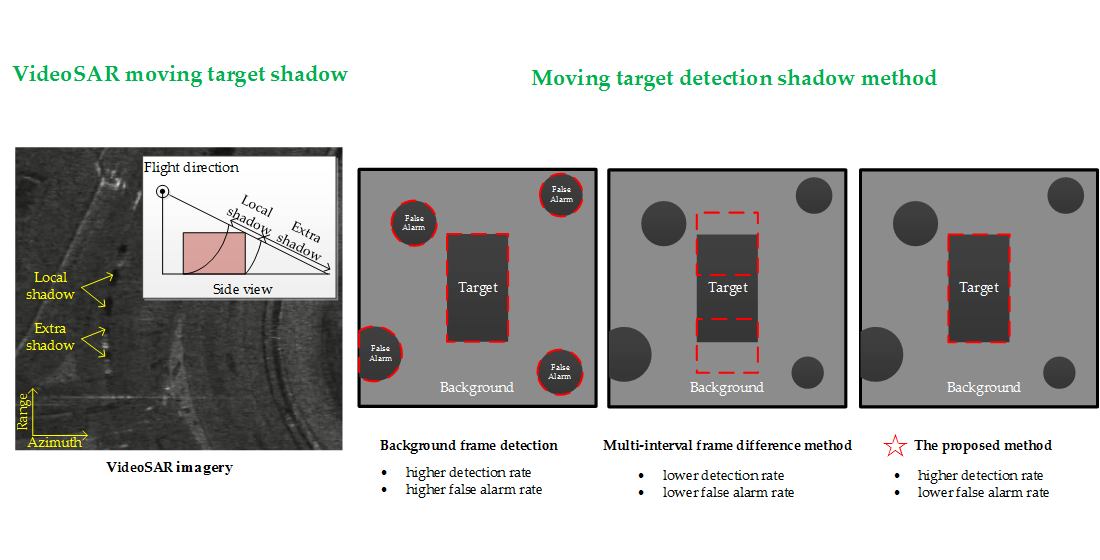
2. Principles and Deficiencies of Difference-Based Algorithms

A moving target can be detected through its shadow in VideoSAR, where a moving shadow can in turn be detected via the difference operation. Difference-based algorithms are widely used to detect changes in videos due to their simplicity and high efficiency. They include background difference and frame difference algorithms. This section provides a brief introduction and analysis of difference-based algorithms.
The background difference algorithm builds a background template and compares it with a sequence of images one by one to separate the static background from the moving target [15]. This process is simple in principle, and easy to implement and adapt to a dynamic background. It is frequently used in scenes where the background does not change or does so only slowly. Background modeling is the key step here, and is commonly implemented via mean background modeling, Gaussian background modeling, and nuclear density estimation-based background modeling [22].
Frame difference is an algorithm that removes the static region from an image and preserves the moving target by subtracting adjacent frames. It incurs a low computational load and is easy to implement. In applications, however, this algorithm exhibits such defects as misaligned detection boxes and sensitivity to the intensity of ground scattering. Moreover, targets with low velocities are difficult to detect because variations between adjacent frames are minor.
Figure 1 shows the basic principle of the background difference and frame difference algorithms. Three frames before the given one are used to form the background template. The grayscales of the background and the target shadow are assumed to be homogeneous and constant to simplify the derivation. C t and C b in the figure represent the grayscales of the target shadow and the background shadow, respectively. It is clear that both the background difference algorithm and the frame difference algorithm can partially extract the moving region. The position of the moving target obtained via background difference has a significant offset (see the center of the white rectangle in Figure 1a), and the detection box obtained using frame difference is fractured. Such problems affect the accuracy of shadow detection and are thus important to solve.

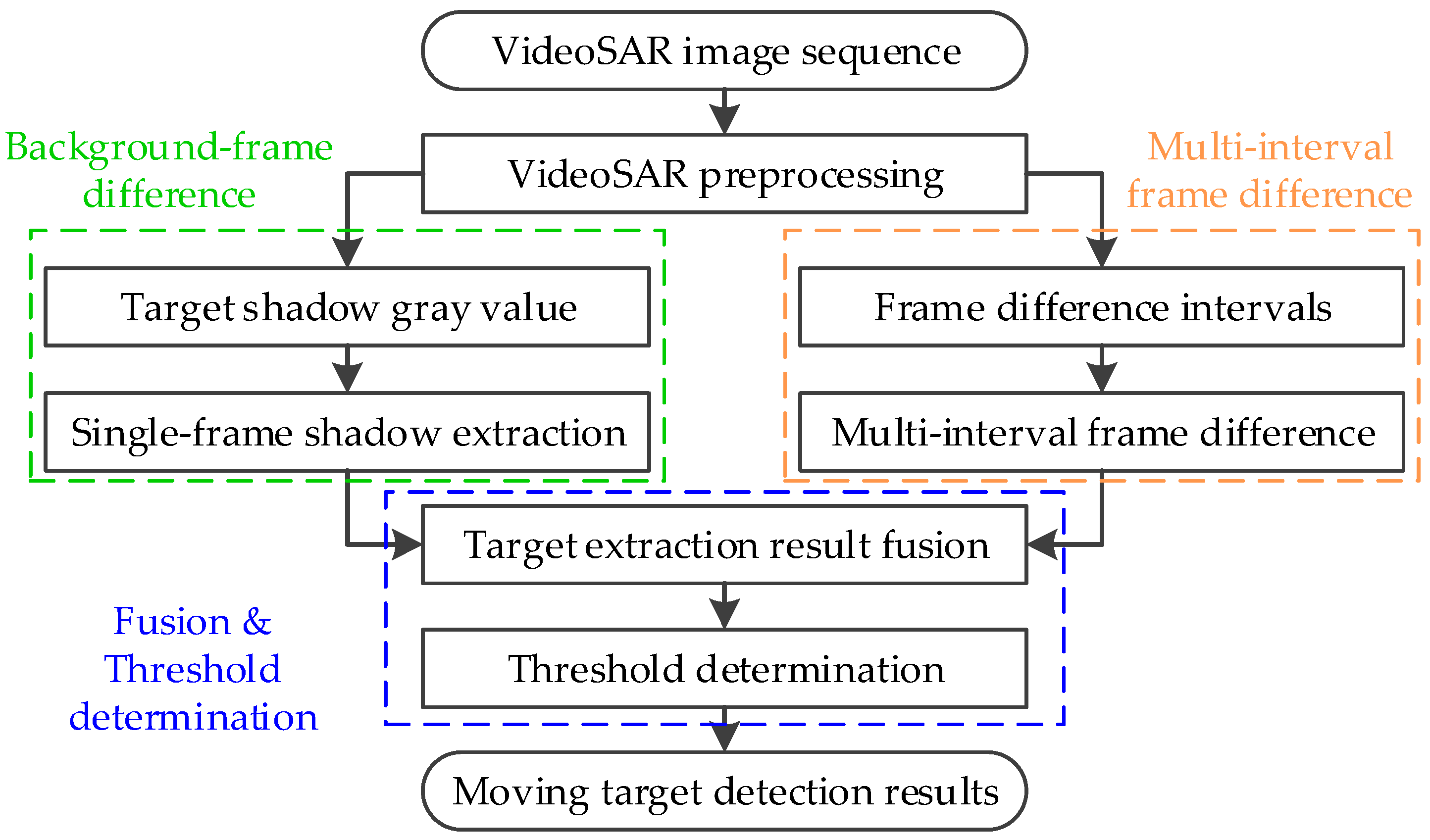
3. Fusing Background Frame Detection and Multi-Interval Frame Difference for MTD

To address the deficiencies of difference-based algorithms in MTD by using VideoSAR, this section combines background frame detection and multi-interval frame difference. By accumulating the results of multi-interval frame difference, the proposed algorithm can drastically improve the detection of a slowly moving target, and background frame detection can yield more accurate positions of the moving target. The main procedure of the proposed algorithm is discussed in this section.

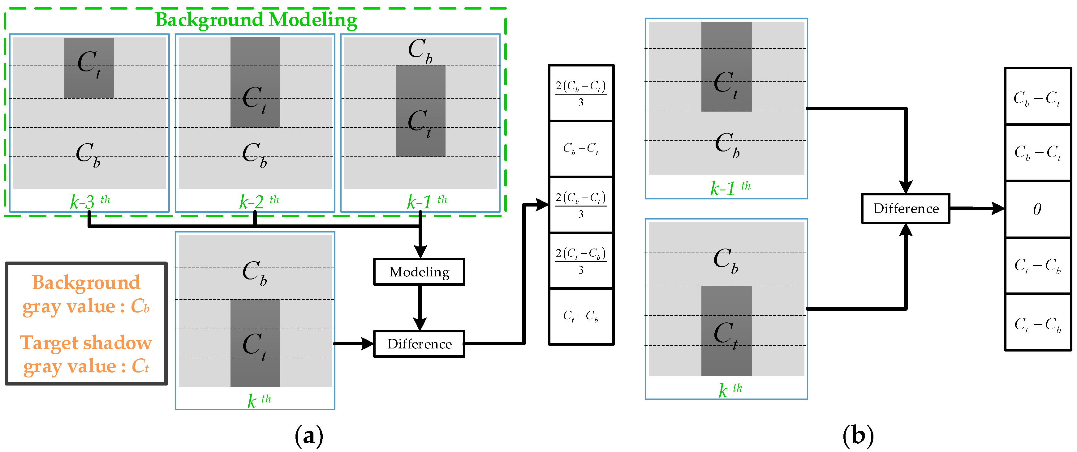
3.1. Background Frame Detection

The shadow of a moving target appears as a low grayscale area in the SAR image, and its grayscale range is related to the total time for which the shadow of the ground object is detected. The intensity of the shadow region of the moving target can be written as (detailed deduction has been provided in [21]):
P m o v i n g = k F n T 0 B n ( 1 + ( 1 q ) S N R a r e a )
where k is the Boltzmann constant, F n are the noise coefficients of noise of the receiver, T 0 is the effective temperature of noise in receiver, B n is the spectral density of effective noise, S N R a r e a is the signal-to-noise ratio of the area target, and q is a scale factor related to the duration for which the shadow appears. It is given by:
q = L a v t 2 ρ a V r r λ c
where L a is the azimuthal length of the target, ρ a is its azimuthal resolution, v t represents the velocity of the radar platform, r is the nearest range between the radar and the target, and λ c is the carrier wavelength. Considering Equations (1) and (2), it is clear that the intensity of the shadow of the moving target is closely related to the velocity of the target. Only a target moving within a certain range of velocity forms a macroscopic shadow. When the velocity of the target exceeds a certain value (q decreases to close to zero), the shadow of the moving target blends into the background instead of appearing as a distinct feature.
Thus, the boundary value of the grayscale range of the shadow of the moving target is:
{ C m i n = k F n T 0 B n C m a x = k F n T 0 B n ( 1 + S N R a r e a )
Assuming that the given frame is I c ( x , y ) , where ( x , y ) represents the coordinate of an arbitrary pixel, I s e ( x , y ) is the binary image obtained via processing for shadow detection, the background frame detection can be expressed as:
I s e ( x , y ) = { 1 , C m i n I c ( x , y ) C m a x 0 , I c ( x , y ) < C m i n   o r   I c ( x , y ) > C m a x
This operation can extract all regions with similar gray values to those of the shadow of the moving target, including targets moving at different velocities in a static, low RCS background. This process thus yields many false alarms while accurately extracting a moving target, where the number of false alarms is much higher than that of instances of the real target.

3.2. Multi-Interval Frame Difference

Conventional frame difference involves subtracting the frame adjacent to the given one from it to highlight moving objects. It has the advantages of low computational load and a simple implementation, but yet has an inherent defect in the case of detecting a slowly moving target. A modified method called symmetry difference is proposed to solve this problem. It involves fusing the results of differences of three frames (from front and rear to I c ) [23]. An efficient algorithm called multi-interval frame difference is used in this paper, and the details of its implementation are as follows:
Assume that N frames in front of and behind I c are used and stacked into a 3D matrix F . For each frame F i in F , we calculate the difference between it and I c , and add all these results to form I t e m p . Then, I t e m p is compared with a preset threshold T S in a pixel-by-pixel manner and transferred into a binary image I m d ( logical ( ) represents a logical operation), which can be written as:
I t e m p = i = 1 N logical ( | F i I c | )
I m d ( x , y ) = { 0 , I t e m p ( x , y ) T S 1 , I t e m p ( x , y ) > T S
The interval used in frame difference affects detection-related performance. Assume that v t is the velocity of the target, f r a t e is the frame rate, and L t is the projected length along its velocity. It is clear that the best moment to calculate the frame difference is when the target moves exactly by distance L t . The ideal interval N i d e a l must satisfy the following equation:
N i d e a l = f r a t e L t v t
A slowly moving target cannot be extracted via conventional frame difference because changes between adjacent frames are minor. Hence, it is necessary to calculate the differences between frames over a wider interval. The value of N is related to the target’s velocities in the observed scene. Normally, we need to ensure that the distance moved by the slowest target during ( N 1 ) / 2 frames is longer than half of its own length. This can be expressed as:
( N 1 ) V min 2 f r a t e L t 2
where V min denotes the minimum velocity of the target. It is easy to deduce the range of values of N :
N f r a t e L t V min + 1 , N Z
where Z contains all integers. The minimum N value required to meet the detection of slow moving targets is determined according to Equation (9), and the N-frame difference results are accumulated according to Equation (5). By accumulating the results of multi-interval frame difference, we can simultaneously detect a target moving with different velocities. However, due to characteristics of difference-based algorithms, the detection box and the real position of the shadow of the target are misaligned, and lead to erroneous results.

3.3. Fusion and Threshold Determination

Background frame detection can be used to obtain accurate positions of the moving target and the intact regions of coverage, but also leads to a large number of false alarms in a low-RCS background. Multi-interval frame difference can simultaneously detect the target at different velocities but incurs problems including the misalignment and fracture of the detection boxes. Therefore, this paper proposes an MTD algorithm by fusing these two algorithms.
The area of overlap of shadow is obtained via the logical AND operation:
I l a p = I s e I m d
I l a p is then added to the result of background frame detection I s e , and the weighted shadow is extracted. Pixels that are detected by both algorithms are assigned the value “2”, and other pixels are assigned “1”.
I f u s i o n = I l a p + I s e
Finally, we extracted the region of interest (ROI) from I f u s i o n . The ROI of a moving target is normally detected by both algorithms, and thus has many pixels with the value 2. The ROI of a low RCS, static background is detected only by background frame detection, and thus has pixels of value 1. In practice, a threshold ROI (TROI) can be set to distinguish between the real target and a false alarm. This is called threshold determination:
ROI ( k ) { real   target   ,   S w e i g h t ( k ) / S u n w e i g h t ( k ) T R O I false   alarm   ,   S w e i g h t ( k ) / S u n w e i g h t ( k ) < T R O I
where S w e i g h t = s u m ( ROI ( k ) ) is the weighted area of and S u n w e i g h t = n u m e l ( ROI ( k ) ) is its unweighted area. It is easy to obtain the range of values of T R O I , as in [1,2]. In general, T R O I is set between 1.3 and 1.5 for satisfactory detection probability of moving target at all speeds, while suppressing false alarms as much as possible.
Figure 2 shows the effect of the proposed algorithm. It is clear that single frame shadow extraction can yield an accurate and intact shadow region and leads to many false alarms. Multi-interval frame difference can be used to acquire information on the moving region and yields misalignment and fractures in the detection box. After fusion, we can obtain an accurate position of the target with a low false alarm rate.
A flowchart of the proposed VideoSAR-based MTD algorithm is shown in Figure 3. The VideoSAR preprocessing procedure is first applied to the input VideoSAR image sequence, including the inter-frame registration algorithm and the speckle suppression algorithm. After registration and noise suppression, one can obtain an image sequence with clear targets and a smooth background. Following this, the background frame detection step (shown in the green box) and the multi-interval frame difference step (shown in the orange box) are applied to the results of preprocessing, respectively. Finally, the fusion and threshold determination step (shown in the blue box) is used to increase the accuracy of detection of the shadow of a moving target on the ground and reduce false alarms.

4. Experimental Results and Discussion

Empirical VideoSAR data were used to verify the performance of the proposed method. The data were captured at Kirtland Air Force Base and published by Sandia National Laboratories (SNL) [10]. The video contained 900 frames captured at a rate of 29.97 Hz. The height and width of each frame after preprocessing were 720 pixels and 650 pixels, respectively. The methods proposed in [24] were used to register the image sequence and suppress speckle noise. The method to reduce the number of false alarms proposed in [21] was applied after fusion.

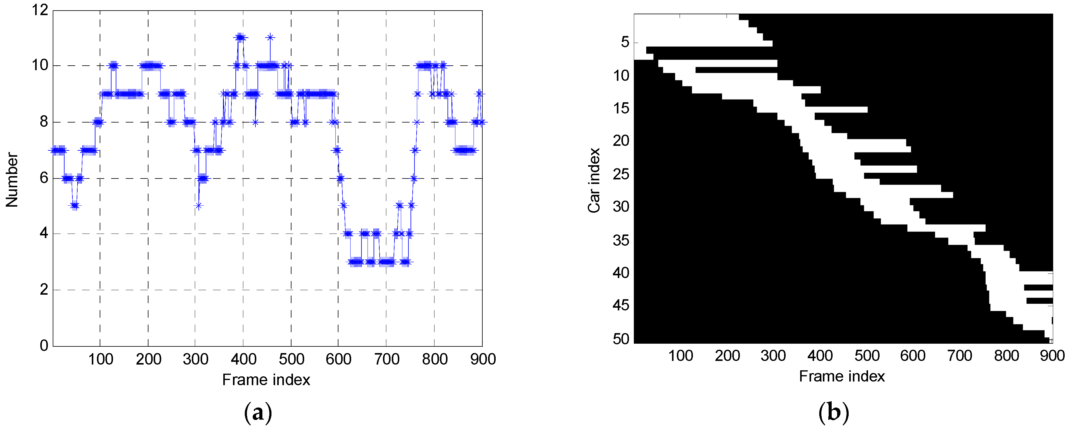
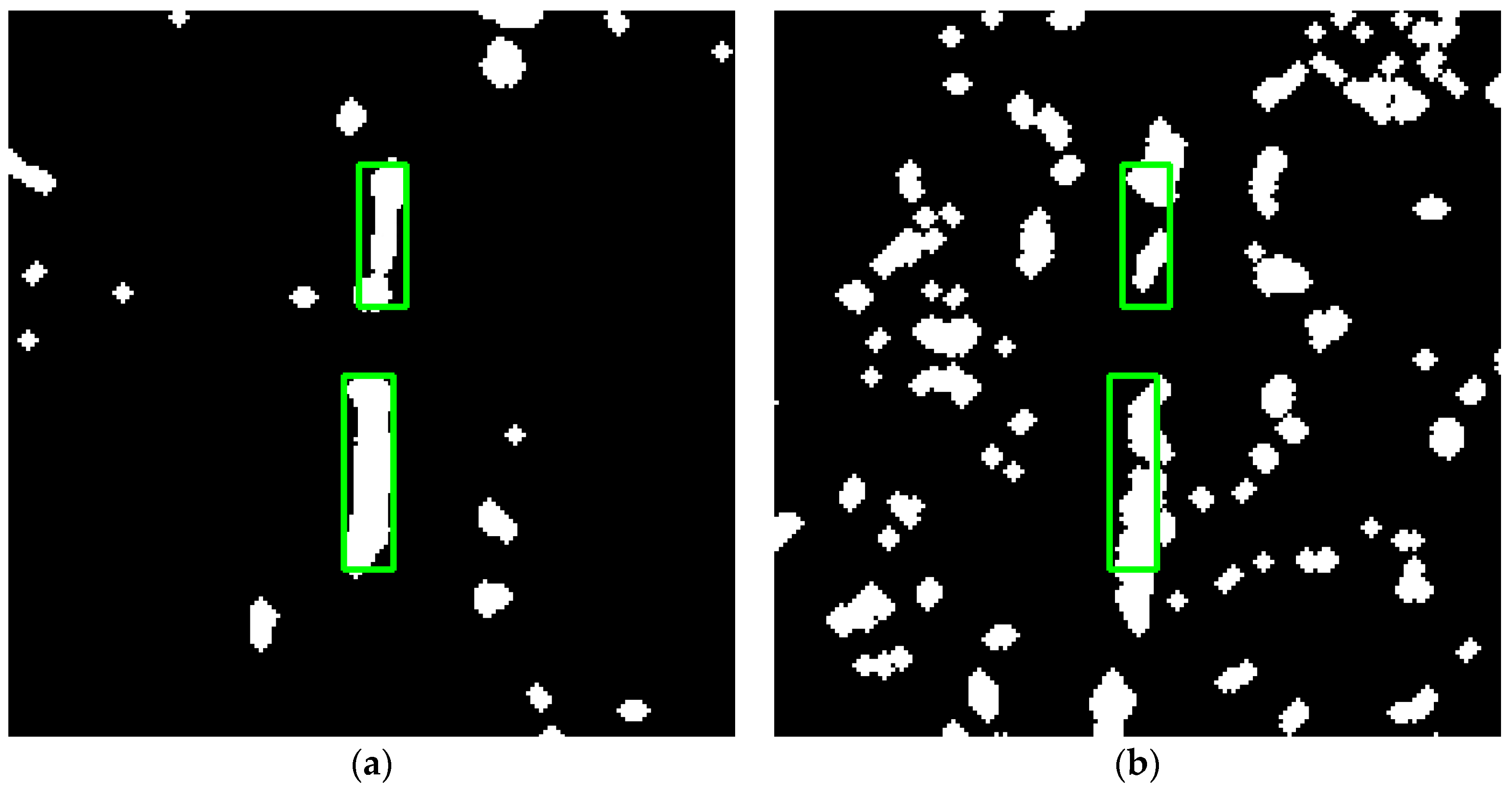
4.1. Results of Shadow Marking

To quantitatively analyze the results of shadow detection, the shadow of the moving target was marked for SNL VideoSAR data, and the area of the shadow was manually marked frame by frame. A total of 50 moving targets (vehicles) were marked in 900 frames of the video, including 33 vehicles on the left road and 17 on the right road. The results of marking of the moving vehicles in the SNL VideoSAR data are shown in Figure 4, the number of moving vehicles is plotted in Figure 4a, from three to 11 in each frame, and the motion of 50 vehicles in and out the frame is shown in Figure 4b.
Due to limitations of space, only the results of the 23rd and the 551st frames are shown here. Figure 5 shows the results of detection of the shadow of a moving target on the ground after VideoSAR registration preprocessing. The shadows of six moving cars are marked in the 23rd frame in Figure 5a and in the 551st frame shown in Figure 5b.

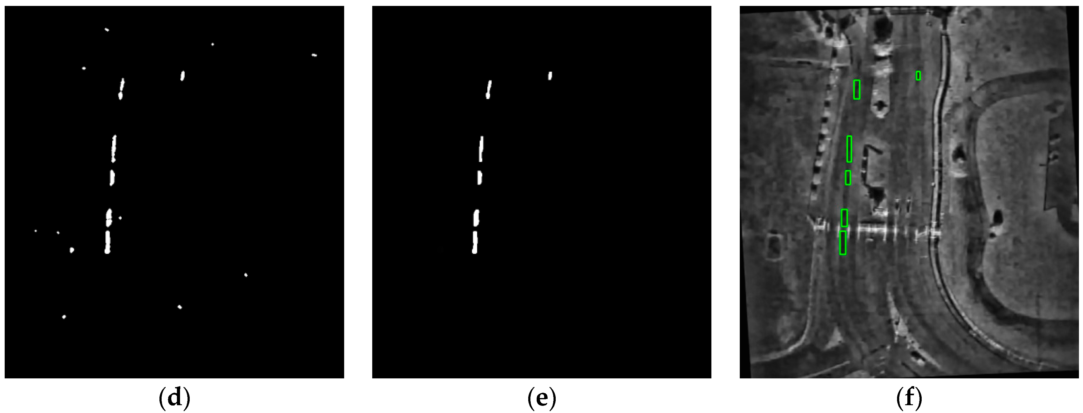
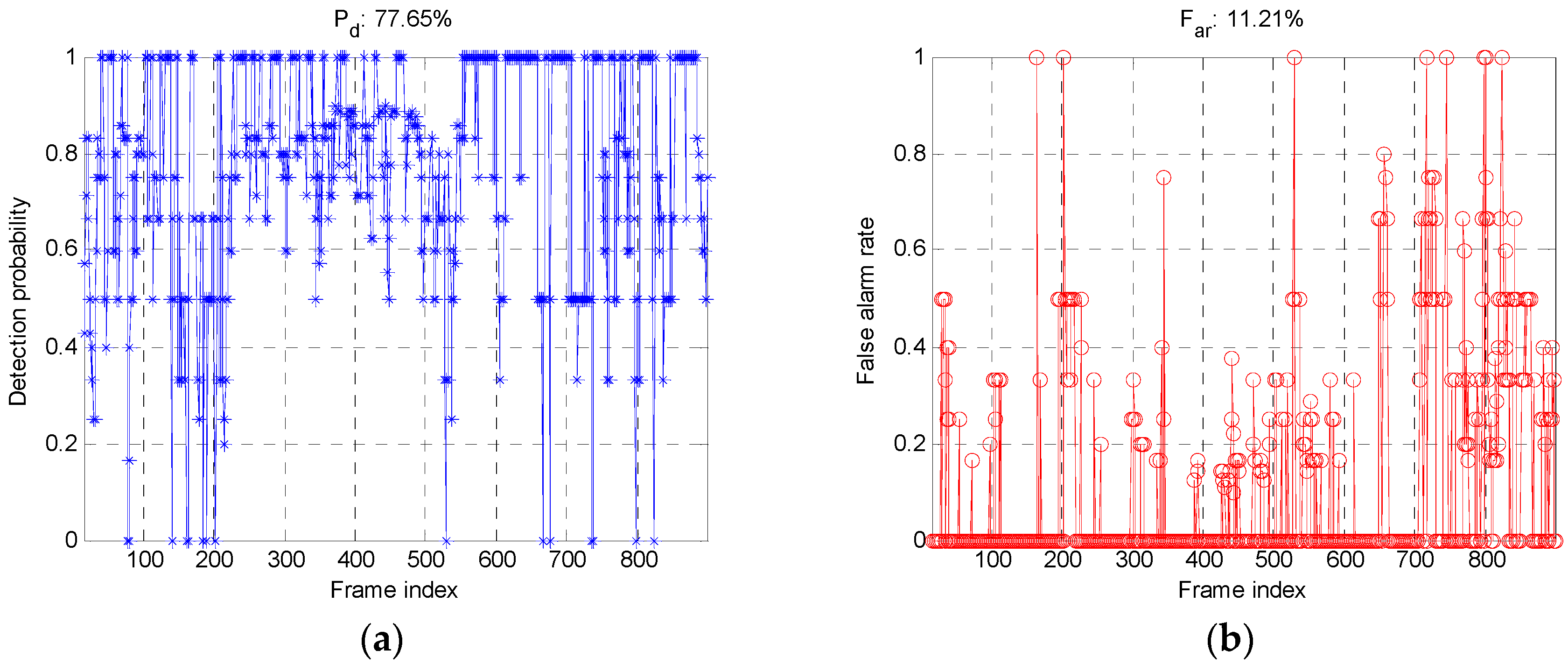
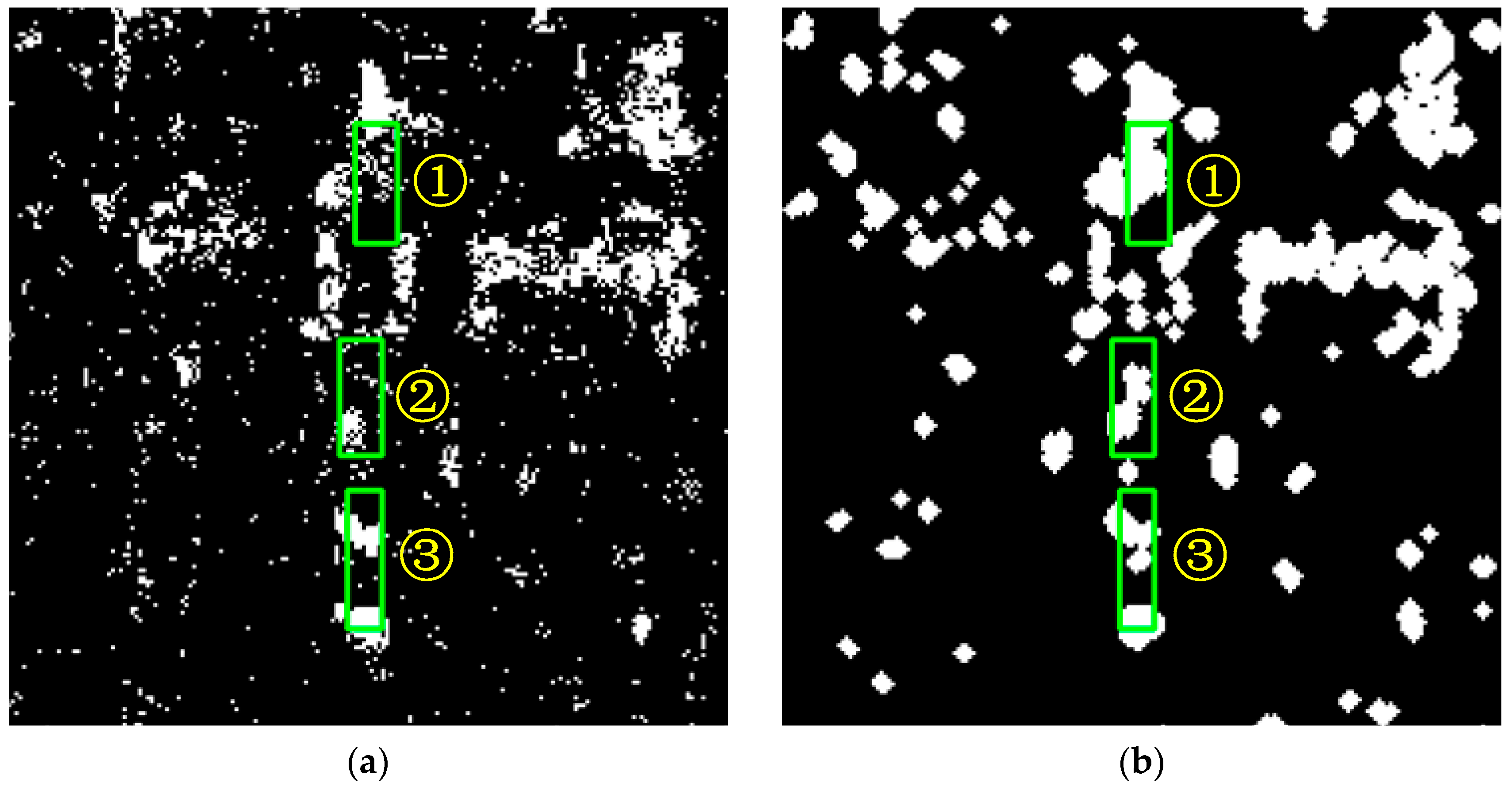
4.2. Results of Shadow Detection

The processing parameters were as follows: The grayscale range used for background frame detection ( C m i n ,   C m a x ) was (30, 50), T R O I was set to 1.3, and N was set to 7 based on the analysis in Section 3. The area of ROI was limited to the range (80, 500). The morphological opening operation used a 3 × 3 circular structural element. The closed operation used a 5 × 5 circular structural element. Adaptive histogram equalization was used to improve visibility (the original video was extremely dark and objects in it were difficult to recognize).
Figure 6 and Figure 7 show that the background frame detection algorithm could extract regions that satisfied the grayscale range-related criteria of the moving target, while generating a large number of false alarms (see Figure 6b and Figure 7b). The multi-interval frame difference algorithm could detect regions of vibrations (see Figure 6c and Figure 7c). A comparison of the results of these two algorithms yielded a precise difference between false alarms and shadows of the real target (note the grayscale of each pixel; a false alarm could meet the grayscale criteria without variation), shown in Figure 6d and Figure 7d. The results of fusion are shown in Figure 6e and Figure 7e, and the final MTD result is depicted in Figure 6f and Figure 7f, marked with the green rectangles. Meanwhile, compared with Figure 5b, a false alarm detection was found in the lower left corner in Figure 7f.
The probability of detection P d and false alarm rate F a r were used to evaluate the detection performance of the proposed method. P d and F a r are defined as follows:
P d = N c N r × 100 %
F a r = N f N a l l × 100 %
where N c denotes the number of correct instances of detection and N r denotes the number of real moving targets. N f represents the number of false alarms and N a l l represents the number of all detected targets.
Figure 8 shows indices of the probability of detection and false alarm rate. Both P d and F a r yielded suitable values of 77.65% and 11.21%, respectively. Table 1 compares detection-related performance of the background frame detection algorithm, the multi-interval frame difference algorithm and the proposed algorithm. It is clear that the background frame detection algorithm recorded the highest rate of detection and the highest false alarm rate. The multi-interval frame difference algorithm yielded lowest false alarm rate but also a low rate of detection. The proposed algorithm, by combining the advantages of these two algorithms, yielded good results on both indices.

4.3. Comparison and Discussion

To visually show the effects of the background frame detection algorithm and the multi-interval frame difference algorithm, part of the target region is illustrated in Figure 9. The background frame detection algorithm could not deal with false alarms in a low-RCS background, whereas the multi-interval frame difference algorithm could not handle problems such as the misalignment and fracture of the detection box. The fusion algorithm, however, obtained satisfactory results in terms of both measures.
To verify the advantage of the multi-interval frame difference algorithm, it was compared with the conventional frame difference method (adjacent frame difference mentioned in Section 2). Three targets were marked in descending order of velocity from 1 to 3. The multi-interval frame difference algorithm outperformed the conventional method, as shown in Figure 10. In Figure 10a, only small areas of targets 1 and 2 are detected and deviated away from their real positions. By contrast, the result of detection in Figure 10b is superior.

4.4. Algorithm Time Complexity Analysis

In this subsection, we theoretically analyze the computational burden of the proposed algorithm by computing the floating-point operations (FLOPs) of the main steps. Assume the size of a frame of an image is P × Q (pixel × pixel). The image is real data. The calculation complexity of addition, subtraction, multiplication and logical operations of a frame of the image is P Q FLOPs. Then, the computational complexity of Equations (4)–(6) and (10)–(11) can be expressed as:
C p = P Q + P Q 3 N + P Q + P Q + P Q + P Q = ( 3 N + 5 ) P Q
Since N is much smaller than P and Q, the computational complexity is O ( P Q ) . In addition, considering the frame rate of VideoSAR is f r a t e , the calculation burden of VideoSAR per second can be obtained as:
C p 1 = f r a t e C p = f r a t e ( 3 N + 5 ) P Q
In this paper, f r a t e is 29.97 Hz, P is 720 pixels, Q is 650 pixels and N was set to 7; the calculation amount of video SAR detection part is about 3.6 × 10⁸ FLOPs per second.
The proposed algorithm was tested in C language on a platform with an Intel i7–7700 K CPU with a dominant frequency of 4.2 GHz and 32 GB RAM. The running time of the detection algorithm part is 24.81 s, which is less than the whole video acquisition time of 30 s. The algorithm has high computational efficiency and meets the needs of practical application.

5. Conclusions

In light of the problem of the misalignment of the detection box, and a mismatch between the difference intervals and the target velocities, this paper combined the background frame detection algorithm and the multi-interval frame difference algorithm to improve performance in terms of MTD, especially in the case of a slowly moving target. To solve the problem whereby the conventional frame difference algorithm cannot detect the target at different velocities, the proposed algorithm accumulated the results of differences among multiple frames to improve MTD of a slowly moving target. To solve the problem whereby the detection boxes obtained via difference-based algorithms were misaligned and fractured, the proposed algorithm introduced background frame detection to obtain accurate positions of the shadow and used the result of multi-interval frame difference to reduce false alarms, while preserving the correct target. The results of experiments on empirically acquired VideoSAR data verified the effectiveness of the proposed algorithm. The algorithm can also be applied to point moving target detection of optical video satellites (such as Jilin No. 1 Video Satellite).

Author Contributions

All the authors made significant contributions to the work. Z.H. and Z.L. designed the research and analyzed the results. X.C. and T.Y. performed the experiments. Z.H. and Z.L. wrote the paper. A.Y. and Z.D. provided suggestions for the preparation and revision of the paper. All authors have read and agreed to the published version of the manuscript.

Funding

This research received no external funding.

Data Availability Statement

The data presented in this study are available on request from the corresponding author.

Acknowledgments

The authors would like to thank the Sandia National Laboratory (SNL) for providing the real Video Synthetic Aperture Radar (VideoSAR) data and the National University of Defense Technology for supporting the research.

Conflicts of Interest

The authors declare no conflict of interest.

References

  1. Xiang, D.; Wang, W.; Tang, T.; Su, Y. Multiple-component polarimetric decomposition with new volume scattering models for PolSAR urban areas. IET Radar Sonar Navig. 2017, 11, 410–419. [Google Scholar] [CrossRef]
  2. Wang, W.; An, D.; Luo, Y.; Zhou, Z. The Fundamental Trajectory Reconstruction Results of Ground Moving Target from Single-Channel CSAR Geometry. IEEE Trans. Geosci. Remote Sens. 2018, 56, 1–11. [Google Scholar] [CrossRef]
  3. Dudczyk, J.; Kawalec, A. Optimizing the minimum cost flow algorithm for the phase unwrapping process in SAR radar. Bull. Pol. Acad. Sci. Tech. Sci. 2014, 62, 511–516. [Google Scholar] [CrossRef] [Green Version]
  4. Lin, C.; Tang, S.; Zhang, L.; Guo, P. Focusing High-Resolution Airborne SAR with Topography Variations Using an Extended BPA Based on a Time/Frequency Rotation Principle. Remote Sens. 2018, 10, 1275. [Google Scholar] [CrossRef] [Green Version]
  5. Kim, S.-W.; Won, J.-S. Acceleration Compensation for Estimation of Along-Track Velocity of Ground Moving Target from Single-Channel SAR SLC Data. Remote Sens. 2020, 12, 1609. [Google Scholar] [CrossRef]
  6. Tanveer, H.; Balz, T.; Cigna, F.; Tapete, D. Monitoring 2011–2020 traffic patterns in Wuhan (China) with COSMO-SkyMed SAR, amidst the 7th CISM military world games and COVID-19 outbreak. Remote Sens. 2020, 12, 1636. [Google Scholar] [CrossRef]
  7. Cerutti-Maori, D.; Sikaneta, I. A Generalization of DPCA Processing for Multichannel SAR/GMTI Radars. IEEE Trans. Geosci. Remote Sens. 2013, 51, 560–572. [Google Scholar] [CrossRef]
  8. Budillon, A.; Schirinzi, G. Performance evaluation of a GLRT moving target detector for TerraSAR-X along-track interferometric data. IEEE Trans. Geosci. Remote Sens. 2015, 53, 3350–3360. [Google Scholar] [CrossRef]
  9. Ender, J.H.G.; Gierull, C.H.; Cerutti-Maori, D. Improved Space-Based Moving Target Indication via Alternate Transmission and Receiver Switching. IEEE Trans. Geosci. Remote Sens. 2008, 46, 3960–3974. [Google Scholar] [CrossRef]
  10. Harmony, D.W.; Bickel, D.L.; Martinez, A.; Martinez, A. A Velocity Independent Continuous Tracking Radar Concept; Sandia National Lab.: Monterey, CA, USA, 2011. [Google Scholar]
  11. He, Z.; Chen, X.; Yi, T.; He, F.; Dong, Z.; Zhang, Y. Moving Target Shadow Analysis and Detection for ViSAR Imagery. Remote Sens. 2021, 13, 3012. [Google Scholar] [CrossRef]
  12. Yang, X.; Shi, J.; Zhou, Y.; Wang, C.; Hu, Y.; Zhang, X.; Wei, S. Ground Moving Target Tracking and Refocusing Using Shadow in Video-SAR. Remote Sens. 2020, 12, 3083. [Google Scholar] [CrossRef]
  13. Tian, X.; Liu, J.; Mallick, M.; Huang, K. Simultaneous Detection and Tracking of Moving-Target Shadows in ViSAR Imagery. IEEE Trans. Geosci. Remote Sens. 2021, 59, 1182–1199. [Google Scholar] [CrossRef]
  14. Zhao, B.; Han, Y.; Wang, H.; Tang, L.; Liu, X.; Wang, T. Robust Shadow Tracking for Video SAR. IEEE Geosci. Remote Sens. Lett. 2021, 18, 821–825. [Google Scholar] [CrossRef]
  15. Jahangir, M. Moving target detection for synthetic aperture radar via shadow detection. In Proceedings of the IET International Conference on Radar Systems 2007; Institution of Engineering and Technology: Edinburgh, UK, 2007; pp. 16–18. [Google Scholar]
  16. Zhang, Y.; Mao, X.; Yan, H.; Zhu, D.; Hu, X. A novel approach to moving targets shadow detection in VideoSAR imagery sequence. In Proceedings of the 2017 IEEE International Geoscience and Remote Sensing Symposium (IGARSS); Institute of Electrical and Electronics Engineers (IEEE): Fort Worth, TX, USA, 2017; pp. 606–609. [Google Scholar]
  17. Wang, H.; Chen, Z.; Zheng, S. Preliminary Research of Low-RCS Moving Target Detection Based on Ka-Band Video SAR. IEEE Geosci. Remote Sens. Lett. 2017, 14, 811–815. [Google Scholar] [CrossRef]
  18. Liu, Z.; An, D.; Huang, X. Moving Target Shadow Detection and Global Background Reconstruction for VideoSAR Based on Single-Frame Imagery. IEEE Access 2019, 7, 42418–42425. [Google Scholar] [CrossRef]
  19. Wen, L.; Ding, J.; Loffeld, O. Video SAR Moving Target Detection Using Dual Faster R-CNN. IEEE J. Sel. Top. Appl. Earth Obs. Remote Sens. 2021, 14, 2984–2994. [Google Scholar] [CrossRef]
  20. Chen, H.; Zhang, F.; Tang, B.; Yin, Q.; Sun, X. Slim and Efficient Neural Network Design for Resource-Constrained SAR Target Recognition. Remote Sens. 2018, 10, 1618. [Google Scholar] [CrossRef] [Green Version]
  21. Li, Z.; Yu, A.; Dong, Z.; He, Z.; Yi, T. Suppressing False Alarm in VideoSAR viaGradient-Weighted Edge Information. Remote Sens. 2019, 11, 2677. [Google Scholar] [CrossRef] [Green Version]
  22. Culibrk, D.; Marques, O.; Socek, D.; Kalva, H.; Furht, B. Neural Network Approach to Background Modeling for Video Object Segmentation. IEEE Trans. Neural Netw. 2007, 18, 1614–1627. [Google Scholar] [CrossRef]
  23. Yuan, Y.; Guojin, H.E.; Wang, G.; Jiang, W.; Kang, J. A background subtraction and frame subtraction combined method for moving vehicle detection in satellite video data. J. Univ. Chin. Acad. Sci. 2018, 35, 50–58. [Google Scholar]
  24. Li, Z.; Dong, Z.; Yu, A.; He, Z.; Zhu, X. A Robust Image Sequence Registration Algorithm for Videosar Combining Surf with Inter-Frame Processing. In Proceedings of the IGARSS 2019-2019 IEEE International Geoscience and Remote Sensing Symposium; Institute of Electrical and Electronics Engineers (IEEE), Yokohama, Japan, 28 July–2 August 2019; pp. 2794–2797. [Google Scholar]
Figure 1. Principle of shadow extraction of difference-based MTD algorithms. (a) Principle of background difference. (b) Principle of frame difference. The blue rectangles represent frames.
Remotesensing 13 03291 g001
Figure 2. Schematic diagram of the proposed algorithm. The gray rectangles represent the shadow of the moving target, the gray circles represent false alarms from a low-RCS background, and the red dashed lines represent the detection boxes. (a) Results of background frame detection. (b) Results of multi-interval frame difference. (c) Result of fusion and threshold determination.
Remotesensing 13 03291 g002
Figure 3. Flowchart of the proposed VideoSAR-based MTD algorithm. The green box represents the background frame detection step, the orange box represents the multi-interval frame difference step, and the blue box represents the fusion and threshold determination step.
Remotesensing 13 03291 g003
Figure 4. Results of marking of moving cars in the SNL VideoSAR data. (a) Number of moving cars. (b) Motion of moving cars.
Remotesensing 13 03291 g004
Figure 5. Results of detection of the shadow of a moving target on the ground in SNL VideoSAR data. The yellow rectangles highlight the shadow of the marked moving car. (a) The 23rd frame. (b) The 551st frame.
Remotesensing 13 03291 g005
Figure 6. The results of processing of the 23rd frame. The green rectangles highlight the detected moving targets. (a) Results of preprocessing. (b) Results of background frame detection. (c) Results of multi-interval frame difference. (d) Results of fusion. (e) Results of false alarm suppression. (f) Final MTD results.
Remotesensing 13 03291 g006aRemotesensing 13 03291 g006b
Figure 7. The results of processing of the 551st frame. The green rectangles highlight the detected moving targets. (af) correspond to those in Figure 6a–f.
Remotesensing 13 03291 g007
Figure 8. Statistics on detection-related performance of the proposed algorithm. (a) Detection rate. (b) False alarm rate.
Remotesensing 13 03291 g008
Figure 9. Comparison between the background frame detection algorithm and the multi-interval frame difference algorithm. The green rectangles represent the real position of the shadow of the moving target. (a) Result of the background frame detection algorithm. (b) Result of the multi-interval frame difference algorithm.
Remotesensing 13 03291 g009
Figure 10. Comparison between the multi-interval frame difference algorithm and the conventional frame difference algorithm. The green rectangles represent the real position of the shadow of the moving target. (a) Result of conventional frame difference. (b) Result of multi-interval frame difference.
Remotesensing 13 03291 g010
Table 1. Comparison of detection-related performance of three algorithms.
IndicesFrame NumberBackground Frame Detection AlgorithmMulti-Interval Frame Difference AlgorithmProposed Algorithm
Detection rate50100%3/5 60%4/5 80%
150100%100%100%
250100%2/6 33.3%100%
3506/7 85.7%3/7 42.9%5/7 71.4%
450100%2/5 40%4/5 80%
550100%1/5 20%100%
650100%2/5 40%100%
750100%2/5 40%100%
850100%1/4 25%3/4 75%
False alarm rate5025/30 83.3%2/5 40%0
15014/18 77.8%00
25026/32 81.3%01/7 14.3%
35030/38 78.9%01/7 14.3%
45019/24 79.2%01/5 20%
55016/21 76.2%1/2 50%0
65014/19 73.7%00
75024/29 82.8%00
85016/20 80%00
Publisher’s Note: MDPI stays neutral with regard to jurisdictional claims in published maps and institutional affiliations.

