Article

A Time-Domain Simulation System of MICAP L-Band Radiometer for Pre-Launch RFI Processing Study

1
The School of Electronic, Electrical and Communication Engineering, University of Chinese Academy of Sciences, Beijing 100049, China
2
The Key Laboratory of Microwave Remote Sensing, National Space Science Center, Chinese Academy of Sciences, Beijing 100190, China
*
Author to whom correspondence should be addressed.
Remote Sens. 2021, 13(16), 3230; https://doi.org/10.3390/rs13163230
Submission received: 3 July 2021 / Revised: 31 July 2021 / Accepted: 11 August 2021 / Published: 14 August 2021
(This article belongs to the Special Issue New Technologies for Earth Remote Sensing)

Abstract

:
Microwave Imager Combined Active and Passive (MICAP), which is a package of active and passive microwave instruments including L/C/K-band radiometers and L-band scatterometer, has been approved to be taken onbord the Chinese Ocean Salinity Mission. The L-band one-dimensional synthetic aperture radiometer (L-Rad) is the key part of MICAP to measure sea surface salinity (SSS). Since radio frequency interference (RFI) is reported as a serious threat to L-band radiometry, the RFI detection and mitigation techniques must be carefully designed before launch. However, these techniques need to be developed based on the knowledge of how RFI affects complex correlation, visibility function, and reconstructed brightness temperature. This paper presents a time-domain signal modeling method for the simulation of interferometric measurement under RFI’s presences, and a simulation system for L-Rad is established accordingly. Several RFI cases are simulated with different RFI types, parameters, and positions; and the RFI characteristics upon L-Rad’s measurement are discussed. The proposed simulation system will be further dedicated to the design of RFI processing strategy onboard MICAP.

1. Introduction

Sea surface salinity (SSS) plays an important role in energy exchange between the ocean and atmosphere. SSS is also a key parameter for tracking the global water cycle and global climate change. It is theoretically feasible to measure SSS by L-band (1.4–1.427 GHz) radiometry, because it features a sufficient sensitivity of radiometric measurements to the change of salinity in oceans [1,2]. Until recently, three satellite missions have been launched to measure SSS, including SMOS [3], Aquarius/SAC-D [4], and SMAP [5]. The Microwave Imager Combined Active and Passive (MICAP) [6,7] is one of the primary payloads of Chinese Ocean Salinity Mission. It has the capability of L/C/K multi-band passive and L-band active measurements, and can simultaneously retrieve sea surface salinity (SSS), sea surface temperature (SST), and wind speed (WS).
Radio frequency interference (RFI) signals are unwanted electromagnetic emissions that degrade the performance of a receiver, which generally introduces an offset in the reconstructed brightness temperature and thus, hampering the retrieval of geophysical parameters. As the electromagnetic spectrum becomes increasingly crowded, X-band [8], C-band [9], and K-band [10] space-borne passive microwave remote sensors have been reported to be affected by RFI. L-band instruments are especially sensitive to RFI, as issued by SMOS [11,12], SMAP [13,14], and Aquarius [15]. It can be foreseen that MICAP will encounter RFI contaminations unavoidably, and it is imperative to design RFI detection and mitigation strategy for the radiometers of MICAP.
SMOS does not utilize any dedicated hardware to detect and mitigate RFI in orbit. Many on-ground processing methods have been developed for the RFI detection and mitigation, including the DOA estimation method [16,17], the subspace method [18], the visibility-domain method [19], and so on, to detect and mitigate RFI. An important feature of the Aquarius approach to RFI processing strategy is rapid sampling [20]. The fundamental sample period of Aquarius is 10 ms, far less than the Nyquist rate (more than 5 s). Thus, many samples can be obtained in the time it takes for the radiometer to move one-half the width of its along-track footprint. Moreover, an on-ground time-domain RFI detection and mitigation method [21] is adopted by Aquarius. SMAP is the first mission to include a complex digital backend in spaceborn microwave radiometer system, which enables additional RFI detection and mitigation capabilities in spectral and statistical domain, together with on-ground processing [22,23]. CubeRRT [24] has the capability of real-time on-board detection and mitigation of RFI. CubeRRT adopts spectral and statistical domain methods similar to SMAP [25]. Most of the existing studies on RFI detection and mitigation aim on real aperture radiometers [26]. Only a few works target on synthetic aperture radiometes [27].
The L-band radiometer of MICAP is a one-dimensional synthetic aperture radiometer (L-Rad). L-Rad plans to process RFI with the time-domain, frequency-domain, and space-domain methods. To avoid the full-band data products with long integration time being contaminated by RFI, the rapid sampling using a 10-ms integration time and the spectral filtering dividing full-band into thirteen sub-band (2-MHz bandwidth) are employed by L-Rad. After removing those rapidly sampled sub-band samples identified as RFI, the remaining samples are averaged to build data products. However, due to the conflict between the huge transmission data volume and the limited downlink bandwidth, it is impossible to transmit all rapidly sampled sub-band data products to the ground. Thus, it is essential to develop in-orbit RFI processing strategy. For instance, the data anomaly that larger than three units of sensitivity (either at correlation level, or brightness temperature level) is marked as RFI contamination. Those labeled data is discarded after multi-domain decision, and the potentially remained RFI is left for the on-ground processing. RFI detection and mitigation are especially difficult for the synthetic aperture radiometers. Since the 3-dB beamwidth of each element antenna must cover the alias-free field of view (AF-FOV), the RFI sources are more likely to be captured by the antennas. This feature generally results in a lower antenna gain, making it difficult to detect RFI in temporal domain [26]. In addition, the complex correlation measured by the synthetic aperture radiometer is usually realized by calculating the cross power of low-resolution quantized baseband IQ sampled signals, which reduces the interference to noise power ratio (INR) and further increases the difficulty of RFI detection.
The instrument data products of MICAP L-Rad include complex correlation, calibrated visibility function, and reconstructed brightness temperature. How RFI affects those data products is extremely important to the proper design of RFI detection and mitigation strategy. In general, the simulation for synthetic aperture radiometers is based on the Fourier relationship between the brightness temperature and visibility function [28,29]. However, this kind of simulation is not suitable for RFI study, since it does not have the capability to depict the temperal and spectral features of different RFI signals. To study how RFI affects the data products of MICAP L-Rad and design in-orbit RFI detection and mitigation methods, a time-domain simulation system that emulates entire receiving chain of MICAP L-Rad is proposed accordingly. The simulation system is established following the specific configuration of MICAP L-Rad, and the RFI signals are modeled at IF stage for reducing the computational complexity of the simulation system.
This paper is organized as follows. The system design of MICAP L-Rad is presented in Section 2, including hardware configuration, digital subsystem, and the preliminary in-orbit RFI processing strategy. In Section 3, a time-domain signal modeling is proposed for the simulation of MICAP L-Rad. Several RFI cases are simulated and discussed in Section 4, and the basic RFI characteristics observed by MICAP L-Rad are summarized.

2. System Architecture of MICAP/L-Rad

MICAP is a package of active and passive microwave instruments including L/C/K-band radiometers and L-band scatterometer. Both active and passive instruments of MICAP share a parabolic cylindrical reflector, as shown in Figure 1a. Passive instruments consist of three one-dimensional synthetic aperture radiometers that operate in L-band, C-band, and K-band, respectively (L/C/K-Rad). As the antenna elements are aligned to be perpendicular to the satellite flight direction, a cross-track synthetic aperture is realized, resulting in a swath width that larger than 950 km. Figure 1b shows the observation schematic diagram of MICAP. The main specifications of L/C/K-Rad are shown in Table 1. The L-Rad maps global SSS, and the C/K-Rad measure SST. The active instrument is an L-band digital beam forming scatterometer (L-SCAT) for WS measurement. SST and WS are used to improve the accuracy of SSS retrieval.

2.1. MICAP L-Rad System

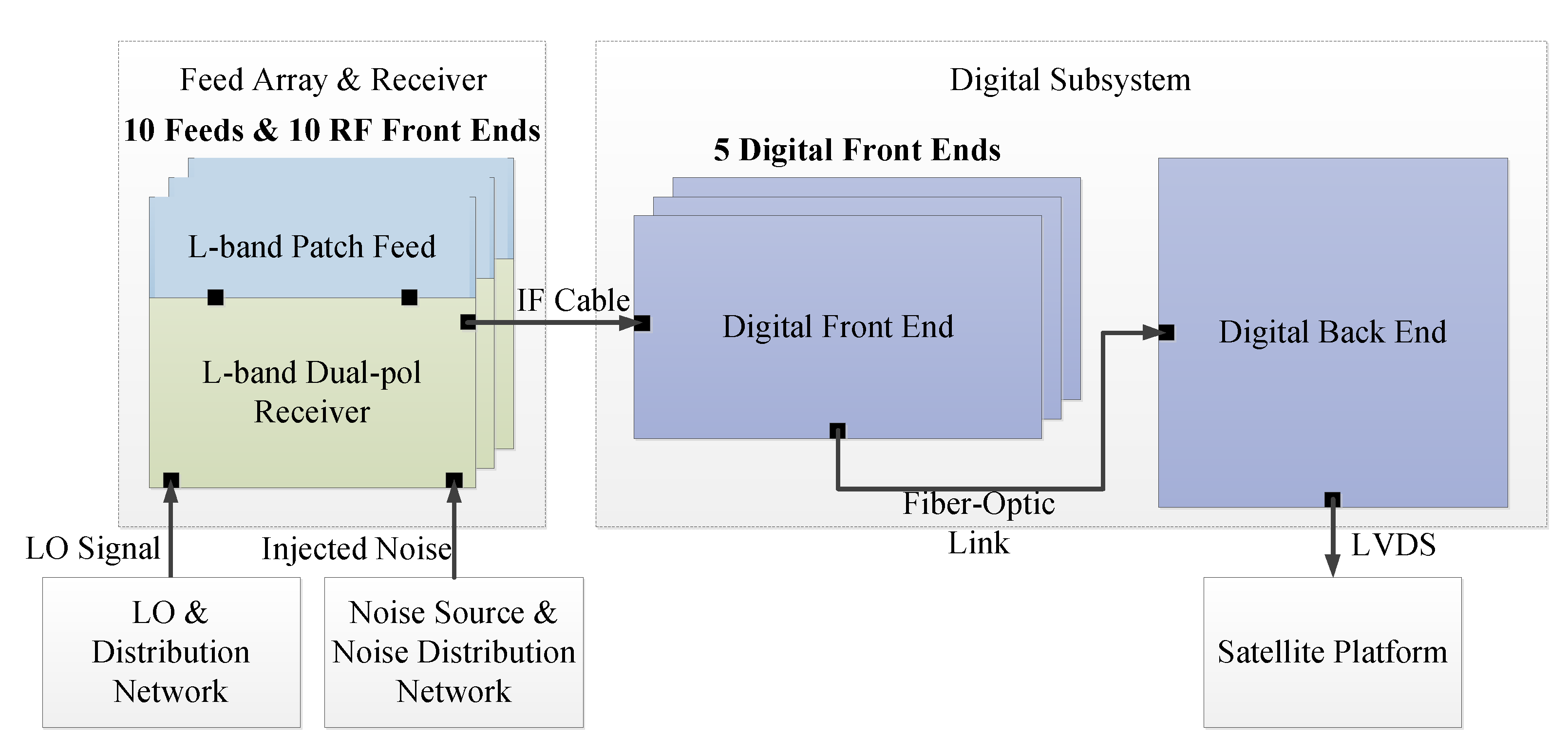
L-Rad measures the visibility function [30] of the obsevation scene at L-band, that is, the correlation coefficient between the signal received by every two antenna feeds, as well as the system equivalent noise temperature of each receiver. As shown in Figure 2, the MICAP L-Rad system consists of 10 H/V polarized antenna feeds, 10 L-band receivers, 5 digital front ends, and a digital back end.
There are 10 antenna feeds in L-Rad, and they are arranged in the layout shown in Figure 3. The minimum antenna feed spacing ( Δ u ) is 0.6125 λ , where λ is the wavelength of central frequency (1413 MHz). There are a total of 23 non-redundant correlation baselines in L-Rad whose lengths are linearly distributed as l Δ u ( l 0 , 1 , , 22 ). The extent of AF-FOV in direction cosine is ξ [ 0.6171 , 0.6171 ] , which is calculated by 1 / Δ u 1 .
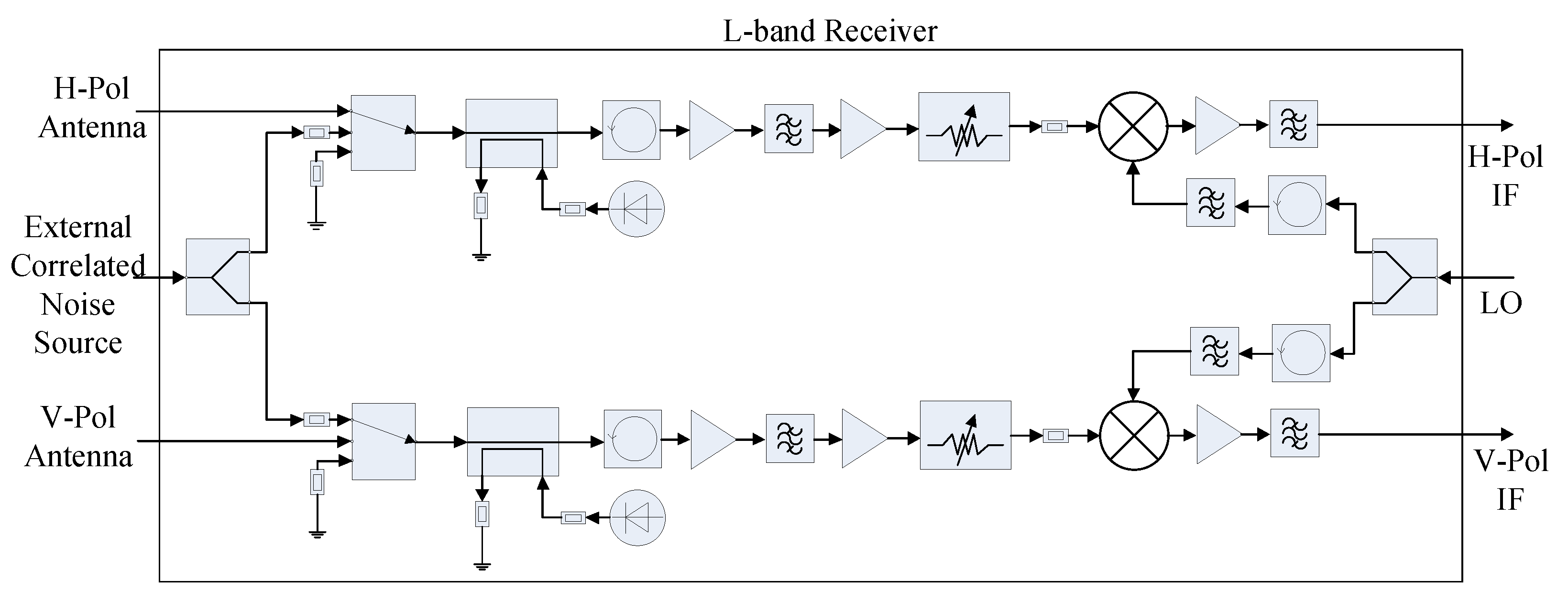
The L-band receiver is a dual-polarization noise injection microwave radiometer receiver [31]. The primary function of the L-band receiver is to implement calibration, amplify and filter RF signal, and shift RF signal to IF signal. As shown in Figure 4, each polarization channel of the L-band receiver contains an RF switch that selects antenna, matched load, or correlated noise source. Real-time calibration can be realized by injecting the two-level correlated noise and uncorrelated noise. The receiver shifts the RF signal, which centered at 1413.5 MHz with 25-MHz bandwidth, to IF signal with single sideband down-conversion. The LO frequency is 1319 MHz. Thus, the IF signal to be sample by the digital front end is 94 ± 12.5 MHz.

2.2. Digital Subsystem

The primary function of the digital subsystem is to shift IF signal to baseband IQ signal, divide the full-band signal into 13 sub-band IQ signals, calculate the complex correlation between each channel of sub-band IQ signal as well as the variance of each channel of the sub-band IQ signal. In addition, the in-orbit RFI detection and mitigation methods are also implemented in the digital subsystem. As mentioned before, the correlation coefficient and system equivalent noise temperature are derived from these data products generated by the digital subsystem. Figure 5 shows the block diagram of the digital subsystem, which consists of 5 digital front ends and a digital back end.

2.2.1. Digital Front End

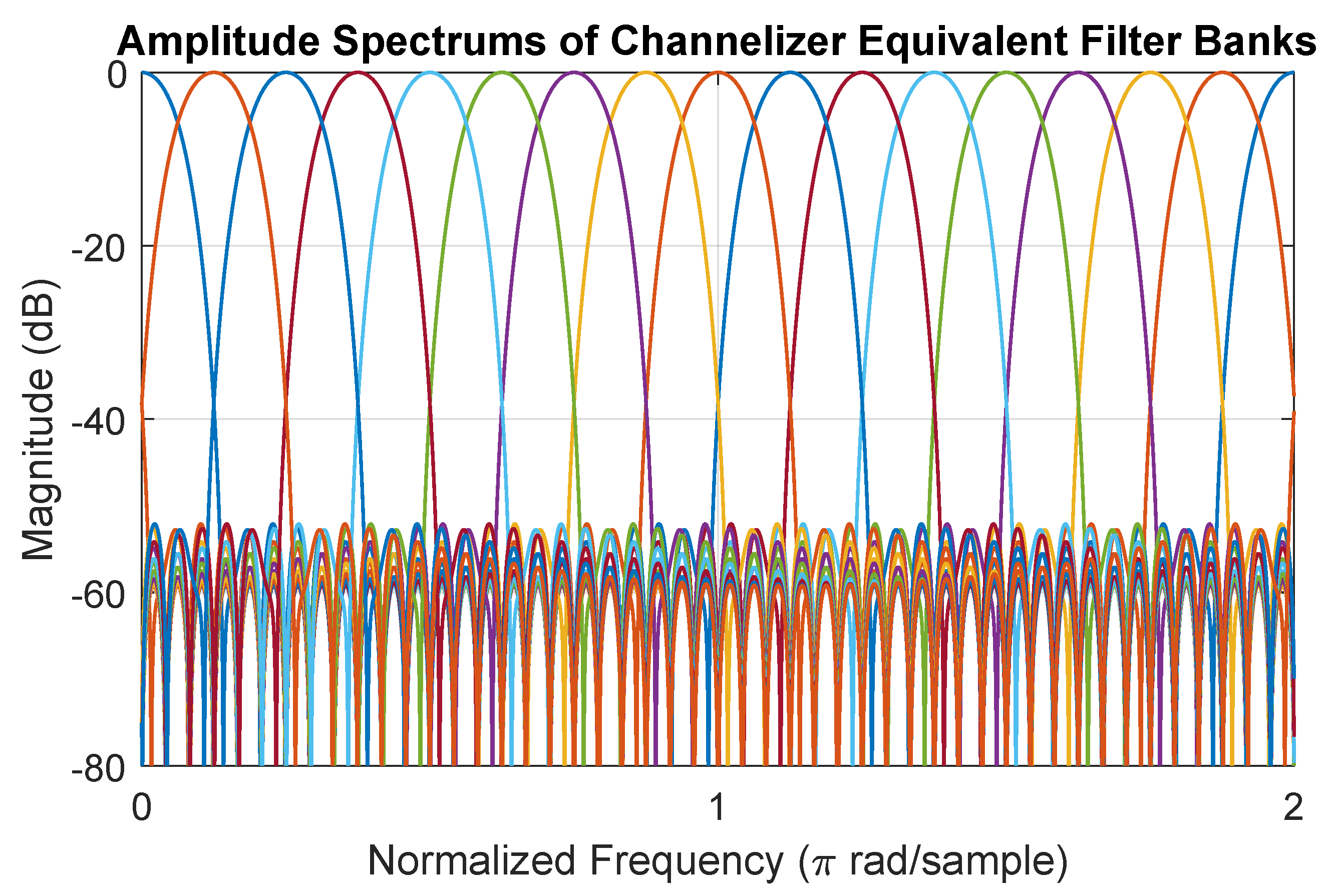
Each digital front end processes 2 pairs of H/V-polarization IF channels, and divides the full-band signal into 13 sub-band signals. In this way, a time-frequency RFI detection and mitigation method can be implemented. Furthermore, calculating the variance of sub-band signal is used to calibrate the system equivalent noise temperature. The IF signals input to the digital front end are sampled by two dual-channel 8-bit ADCs with a sampling rate of 125 MSaps after signal conditioning. The carrier frequency of digital IF signals is 31 MHz. A FPGA implements digital signal processing with 4 identical DSP processors, which consists of a digital down-converter (DDC), channelizer, 3-level digitizer, and auto-correlator. DDC shifts the IF signal to the baseband IQ signal. DDC consists of a digital quadrature down-converter using the technique presented in [32], a 47th-order Blackman low-pass FIR filter to eliminate the image spectrum, and a one-forth decimator to reduce the data rate of the baseband IQ signal to 31.25 MSaps. Channelizer uses the polyphase channelized receiver technique [33] to evenly divide baseband IQ signals into 16 frequency channels. The channelizer is equivalent to a filter bank, whose amplitude spectrum is showed in Figure 6. The 3-dB bandwidth of these equivalent filters is 2 MHz. The 25-MHz IF full-band signal occupies 13 frequency channels. A one-eighth decimator is used to reduce these sub-band IQ signals’ data rate to 3.91 MSaps. These sub-band IQ signals are digitized to 3-level digitized signals before correlation to balance hardware resource consumption and the loss of sensitivity [34]. The quantization threshold of different frequency channels is updated in real-time to achieve an optimal sensitivity [35]. The auto-correlator calculates each multi-level sub-band IQ signal’s variance ( p i [ m , u ] ), which replaces the analog detector to calibrate the system equivalent noise temperature.
p i [ m , u ] = 1 N n = 0 N 1 y i [ n , m , u ] · y i [ n , m , u ] *
where N is the samples collected within 10-ms integration time; y i [ n , m , u ] is the multi-bit sub-band complex signal; [ n , m , u ] implies the time index ( n 0 , 1 , , N 1 ), sub-band index ( m 1 , 2 , , 13 ), and correlation baseline index ( u 0 , 1 , , 22 ), respectively; i is the antenna feed index of a correlation baseline. The communication between the digital front end and digital back end is realized by fiber transceivers. The data transmitted to the digital back end include 3-level sub-band IQ signals and multi-level sub-band IQ signal variances.

2.2.2. Digital Back End

The primary function of digital back end is to calculate the complex cross-correlation ( c i j [ m , u ] ) between each 3-level sub-band signal as well as the mean ( b i [ m , u ] ) and auto-correlation ( a i [ m , u ] ) of each 3-level sub-band signal with the following equations:
c i j [ m , u ] = 1 N n = 0 N 1 z i [ n , m , u ] · z j [ n , m , u ] * a i [ m , u ] = 1 N n = 0 N 1 z i [ n , m , u ] · z i [ n , m , u ] * b i [ m , u ] = 1 N n = 0 N 1 z i [ n , m , u ]
where z j [ n , m , u ] is 3-level sub-band complex signal. These data are used to calculate the correlation coefficient with the method given by [34].

2.3. In-Orbit RFI Detection and Mitigation Method

The RFI detection and mitigation method planned to use in MICAP L-Rad combines the time-domain method, frequency-domain method, and space-domain method. It is implemented in the digital back end. The data products built by MICAP L-Rad can be classified into two types, one is sub-band correlation, and another is sub-band reconstructed brightness temperature. The sub-band correlation can be described in three dimensions, including time domain, frequency domain, and correlation baseline domain. The sub-band reconstructed brightness temperature is also three-dimensional, including time domain, frequency domain, and space domain. The RFI detection is based on the outlier identification, and it is carried out within each data dimension in the first step. Then, these detection results are judged together in a decider to give out a final RFI detection result. Since the 3-level cross-correlation can not be averaged over the frequency domain. The RFI mitigation is implemented in the time domain, after in-orbit RFI mitigation, the sub-band correlation is averaged over the time domain to reduce the data rate of downlink. These sub-band correlation data are transmitted to the ground. It is essential for studying the in-orbit RFI detection and mitigation method to build an instrumental full-chain time-domain simulation system of MICAP L-Rad.

3. Instrumental Full-Chain Time-Domain Simulation System of MICAP L-Rad

The simulation system emulates how MICAP L-Rad works and is used to study how RFI impacts on the data products of MICAP L-Rad. For simplicity, time-domain signals are generated at IF stage directly and IF time-domain signals of each receiver are generated directly. The time-domain IF signal is considered as a combination of natural radiation and RFI. The complex correlation and reconstructed brightness temperature are obtained in the same way as described in MICAP L-Rad signal processing. These IF signals of natural radiation are modeled with correlated band-limited Gaussian noise signals under the visibility function constraints derived from the Corbella equation. RFI with different types, parameters, and positions can be set up in the simulation system, and how RFI affects the data products measured by MICAP L-Rad can be simulated.

3.1. Visibility Function Generation

Corbella equation [30] describes the relationship between brightness temperature distribution T B ( ξ , η ) and visibility function V i j ( u ) , it can be described as:
V i j ( u ) = ξ 2 + η 2 1 T i j ( ξ , η ) r ˜ ( u ξ f 0 ) e j 2 π u ξ d ξ d η T i j ( ξ , η ) = D i D j 4 π T B ( ξ , η ) T p h 1 ξ 2 η 2 F n i ( ξ , η ) F n i * ( ξ , η )
where
  • r ˜ ( u ξ f 0 ) is the so-called fringe washing function, which is determined by frequency response of the receivers forming the correlation baseline, and is negligible when the system bandwidth is small [36];
  • f 0 is the central frequency (1413.5 MHz for MICAP L-Rad);
  • ( ξ , η ) = ( sin θ cos ϕ , sin θ sin ϕ ) are direction cosine, and ( θ , ϕ ) are zenith angle and azimuth angle, respectively;
  • u = D x / λ is the normalized antenna spacing which represents correlation baseline length, and D x is the relative antenna spacing between every two antennas in the x-axis direction of a correlation baseline in x-axis direction;
  • i and j are antenna indexes;
  • F n i ( ξ , η ) and F n j ( ξ , η ) are the normalized antenna voltage patterns;
  • T p h is the physical temperature of the receiver, and is in units of K;
  • D i and D j are antenna directivities;
  • T i j ( ξ , η ) is the modified brightness temperature, and is in units of K;
The correlation coefficient measured by each correlation baseline is calculated by:
ρ θ ( u ) = V i j ( u ) T s y s i · T s y s j
where T s y s i is system equivalent noise temperature, and it can be described as [37]:
T s y s i = T A i + T r e c i
where T A i is antenna temperature measured by one antenna of a correlation baseline; T r e c i is the equivalent noise temperature of one receiver of a correlation baseline.

3.2. Time-Domain IF Signal Modeling of Natural Radiation

The time-domain IF signal of natural radiation is generated by the observation scene without RFI. These signals of natural radiation can be modeled by correlated band-limited Gaussian noise signals ( e 1 , 2 ( t ) ) constrained by system equivalent noise temperature ( T s y s ), bandwidth (B), carrier frequency ( f 0 ), and correlation coefficient ( ρ θ ). M correlated Gaussian noise signals are a set of linear combinations of M uncorrelated Gaussian noise signals. The linear transformation coefficients can be generated with the method in [38]. e 1 , 2 ( t ) can be generated in the following steps:

3.2.1. Baseband Uncorrelated Band-Limited Gaussian Noise Generation

Two uncorrelated band-limited Gaussian noise signals, a 1 ( t ) and a 2 ( t ) , with bandwidth B and carrier frequency f 0 , are generated. b 1 , 2 I , Q ( t ) are baseband IQ signals of a 1 , 2 ( t ) after quadrature down-conversion.

3.2.2. Linear Transformation Coefficient Generation

The linear transformation coefficients are derived from the correlation coefficient matrix ( W ) as below:
W = 1 0 ρ cos ( θ ) ρ sin ( θ ) 0 1 ρ sin ( θ ) ρ cos ( θ ) ρ cos ( θ ) ρ sin ( θ ) 1 0 ρ sin ( θ ) ρ cos ( θ ) 0 1
The linear transformation coefficient matrix ( Z ) is the Cholesky factorization matrix of W and is shown as below:
W = Z Z T Z = z 1 , 1 0 0 0 z 2 , 1 z 2 , 2 0 0 z 3 , 1 z 3 , 2 z 3 , 3 0 z 4 , 1 z 4 , 2 z 4 , 3 z 4 , 4
Each element in Z is the linear transformation coefficient used to generate correlated noise signals.

3.2.3. Baseband Correlated Band-Limited Gaussian Noise Generation

The baseband correlated band-limited Gaussian noise signals, c 1 , 2 I , Q ( t ) , with correlation coefficient ρ θ and bandwidth B, are generated as below:
c 1 I ( t ) = b 1 I ( t ) · z 1 , 1 c 1 Q ( t ) = b 1 I ( t ) · z 2 , 1 + b 1 Q ( t ) · z 2 , 2 c 2 I ( t ) = b 1 I ( t ) · z 3 , 1 + b 1 Q ( t ) · z 3 , 2 + b 2 I ( t ) · z 3 , 3 c 2 Q ( t ) = b 1 I ( t ) · z 4 , 1 + b 1 Q ( t ) · z 4 , 2 + b 2 I ( t ) · z 4 , 3 + b 2 Q ( t ) · z 4 , 4

3.2.4. Power Setup

d 1 , 2 I , Q ( t ) are derived from c 1 , 2 I , Q ( t ) by resetting the variance to T s y s B k Z / 2 , where Z is the impedance of the circuit, and k is the Boltzmann constant.

3.2.5. Quadrature Up-Conversion

e 1 , 2 ( t ) are derived from d 1 , 2 I , Q ( t ) after quadrature up-conversion to the carrier frequency of f 0 .

3.3. Time-Domain IF Signal Modeling of RFI

Common RFI sources in L-band can be classified into continue wave (CW) RFI, Chirp RFI, Pulse RFI, and spread-spectrum (SSC) RFI. Figure 7 shows the spectrograms of these RFI IF signals. The tunable parameters of these RFI sources at IF stage include:
  • CW: carrier frequency ( F c ), power ( P R F I I F );
  • Pulse: carrier frequency ( F c ), pulse repetition period ( T p u l s e ), duty cycle (d) and power ( P R F I I F );
  • Chirp: carrier frequency ( F c ), modulation period ( T c h i r p ), modulation bandwidth ( B c h i r p ) and power ( P R F I I F );
  • SSC: carrier frequency ( F c ), power ( P R F I I F ) and symbol rate (S);
Interference noise ratio (INR) describes the relative power of RFI at antenna reference plane and is defined as below:
I N R = T R F I A n t T B a v g T B a v g = 1 1 1 1 T B ( ξ , η ) d ξ d η
where T R F I A n t is the equivalent brightness temperature of RFI at the antenna reference plane; T B a v g is the average brightness temperature. The distance between the FOV center and satellite is about 755 km. According to the Friis transmission equation [39], the relationship between INR and the transmit power of an RFI source with an omnidirectional antenna is as below:
P R F I t x = T R F I A n t · k · B · ( 4 π L ) 2 λ 2 = T B a v g · k · B · I N R · ( 4 π L ) 2 λ 2 = I N R ( dB ) + 51.87 dBm
The parameters of remote sensors decide the gain and delay of RFI IF signal. The power of RFI IF signal P R F I I F is calculated by:
P R F I I F = | F i ( ξ R F I , η R F I ) | 2 · P R F I A n t = | F i ( ξ R F I , η R F I ) | 2 · T R F I A n t · B · k = | F i ( ξ R F I , η R F I ) | 2 · I N R · T B a v g · B · k
where | F i ( ξ , η ) | 2 represents the power pattern of the receiving antenna; ( ξ R F I , η R F I ) indicates the position of RFI source. The RFI IF signal phase of both antenna units of each correlation baseline are modeled as:
ϕ i = ϕ 0 + F i ( ξ R F I , η R F I ) ϕ j = ϕ 0 + F j ( ξ R F I , η R F I ) + 2 π f R F I τ τ = u ξ R F I + v η R F I f R F I
where f R F I is RFI frequency; ϕ 0 is initial phase; τ is time delay [36] between RFI wavefront arrival time of two antennas. Because the relative position between RFI source and satellite changes with time due to satellite flight, ( ξ R F I , η R F I ) is a function of time. However, satellite flies so fast that ( ξ R F I , η R F I ) could be considered as constant within a short period. Thus, the IF RFI signal arrived at antenna units could be modeled as x i , j ( t , u , v , ξ R F I , η R F I ) with the corresponding RFI parameters and remote sensor parameters.

3.4. Simulation System

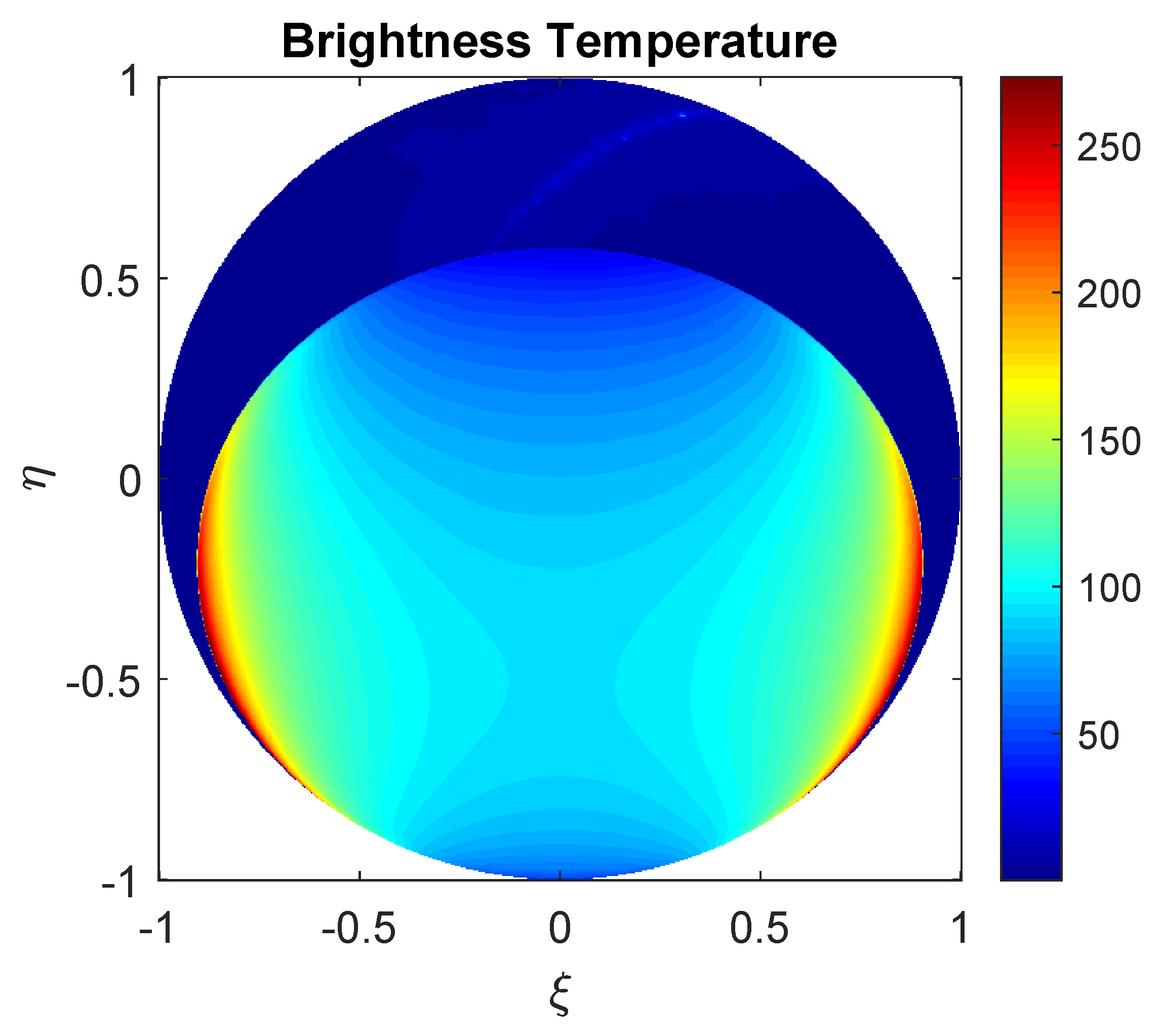
During the simlation, MICAP L-Rad is considered as a set of virtual correlation baselines with different lengths. The brightness temperature ( T B ( ξ , η ) ) of observation scene used to generate visibility function is a typical ocean scene [28], shown in Figure 8. Since the simulation system is established to study how RFI affects MICAP L-Rad, the gain differences and phase differences between different receivers are neglected. The simulation system works in observation mode and calibration mode, shown in Figure 9a,b, respectively. The signal processing of the simulation system is implemented in the baseband signal processing unit, and it is the same as the signal processing of MICAP L-Rad as mentioned in Section 2.2. When the simulation system works in calibration mode, T B ( ξ , η ) of observation mode is replaced with T B L ( ξ , η ) = 3 K (Cold sky) and T B H ( ξ , η ) = 300 K (Hot source) successively. The relationship between system equivalent noise temperature and multi-level auto-correlation is calibrated by the noise injected two-point calibration method. The calibrated system equivalent noise temperature ( T ^ s y s i , j [ m , u ] ) and correlation coefficient ( ρ θ ^ [ m , u ] ) derived from the correlation shown in (2) are used to calculate the calibrated visibility function ( V ^ [ m , u ] ).
A modified G-matrix method is applied to brightness temperature reconstruction of MICAP L-Rad [40]. Sub-band reconstructed brightness temperature ( T ^ B [ ξ , m ] ) is derived from sub-band calibrated visibility function V ^ [ m , u ] . Full-band data products, including full-band reconstructed brightness temperature ( T ^ B [ ξ ] ) and full-band calibrated visibility function ( V ^ [ u ] ), are calculated by averaging sub-band data products over the frequency domain.

3.5. Functional Verification of the Simulation System

The functional verification of the simulation system is conducted by Monte-Carlo simulation in the cases that RFI does not exist, and RFI does exist, respectively. The simulation system can be verified by comparing the statistics of simulator outputs with the MICAP L-Rad system specifications When RFI does not exist. When RFI exists, a two-dimensional sub-band reconstructed brightness temperature map contaminated by RFI is presented to implement the functional verification.
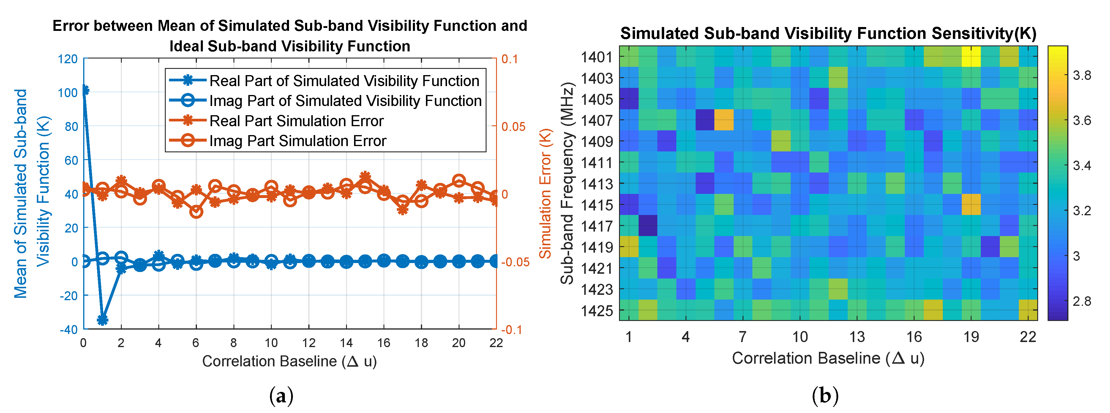
Figure 10a compares the ideal visibility function with the mean of the simulated sub-band visibility function generated from 100 Monte Carlo simulations. The absolute difference is no more than 0.02 K. The theoretical sensitivity of visibility function can be approximated by [36]:
Δ V T s y s i T s y s j B · τ
where the equivalent noise bandwidth of sub-band (B) is 2.08 MHz, and the equivalent integration time of 3-level correlation ( τ ) is 10/1.26 ms [35]. Thus, the theoretical sensitivity of the sub-band visibility function is about 3.17 K. Figure 10b shows the simulated sub-band visibility function sensitivity of 10-ms integration time calculated with 100 Monte Carlo simulation results.
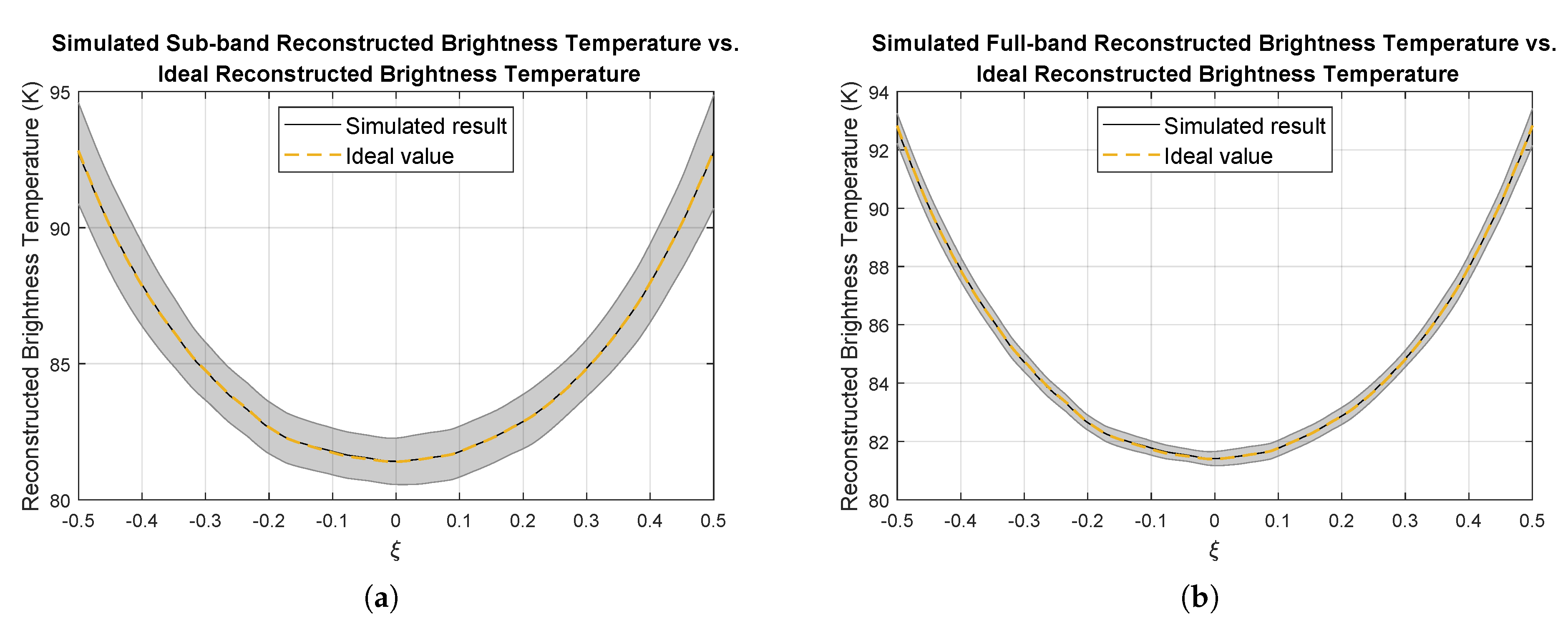
The full-band reconstructed brightness temperature and sub-band reconstructed brightness temperature of 1 s integration time within AF-FOV are presented in Figure 11a,b, respectively. The shade in the figure represents the sensitivity of simulated reconstructed brightness temperature. theoretical sensitivity of reconstructed brightness temperature can be approximated by [36]:
N E Δ T T s y s i T s y s j 2 B τ · ( 2 N b + 1 )
where N b is the length of the longest correlation baseline in unit of Δ u . The theoretical sensitivity of full-band reconstructed brightness temperature and sub-band reconstructed brightness temperature are 0.43 K and 1.51 K, respectively. The sensitivity of simulated reconstructed brightness temperature is consistent with the system configurations.
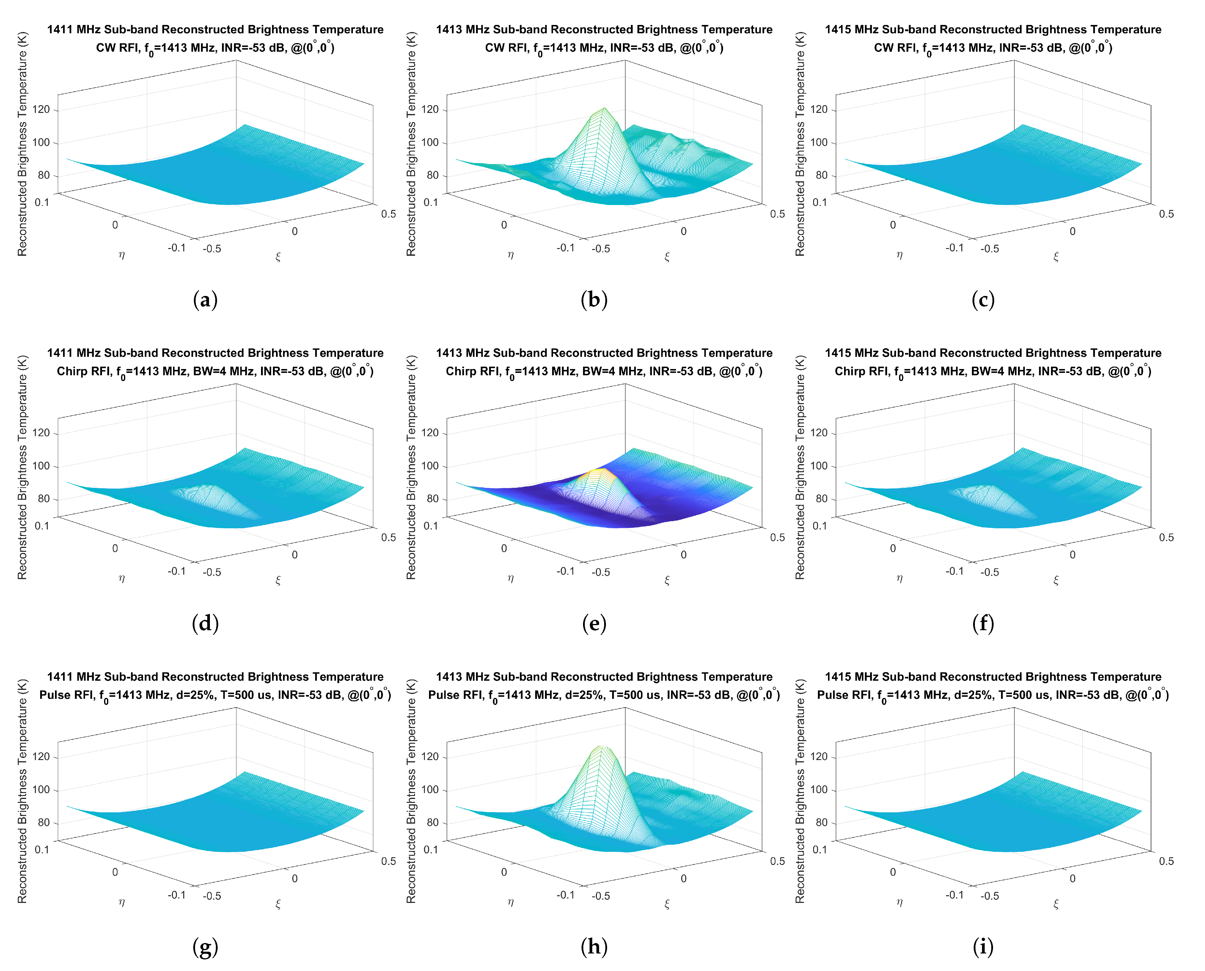
Figure 12 presents a sub-band reconstructed brightness temperature map when satellite flies through RFI source. Columns in the figure present the sub-band reconstructed brightness temperature map of 1411 MHz sub-band, 1413 MHz sub-band, and 1415 MHz sub-band, respectively. Rows in the figure present the RFI cases of CW, Chirp, Pulse, and SSC, respectively. The reconstructed brightness temperatures are obviously contaminated by RFI in both frequency domain and space domain.

4. Analysis on Simulation Results

The simulation system is able to assess how seriously RFI affects the observation of MICAP L-Rad and study RFI detection and mitigation method. Many RFI cases are simulated with the simulation system. RFI characteristics summarized in [41,42] provide a useful reference for the proper simulation of RFI cases. For instance, the pulse width of most pulse RFI is no more than 5 ms; the pulse repeat period of most pulse RFI is between 2 ms and 8 ms; the bandwidth of most narrow-band RFI is no more than 5 MHz. These parameters are used for RFI signal modeling. Studying how the parameters and positions of RFI affect the observation of MICAP L-Rad is the main objective of simulation. These behaviors are discussed based on the Monte-Carlo simulation results.

4.1. How RFI Affects Reconstructed Brightness Temperature

To assess how seriously RFI affects reconstructed brightness temperature, Root-mean-square error (RMSE) between clean full-band reconstructed brightness temperature and contaminated full-band reconstructed brightness temperature is used as an assessment indicator. Firstly, how the power of RFI affects reconstructed brightness temperature is assessed by setting up RFI sources at the center of AF-FOV and adjusting the power of these RFI sources. The relationship between full-band reconstructed brightness temperature RMSE and the power of RFI is shown in Figure 13a. Among all of the parameters of RFI, power has the most serious impact on full-band reconstructed brightness temperature. As RFI power decreases, the RMSE decreases linearly. Furthermore, the impacts of other parameters on the full-band reconstructed brightness temperature are much weaker than power.
As shown in Figure 12, when the satellite flies through the RFI located in the middle of the cross-track direction ( ξ -axis direction), only the reconstructed brightness temperature within ± 5 ( η [ 0.1 , 0.1 ] ) in the along-track direction ( η -axis direction) is affected by RFI. Beyond ± 5 ( η [ 0.1 , 0.1 ] ) in the along-track direction, the radiation from RFI will be tapered by the antenna pattern. Comparing the results shown in different columns, it can be found that the reconstructed brightness temperature of the sub-band without RFI will not be affected by RFI. If the contaminated sub-band reconstructed brightness temperature is removed, the reconstructed brightness temperature of other sub-band can still be used, which proves spectrum division is beneficial for RFI mitigations. Both Chirp RFI and SSC RFI are band-limited signals, and the symbol rate of SSC RFI is a parameter similar to the bandwidth of Chirp RFI. As bandwidth or symbol rate increases, the impact of these band-limited RFI on each sub-band reconstructed brightness temperature weakens. This is because both SSC RFI and Chirp RFI concentrate their spectral power into a limited spectrum.
Figure 13b shows the reconstructed brightness temperature RMSE when the RFI source is placed at different position in cross-track direction. As the power of RFI is the dominant factor, only Chirp RFI cases are considered in the figure. When RFI locates within AF-FOV, the radiation of RFI beyond ± 30 in the cross-track direction is attenuated by the antenna pattern. Combining Figure 13a,b, how different power of RFI located within AF-FOV affects reconstructed brightness temperature can be assessed. As shown in Figure 13c, when RFI locates beyond AF-FOV, the reconstructed brightness temperature within alise-free FOV is affected slightly. Because reconstructed brightness temperature is noise measurement, if reconstructed brightness temperature RMSE is lower than 3 unit of reconstructed brightness temperature measurement STD, the impact of RFI can be processed on the ground. According to (10), the transmitted power of the RFI source can be easily calculated by INR. The STD of full-band brightness temperature brightness of 1-s integration time is about 0.4 K. Therefore, If the INR of RFI located within AF-FOV is smaller than −52 dB, that is, the RFI transmitted power of RFI on the ground is smaller than −0.13 dBm, the RMSE is smaller than 1.2 K (3 times STD), and the impact of RFI source on the full-band brightness temperature brightness does not need to be processed in orbit. If the INR of RFI located beyond AF-FOV is bigger than −35 dB, that is, the RFI transmitted power of RFI on the ground is bigger than 16.87 dBm, the impact of RFI on full-band brightness temperature brightness does not need to be processed in orbit.

4.2. How RFI Affects Correlation

Cross-correlation is the principal correlation data product of MICAP L-Rad, as shown in Equation (2). In the ocean observation scene at L-band, The cross-correlation measured by long correlation baseline is inherently small. Thus, the impact of RFI on the cross-correlation of long correlation baseline is more serious. To study how RFI affects cross-correlation, the sub-band cross-correlation amplitude offset generated by RFI is normalized to the corresponding radiometric sensitivity. This sensitivity-normalized offset is used as a threshold that whether the RFI can be ignored by in-orbit RFI processing or not.
Figure 14 presents the normalized sub-band cross-correlation offset when satellite flies through a Chirp RFI, where the results are shown in different baselines and RFI locations. If RFI exists, there will always be a few correlation baselines contaminated by RFI. Comparing the results illustrated in Figure 12 and Figure 14, it can be easily found that the reconstructed brightness temperature offset caused by RFI is more obvious than the cross-correlation offset. It can be explained by the fact that the transformation from visibility function to brightness temperature concentrates the radiation power of RFI. Because the reconstructed brightness temperature is more sensitive to RFI than the visibility function, it is more efficient to detect RFI with the reconstructed brightness temperature. In addition, the impacts of power and bandwidth of RFI on sub-band cross-correlation are opposite. This is because the wider the bandwidth of RFI is, the smaller the power distributed into each sub-band is.

5. Conclusions

This paper presents an instrumental full-chain time-domain simulation system of MICAP L-Rad. By time-domain IF signal modeling, the simulation system can emulate how RFI impacts the complex correlation and the corresponding reconstructed brightness temperature. According to the simulation results, some constraints on RFI processing strategy are proposed. The power and location of RFI are found to be the dominant parameter that affects MICAP L-Rad measurement. If RFI locates within AF-FOV, the RFI with power more than −0.13 dBm needs to be detected in orbit. If RFI locates beyond AF-FOV, the RFI with power more than 16.87 dBm needs to be detected in orbit. In addition, the spectrum division realized by digital processing technique in MICAP L-Rad is effective on RFI detection. As reconstructed brightness temperature is found to be more sensitive to RFI than complex correlation, it is promising to use reconstructed brightness temperature as an RFI indicator. The corresponding three-dimensional RFI processing strategy will be carefully devised in a following study.

Author Contributions

T.G. and H.L. proposed the simulation system design; T.G. and C.Z. simulated the simulation system design; T.G. and X.G. analyzed the simulation results and edited the manuscript; C.Z. and J.W. supported funding; L.N. designed L-band receivers; D.H. edited the manuscript. All authors have read and agreed to the published version of the manuscript.

Funding

This work was supported by the National Natural Science Foundation of China under Grant 41675035.

Institutional Review Board Statement

Not applicable.

Informed Consent Statement

Not applicable.

Data Availability Statement

Not applicable.

Conflicts of Interest

The authors declare no conflict of interest.

References

  1. Schmitt, R.W. Salinity and the Global Water Cycle. Oceanography 2008, 21, 12–19. [Google Scholar] [CrossRef]
  2. Yin, X.; Boutin, J.; Martin, N.; Spurgeon, P.; Vergely, J.L.; Gaillard, F. Errors in SMOS Sea Surface Salinity and their dependency on a priori wind speed. Remote Sens. Environ. 2014, 146, 159–171. [Google Scholar] [CrossRef] [Green Version]
  3. Font, J.; Camps, A.; Borges, A.; Martín-Neira, M.; Boutin, J.; Reul, N.; Kerr, Y.H.; Hahne, A.; Mecklenburg, S. SMOS: The Challenging Sea Surface Salinity Measurement From Space. Proc. IEEE 2010, 98, 649–665. [Google Scholar] [CrossRef] [Green Version]
  4. Le Vine, D.; Pellerano, F.; Lagerloef, G.; Yueh, S.; Colomb, R. Aquarius: A Mission to Monitor Sea Surface Salinity from Space. In Proceedings of the 2006 IEEE MicroRad, San Juan, PR, USA, 28 February–3 March 2006; pp. 87–90. [Google Scholar] [CrossRef]
  5. Piepmeier, J.R.; Focardi, P.; Horgan, K.A.; Knuble, J.; Ehsan, N.; Lucey, J.; Brambora, C.; Brown, P.R.; Hoffman, P.J.; French, R.T.; et al. SMAP L-Band Microwave Radiometer: Instrument Design and First Year on Orbit. IEEE Trans. Geosci. Remote Sens. 2017, 55, 1954–1966. [Google Scholar] [CrossRef] [Green Version]
  6. Liu, H.; Zhu, D.; Niu, L.; Wu, L.; Wang, C.; Chen, X.; Zhao, X.; Zhang, C.; Zhang, X.; Yin, X.; et al. MICAP (Microwave imager combined active and passive): A new instrument for Chinese ocean salinity satellite. In Proceedings of the 2015 IEEE International Geoscience and Remote Sensing Symposium (IGARSS), Milan, Italy, 26–31 July 2015; pp. 184–187. [Google Scholar] [CrossRef]
  7. Zhang, L.; Yin, X.; Wang, Z.; Liu, H.; Lin, M. Preliminary Analysis of the Potential and Limitations of MICAP for the Retrieval of Sea Surface Salinity. IEEE J. Sel. Top. Appl. Earth Obs. Remote Sens. 2018, 11, 2979–2990. [Google Scholar] [CrossRef]
  8. Ellingson, S.W.; Johnson, J.T. A polarimetric survey of radio-frequency interference in C- and X-bands in the continental united states using WindSat radiometry. IEEE Trans. Geosci. Remote Sens. 2006, 44, 540–548. [Google Scholar] [CrossRef]
  9. Njoku, E.G.; Ashcroft, P.; Chan, T.K.; Li, L. Global survey and statistics of radio-frequency interference in AMSR-E land observations. IEEE Trans. Geosci. Remote Sens. 2005, 43, 938–947. [Google Scholar] [CrossRef]
  10. Li, L.; Gaiser, P.W.; Bettenhausen, M.H.; Johnston, W. WindSat radio-frequency interference signature and its identification over land and ocean. IEEE Trans. Geosci. Remote Sens. 2006, 44, 530–539. [Google Scholar] [CrossRef] [Green Version]
  11. Oliva, R.; Daganzo, E.; Soldo, Y.; Kerr, Y.; Cabot, F.; Richaume, P.; Anterrieu, E.; Gutierrez, A.; Barbosa, J.; Lopes, G. Status of RFI in the 1400–1427 MHz passive band: The SMOS perspective. In Proceedings of the 2014 XXXIth URSI General Assembly and Scientific Symposium (URSI GASS), Beijing, China, 16–23 August 2014; pp. 1–4. [Google Scholar] [CrossRef]
  12. Aksoy, M.; Johnson, J.T. A Study of SMOS RFI Over North America. IEEE Geosci. Remote Sens. Lett. 2013, 10, 515–519. [Google Scholar] [CrossRef]
  13. Bringer, A.; Daehn, M.; Johnson, J.T.; Soldo, Y.; Le Vine, D.M.; de Matthaeis, P.; Piepmeier, J.R.; Mohammed, P. SMAP Mission: Changes in the RFI Environment. In Proceedings of the IGARSS 2018-2018 IEEE International Geoscience and Remote Sensing Symposium, Valencia, Spain, 22–27 July 2018; pp. 3754–3757. [Google Scholar] [CrossRef]
  14. Mohammed, P.N.; Aksoy, M.; Piepmeier, J.R.; Johnson, J.T.; Bringer, A. SMAP L-Band Microwave Radiometer: RFI Mitigation Prelaunch Analysis and First Year On-Orbit Observations. IEEE Trans. Geosci. Remote Sens. 2016, 54, 6035–6047. [Google Scholar] [CrossRef]
  15. Lan, H.; Zhao, T.; Zhang, Z.; Shi, J. A preliminary survey of L-band radio frequency interference over China by using aquarius observations. In Proceedings of the 2014 IEEE Geoscience and Remote Sensing Symposium, Quebec City, QC, Canada, 13–18 July 2014; pp. 1757–1760. [Google Scholar] [CrossRef]
  16. Park, H.; González-Gambau, V.; Camps, A. High Angular Resolution RFI Localization in Synthetic Aperture Interferometric Radiometers Using Direction-of-Arrival Estimation. IEEE Geosci. Remote Sens. Lett. 2015, 12, 102–106. [Google Scholar] [CrossRef] [Green Version]
  17. Park, H.; González-Gambau, V.; Camps, A.; Vall-llossera, M. Improved MUSIC-Based SMOS RFI Source Detection and Geolocation Algorithm. IEEE Trans. Geosci. Remote Sens. 2016, 54, 1311–1322. [Google Scholar] [CrossRef] [Green Version]
  18. Park, H.; Camps, A.; Vall-Llossera, M.; Gonzalez-Gambau, V. Strong RFI Impact Mitigation in the Synthetic Aperture Interferometric Radiometer. In Proceedings of the 2018 IEEE 15th Specialist Meeting on Microwave Radiometry and Remote Sensing of the Environment (MicroRad), Cambridge, MA, USA, 27–30 March 2018; pp. 1–4. [Google Scholar] [CrossRef] [Green Version]
  19. Soldo, Y.; Khazaal, A.; Cabot, F.; Anterrieu, E.; Richaume, P. RFI mitigation for SMOS: A distributed approach. In Proceedings of the 2012 IEEE International Geoscience and Remote Sensing Symposium, Munich, Germany, 22–27 July 2012; pp. 3327–3330. [Google Scholar] [CrossRef]
  20. Le Vine, D.M.; de Matthaeis, P.; Ruf, C.S.; Chen, D.D. Aquarius RFI Detection and Mitigation Algorithm: Assessment and Examples. IEEE Trans. Geosci. Remote Sens. 2014, 52, 4574–4584. [Google Scholar] [CrossRef]
  21. Ruf, C.; Misra, S. Detection of Radio Frequency Interference with the Aquarius Radiometer. In Proceedings of the 2007 IEEE International Geoscience and Remote Sensing Symposium, Barcelona, Spain, 23–28 July 2007; pp. 2722–2725. [Google Scholar] [CrossRef]
  22. Piepmeier, J.R.; Johnson, J.T.; Mohammed, P.N.; Bradley, D.; Ruf, C.; Aksoy, M.; Garcia, R.; Hudson, D.; Miles, L.; Wong, M. Radio-Frequency Interference Mitigation for the Soil Moisture Active Passive Microwave Radiometer. IEEE Trans. Geosci. Remote Sens. 2014, 52, 761–775. [Google Scholar] [CrossRef]
  23. Ruf, C.; Gross, S.; Misra, S. RFI detection and mitigation for microwave radiometry with an agile digital detector. IEEE Trans. Geosci. Remote Sens. 2006, 44, 694–706. [Google Scholar] [CrossRef]
  24. Johnson, J.T.; Ball, C.; Chen, C.C.; McKelvey, C.; Smith, G.E.; Andrews, M.; O’Brien, A.; Garry, J.L.; Misra, S.; Bendig, R.; et al. Real-Time Detection and Filtering of Radio Frequency Interference Onboard a Spaceborne Microwave Radiometer: The CubeRRT Mission. IEEE J. Sel. Top. Appl. Earth Obs. Remote Sens. 2020, 13, 1610–1624. [Google Scholar] [CrossRef] [Green Version]
  25. Misra, S.; Kocz, J.; Jarnot, R.; Brown, S.T.; Bendig, R.; Felten, C.; Johnson, J.T. Development of an On-Board Wide-Band Processor for Radio Frequency Interference Detection and Filtering. IEEE Trans. Geosci. Remote Sens. 2019, 57, 3191–3203. [Google Scholar] [CrossRef]
  26. Querol, J.; Perez, A.; Camps, A. A Review of RFI Mitigation Techniques in Microwave Radiometry. Remote Sens. 2019, 11, 3042. [Google Scholar] [CrossRef] [Green Version]
  27. Díez-García, R.; Camps, A. A Novel RFI Detection Method for Microwave Radiometers Using Multilag Correlators. IEEE Trans. Geosci. Remote Sens. 2021, 1–12, Early Access. [Google Scholar] [CrossRef]
  28. Li, Y.; Liu, H.; Zhang, A. End-to-End Simulation of WCOM IMI Sea Surface Salinity Retrieval. Remote Sens. 2019, 11, 217. [Google Scholar] [CrossRef] [Green Version]
  29. Camps, A.; Park, H.; Kang, Y.; Bandeiras, J.; Barbosa, J.; Vieira, P.; Friaças, A.; D’Addio, S. Microwave Imaging Radiometers by Aperture Synthesis Performance Simulator (Part 2): Instrument Modeling, Calibration, and Image Reconstruction Algorithms. J. Imaging 2016, 2, 18. [Google Scholar] [CrossRef] [Green Version]
  30. Corbella, I.; Duffo, N.; Vall-llossera, M.; Camps, A.; Torres, F. The visibility function in interferometric aperture synthesis radiometry. IEEE Trans. Geosci. Remote Sens. 2004, 42, 1677–1682. [Google Scholar] [CrossRef]
  31. Niu, L.; Liu, H.; Wu, J. Analysis and experimental study of high stability microwave radiometer. In Proceedings of the 2014 IEEE Geoscience and Remote Sensing Symposium, Quebec City, QC, Canada, 13–18 July 2014; pp. 1910–1913. [Google Scholar] [CrossRef]
  32. Lyons, R.G. Understanding Digital Signal Processing, 3rd ed.; Prentice Hall: New York, NY, USA, 2011; pp. 342–343. [Google Scholar]
  33. Zahirniak, D.R.; Sharpin, D.L.; Fields, T.W. A hardware-efficient, multirate, digital channelized receiver architecture. IEEE Trans. Aerosp. Electron. Syst. 1998, 34, 137–152. [Google Scholar] [CrossRef]
  34. Piepmeier, J.R.; Gasiewski, A.J. Digital correlation microwave polarimetry: Analysis and demonstration. IEEE Trans. Geosci. Remote Sens. 2001, 39, 2392–2410. [Google Scholar] [CrossRef]
  35. Hagen, J.B.; Farley, D.T. Digital-correlation techniques in radio science. Radio Sci. 1973, 8, 775–784. [Google Scholar] [CrossRef]
  36. Ruf, C.S.; Swift, C.T.; Tanner, A.B.; Le Vine, D.M. Interferometric synthetic aperture microwave radiometry for the remote sensing of the Earth. IEEE Trans. Geosci. Remote Sens. 1988, 26, 597–611. [Google Scholar] [CrossRef]
  37. Corbella, I.; Torres, F.; Camps, A.; Duffo, N.; Vall-llossera, M. Brightness-Temperature Retrieval Methods in Synthetic Aperture Radiometers. IEEE Trans. Geosci. Remote Sens. 2009, 47, 285–294. [Google Scholar] [CrossRef]
  38. Ruf, C.; Li, J. A correlated noise calibration standard for interferometric, polarimetric, and autocorrelation microwave radiometers. IEEE Trans. Geosci. Remote Sens. 2003, 41, 2187–2196. [Google Scholar] [CrossRef]
  39. Mahafza, B.R. MATLAB Simulations for Radar Systems Design, 1st ed.; CRC Press: London, UK, 2000; pp. 8–9. [Google Scholar]
  40. Zhang, A.; Liu, H.; Wu, L.; Niu, L.; Zhang, C.; Chen, X.; Wu, J. The Application of the G-matrix Modification Method to the Imaging of the 1-D Synthetic Aperture Microwave Radiometer. J. Electron. Inf. Technol. 2019, 41, 2632–2638. [Google Scholar] [CrossRef]
  41. Soldo, Y.; Oliva, R.; Vine, D.L.; Bringer, A.; de Matthaels, P. Retrieval of RFI Characteristics Using L-Band Satellite Data. In Proceedings of the IGARSS 2020-2020 IEEE International Geoscience and Remote Sensing Symposium, Waikoloa, HI, USA, 26 September–2 October 2020; pp. 3766–3769. [Google Scholar] [CrossRef]
  42. Aksoy, M.; Rajabi, H.; Atrey, P.; Mohamed Nazar, I. Characteristics of the Global Radio Frequency Interference in the Protected Portion of L-Band. Remote Sens. 2021, 13, 253. [Google Scholar] [CrossRef]
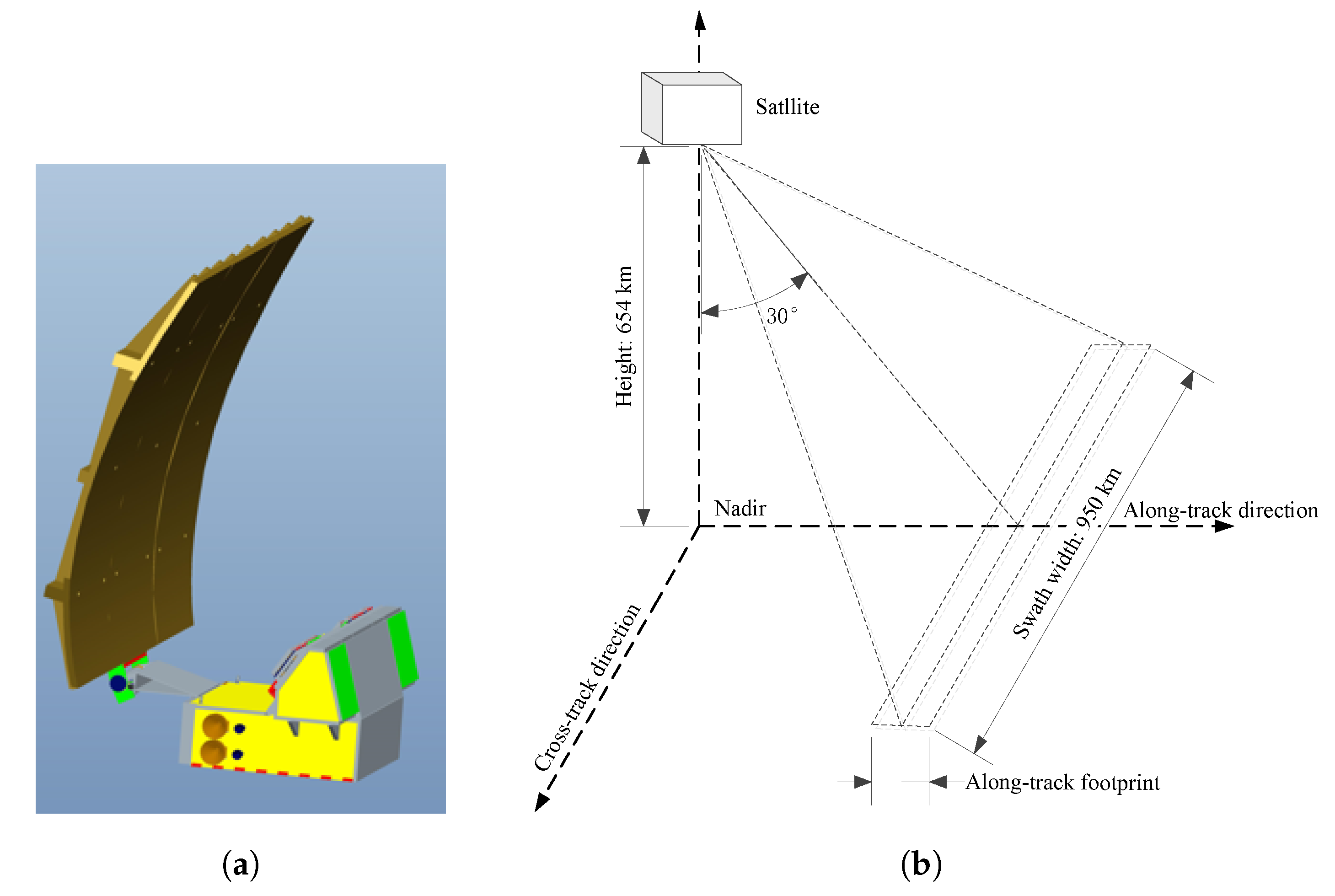
Figure 1. (a) The structure diagram of MICAP. (b) The observation schematic diagram of MICAP.
Remotesensing 13 03230 g001
Figure 2. MICAP L-Rad system block diagram.
Remotesensing 13 03230 g002
Figure 3. MICAP L-Rad antenna feed layout.
Remotesensing 13 03230 g003
Figure 4. The block diagram of L-band receiver.
Remotesensing 13 03230 g004
Figure 5. Digital subsystem block diagram.
Remotesensing 13 03230 g005
Figure 6. Amplitude spectrums of channelizer equivalent filter banks.
Remotesensing 13 03230 g006
Figure 7. Spectrograms of RFI IF signals. (a) CW RFI ( F c = 31.25 MHz, P R F I I F = 1 W); (b) Pulse RFI ( F c = 31.25 MHz, T p u l s e = 2 ms, d = 20 % , P R F I I F = 1 W); (c) Chirp RFI ( F c = 31.25 MHz, T c h i r p = 2 ms, B c h i r p = 4 MHz, P R F I I F = 1 W); (d) SSC RFI ( F c = 31.25 MHz, S = 4 MSaps, P R F I I F = 1 W).
Remotesensing 13 03230 g007
Figure 8. Brightness temperature distribution of ocean. The dark blue region is the cosmic background, and the light blue region is the earth disk.
Remotesensing 13 03230 g008
Figure 9. Simulation system block diagram: (a) observation mode; (b) calibration mode.
Remotesensing 13 03230 g009
Figure 10. Functional verification of the simulation system. (a) Simulated sub-band visibility function and simulation error when RFI does not exist. (b) The simulated sub-band visibility function sensitivity of 10-ms integration time.
Remotesensing 13 03230 g010
Figure 11. Simulation results of brightness temperature reconstruction without RFI in 1-s integration time, (a) single sub band, and (b) full band.
Remotesensing 13 03230 g011
Figure 12. The sub-band reconstructed brightness temperature map when satellite flies through RFI source. ξ -axis is the cross-track direction. η -axis is the along-track direction. Columns in the figure present the sub-band reconstructed brightness temperature map of 1411 MHz sub-band, 1413 MHz sub-band, and 1415 MHz sub-band, respectively. Rows in the figure present the RFI cases of CW, Chirp, Pulse, and SSC, respectively.
Remotesensing 13 03230 g012aRemotesensing 13 03230 g012b
Figure 13. (a) Maximum reconstructed brightness temperature offset vs. RFI power. (b) Reconstructed brightness temperature RMSE vs. RFI position in the cross-track direction. (c) Reconstructed brightness temperature RMSE vs. RFI power beyond AF-FOV.
Remotesensing 13 03230 g013
Figure 14. Normalized sub-band cross-correlation offset. The INR of RFI in 1–2 row is −53 dB and −50 dB, respectively. The positions of RFI in 1–3 column are ( 0 , 0 ) , ( 10 , 0 ) , and ( 20 , 0 ) , respectively.
Remotesensing 13 03230 g014
Table 1. Main Specifications of L/C/K-Rad.
InstrumentL-RadC-RadK-Rad
Frequency1.4135 GHz6.9 GHz18.7 GHz
Bandwidth25 MHz200 MHz200 MHz
PolarizationH,V,T3H,VH,V
Incident angle30~50 30~50 30~50
Radiometric resolution
@ sampling interval
(boresight)
0.15 K @ 75 km0.5 K @15 km0.5 K @15 km
Spatial resolution
(along-track)
75 km15 km15 km
Spatial resolution
(cross-track)
50~100 km25~50 km25~50 km
Publisher’s Note: MDPI stays neutral with regard to jurisdictional claims in published maps and institutional affiliations.