Abstract
The precise orbit determination (POD) accuracy of the Chinese BeiDou Navigation Satellite System (BDS) is still not comparable to that of the Global Positioning System because of the unfavorable geometry of the BDS and the uneven distribution of BDS ground monitoring stations. Fortunately, low Earth orbit (LEO) satellites, serving as fast moving stations, can efficiently improve BDS geometry. Nearly all studies on Global Navigation Satellite System POD enhancement using large LEO constellations are based on simulations and their results are usually overly optimistic. The receivers mounted on a spacecraft or an LEO satellite are usually different from geodetic receivers and the observation conditions in space are more challenging than those on the ground. The noise level of spaceborne observations needs to be carefully calibrated. Moreover, spaceborne observational errors caused by space weather events, i.e., solar geomagnetic storms, are usually ignored. Accordingly, in this study, the actual spaceborne observation noises are first analyzed and then used in subsequent observation simulations. Then, the observation residuals from the actual-processed LEO POD during a solar storm on 8 September 2017 are extracted and added to the simulated spaceborne observations. The effect of the observational errors on the BDS POD augmented with different LEO constellation configurations is analyzed. The results indicate that the noise levels from the Swarm-A, GRACE-A, and Sentinel-3A satellites are different and that the carrier-phase measurement noise ranges from 2 mm to 6 mm. Such different noise levels for LEO spaceborne observations cause considerable differences in the BDS POD solutions. Experiments calculating the augmented BDS POD for different LEO constellations considering spaceborne observational errors extracted from the solar storm indicate that these errors have a significant influence on the accuracy of the BDS POD. The 3D root mean squares of the BDS GEO, IGSO, and MEO satellite orbits are 1.30 m, 1.16 m, and 1.02 m, respectively, with a Walker 2/1/0 LEO constellation, and increase to 1.57 m, 1.72 m, and 1.32 m, respectively, with a Walker 12/3/1 constellation. When the number of LEO satellites increases to 60, the precision of the BDS POD improves significantly to 0.89 m, 0.77 m, and 0.69 m for the GEO, IGSO, and MEO satellites, respectively. While 12 satellites are sufficient to enhance the BDS POD to the sub-decimeter level, up to 60 satellites can effectively reduce the influence of large spaceborne observational errors, i.e., from solar storms.
1. Introduction
Currently, the precise orbit determination (POD) accuracy of the Chinese BeiDou Navigation Satellite System (BDS) is not comparable to that of the Global Positioning System (GPS) or Global Navigation Satellite System (GLONASS), which is a disadvantage of the BDS in providing high precision service to global users. In addition to the inaccurate solar radiation pressure model and the special attitude control mode of the BDS [1,2,3], one other reason for this lies in the few and unevenly distributed global BDS monitoring stations. Furthermore, the generally static characteristics of the BDS’ geostationary orbit (GEO) satellite to the ground stations leads to a poor orbit determination accuracy, even if the ground tracking stations were to be globally distributed. Currently, the 3D orbital accuracy of BDS GEO satellites is at the meter level using the current BDS ground monitoring stations [4,5]. Fortunately, weaknesses in the observability and tracking geometry can be overcome by introducing low Earth orbit (LEO) satellites as moving stations. LEO satellites have been primarily used for Earth observations, commercial communications, and navigation over the past 20 years, and the Iridium constellation is the world’s first LEO satellite constellation used primarily for mobile communication, integrating the functions of communication and navigation [6]. This constellation can provide navigation services or augment GNSS for positioning.
Simulations of BDS POD enhancement with large LEO constellations have been conducted by many researchers [7,8,9,10]. It has been found that, compared with a ground-based POD, a remarkable accuracy improvement of over 70% can be observed for all GNSS satellites when a large LEO constellation with 60 satellites is introduced, with the orbital accuracy of BDS GEO satellites reaching the centimeter level. In particular, Li et al. [8] simulated 66 satellites of the Iridium satellite constellation and found that the “one-step” method, in which the GNSS and LEO orbits and the satellite clock offsets are estimated simultaneously, generates the best orbit and clock accuracy. However, the problem of time consumption needs to be taken into consideration because dozens of hours of computation are not beneficial for real-time services; accordingly, it has been concluded that introducing part of an LEO constellation could be an effective way to balance the conflict between the orbital accuracy and the computational efficiency. Li et al. [10] studied the effect of satellite numbers, orbital types, and altitudes, as well as global and regional ground networks on the LEO-constellation-augmented GNSS POD performance. Their results indicate that a sun-synchronous-orbiting LEO constellation could yield a better tracking geometry for GNSS satellites and a stronger augmentation than a polar-orbiting constellation. Furthermore, the GNSS orbit accuracy is less dependent on ground stations when incorporating a large number of LEO satellites.
One common problem in the above studies is that the simulations are overly ideal. In typical cases, spaceborne observational errors are generally ignored. In various simulations, the measurement noise of onboard receivers had been treated as being the same as that of ground geodetic receivers, i.e., the pseudo-range noise is set to 1 m and the carrier-phase measurement noise is set to 0.005 m [8]. For a large LEO constellation, the performances of the GNSS receivers onboard the LEO satellites are usually different from those of the geodetic receivers [6,11] and, therefore, the noise level needs to be analyzed with actual observations and then carefully calibrated for the simulation. Otherwise, the simulated LEO-constellation-augmented GNSS POD will not accurately reflect the actual situation.
In addition, the outer space environment is much more complicated than the ground environment and solar particles emitted from a solar storm may damage the hardware of a spacecraft or a satellite. This could lead to the abnormal operation of instruments mounted on the satellite, especially the GNSS receiver, seriously affecting the observation quality [12,13,14].
The POD of spacecrafts and satellites can be seriously affected by charged particles ejected by the sun. This is especially true for LEO satellites because most of them hold a near-polar orbit and the orbit estimation accuracy can be degraded by the interference of the Earth’s magnetic field and solar wind particles. In addition, solar storms affect the Earth’s upper atmosphere, destroying the structure of the ionosphere. The operation of onboard GNSS receivers can be easily degraded or interrupted by ionospheric scintillations at altitudes of LEO satellites (200–1000 km). During a solar storm, the behavior of the ionosphere differs significantly from its behavior during quiet times and the risk of degradation of the GNSS signal amplitude or a failure to acquire signals in severe cases increases considerably, as has been reported in many studies [15,16,17]. Degraded GNSS signals can reduce the availability and reliability of the GNSS-based POD. In addition, with increasing ionospheric density, the accuracy of a conventional orbit determination is seriously reduced [18].
The effect of spaceborne observational errors on a large LEO-constellation-augmented GNSS POD has not yet been studied. We focus on the effects of actual observational errors on the BDS/LEO combined POD in this study. First, in Section 2, BDS-3, as well as various other LEO constellations, is designed and the approach for ground-based and spaceborne observation simulations based on the BDS-3/LEO orbits is introduced. Then, the LEO-constellation-augmented BDS POD strategies are described in detail in Section 3. In the experiments described and analyzed in Section 4, the actual spaceborne measurement noise is first evaluated and then taken as the calibration value for the subsequent observation simulations. Then, the observational errors extracted from real-observed spaceborne data are analyzed and added to the simulated observations. The effects of these observational errors on the BDS PODs augmented with various LEO constellations are then assessed. The shortcomings of the work and an outlook for future research are summarized in Section 5. Some useful conclusions are given to provide references for future LEO constellation designs in Section 6.
2. Constellation Design and Data Simulation
In order to evaluate the performance of an LEO-constellation-augmented BDS POD with consideration of the measurement errors of onboard BDS observations, five different types of LEO constellations including Walker 2/1/1, Walker 6/2/1, Walker 12/3/2, Walker 24/4/2, and Walker 60/6/4 are designed. The BDS and LEO orbits are generated and the observations of ground stations and spaceborne BDS data are simulated to evaluate the BDS/LEO POD under different observation conditions.
2.1. BDS/LEO Combined Constellation Configurations
According to the nominal parameter configuration of the BDS constellation, the full constellation BDS-3 comprises three GEO, three inclined geosynchronous orbits (IGSO), and 24 medium Earth orbit (MEO) satellites, with the orbital inclinations of the GEO and IGSO satellites being 0° and 55°, respectively, and all the orbital altitudes being 35,786 km. The three GEO satellites are placed at eastern longitudes of 80°, 110.5°, and 140°, and the three IGSO satellites are at ascending-node geographical longitudes of 0°, 120°, and 240°. The 24 MEO satellites are in a sun-synchronous-orbiting constellation called the Walker 24/3/1 constellation [19], in which the 24 satellites are placed on three planes.
To assess the impact of the size of the LEO constellation on the BDS POD, five polar circular orbits with different numbers of LEO satellites were designed, namely, the Walker 2/1/0, Walker 6/2/1, Walker 12/3/1, Walker 24/4/2, and Walker 60/6/4 constellations, which are shown in Figure 1b–f, respectively. According to previous studies, up to 60 LEO satellites are sufficient to enhance the BDS orbits to achieve the best accuracy [9,10]. This set of gradually increasing satellite numbers is used to determine the minimum number of LEO satellites that can fully enhance the BDS POD to achieve the best performance. For each constellation, satellites are placed on a certain number of equally spaced planes with the orbital altitudes of 1200 km and the inclinations of 86.4° to the equatorial plane for all satellites. The nominal parameter configurations are shown in Table 1. The dynamic models for the constellation configurations are listed in Table 2.
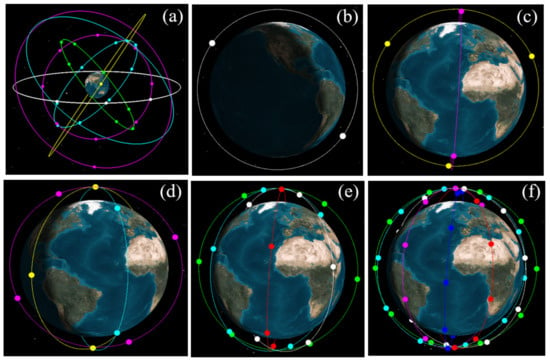
Figure 1.
Designed BDS-3/LEO constellation: (a) BDS-3, (b) Walker 2/1/0, (c) Walker 6/2/1, (d) Walker 12/3/1, (e) Walker 24/4/2, and (f) Walker 60/6/4.

Table 1.
Nominal parameters of the BDS-3/LEO constellation configurations.
Table 2.
The dynamic models applied in the constellation configurations.
2.2. Simulation of Observations
Two types of observations, namely ground-tracking and spaceborne BDS data, were simulated. Considering the BDS monitoring stations are primarily located in China, six ground stations located in China, namely GUA1, CHU1, XIA1, SHA1, LHA1, and KUN1, chosen from the International GNSS Monitoring and Assessment System (iGMAS) network were used for the observation simulation. The time span was from day 001 to day 003 in 2019 and the sampling interval was 10 s. The station distribution is shown in Figure 2.
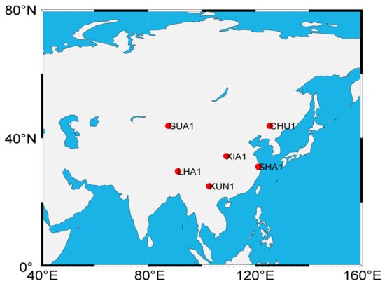
Figure 2.
The distribution of ground tracking stations.
Different from the ground receivers, the receivers in space are cycling at a speed of several kilometers per second. Therefore, we need to clarify some special characteristics of the GNSS receivers mounted on the LEO satellites to ensure that GNSS signals can be tracked reliably and continuously. First, the strength of the satellite signal received by the spaceborne receiver changes rapidly. Sometimes, the signal is very weak, only a few dB. It is required that the spaceborne receiver should have a very sensitive signal-receiving system to receive very weak satellite signals. Then, the onboard receiver should have the ability of resisting harsh environmental interference, i.e., the strong solar ultraviolet radiation and charged particles ejected by a solar storm. Finally, the receivers should be equipped with multiple pairs of GPS signal antennas pointing to different directions to satisfy various applications.
Simulations of ground or spaceborne observations is in fact the reverse process of positioning. B1c (1575.42 MHz) and B2a (1176.45 MHz) were set for the carrier-phase frequency for all BDS-3 satellites. For the sake of simplicity and convenience, the GPS L1 (1575.42 MHz) and L2 (1227.60 MHz) carrier frequencies were adopted for all LEO satellites. The accurate coordinates were fixed to the International GNSS Service (IGS) weekly solution. The algorithms of the observation simulation have already been described in peer-reviewed publications, i.e., in Ge et al. [8] and Li et al. [10]. Most of the observational errors need to be carefully considered so as to make the simulated data as close to the actual-observed data as possible. The satellite–receiver geometric distance was computed using the center-of-mass positions of the satellite and the receiver, which was corrected using the phase center offsets (PCO) and variations (PCV) of the satellite antennas. For the geometry observation model of the ground observations, the relativistic effect, phase wind-up corrections, tidal displacements, dry tropospheric delay, and hardware delays were all considered [25,26]. The igs14 antenna information (https://files.igs.org/pub/station/general/igs14_2148.atx accessed on 20 June 2021) was applied for the BDS-3 satellites; meanwhile, this information was set to zero for the LEO satellites.
Regarding the simulation of the ground observations, the receiver-independent error sources including the receiver clock offsets, the zenith wet delay, and the inter-system bias (ISB) between the LEO and BDS satellites were obtained by processing actual static multi-GNSS data. The ISB parameter is usually referred to as the difference in the code hardware delay between two GNSS; here, the standard deviation of the hardware delay was set to 0.1 m [27]. The dry component of the slant tropospheric delay was computed using the Saastamoinen model [28] together with the global mapping function (GMF) [29]. Meanwhile, the ionospheric delay errors were not considered because ionosphere-free (IF) combined observations were used for the POD. The other errors, including the multipath and atmospheric residual errors, were taken from the actual residuals of multi-GNSS PPP performed on the above iGMAS stations and were added to the simulated code and carrier-phase measurements.
The geometric models for the spaceborne observation simulations were nearly the same as those for the ground observations except that the tropospheric delay was not considered, nor was the first-order ionospheric delay because IF combination observations were applied [30]. However, the high-order ionospheric delays need to be treated carefully when encountering serious space weather such as geomagnetic storms. The PCO value was set to 0 for the LEO spaceborne observations and the PCVs were ignored. The pseudo-range and carrier-phase measurement noises were set to a zero-mean normal distribution with the standard deviation (STD) calculated from actual-observed onboard GPS data. The observation weighting was set dependent on the satellite elevation, , where the weighting was 1 if and otherwise. Similar to the ground observations, the other errors, i.e., the spaceborne atmospheric residual errors, were taken from actual-calculated spaceborne observation residuals and applied to the simulated observations. The onboard receiver clock offsets were taken from actual-processed receiver clock offsets onboard an LEO satellite in orbit.
The ambiguities were simulated as an integer number of constant cycles for each continuous observation arc. The code and phase delays were set to float constants near zero. Some random cycles of cycle slips were introduced on certain epochs throughout the entire time series. As for the satellite clock offsets, GNSS satellites are equipped with highly stable atomic cesium or rubidium clocks (with long-term stability on the order of 10−13 s) and the GeoForschungsZentrum (GFZ) 5-min interval multi-GNSS final clock offset products were used to simulate the BDS-3 satellite clock errors. The Earth orientation parameters (EOP) were taken from the IGS values.
3. LEO-Constellation-Augmented BDS POD Strategies
For the algorithms of the GNSS/LEO combined POD, readers can refer to Li et al. [7,10]; the processing strategies and parameters to be estimated are listed in Table 3. Considering a regional network was used, the processing arc was three days. The dynamic models applied for POD are almost the same as those used for the constellation configuration and are listed in Table 2. Note that there are two differences between the force models for the BDS and LEO POD. The atmospheric drag model was not considered for the BDS because of the thin atmosphere at its orbital altitude. Unlike GNSS satellites, the trajectories of LEO satellites undergo perturbations from both the solar radiation pressure and the atmospheric drag; therefore, the atmospheric drag plays a dominant role in the non-gravitational forces. The air density model DTM94 was applied for the LEO satellites and the parameters were estimated every 6 h. Empirical accelerations were only considered for the LEO satellites; one set of piecewise periodic parameters per revolution were added to the along, cross, and radial components and were estimated every 2 h.
Table 3.
The processing strategies for the BDS/LEO combined POD.
The detailed POD procedure is as follows.
- (1)
- First, the designed BDS and LEO ephemerides are converted to a broadcast ephemeris and used as the initial values for the POD. An 18-parameter model [31] is used for the BDS broadcast ephemeris design.
- (2)
- The initial BDS positions are obtained from the generated broadcast ephemeris and then the BDS initial dynamics information is derived via orbit dynamics fitting. The positions of the LEO satellites are derived from the kinematic POD using the BDS broadcast ephemeris and LEO spaceborne data, and then the LEO orbit initial dynamics information is obtained via orbit dynamics fitting.
- (3)
- Orbit integration is applied for the BDS and LEO satellite dynamics to obtain the initial reference orbit and state transition matrix.
- (4)
- The unknown parameters are ranked, combined, and added with the constraints listed in Table 3, and the POD equations are linearized at the reference initial orbit. The observations at all epochs are stacked on a combined adjustment for parameter estimation.
- (5)
- The adjusted BDS and LEO reference orbits are obtained via orbit integration after having resolved the normal equations.
- (6)
- Considering several random cycles of cycle slips are added to the observations, posterior residual editing is conducted until new cycle slips are detected and calibrated.
- (7)
- Steps 3–5 are repeated until the residuals are smaller than the given threshold values. In terms of the carrier-phase measurements, the threshold is usually defined as three times the post-fit STD value. The carrier-phase measurement can be regarded as “bad” and abandoned if the corresponding residual is larger than the threshold value. An ambiguity parameter is introduced and involved in calculation when the residual is larger than one and a half times the STD value. Otherwise, the residuals are regarded as white noises with normal distribution. This step is necessary because the actual-measured code and carrier-phase residuals are included in the observation simulation.
- (8)
- Finally, the BDS and LEO satellite orbit dynamics and clock products are calculated and the precise orbits can be derived via orbit integration with the orbit dynamics information. The estimated final orbits are compared with the “true” orbits, which are described in Section 2.1. A flowchart of the above procedures is given in Figure 3.
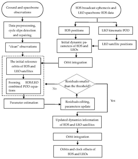 Figure 3. Flowchart for the BDS/LEO combined POD.
4. Experimental Analysis
We first evaluated the pseudo-range and carrier-phase measurement noise of the Swarm, GRACE, and Sentinel spaceborne GPS data. Then, the spaceborne observation data are simulated for the designed five LEO constellations, applying the real-calculated measurement noise. The BDS/LEO POD is finally evaluated with and without considering the spaceborne observation errors.
4.1. Analysis of the Spaceborne Measurement Noise
The a priori measurement noise of the ground observations is usually set as the default for positioning or orbit determinations, i.e., the pseudo-range and carrier-phase noises are usually set to 1 m and 5 mm, respectively, regardless the type of receiver [7,8]. However, receivers mounted on a spaceborne instrument, such as an LEO satellite, do not always have the same performance as geodetic receivers. The measurement noise reflects the inner properties of a receiver and is usually regarded as a factory calibration value; in addition, it does not change unless the hardware of the spaceborne receiver is damaged in an extreme space event, such as a strong solar storm. To identify the actual measurement noise for our observation simulation, the different magnitudes of the measurement noise levels of the simulated BDS/LEO combined POD are first calculated and compared; then, the measurement noises of the three types of real LEO constellations are analyzed.
The Walker 24/4/2 LEO constellation was used to calculate the effects of different levels of measurement noise on the BDS POD. According to our knowledge of the observation quality of the GNSS receivers, carrier-phase measurement noises of 0.001 m, 0.005 m, 0.01 m, and 0.05 m were calculated. The results are shown in Figure 4.
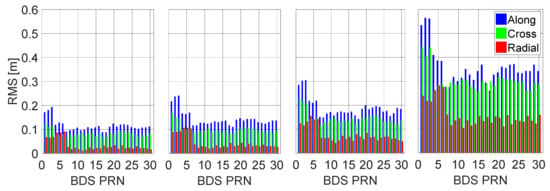
Figure 4.
BDS orbit solutions calculated with different levels of spaceborne measurement noise. From left to right: 0.001 m, 0.005 m, 0.01 m, and 0.05 m.
We can see there is an evident difference in the BDS orbit accuracies calculated from different levels of measurement noise: the average GEO, IGSO, and MEO 3D RMS values are 0.24 m, 0.17 m, and 0.14 m, respectively, for the 0.001-m noise level. When the noise level increases to 0.005 m and 0.01 m, the orbit accuracy decreases by 14.3%, 26.1%, and 30.0%, and by 36.8%, 41.4%, and 39.1% on average for the GEO, IGSO, and MEO satellites, respectively. For a noise level of 0.05 m, the orbit accuracy degrades considerably to approximately 0.73 m, 0.54 m, and 0.47 m on average. Therefore, it is necessary to identify and calibrate the actual spaceborne measurement noise.
Table 4 lists detailed information concerning the Swarm, GRACE, and Sentinel-3 constellations. The Swarm constellation consists of three identical satellites: Swarm-A, Swarm-B, and Swarm-C. Swarm-A and Swarm-C are flying in a synchronous formation at an altitude of approximately 460 km and an inclusion of 87.35°, while Swarm-B is cruising at a higher altitude of approximately 510 km. The Swarm constellation is dedicated to exploring the Earth’s magnetic field, atmosphere, and gravitational field. The satellites are equipped with several instruments including an absolute scalar magnetometer, an electric field instrument, and a GPS receiver (GPSR) [32]. The dual-frequency 1-s sampling interval spaceborne GPS data are used in this study; these data are freely available at ftp://swarm-diss.eo.esa.int/Level1b/ accessed on 5 June 2021.
Table 4.
Detailed information of Swarm, GRACE, and Sentinel-3 constellations.
The GRACE constellation consists of two identical satellites that are 220 km apart in orbit at an altitude of 300–500 km. The precise scientific instruments mounted on the satellite can accurately measure the distance between the two satellites, allowing variations in the gravity field to be detected. The spaceborne GPS receiver can track the GPS signal for the POD of the satellites; the spaceborne GPS data and corresponding data conversion tool can be downloaded from https://isdc.gfz-potsdam.de/grace-isdc/, accessed on 5 June 2021.
Sentinel-3 is a multi-sensor system used to measure the sea-surface topography, land and sea-surface temperature, and color of the land and sea with high precision and reliability to support marine prediction systems and environmental and climate monitoring. Images were obtained with various ocean and land color sensing instruments, sea and land surface temperature radiometers, and synthetic aperture radar altimeter, microwave radiometer, and POD instruments. Its ocean and land revisit cycles are less than 3.8 days and 1.4 days, respectively. Unlike Swarm and GRACE, the orbit determination for an individual Sentinel-3 satellite can be performed via GPS, Doppler orbit determination and radio-positioning integrated by satellite, or satellite laser ranging. In this study, only GPS data were used; the observations were obtained from https://scihub.copernicus.eu/gnss, accessed on 5 June 2021.
In this study, we calculated the measurement noise for the Swarm-A, GRACE-A pseudo-range, and carrier-phase spaceborne GPS observations with a cut-off elevation of 1°, and 10° for the Sentinel-3A observations as the receiver onboard this satellite is actually set at collecting data with a cut-off elevation of 10°. The three types of LEO-constellation spaceborne data can provide a better understanding of the actual spaceborne observation noise level, as well as a clear reference for our data simulation.
The zero-baseline method is usually applied to assess the ground observation noise using the difference between two very closely located stations. However, this approach is not applicable to spaceborne receivers because two LEO satellites in an LEO formation are hundreds or thousands of kilometers apart. The orbit and high-order satellite clock offset errors can result in a discrepancy in the observational residuals by causing an inter-satellite single or double-difference between two spaceborne receivers. Therefore, a more appropriate method, namely the geometry-free (GF) method, was applied. This method directly finds the differences between the pseudo-range and carrier-phase measurements at the two frequencies. The drawback of the GF approach lies in the amplified pseudo-range and carrier-phase measurement noises, which can fortunately be resolved using the covariance propagation theory, allowing the true-measurement noise to be obtained.
The calculated GF pseudo-range noises of the Swarm-A, GRACE-A, and Sentinel-3A GPS data are 1.88 m, 1.97 m, and 1.46 m, respectively, and the carrier-phase measurement noises are 0.0098 m, 0.0041 m, and 0.0022 m, respectively. Figure 5 indicates that the measurement noises of GRACE-A and Sentinel-3A tend to be much smaller than those of Swarm-A. This is due to the stronger signal-to-noise ratio (SNR) of GRACE-A. The pseudo-range noise is closely related to the SNR or the carrier-to-noise ratio (C/N0). Signals with weaker signal strengths have larger tracking noise. In addition, the Sentinel-3A spaceborne observations were sampled at a cut-off elevation of 10°, resulting in a much lower noise level. According to the variance–covariance propagation law, if the noise levels for L1 and L2 are assumed to be the same, we can calculate that the L1 and L2 measurement noises are 0.0069 m, 0.0029 m, and 0.0016 m for the Swarm-A, GRACE-A, and Sentinel-3A spaceborne data, respectively. Therefore, the average value of 0.0049 m was used as the calibration noise for our subsequent observation simulation.
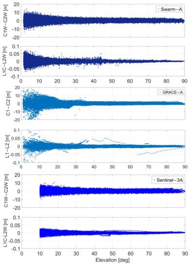
Figure 5.
Elevation-dependent GF pseudo-range and carrier-phase measurement residuals for Swarm-A (top), GRACE-A (middle), and Sentinel-3A (below).
The calculated GF pseudo-range noises of the Swarm-A, GRACE-A, and Sentinel-3A GPS data are 1.88 m, 1.97 m, and 1.46 m, respectively, and the carrier-phase measurement noises are 0.0098 m, 0.0041 m, and 0.0022 m, respectively. Figure 5 indicates that the measurement noises of GRACE-A and Sentinel-3A tend to be much smaller than those of Swarm-A. This is due to the stronger signal-to-noise ratio (SNR) of GRACE-A. The pseudorange noise is closely related to the SNR or the carrier-to-noise ratio (C/N0). Signals with weaker signal strengths have larger tracking noise. In addition, the Sentinel-3A spaceborne observations were sampled at a cut-off elevation of 10°, resulting in a much lower noise level. According to the variance-covariance propagation law, if the noise levels for L1 and L2 are assumed to be the same, we can calculate that the L1 and L2 measurement noises are 0.0069 m, 0.0029 m, and 0.0016 m for the Swarm-A, GRACE-A, and Sentinel-3A spaceborne data, respectively. Therefore, the average value of 0.0049 m was used as the calibration noise for our subsequent observation simulation.
4.2. BDS/LEO Combined POD during a Quiet Period of Solar Activity
The BDS-LEO combined POD was calculated with the five designed LEO constellations. In total, six schemes were tested: (S1) the BDS POD with the regional network shown in Figure 3; (S2) the Walker 2/1/0 LEO constellation added to S1; (S3) the Walker 6/2/1 LEO constellation added to S1; (S4) the Walker 12/3/1 LEO constellation added to S1; (S5) the Walker 24/4/2 LEO constellation added to S1; and (S6) the Walker 60/6/4 LEO constellation added to S1. The BDS orbital differences between the estimated orbits and the “reference” are shown in Figure 6. The Swarm POD residuals during the quiet period of solar activity were calculated and added to the simulated spaceborne observations.
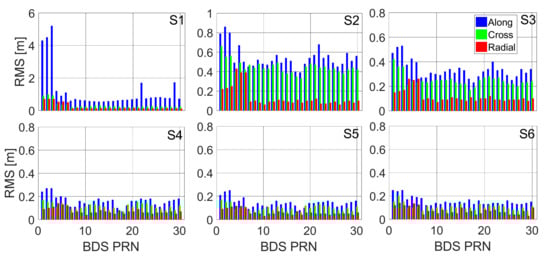
Figure 6.
The BDS POD results from S1 to S6 schemes, shown from subplots left to right.
Figure 6 indicates that the average orbital accuracies of the BDS GEO satellites for the along, cross, and radial components with the regional network are 4.5 m, 1.1 m, and 0.80 m, respectively, and that the orbital accuracies of the IGSO and MEO satellites for the three components are 1.1 m, 0.61 m, and 0.44 m. When the Walker 12/3/1 LEO constellation is included, the orbital accuracy is considerably improved, especially for the along component of the GEO satellites, which is improved to 0.28 m, while the cross and radial components reach 0.24 m and 0.1 m, respectively. Meanwhile, the orbital accuracies of the IGSO and MEO satellites are improved to 0.23 m, 0.18 m, and 0.09 m for the three components. However, the BDS orbital accuracy is not continuously improved with the increasing number of LEO satellites from 12 to 24; the accuracy with the Walker 60/6/4 constellation is nearly the same as that derived with the Walker 12/3/1 constellation.
To further understand the LEO satellite enhancement of the BDS orbit determination, the orbital dilution of precision (ODOP) for the BDS was calculated. The calculation of the ODOP is similar to the position dilution of precision (PDOP) for ground stations. The ODOP in this study indicates the geometric strength of the BDS tracked by LEO satellites and ground stations. The better the geometry structure, the smaller the ODOP. The ODOP can be calculated based on the below algorithms:
where , , and represent the coordinates in three directions of the ground station, LEO satellite, and GNSS satellite, respectively. is the geometry distance vector from the ground station to a GNSS satellite and is similar for . Figure 7 shows the ODOP values of the G05/G10/C02/C03/C06/C11 satellites.
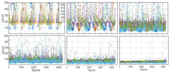
Figure 7.
The ODOP values of G05/G10/C02/C03/C06/C11 satellites with respect to the regional ground stations; the regional network and W2/1/0 LEOs; the regional network and W6/2/1 LEOs; the regional network and W12/3/1 LEOs; the regional network and W24/4/2 LEOs; and the regional network and W60/6/4 LEOs, which are shown from subplots left to right. The epoch time interval is 10 s.
The ODOP decreases with increasing numbers of LEO satellites; however, the BDS orbital accuracy does not improve accordingly. The average ODOP value for each BDS satellite decreases moderately as the LEO number increases from 12 to 60 and the orbital error approaches a stable value. In addition, the LEO orbit is unknown; only the ground network is fixed. The improvements of the BDS and LEO orbits are both restricted by the limited number of ground stations.
4.3. GNSS/LEO Combined POD during a Solar Storm
A geomagnetic storm, which was triggered by a coronal mass ejection that broke out on 7–8 September 2017, was analyzed to investigate the impact of spaceborne observational errors on the BDS POD [35]. Studies show that the quality of the LEO constellations, i.e., the Swarm constellation, are severally degraded during the main phases of storms and that the maximum degradation of the orbit accuracy can be over 10 cm [18]. The main reason for the Swarm orbit accuracy degradation is the enhanced thermospheric mass density at the Swarm altitude, which increased the atmospheric drag for the LEO satellites. In addition, high-order ionospheric residual errors negatively affect the BDS/LEO combined POD. In the POD processing, if most observational errors have been carefully corrected by modeling or precise data processing strategies, the residuals will be in a normal distribution and close to the measurement noise level. Therefore, residuals are important indicators to assess the positioning or orbit determination errors. In this study, the Swarm-A and GRACE-A satellite POD residuals calculated with the geometric approach were first analyzed during the 7–9 September 2017 geomagnetic storm.
The IF carrier-phase residuals of the Swarm-A and GRACE-A spaceborne GPS observations for days 007–009 are shown in Figure 8. The carrier-phase residuals of GRACE-A are much lower than those of Swarm-A, likely as a result of the much smaller carrier-phase measurement noise of GRACE-A, as seen in Figure 5. Therefore, considering the worst case, the Swarm-A observation residuals were used and applied in the observation simulation. In addition, the impaction times of the solar storm on the Swarm-A POD were 2:00–10:00 Universal Time (UT) and 15:20–23:00 UT, while the impaction times were 04:00–14:00 UT and 18:00–09:00 UT (+24 h) on 8 September 2017 for the GRACE-A POD. The initial impaction times are different for the two LEO satellites primarily because they are located on different orbital planes and at different altitudes. Therefore, it is necessary to consider the differences in the initial impaction times for the designed LEO satellites when adding the actual-observed residuals to the simulated spaceborne observations. Here, we first selected an LEO satellite on each orbital plane and then added the actual residuals calculated from the data on 8 September. The residuals added to the other satellites in this plane were lagged for a period of time depending on the specific satellite. For example, in the Walker 12/3/1 constellation, it takes 84 min for an LEO satellite to circle the Earth; the lag time for two adjacent satellites on each orbital plane is therefore 84 min/4 = 21 min. For the Walker 2/1/0 constellation, according to the number of LEO satellites tracking the BDS satellites, which is shown in Figure 9, only one LEO satellite at most simultaneously tracks each BDS satellite. The observation residuals of Swarm-A at 00:00 UT on 8 September start to be added to an LEO satellite when it flies over 30° E longitude and the observation residuals 49 min later are added to the next LEO satellite according to the lag time.
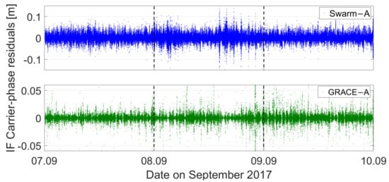
Figure 8.
IF carrier-phase measurement residuals for the Swarm-A and GRACE-A spaceborne GPS observations.
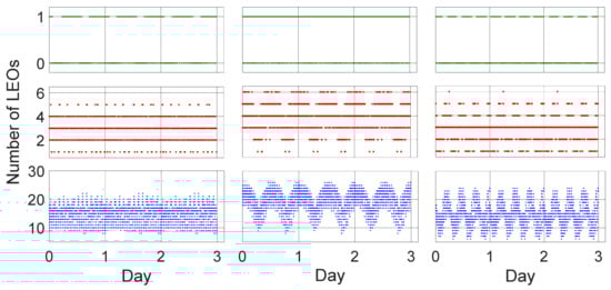
Figure 9.
The number of tracked BDS C02 (left three subplots)/C06 (middle three subplots)/C11 (right three subplots) satellites by LEO satellites. The green, red, and blue dots represent the W2/1/0, W12/3/1, and W60/6/4 LEO constellation, respectively.
Note that the actual effect of the solar storm on the BDS/LEO combined POD is very difficult to simulate because the impaction time and magnitude are very irregular and almost impossible to accurately simulate. This study makes an approximate simulation and the only certainty is that the initial impaction times for the LEO satellites in different orbital planes or at different altitudes are different. To better understand the influences of the spaceborne observational errors on the BDS POD, a purely geometrical approach was adopted here without considering any of the satellite dynamics. The orbit determination results are shown in Figure 10. Figure 10 displays the POD error time series for the C02, C06, and C11 satellites.
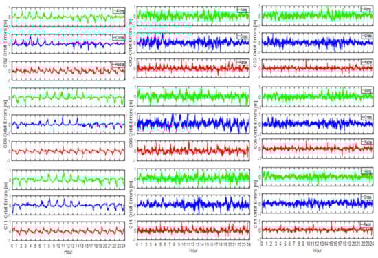
Figure 10.
Orbit differences between the estimated and the “references” of C02/C06/C11 satellites for scheme S2, S4, and S6, respectively.
We can see from Figure 10 that the BDS orbits are severely affected by the spaceborne observational errors in the BDS/LEO combined POD mode. In the S2 scheme, each BDS satellite is observed by only one LEO satellite, as can be seen in Figure 9; therefore, the orbit of each BDS satellite is directly affected by the observational errors onboard this one LEO satellite. The 3D RMS values shown in Table 5 for the C02, C06, and C11 satellites are 1.18 m, 1.07 m, and 0.75 m, respectively.
Table 5.
Statistics of the ODOP and orbital 3D RMS values.
In the Walker 12/3/1 constellation, the BDS C02, C06, and C11 satellites are tracked simultaneously by two to five LEO satellites (Figure 9). Considering the times that the observational errors start to be added to each LEO satellite are different, the time that the POD starts to be impacted by large observational errors is different for each BDS satellite, resulting in different magnitude large POD errors and different impaction times. Even though part of the observational errors can be compensated for by a combined adjustment with different LEO satellites, they cannot be completely compensated for because of the small number of visible LEO satellites. The POD errors are nearly comparable to those in the S2 scheme, as can be seen in Figure 10.
When the number of LEO satellites reaches 60, all the different types of BDS satellites can be tracked by 10–25 LEO satellites at the same time (see Figure 9). The fast change in the LEO geometric configuration, as well as the large number of LEO satellites involved in the adjustment of the combined POD, contribute to the improvement in the BDS orbit accuracy and the large observational errors are effectively reduced. The BDS orbit solutions are the best of the three schemes, as shown in Figure 10. The RMS values are 0.60 m, 0.43 m, and 0.44 m for the C02, C06, and C11 satellites, respectively (Table 5).
There is another reason for the results shown in Figure 10. As explained before, the BDS POD results are associated with the ODOP value of the LEO constellation. However, they are also closely related to the spaceborne and ground-based observational errors. Note that more careful modeling or precise processing can be done to account for these observational errors. In this study, we do not try to eliminate these errors; instead, we attempt to weaken them by using a large LEO constellation. From Table 5, we can see that the average ODOP value of the three types of BDS satellites derived from the S4 scheme is smaller than that from the S2 scheme; however, the BDS orbit solutions for the two schemes show nearly no difference. This can be explained by investigating the inner accuracy, which is computed as , where the calculation of the coefficient matrix is identical to that of the ODOP and both are related to the geometric strength, and the variance of the unit weight is calculated based on the residuals. Larger observational errors will result in larger amplitude residuals and, in turn, larger . Considering the POD accuracy is co-affected by both the ODOP and the observational errors, the BDS orbit solutions in the S4 scheme present identical results to those in the S2 scheme and the lowest ODOP and smallest observational errors after the adjustment of the S6 scheme show the best solutions.
5. Discussion
This study demonstrates that the BDS POD accuracy with a regional network can be effectively improved to the cm level by a large LEO constellation with as many as 10–25 visible LEO satellites. However, the spaceborne observations can be seriously affected by an extreme space weather event, such as a solar storm. The real impaction time and magnitude of a solar storm on LEO satellites on different altitude and orbit planes is different through a calculation with real observations. This gives us a reference for the simulation of spaceborne observations when considering the observation errors. However, the real situation is much more complicated as the effect of a solar storm on a global operational capability LEO constellation used for, i.e., navigation augmentation is very irregular and impossible to be precisely simulated. It is just an approximate simulation in this study and demonstrates that an LEO constellation with about 10–25 visible LEO satellites is sufficient to reliably reduce or mitigate the observation errors on BDS POD in a combined adjustment procedure. For the real impaction magnitude and time, we can only hope to resolve these issues with real spaceborne observations from a global LEO constellation in the future.
6. Conclusions
This paper discussed two key issues with regard to a large LEO-constellation-augmented BDS POD with simulated spaceborne and ground observations. BDS-3 and five types of LEO constellations, namely the Walker 2/1/0, 6/2/1, 12/3/1, 24/4/2, and 60/6/4 constellations, were designed. The actual spaceborne measurement noise level tends to be different from that of the ground receivers and needs to be analyzed and calibrated. Therefore, the measurement noise from Swarm-A, GRACE-A, and Sentinel-3A spaceborne observations were calibrated for by observation simulations with different LEO constellations.
Another issue addressed here is that of the spaceborne observational errors. Unlike ground observations, in which the observational errors primarily result from atmospheric delay and the multipath effect, spaceborne observation errors are primarily caused by ionospheric scintillations or thermal atmosphere, which cannot be completely eliminated using the conventional POD method. This study examines the effect of large spaceborne observational errors on the BDS POD augmented by different LEO constellation configurations. Using an experiment, the actual observation residuals calculated from the Swarm-A and GRACE-A observations were analyzed and it was found that the impaction times and magnitudes of a solar storm varied for LEO satellites at different altitudes and in different orbital planes. The BDS orbit accuracy can be seriously degraded by spaceborne observational errors when using a Walker 12/3/1 LEO-constellation-augmented BDS POD. For a Walker 60/6/4 constellation, the BDS satellites can be tracked by as many as 10–25 LEO satellites at one time and both the rapid change in an LEO satellite and the many LEO spaceborne observations involved in the adjustment can effectively compensate for and reduce the spaceborne observational errors. The results indicate that even 3–4 LEO satellites are sufficient to augment the BDS POD with a regional ground network, allowing the 3D orbit accuracy of GEO satellites to reach 20–40 cm. However, a large LEO constellation with 10–25 LEO satellites tracking the BDS satellites is still necessary in the case of large spaceborne observational errors caused by extreme space weather, i.e., solar storms.
Author Contributions
M.L., T.X. and H.G. conceived the experiments. M.G. and Z.F. processed the data and drew the pictures. H.Y. and F.G. investigated the results. M.L. wrote the whole manuscript. All authors have read and agreed to the published version of the manuscript.
Funding
This study was funded by the National Key Research and Development Program of China (2020YFB0505800), National Natural Science Foundation of China (grant number 41874032), and Postdoctoral Science Foundation of China (2021M691902).
Institutional Review Board Statement
Not applicable.
Informed Consent Statement
Not applicable.
Acknowledgments
We are very grateful to the International GNSS Service (IGS) for providing the multi-GNSS precise orbit and clock products (ftp://igs.ign.fr/pub/igs/ accessed on 20 June 2021). The Swarm, GRACE, and Sentinel-3 spaceborne GPS data provided by the European Space Agency (ESA) as part of the Copernicus program and GFZ are greatly acknowledged.
Conflicts of Interest
The authors declare no conflict of interest.
References
- Dai, X.; Ge, M.; Lou, Y.; Shi, C.; Wickert, J.; Schuh, H. Estimating the yaw-attitude of BDS IGSO and MEO satellites. J. Geod. 2015, 89, 1005–1018. [Google Scholar] [CrossRef]
- Guo, J.; Chen, G.; Zhao, Q.; Liu, J.; Liu, X. Comparison of solar radiation pressure models for BDS IGSO and MEO satellites with emphasis on improving orbit quality. GPS Solut. 2017, 21, 511–522. [Google Scholar] [CrossRef] [Green Version]
- Montenbruck, O.; Steigenberger, P.; Hugentobler, U. Enhanced solar radiation pressure modeling for Galileo satellites. J. Geod. 2014, 89, 283–297. [Google Scholar] [CrossRef]
- Zhang, Q.; Zhu, Y.; Chen, Z. An In-Depth Assessment of the New BDS-3 B1C and B2a Signals. Remote Sens. 2021, 13, 788. [Google Scholar] [CrossRef]
- Guo, F.; Li, X.; Zhang, X.; Wang, J. Assessment of precise orbit and clock products for Galileo, BeiDou, and QZSS from IGS Multi-GNSS Experiment (MGEX). GPS Solut. 2017, 21, 279–290. [Google Scholar] [CrossRef]
- Joerger, M.; Gratton, L.; Pervan, B.; Cohen, C.E. Analysis of Iridium-Augmented GPS for Floating Carrier Phase Positioning. Navigation 2010, 57, 137–160. [Google Scholar] [CrossRef]
- Li, B.; Ge, H.; Ge, M.; Nie, L.; Shen, Y.; Schuh, H. LEO enhanced Global Navigation Satellite System (LeGNSS) for real-time precise positioning services. Adv. Space Res. 2019, 63, 73–93. [Google Scholar] [CrossRef]
- Ge, H.; Li, B.; Ge, M.; Zang, N.; Nie, L.; Shen, Y.; Schuh, H. Initial Assessment of Precise Point Positioning with LEO Enhanced Global Navigation Satellite Systems (LeGNSS). Remote Sens. 2018, 10, 984. [Google Scholar] [CrossRef] [Green Version]
- Li, X.; Zhang, K.; Ma, F.; Zhang, W.; Bian, L. Integrated Precise Orbit Determination of Multi-GNSS and Large LEO Constel-lations. Remote Sens. 2019, 11, 2514. [Google Scholar] [CrossRef] [Green Version]
- Li, X.; Ma, F.; Li, X.; Lv, H.; Bian, L.; Jiang, Z.; Zhang, X. LEO constellation-augmented multi-GNSS for rapid PPP convergence. J. Geod. 2019, 93, 749–764. [Google Scholar] [CrossRef]
- Rabinowitz, M.; Parkinson, B.; Cohen, C.; O’Connor, M.; Lawrence, D. A system using LEO telecommunication satellites for rapid acquisition of integer cycle ambiguities. In Proceedings of the IEEE 1998 Position Location and Navigation Symposium (Cat. No. 98CH36153), Palm Springs, CA, USA, 20–23 April 1996; pp. 137–145. [Google Scholar] [CrossRef]
- Skone, S.H. The impact of magnetic storms on GPS receiver performance. J. Geod. 2001, 75, 457–468. [Google Scholar] [CrossRef]
- Hu, Y.; Cai, Z. Influences of Space Weather Events on the Spacecraft. Adv. Meteorol. Sci. Technol. 2011, 1, 13–17. [Google Scholar]
- Janssen, V. Likely impact of the approaching solar maximumon GNSS surveys: Be alert but not alarmed. In Proceedings of the 17th Association of the Public Authority Surveyors Conference (APAS2012), Wollongong, Australia, 19–21 March 2012. [Google Scholar]
- Cerruti, A.P.; Kintner, P.M.; Gary, D.; Lanzerotti, L.J.; De Paula, E.R.; Vo, H. Observed solar radio burst effects on GPS/Wide Area Augmentation System carrier-to-noise ratio. Space Weather 2006, 4, 10006. [Google Scholar] [CrossRef]
- Chen, Z.; Gao, Y.; Liu, Z. Evaluation of solar radio bursts’ effect on GPS receiver signal tracking within International GPS Service network. Radio Sci. 2005, 40, 3012. [Google Scholar] [CrossRef]
- Kintner, P.M.; Ledvina, B.M.; De Paula, E.R. GPS and ionospheric scintillations. Space Weather 2007, 5, 09003. [Google Scholar] [CrossRef]
- Zhang, K.; Li, X.; Xiong, C. The Influence of Geomagnetic Storm of 7September 2017 on the Swarm Precise Orbit Determination. J. Geophys. Res. Space Phys. 2019, 124, 6971–6984. [Google Scholar] [CrossRef]
- Walker, J.G. Satellite constellations. J. Br. Interplanet. Soc. 1984, 37, 559–572. [Google Scholar]
- Förste, C.; Bruinsma, S.; Shako, R.; Marty, J.-C.; Flechtner, F.; Abrykosov, O.; Dahle, C.; Lemoine, J.-M.; Neumayer, K.-H.; Biancale, R. EIGEN-6—A New Combined Global Gravity Field Model Including GOCE Data from the Collaboration of GFZ Potsdam and GRGS Toulouse (Geophysical Research Abstracts Vol.13, EGU2011-3242-2, 2011); General Assembly European Geosciences Union: Vienna, Austria, 2011. [Google Scholar]
- Petit, G.; Luzum, B. IERS Conventions 2010. No.36 in IERS Technical Note; Verlag des Bundesamts für Kartographie und Geodäsie: Frankfurt am Main, Germany, 2010. [Google Scholar]
- Lyard, F.; Lefevre, F.; Letellier, T.; Francis, O. Modelling the global ocean tides: Modern insights from FES2004. Ocean Dyn. 2006, 56, 394–415. [Google Scholar] [CrossRef]
- Arnold, D.; Meindl, M.; Beutler, G.; Dach, R.; Jggi, A. CODE’s new solar radiation pressure model for GNSS orbit determination. J. Geod. 2015, 89, 775–791. [Google Scholar] [CrossRef] [Green Version]
- Berger, C.; Biancale, R.; Ill, M.; Barlier, F. Improvement of the empirical thermospheric model DTM: DTM94—A comparative review of various temporal variations and prospects in space geodesy applications. J. Geod. 1998, 72, 161–178. [Google Scholar] [CrossRef]
- Kouba, J.; Héroux, P. Precise Point Positioning Using IGS Orbit and Clock Products. GPS Solut. 2001, 5, 12–28. [Google Scholar] [CrossRef]
- Li, M.; He, K.; Xu, T.; Lu, B. Robust adaptive filter for shipborne kinematic positioning and velocity determination during the Baltic Sea experiment. GPS Solut. 2018, 22, 81. [Google Scholar] [CrossRef]
- Zhang, B.; Chen, Y.; Yuan, Y. PPP-RTK based on undifferenced and uncombined observations: Theoretical and practical aspects. J. Geod. 2018, 93, 1011–1024. [Google Scholar] [CrossRef]
- Saastamoinen, J. Atmospheric Correction for the Troposphere and Stratosphere in Radio Ranging Satellites. In Use of Aritificial Satellites for Geodesy; Wiley: Hoboken, NJ, USA, 1972; Volume 15, pp. 247–251. [Google Scholar]
- Boehm, J.; Niell, A.; Tregoning, P.; Schuh, H. Global Mapping Function (GMF): A new empirical mapping function based on numerical weather model data. Geophys. Res. Lett. 2006, 33, 07304. [Google Scholar] [CrossRef] [Green Version]
- Zhang, B.; Ou, J.; Yuan, Y.; Li, Z. Extraction of line-of-sight ionospheric observables from GPS data using precise point positioning. Sci. China 2012, 55, 1919–1928. [Google Scholar] [CrossRef]
- Montenbruck, O.; Steigenberger, P.; Hauschild, A. Broadcast versus precise ephemerides: A multi-GNSS perspective. GPS Solut. 2015, 19, 321–333. [Google Scholar] [CrossRef]
- Friis-Christensen, E.; Lühr, H.; Knudsen, D.; Haagmans, R. Swarm—An Earth Observation Mission investigating Geospace. Adv. Space Res. 2008, 41, 210–216. [Google Scholar] [CrossRef]
- Montenbruck, O.; Hackel, S.; Jäggi, A. Precise orbit determination of the Sentinel-3A altimetry satellite using ambiguity-fixed GPS carrier phase observations. J. Geod. 2018, 92, 711–726. [Google Scholar] [CrossRef] [Green Version]
- Wagner, C.; McAdoo, D.; Klokočník, J.; Kostelecký, J. Degradation of Geopotential Recovery from Short Repeat-Cycle Orbits: Application to GRACE Monthly Fields. J. Geod. 2006, 80, 94–103. [Google Scholar] [CrossRef]
- Tassev, Y.; Velinov, P.I.; Tomova, D.; Mateev, L. Analysis of extreme solar activity in early September 2017: G4—Severe geomagnetic storm (07-08.09) and GLE72 (10.09) in solar minimum. Comptes Rendus l’Acade’mie Bulg. Sci. 2017, 70, 1437–1444. [Google Scholar]
Publisher’s Note: MDPI stays neutral with regard to jurisdictional claims in published maps and institutional affiliations. |
© 2021 by the authors. Licensee MDPI, Basel, Switzerland. This article is an open access article distributed under the terms and conditions of the Creative Commons Attribution (CC BY) license (https://creativecommons.org/licenses/by/4.0/).