Article

Cascaded Microwave Frequency Transfer over 300-km Fiber Link with Instability at the 10−18 Level

1
National Time Service Center, Chinese Academy of Sciences, Xi’an 710600, China
2
Key Laboratory of Time and Frequency Primary Standards, Chinese Academy of Sciences, Xi’an 710600, China
3
School of Astronomy and Space Science, University of Chinese Academy of Sciences, Beijing 100049, China
*
Author to whom correspondence should be addressed.
Remote Sens. 2021, 13(11), 2182; https://doi.org/10.3390/rs13112182
Submission received: 12 April 2021 / Revised: 20 May 2021 / Accepted: 25 May 2021 / Published: 3 June 2021
(This article belongs to the Special Issue Advanced RF Sensors and Remote Sensing Instruments)

Abstract

:
Comparing and synchronizing atomic clocks between distant laboratories with ultra-stable frequency transfer are essential procedures in many fields of fundamental and applied science. Existing conventional methods for frequency transfer based on satellite links, however, are insufficient for the requirements of many applications. In order to achieve high-precision microwave frequency transfer over a thousand kilometers of fiber and to construct a fiber-based microwave transfer network, we propose a cascaded system for microwave frequency transfer consisting of three 100-km single-span spooled fiber links using an improved electronic phase compensation scheme. The transfer instability measured for the microwave signal reaches 1.1 × 10¹⁴ at 1 s and 6.8 × 10¹⁸ at 105 s, which agrees with the root-sum-square of each span contribution. It is feasible to extend the length of the fiber-based microwave frequency transfer up to 1200 km using 4 stages of our cascaded system, which is still sufficient to transfer modern cold atom microwave frequency standards. Moreover, the transfer instability of 9.0 × 10⁻¹⁵ at 1 s and 9.0 × 10⁻¹⁸ at 105 s for a 100-MHz signal is achieved. The residual phase noise power spectral density of the 300-km cascaded link measured at 100-MHz is also obtained. The rejection frequency bandwidth of the cascaded link is limited by the propagation delay of one single-span link.

Graphical Abstract

1. Introduction

Long-haul and high-precision frequency transfer between distant laboratories plays a crucial role in numerous fields of fundamental and applied science, such as time and frequency metrology [1,2], fundamental physics [3,4], and geodesy [5]. The synchronization of distributed systems (such as phased-array radio telescopes [6,7,8], very long baseline interferometry (VLBI) [9,10], and multistatic radar systems [11,12]) are also applications. At present, remote frequency comparison and synchronization is usually performed based on satellite links, including two-way satellite time and frequency transfer (TWSTT) as well as global positioning system (GPS) carrier-phase observations. However, owing to the non-reciprocity of links, these methods are limited by an instability of 10−15 after one day and do not provide the short-term stability necessary for synchronization applications [13]. Consequently, frequency transfer over satellite links is insufficient for many application requirements. Fortunately, taking advantage of the low loss, high reliability and active phase stabilization potential of optical fiber, high stability has been demonstrated for direct optical frequency transfer [14,15,16,17] and radio-frequency (RF) transmission using the intensity modulation of an optical carrier [18,19,20,21,22,23,24,25] over fiber links. The instability of fiber-based optical frequency transfer reached the 10−20 level at 104 s over an urban fiber of more than 100 km [16,17], while microwave frequency transfer has presented an instability of 10−19 level at one day over an urban fiber of about 80 km [19,20]. In addition, simultaneous dissemination of time (1 PPS) and frequency (10/100 MHz) signals generated by atomic clocks over fiber have also demonstrated fairly low residual instability [26,27].
There are two main limitations to the achievable length of distance extension of fiber-based frequency transfer. In the first place, the bandwidth f c of the link noise compensation is limited by the propagation delay τ of the fiber [28,29], which is simplified as f c < 1 / 4 τ . In the second place, frequency transfer instability is dominated by the signal-to-noise ratio (SNR) of the output-detected signal, which is limited by the attenuation of the fiber link. In particular, in the case of microwave frequency transmission using the intensity modulation of an optical carrier, the power of the microwave signal detected at the end of the fiber link is attenuated by twice of link attenuation (expressed in dB) [30], and the performance of link noise compensation is degraded by the chromatic dispersion and polarization mode dispersion (PMD) effect of fiber [19,31]. Therefore, compared with the single-span transfer, the cascaded transfer with independent link noise compensation for each short segment is more suitable for ultra-long-distance fiber-based microwave frequency transfer. The earliest reported study of cascaded microwave frequency transfer has demonstrated an instability of 6 × 10⁻¹⁴ at 1 s and 5 × 10⁻¹⁷ at one-half day over 204-km urban fiber link consisting of two single-span links [32]. In 2016, a 1-GHz signal was transferred through 430 km of urban fiber link with an instability of 1.94 × 10⁻¹³ at 1 s and 1.34 × 10⁻¹⁶ at 104 s using a cascaded system consisting of two single-span links, which is a record distance of fiber-based microwave frequency transfer [33].
The National Time Service Center (NTSC) of the Chinese Academy of Sciences (CAS) undertakes the task to generate, maintain, and transmit the national standard of time (Beijing Time), which has already demonstrated an ultra-stable microwave frequency transfer over a 112-km urban fiber link with an instability of 4.2 × 10⁻¹⁵ at 1 s and 1.6 × 10⁻¹⁸ at one day [25]. In this work, to achieve microwave frequency transfer with high precision over a thousand kilometers of fiber and construct fiber-based microwave transfer network, we first used fiber spools to perform a microwave frequency transfer experiment with a cascaded system. Subsequently, we investigated the ultra-stable microwave frequency transfer over a 300-km fiber link with the cascaded system, which is composed of three single-span links. The frequency transfer instability of each span, as well as of the cascaded link, is investigated. The 300-km cascaded link reached an instability of 1.1 × 10⁻¹⁴ at 1 s and 6.8 × 10⁻¹⁸ at 105 s. The residual phase noise of the entire link was also measured. The bandwidth of the link noise compensation was unaffected by the length of the entire link.

2. Materials and Methods

2.1. Principle of Frequency Transfer System

In fiber-based microwave frequency transfer, two approaches of phase compensation exist: optical path compensation (OPC) and electronic phase compensation (EPC) [34]. Although the OPC approach can achieve better transfer instability, the compensation actuator, which consists of a piezo-electric fiber stretcher and thermally-controlled fiber spool [31,35], is complex and has small dynamic range, which is inconvenient for extensive applications. On the contrary, the EPC approach has strong adaptability and little PMD fluctuation effect due to the voltage-controlled oscillator (VCO) used as an actuator [25], except that the performance is slightly poorer than that of the OPC approach. Therefore, in order to broaden the application range of the fiber-based microwave frequency transfer system, we adopted the EPC scheme.
For fiber-based frequency transfer, the phase noise induced by the fiber link was measured by comparing the round-trip signal with the reference signal and compensating it in real time. In a typical implementation of microwave transfer over fiber based on the EPC approach, the forward and backward signals have the same frequency, which leads to the transfer instability being limited by Brillouin backscattering and parasitic reflections along the link, especially for long-distance fiber with more connectors and splices. For this reason, to suppress the influence of the backscattering and parasitic reflections, an improved frequency transfer system based on the EPC approach was designed with two different microwave frequencies for the forward and backward signals. The schematic of the fiber-based frequency transfer system is shown in Figure 1.
As shown in Figure 1, the reference signal V r can be expressed as:
V r sin ( ω r t + φ r )
where ω r and φ r stand for the angular frequency and the initial phase of the reference signal, respectively. The frequency signal V 0 is generated by a VCO, which can be expressed as:
V 0 sin ( ω 0 t + φ 0 )
where ω 0 and φ 0 represent the angular frequency and the initial phase of V 0 , respectively. Note that Equations (1) and (2) are derived without considering the random phase noise of the frequency signal.
V 0 modulates the intensity of the laser carrier and transmits it along the fiber link to the receiving (RX) end. At the RX end, the one-way trip signal detected by a fast photodiode (PD2) can be expressed as:
V R X sin [ ω 0 ( t τ f ) + φ 0 ]
where τ f represents the forward propagation delay of the fiber. V R X is frequency-divided by 4 with a low-noise frequency divider to modulate the intensity of the second laser carrier that is used to generate the backward signal. At the transmitting (TX) end, the backward signal is detected by the second photodiode (PD1), which can be expressed as:
V b a c k sin [ ω 0 ( t τ f τ b ) / 4 + φ 0 / 4 ] ,
where τ b represents the backward propagation delay of the fiber, and V b a c k carries the round-trip phase fluctuations accumulated along the fiber.
In the phase comparison system, the reference signal V r is power-split into two arms. In the first arm, V r is mixed with V 0 by a double-balanced mixer (DBM) to generate a frequency difference between V 0 and V r . The latter signal is frequency-divided by 4 with a low-noise frequency divider to generate a signal that can be expressed as:
V 1 sin [ ( ω 0 ω r ) t / 4 + ( φ 0 φ r ) / 4 ] .
In the second arm, V r is mixed with V b a c k by a DBM to generate a frequency difference between V r and V b a c k , which can be expressed as:
V 2 sin [ ( 4 ω r ω 0 ) t / 4 + ( 4 φ r φ 0 + ω 0 τ f + ω 0 τ b ) / 4 ] .
V 1 is phase-compared with V 2 using a saturated DBM to produce an error signal including the noise of link and VCO, which can be expressed as:
V e sin [ ( 2 ω 0 5 ω r ) t / 4 + ( 2 φ 0 5 φ r ω 0 τ f ω 0 τ b ) / 4 ] .
The error signal is processed in a loop filter F ( p ) and used to feedback the VCO. Thus, it can be inferred that
{ ω 0 = 5 ω r / 2 ω 0 ( τ f + τ b ) = 2 φ 0 5 φ r .
As a result, the frequency signal V R X at the RX end becomes:
V R X sin [ 5 ω r ( t τ f τ b 2 ) / 2 + 5 φ r / 2 ] .
We assume that the fiber link is reciprocal, that is τ f = τ b = τ . Thus, Equation (9) is reformulated as:
V R X sin ( 5 ω r t / 2 + 5 φ r / 2 ) ,
which becomes coherent with the reference signal V r , and the phase fluctuations due to the fiber link are canceled. According to Equations (2) and (8), and the reciprocity assumption of the link, the frequency signal V 0 becomes:
V 0 sin [ 5 ω r ( t + τ ) / 2 + 5 φ r / 2 ] .
By comparing the phase of V R X to V r and V R X to V 0 in closed loop, the frequency transfer performance of compensation link and free link can be measured.
According to the above analysis, the link noise can be compensated with the scheme shown in Figure 1, as long as the frequency of the transmitted signal V 0 is roughly 2.5 times that of the reference signal V r . In the practical implementation of cascade transfer system over urban fiber links, it is preferred to use different frequencies of the transmitted signal for adjacent single-span links to suppress the influence of microwave leakage. In view of this, we designed two kinds of frequency transfer systems in different frequencies, in which the frequencies of reference signal and transmission signal were 4 GHz and 10 GHz, respectively (we called it 10-GHz transfer system), and the other frequencies were 3.6 GHz and 9 GHz, respectively (we called it 9-GHz transfer system).

2.2. Experimental Setup

2.2.1. 10-GHz and 9-GHz Transfer Systems

Figure 2 shows the detailed scheme of the 10-GHz transfer system over a 100-km fiber spool. The 4-GHz reference signal V r was generated by a phase-locked dielectric resonant oscillator (PDRO), which was phase-locked on the 100-MHz signal generated by a passive Hydrogen maser (PHM) (Vremya-Ch, Nizhny Novgorod, Russia, VCH-1008). The transmission signal at 10-GHz was provided by a different PDRO phase-locked to a low-noise 100-MHz oven-controlled crystal oscillator (OCXO), which was modulated to the laser intensity by a Mach–Zehnder modulator (MZM) and transmitted to the RX end over the fiber link. The 10-GHz PDRO and 100-MHz OCXO were contained in an OSC-10GHz module, which is equivalent to the VCO in Figure 1. At the RX end, the incoming 10-GHz signal was detected by a fast photodiode PD2 amplified by a low-noise amplifier (LNA) (Analog Devices, Wilmington, USA, HMC903LP3E), and frequency-divided by 4 with a low-noise frequency divider (Analog Devices, Wilmington, USA, HMC365) to generate a 2.5-GHz signal. The 2.5-GHz signal modulated the intensity of the second laser by MZM to transmit a backward signal to the TX end through the same fiber. The backward signal was detected by another fast photodiode PD1. The output signal V b a c k of PD1 was amplified by LNA (Qorvo, Greensboro, USA, TQP3M9008) and sent to a phase comparison system. By comparing the phases of V r , V 0 , and V b a c k (see Figure 1), the phase comparison system generated an error signal, which was fed to an active loop filter to provide a control signal. The fiber link noise will be compensated by adjusting the frequency of the 100-MHz OCXO in the OSC-10GHz module. The loop bandwidth of the compensation system was less than 500 Hz.
The 9-GHz distribution system is highly similar to the 10-GHz system, where the 4-GHz and 10-GHz components need to be replaced by 3.6-GHz and 9-GHz components, respectively.
In the transfer system, each laser was a continuous wave tunable digital supermode distributed Bragg reflector (DS-DBR) laser to be used in the C-band window covering the 1528-nm to 1563-nm range. The wavelength can be controlled by a 50-GHz (0.4-nm) International Telecommunications Union (ITU) wavelength grid. In order to overcome the influence of coherent Rayleigh backscatter noise, 0.4-nm difference was set between the wavelength of the laser at the TX end and the laser at the RX end, which were 1550.92 nm and 1550.52 nm, respectively. In addition, to reduce the effect caused by the chromatic dispersion (~17 ps/nm/km) of fiber on the frequency transfer, a dispersion-compensating fiber (DCF) module with a loss of about 10 dB was inserted at the TX end. Behind the DCF, a bidirectional erbium-doped fiber amplifier (Bi-EDFA) with a gain of about 10 dB was used to compensate the optical loss caused by the DCF and to improve the SNR at detection. As demonstrated previously [25], the PMD effect has a slight influence on the fiber-based microwave frequency transfer using the EPC approach. Therefore, there was no use of polarization scramblers to average out the PMD effect.

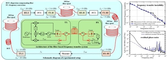
2.2.2. Cascaded Microwave Frequency Transfer

A cascaded system of microwave transfer was established by connecting three single-span systems with two frequency converters. The cascaded link was composed of three 100-km fiber spools. The whole system was placed within the same laboratory. The laboratory temperature was about 25 ± 1 °C and the period of temperature fluctuations caused by air-conditioning was about 40 min. The first single-span link was a 10-GHz transfer system, and the second and third single-span links were both 9-GHz transfer systems. In the second span, the DCF and Bi-EDFA were not used. The schematic diagram of the constructed cascaded transfer system is depicted in Figure 3. In order to output a 100-MHz signal at the end of the cascaded system, a low-noise 100-MHz OCXO was phase-locked to the received 9-GHz signal at the RX end of the third span via a 9-GHz PDRO.
In order to evaluate the frequency transfer performance of cascaded systems, the frequency instability of cascaded link was measured by directly comparing the 100-MHz output signal from the cascaded system to the 100-MHz signal from the PHM with a phase noise and Allan deviation test set (PN & ADEV TS, Symmetricom 5125A). In addition, the phase difference between the 9-GHz output signal from the cascaded system and the 4-GHz reference signal was measured by a home-made phase difference measurement system.

2.2.3. Frequency Conversion for the Cascaded System

The frequency of output signal in the first span was 10 GHz, while the frequency of reference signal in the second span was 3.6 GHz. Therefore, we needed to use a frequency conversion module (FC1) to convert the 10-GHz signal to a 3.6-GHz one. Similarly, between the second span and the third span, a frequency conversion module (FC2) was also needed to convert the 9-GHz signal to a 3.6-GHz one. Figure 4 shows the simplified schematic of the frequency conversion. The frequency conversion design was inspired by the harmonic of low-noise frequency divider. The schematic diagram of FC1 is shown in Figure 4a. The input 10-GHz signal was frequency-divided by 10 with a low noise frequency divider (Analog Devices, Wilmington, USA, HMC361 & HMC438) while the 4th (4 GHz) and 2nd (2 GHz) harmonics were extracted from the divided signal, respectively. The 2-GHz signal was frequency-divided to 400 MHz with a frequency divider (Analog Devices, Wilmington, USA, HMC438) and sent into the intermediate frequency (IF) port of the microwave DBM to be mixed with the 4-GHz signal and to generate the final 3.6-GHz signal. Figure 4b shows the schematic diagram of the FC2 which was used to convert the 9-GHz signal to a 3.6-GHz one. The 9-GHz frequency signal was frequency-divided by 10 (Analog Devices, Wilmington, USA, HMC361 & HMC438) and the 4th harmonic (3.6 GHz) was selected, and amplified to output a power of about 7 dBm.
The additional noise of the frequency conversion module, which is expressed in terms of overlapping Allan deviation, was measured by heterodyne frequency measurement with two identical frequency conversion modules. It should be noted that two identical modules were used, with each connected to a common power supply and a common input signal.

2.3. Phase Difference Measurement System

The performance of frequency transfer is normally evaluated by the comparison of the phase of the reference signal and the received signal in the compensated link. In the fiber-based microwave transfer, it is impossible to directly measure the phase difference between microwave signals using commercial devices. Therefore, we designed a heterodyne system to measure the frequency transfer instability. Figure 5 presents the schematic diagram of the heterodyne phase measurement system. The received 10-GHz or 9-GHz signal was frequency-divided by 10 or 9, bandpass-filtered at 4 GHz to select a 4 GHz signal, and amplified with LNA. The output signal of LNA was mixed with the 4-GHz reference signal delivered via the 4-GHz PDRO in a DBM to produce a direct current (DC) voltage V ( t ) . It should be noted that the DBM operated in a saturated mode, and thus the V ( t ) became nearly independent of input signal level variations and was only proportional to the phase difference between two input signals. In addition, the input signals of DBM were in quadrature using a phase shifter (not shown in Figure 5), so that V ( t ) was the most sensitive to the phase difference between two inputs of DBM and was approximately equal to 0. We measured V ( t ) using a multimeter (Keysight, Santa Rosa, USA 3458A) with an effective measurement bandwidth of about 3 Hz. The relative normalized phase fluctuations x ( t ) , also known as propagation delay fluctuations in the fiber link, is given by
x ( t ) 1 / ω r V ( t ) / ( V pp / 2 ) ,   V ( t ) 0 ,
where V pp represents the peak-to-peak voltage of the V ( t ) when the phase of the 4-GHz reference signal changes for 2 π . The time domain instability of the frequency transfer, expressed in terms of overlapping Allan deviation, is concerned with characterizing the x ( t ) .

3. Results

3.1. The Single-Span Link

The performance of each single-span link was evaluated by a home-made measurement system prior to the cascaded frequency transfer. The transfer instability of each compensated single-span link in terms of overlapping Allan deviation was calculated from the propagation delay fluctuations of fiber, as shown in Figure 6a. These results are compared with previous results over a 112-km urban fiber with a controlled temperature of electronics package (violet trace) [25]. Figure 6a also shows the instability of the 100-km free-running spooled fiber link (black trace) to highlight the effect of the compensation, which was measured by comparing the 100-MHz OCXO for noise compensation at the TX end with the 100-MHz OCXO at the RX end of third span in closed loop using 5125A. Figure 6b shows the instability of the frequency conversion module FC1 (wine trace) and FC2 (orange trace). The bump around 2000 s is due to a periodic fluctuation in the laboratory temperature while the slope change around 1000 s is due to laboratory temperature drift.
While the fiber link noise was compensated, the transfer instability of the first span (blue trace) and the third span (red trace) was 3 × 10⁻¹⁵ at 1 s and better than 2 × 10⁻¹⁷ at 104 s. It was observed that the second span exhibited an instability (magenta trace) that was less than the performance of the other two spans, which is mainly due to the absence of DCF. In addition, the ratio of the transfer instability between each span was irregular. The main reason is that the first and the second spans were more sensitive to temperature due to the direct frequency division scheme in the absence of phase lock loop (PLL) at their RX end as well as the absence of DCF in the second span. The additional noise of the frequency conversion module, especially for FC1, was equivalent to that of the first span, and is therefore not negligible for the cascaded link.

3.2. The Cascaded Link

Figure 7 presents the frequency transfer instability of the 200-km cascaded compensated link composed of a first span and a third span. An instability of 6.8 × 10⁻¹⁵ at 1 s and 5.1 × 10⁻¹⁸ at 105 s (black trace) was obtained by measuring the phase difference between the 4-GHz reference signal and the 9-GHz output signal with the home-made system. The transfer instability of the 100-MHz signal measured directly by 5125A with a 0.5 Hz noise equivalent bandwidth (blue trace) was roughly consistent with the instability of microwave signal as measured by the home-made system. The difference between the transfer instability of the 100-MHz signal and that of the microwave signal was mainly caused by temperature-dependent contributions of PDRO which generate 4 GHz reference signal, PDRO at the end of the cascaded system, and the home-made system. The combination of the first span, the second span, and FC1 contributions in a root-sum-square process (red trace) is basically in agreement with the experimental result.
Figure 8 shows the frequency transfer instability of the 300-km cascaded compensated link. We could obtain a frequency instability of 1.1 × 10⁻¹⁴ at 1 s and 6.8 × 10⁻¹⁸ at 105 s (black trace) as measured by the home-made system. The transfer instability of 100-MHz signal measured directly by 5125A was 9.0 × 10⁻¹⁵ at 1 s and 9.0 × 10⁻¹⁸ at 105 s (blue trace). The frequency transfer instability of the 300-km cascaded link also basically agreed with the root-sum-square of each span and frequency conversion contributions (red trace). A summary of the relevant references and the present work is outlined in Table 1. Our results clearly demonstrate either better performance or feature longer distance at the comparable performance. In addition, it is reasonable to expect that the performance of the 300-km cascaded compensated link could be improved by using DCF in the second span link.
The residual phase noise power spectral density (PSD) of the 300-km cascaded link (blue trace) and the 200-km cascaded link (red trace) measured at 100 MHz are both shown in Figure 9, which were obtained simultaneously with the transfer instability of the 100-MHz signal. These results were compared with the noise of the 100-km free-running spooled fiber link (black trace) together with the residual phase noise of the third span (magenta trace). The rejection frequency bandwidth of the cascaded link was less than 500 Hz, which is in agreement with the limit due to the propagation delay of the single-span link. It is possible to conclude this on the basis of the noise of the 300-km cascaded link, the 200-km cascaded link (composed of the first span and the third span), and the third span link. The first peak of the 300-km cascaded link noise at about 337 Hz was caused by the feedback loop of the first span. Meanwhile, the second peak at about 384 Hz and the third peak at about 454 Hz were caused by the feedback loop of the third span and the second span, respectively.

4. Discussion

The whole system was located in the same laboratory so that the transfer instability of the signal could be conveniently measured. However, due to microwave leakage, part of the transmitted signal at the TX end will be directly coupled to the RX end without passing through the optical fiber, which will result in parasitic phase shifts and the performance degradation of the frequency transfer. For the system deployed with urban fiber links, the coupling between the TX end and the RX end is impossible due to the two ends located in distant laboratories.
In addition, in our system, to suppress the influence of coherent Rayleigh scattering, the wavelength of the forward laser is different from that of the backward laser by 0.4 nm. Consequently, the stability of frequency transfer can be reduced due to nonreciprocal noise caused by the chromatic dispersion in the optical fiber. Especially for urban fiber links with larger temperature fluctuation, the degradation of frequency transfer stability is more obvious. The propagation delay difference Δ τ between forward and backward signals caused by wavelength detuning Δ λ , combined with chromatic dispersion, can be expressed as:
Δ τ = Δ λ ( D L + D DCF l ) ,
where D and D DCF represent the chromatic dispersion coefficients (expressed in ps/nm/km) of fiber link and DCF, respectively, and L and l denote the length (expressed in km) of fiber link and DCF, respectively. For urban fiber link, the wavelength detuning and DCF are independent of the link temperature. The sensitivity coefficient of Δ τ with respect to link temperature T is calculated by the partial derivation of Equation (13):
Δ τ T = Δ λ ( D T L + L T D ) = Δ λ L ( κ + D α ) ,
where α = ( L / T ) / L represents the fiber thermal expansion coefficient, and κ = D / T is the thermal coefficient of chromatic dispersion. For commercial SMF-28 fiber conforming to the ITU-T G.652 standard, α = 5.6 × 10 7 / K [37], D = 17   ps / ( nm km ) , and κ = 1.45 × 10 3   ps / ( nm · km · K ) [38] at 1550 nm. Assuming a temperature fluctuation of 20 K in a day, the propagation delay difference of round-trip signal will fluctuate by 1.2 ps in one day over a 100-km fiber link. According to Equation (9), the received signal contains half of the link nonreciprocal noise in closed loop. Thus, there is 0.6 ps of residual delay fluctuation after link noise compensation, which will degrade the long-term instability of the frequency transfer. In order to reduce the impact caused by wavelength detuning, one effective approach is to use tunable lasers to tune the wavelength difference of less than 20 pm between forward and backward lasers by temperature tuning.
The fluctuation in laser wavelength will lead to the change of Δ λ in Equation (13), and will also reduce the stability of frequency transfer. This problem can be overcome by better control of laser diode temperature and injection current. In addition, the DCF inserted in the fiber link can make D L + D DCF l     0 , which can also significantly suppress the influence of laser wavelength fluctuation.
Similarly to the nonreciprocal noise caused by the chromatic dispersion in the optical fiber, the noise induced by MZM cannot be compensated by our scheme either. Further improvement in frequency transfer instability can be obtained by improving the scheme to convert the additional noise of MZM into compensable noise.

5. Conclusions

We have demonstrated a 300-km cascaded link consisting of three single-span links for microwave frequency transfer using electronic phase compensation. In this system, a frequency transfer instability of 1.1 × 10⁻¹⁴ at 1 s and 6.8 × 10⁻¹⁸ at 105 s was achieved. Using the PLL method, a 100-MHz signal delivered by PMH was transferred indirectly with an instability of 9.0 × 10⁻¹⁵ at 1 s and 9.0 × 10⁻¹⁸ at 105 s. The rejection frequency bandwidth of the cascaded link was limited by the propagation delay of the single-span link. Therefore, the cascade transfer scheme had better noise rejection than the single-span transfer over the same length fiber link. The transfer instability of the cascaded link agrees with the root-sum-square of each span and frequency conversion contributions. It is considered feasible to extend the fiber-based microwave frequency transfer length up to 1200 km with instability values better than 5 × 10⁻¹⁴ at 1 s and 5 × 10⁻¹⁷ at one day using 4 stages of our 300-km transfer system, which is still sufficient to transfer modern cold atom microwave frequency standards.
As demonstrated previously [25], our scheme (see Figure 1) also works for a single-span urban fiber link that is longer than 100 km, and the long-term transfer instability will be even better than that of the spooled fiber link (see Figure 6a) due to the temperature controlled of the electronics package. Hence, for cascaded frequency transfer over an urban fiber link, the active temperature stabilization of each electronics package is needed to achieve better long-term instability. In the future, we aim to focus on microwave frequency transfer over a 1000-km urban fiber link with a cascaded system and the construction a fiber-based microwave transfer network.

Author Contributions

Data curation, W.X. and H.Q.; Methodology, W.X. and W.Z.; Project administration, Y.X.; Software, W.X.; Validation, W.X. and H.Q.; Writing—original draft, W.X.; Writing—review & editing, W.Z. and S.Z. All authors have read and agreed to the published version of the manuscript.

Funding

This research was supported by the National Natural Science Foundation of China (Grant Nos. 61825505 and 91536217), the West Light Foundation of the Chinese Academy of Sciences (Grant No. 29202082), and the Nature Science Foundation of Shaanxi (Grant No. S2019-JC-WT-0002).

Institutional Review Board Statement

Not applicable.

Informed Consent Statement

Not applicable.

Data Availability Statement

Restrictions apply to the availability of these data. The ownership of data belongs to the National Time Service Center (NTSC). These data can be available from the corresponding author with the permission of NTSC.

Acknowledgments

The authors would like to thank Tao Liu, Haifeng Jiang, and Wenge Guo for their constructive suggestions on this paper.

Conflicts of Interest

The authors declare no conflict of interest. The funders had no role in the design of the study; in the collection, analyses, or interpretation of data; in the writing of the manuscript; or in the decision to publish the results.

References

  1. Hachisu, H.; Fujieda, M.; Nagano, S.; Gotoh, T.; Nogami, A.; Ido, T.; Falke, S.; Huntemann, N.; Grebing, C.; Lipphardt, B.; et al. Direct comparison of optical lattice clocks with an intercontinental baseline of 9000 km. Opt. Lett. 2014, 39, 4072–4075. [Google Scholar] [CrossRef] [PubMed] [Green Version]
  2. Riehle, F. Optical clock networks. Nat. Photonics 2017, 11, 25–31. [Google Scholar] [CrossRef]
  3. Shelkovnikov, A.; Butcher, R.J.; Chardonnet, C.; Amy-Klein, A. Stability of the proton-to-electron mass ratio. Phys. Rev. Lett. 2008, 100, 150801. [Google Scholar] [CrossRef] [Green Version]
  4. Matveev, A.; Parthey, C.G.; Predehl, K.; Alnis, J.; Beyer, A.; Holzwarth, R.; Udem, T.; Wilken, T.; Kolachevsky, N.; Abgrall, M.; et al. Precision measurement of the hydrogen 1S-2S frequency via a 920-km fiber link. Phys. Rev. Lett. 2013, 110, 230801. [Google Scholar] [CrossRef]
  5. Mehlstaubler, T.E.; Grosche, G.; Lisdat, C.; Schmidt, P.O.; Denker, H. Atomic clocks for geodesy. Rep. Prog. Phys. 2018, 81, 064401. [Google Scholar] [CrossRef] [Green Version]
  6. Cliche, J.F.; Shillue, B. Precision timing control for radioastronomy—Maintaining femtosecond synchronization in the atacama large millimeter array. IEEE Control Syst. Mag. 2006, 26, 19–26. [Google Scholar] [CrossRef]
  7. Schediwy, S.W.; Gozzard, D.R.; Gravestock, C.; Stobie, S.; Whitaker, R.; Malan, J.A.; Boven, P.; Grainge, K. The mid-frequency Square Kilometre Array phase synchronisation system. Publ. Astron. Soc. Aust. 2019, 36. [Google Scholar] [CrossRef] [Green Version]
  8. Gozzard, D.R.; Schediwy, S.W.; Dodson, R.; Rioja, M.J.; Hill, M.; Lennon, B.; McFee, J.; Mirtschin, P.; Stevens, J.; Grainge, K. Astronomical verification of a stabilized frequency reference transfer system for the Square Kilometer Array. Astron. J. 2017, 154. [Google Scholar] [CrossRef] [Green Version]
  9. Krehlik, P.; Buczek, Ł.; Kołodziej, J.; Lipiński, M.; Śliwczyński, Ł.; Nawrocki, J.; Nogaś, P.; Marecki, A.; Pazderski, E.; Ablewski, P.; et al. Fibre-optic delivery of time and frequency to VLBI station. Astron. Astrophys. 2017, 603, A48. [Google Scholar] [CrossRef]
  10. Clivati, C.; Aiello, R.; Bianco, G.; Bortolotti, C.; De Natale, P.; Di Sarno, V.; Maddaloni, P.; Maccaferri, G.; Mura, A.; Negusini, M.; et al. Common-clock very long baseline interferometry using a coherent optical fiber link. Optica 2020, 7, 1031–1037. [Google Scholar] [CrossRef]
  11. Lau, K.Y.; Lutes, G.F.; Tjoelker, R.L. Ultra-stable RF-over-fiber transport in NASA antennas, phased arrays and radars. J. Lightwave Technol. 2014, 32, 3440–3451. [Google Scholar] [CrossRef]
  12. Johnsen, T. Time and frequency synchronization in multistatic radar. Consequences to usage of GPS disciplined references with and without GPS signals. In Proceedings of the 2002 IEEE Radar Conference, Long Beach, CA, USA, 25 April 2002; pp. 141–147. [Google Scholar]
  13. Bauch, A.; Achkar, J.; Bize, S.; Calonico, D.; Dach, R.; Hlavać, R.; Lorini, L.; Parker, T.; Petit, G.; Piester, D.; et al. Comparison between frequency standards in Europe and the USA at the 10−15 uncertainty level. Metrologia 2006, 43, 109–120. [Google Scholar] [CrossRef] [Green Version]
  14. Jiang, H.; Kéfélian, F.; Crane, S.; Lopez, O.; Lours, M.; Millo, J.; Holleville, D.; Lemonde, P.; Chardonnet, C.; Amy-Klein, A.; et al. Long-distance frequency transfer over an urban fiber link using optical phase stabilization. J. Opt. Soc. Am. B 2008, 25, 2029–2035. [Google Scholar] [CrossRef] [Green Version]
  15. Bercy, A.; Stefani, F.; Lopez, O.; Chardonnet, C.; Pottie, P.-E.; Amy-Klein, A. Two-way optical frequency comparisons at 5×10⁻²¹ relative stability over 100-km telecommunication network fibers. Phys. Rev. A 2014, 90, 061802. [Google Scholar] [CrossRef] [Green Version]
  16. Deng, X.; Liu, J.; Jiao, D.D.; Gao, J.; Zang, Q.; Xu, G.J.; Dong, R.F.; Liu, T.; Zhang, S.G. Coherent transfer of optical frequency over 112 km with instability at the 10−20 level. Chin. Phys. Lett. 2016, 33, 114202. [Google Scholar] [CrossRef]
  17. Guillou-Camargo, F.; Menoret, V.; Cantin, E.; Lopez, O.; Quintin, N.; Camisard, E.; Salmon, V.; Le Merdy, J.M.; Santarelli, G.; Amy-Klein, A.; et al. First industrial-grade coherent fiber link for optical frequency standard dissemination. Appl. Opt. 2018, 57, 7203–7210. [Google Scholar] [CrossRef]
  18. Daussy, C.; Lopez, O.; Amy-Klein, A.; Goncharov, A.; Guinet, M.; Chardonnet, C.; Narbonneau, F.; Lours, M.; Chambon, D.; Bize, S.; et al. Long-distance frequency dissemination with a resolution of 10−17. Phys. Rev. Lett. 2005, 94, 203904. [Google Scholar] [CrossRef] [Green Version]
  19. Lopez, O.; Amy-Klein, A.; Lours, M.; Chardonnet, C.; Santarelli, G. High-resolution microwave frequency dissemination on an 86-km urban optical link. Appl. Phys. B 2009, 98, 723–727. [Google Scholar] [CrossRef] [Green Version]
  20. Wang, B.; Gao, C.; Chen, W.L.; Miao, J.; Zhu, X.; Bai, Y.; Zhang, J.W.; Feng, Y.Y.; Li, T.C.; Wang, L.J. Precise and continuous time and frequency synchronisation at the 5 × 10⁻¹⁹ accuracy level. Sci. Rep. 2012, 2, 556. [Google Scholar] [CrossRef] [PubMed]
  21. Sliwczynski, L.; Krehlik, P.; Buczek, L.; Lipinski, M. Frequency transfer in electronically stabilized fiber optic link exploiting bidirectional optical amplifiers. IEEE Trans. Instrum. Meas. 2012, 61, 2573–2580. [Google Scholar] [CrossRef]
  22. Wang, S.; Sun, D.; Dong, Y.; Xie, W.; Shi, H.; Yi, L.; Hu, W. Distribution of high-stability 10 GHz local oscillator over 100 km optical fiber with accurate phase-correction system. Opt. Lett. 2014, 39, 888–891. [Google Scholar] [CrossRef] [PubMed]
  23. Huang, R.; Wu, G.; Li, H.; Chen, J. Fiber-optic radio frequency transfer based on passive phase noise compensation with frequency dividing and filtering. Opt. Lett. 2016, 41, 626–629. [Google Scholar] [CrossRef]
  24. Schediwy, S.W.; Gozzard, D.R.; Stobie, S.; Malan, J.A.; Grainge, K. Stabilized microwave-frequency transfer using optical phase sensing and actuation. Opt. Lett. 2017, 42, 1648–1651. [Google Scholar] [CrossRef]
  25. Xue, W.X.; Zhao, W.Y.; Quan, H.L.; Zhao, C.C.; Xing, Y.; Jiang, H.F.; Zhang, S.G. Microwave frequency transfer over a 112-km urban fiber link based on electronic phase compensation. Chin. Phys. B 2020, 29, 064209. [Google Scholar] [CrossRef]
  26. Krehlik, P.; Sliwczynski, L.; Buczek, L.; Lipinski, M. Fiber-optic joint time and frequency transfer with active stabilization of the propagation delay. IEEE Trans. Instrum. Meas. 2012, 61, 2844–2851. [Google Scholar] [CrossRef]
  27. Sliwczynski, L.; Krehlik, P.; Czubla, A.; Buczek, L.; Lipinski, M. Dissemination of time and RF frequency via a stabilized fibre optic link over a distance of 420 km. Metrologia 2013, 50, 133–145. [Google Scholar] [CrossRef]
  28. Newbury, N.R.; Williams, P.A.; Swann, W.C. Coherent transfer of an optical carrier over 251 km. Opt. Lett. 2007, 32, 3056–3058. [Google Scholar] [CrossRef]
  29. Williams, P.A.; Swann, W.C.; Newbury, N.R. High-stability transfer of an optical frequency over long fiber-optic links. J. Opt. Soc. Am. B 2008, 25, 1284–1293. [Google Scholar] [CrossRef]
  30. Urick, V.J.; Bucholtz, F.; Devgan, P.S.; McKinney, J.D.; Williams, K.J. Phase modulation with interferometric detection as an alternative to intensity modulation with direct detection for analog-photonic links. IEEE Trans. Microw. Theory Tech. 2007, 55, 1978–1985. [Google Scholar] [CrossRef]
  31. Lopez, O.; Amy-Klein, A.; Daussy, C.; Chardonnet, C.; Narbonneau, F.; Lours, M.; Santarelli, G. 86-km optical link with a resolution of 2×10⁻¹⁸ for RF frequency transfer. Eur. Phys. J. D 2008, 48, 35–41. [Google Scholar] [CrossRef] [Green Version]
  32. Fujieda, M.; Kumagai, M.; Nagano, S. Coherent microwave transfer over a 204-km telecom fiber link by a cascaded system. IEEE Trans. Ultrason. Ferroelectr. Freq. Control 2010, 57, 168–174. [Google Scholar] [CrossRef]
  33. Liu, Q.; Han, S.L.; Wang, J.L.; Feng, Z.T.; Chen, W.; Cheng, N.; Gui, Y.Z.; Cai, H.W.; Han, S.S. Simultaneous frequency transfer and time synchronization over a 430 km fiber backbone network using a cascaded system. Chin. Opt. Lett. 2016, 14, 5. [Google Scholar] [CrossRef]
  34. Narbonneau, F.; Lours, M.; Bize, S.; Clairon, A.; Santarelli, G.; Lopez, O.; Daussy, C.; Amy-Klein, A.; Chardonnet, C. High resolution frequency standard dissemination via optical fiber metropolitan network. Rev. Sci. Instrum. 2006, 77, 064701. [Google Scholar] [CrossRef]
  35. Zhao, C.C.; Zhao, W.Y.; Xue, W.X.; Quan, H.L.; Yan, L.L.; Guo, W.G.; Jiang, H.F.; Zhang, S.G. Microwave frequency dissemination via 50 km optical Fiber based on optical delay compensation. Acta Photonica Sin. 2020, 49, 806002. [Google Scholar] [CrossRef]
  36. Gao, C.; Wang, B.; Zhu, X.; Yuan, Y.B.; Wang, L.J. Dissemination stability and phase noise characteristics in a cascaded, fiber-based long-haul radio frequency dissemination network. Rev. Sci. Instrum. 2015, 86, 093111. [Google Scholar] [CrossRef]
  37. Bousonville, M.; Rausch, J. Velocity of signal delay changes in fibre optic cables. In Proceedings of the 9th European Workshop on Beam Diagnostics and Instrumentation for Particle Accelerators, DIPAC 2009, Basel, Switzerland, 25–27 May 2009; pp. 248–250. [Google Scholar]
  38. Zhang, X.; Zhong, K.; Ming, H.; Jia, N.; Li, T.; Wang, A.X.; Wang, M.; Chi, J.; Sun, J. Experimental study on temperature dependence of dispersion of G.652 fiber and its effect on high speed optical communication system and compensation. In Proceedings of the Optoelectronic Devices and Integration III, Beijing, China, 22 November 2010. [Google Scholar]
Figure 1. Schematic diagram of fiber-based transfer system principle. VCO: voltage-controlled oscillator; PD: photodiode.
Remotesensing 13 02182 g001
Figure 2. Schematic of the 10-GHz transfer system over a 100-km fiber spool. PDRO: phase-locked dielectric resonant oscillator; MZM: Mach–Zehnder modulator; DCF: dispersion-compensating fiber; Bi-EDFA: bidirectional erbium-doped fiber amplifier; LNA: low noise amplifier; OSC-10GHz: containing a 100-MHz OCXO and a 10-GHz PDRO; BPF: band pass filter.
Remotesensing 13 02182 g002
Figure 3. Schematic of the cascaded transfer system. E/O: electrical to optical; O/E: optical to electrical.
Remotesensing 13 02182 g003
Figure 4. Simplified schematic of the frequency conversion module. (a) Schematic of FC1; (b) Schematic of FC2.
Remotesensing 13 02182 g004
Figure 5. Schematic of heterodyne phase measurement system.
Remotesensing 13 02182 g005
Figure 6. Transfer instability of 100-km single-span link and frequency conversion module. (a) Instability of 100-km single-span link; (b) Instability of frequency conversion module.
Remotesensing 13 02182 g006
Figure 7. Transfer instability of 200-km cascaded compensated link composed of a first span and a third span.
Remotesensing 13 02182 g007
Figure 8. Transfer instability of 300-km cascaded compensated link.
Remotesensing 13 02182 g008
Figure 9. Residual phase noise spectral density of the fiber link measured at 100 MHz.
Remotesensing 13 02182 g009
Table 1. Characteristics of cascaded fiber-based microwave frequency transfer compared with previous studies. L: length of fiber link; N: numbers of single-span; σy(1 s): fractional instability at 1 s; σy(104 s): fractional instability at 10,000 s; MF: measurement frequency.
WorksL (km)Nσy (1 s)σy (104 s)MF (GHz)
Ref. [33]430219 × 101413 × 10171
Ref. [32]20426 × 1014~20 × 10171
Ref. [36]145 131.3 × 10144.1 × 10170.1
This work300 131.1 × 10145.3 × 10179
9.0 × 10153.8 × 10170.1
1 spooled fiber.
Publisher’s Note: MDPI stays neutral with regard to jurisdictional claims in published maps and institutional affiliations.

