1. Introduction
In recent years, technical advancement in synthetic aperture radar (SAR) has changed the system configurations from monostatic to bistatic/multistatic modes with multiple antennas [
1]. There have been several conventional bistatic SAR operations: the single-pass interferometric missions to obtain topography such as the shuttle radar topography mission (SRTM) [
2], TanDEM-X [
3], and along-track interferometry (ATI) [
4]. Advanced SAR concepts have been widely tested onboard airborne platforms and, for a few cases, with satellites [
5]. Such configurations include the use of SAR satellite constellation for multistatic operations or one-stationary and one-moving antenna configurations [
6]. For the former configurations, multiple SAR satellites fly on the same (or nearby) orbital plane taking roles of transmitter (Tx) and/or receiver (Rx). By doing so one can enhance the resolution or investigate bidirectional scattering property of targets [
7].
Ground-based synthetic aperture radar (GB-SAR) systems have been widely developed and used in recent years for multiple purposes such as a testbed for advanced SAR concepts and a geotechnical equipment for surface displacement detection [
8]. Limited by relatively short range and low grazing angle, GB-SAR has many advantages over airborne or satellite systems due to the precise motion control, repeatability and operability at the user’s hands. A ground-based synthetic aperture radar (GB-SAR) system enhances its azimuth resolution by synthetizing signals from many observations from different antenna positions to extend the aperture length of the antenna beyond its physical size [
9]. The motion of the antennas can be precisely controlled by ground-based vehicles such as a linear rail system [
10] or an arc-scanning platform [
11].
A limited number of papers have reported the use of GB-SAR for bistatic configurations such as the use of a GB-SAR as a passive receiver and a satellite SAR as a transmitter [
12] and the use of a ground-based transponder to redirect a transmitting signal to obtain the target’s two-dimensional displacement vector [
13].
In this paper, we used a linear-scanning GB-SAR system as a bistatic configuration where two antennas (one Tx and the other Rx) were separated on a rail track by a baseline large enough to cause forward scattering. This can be considered as a simulation of a satellite bistatic SAR mission where Tx (or Rx) follows the Rx (or Tx) on the same orbit separated by tens or hundreds of kilometers. The range-Doppler algorithm (RDA) has been modified for this bistatic GB-SAR system, and its focusing performance has been evaluated by comparing the results with the ones obtained by the back-projection algorithm (BPA). Target scattering properties and image qualities were also discussed.
2. Materials and Methods
2.1. Bistatic GB-SAR System
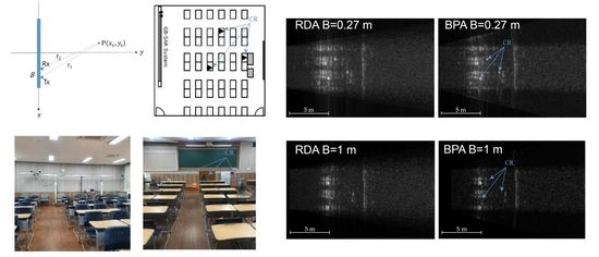
A bistatic GB-SAR system was constructed inside a common lecture room, 8 m wide and 10 m long, with multiple desks, chairs and three trihedral corner reflectors (CR) as shown in
Figure 1. A vector network analyzer (VNA, Anritsu MS2028B) was used to transmit and receive the microwave signal. Tx and Rx antennas were physically separated by a baseline
B for the bistatic GB-SAR configuration. Two square horn antennas in Ku-band were mounted on top of a platform running the rail system. The position and velocity of the platform were controlled by a stepping motor and a gear system connected to a conveyor belt. The motion of the platform was calibrated after the tension of the belt was adjusted. The whole system was controlled by a notebook computer with an in-house data acquisition software.
The center frequency used for this experiment was 15.95 GHz. The bandwidth was 1.6 GHz so that the range resolution was 9.4 cm nominally. VV polarization (vertically polarized wave both in Tx and Rx) is used to avoid mutual coupling between antennas aligned horizontally [
8]. The operable maximum length of the rail system is 6 m. The azimuth stepping distance was set to 3 cm so that the number of azimuth pulses was 201. The azimuth resolution of the real-aperture radar (RAR) would be 11.97° with 9 cm aperture length of the antenna, while that of SAR in strip-map mode would be a half of the real aperture, i.e., 4.5 cm for a conventional monostatic GB-SAR configuration [
10].
Table 1 shows the system parameters and variables used for the experiment.
2.2. Bistatic GB-SAR Focusing Algorithms
2.2.1. Range Compression
For a single radar acquisition, microwave signal is transmitted to the target and the returning signal is received while the antennas are in a stationary position at a certain location on a rail. VNA operates in a stepped-frequency sweep mode so that the returned signal is obtained as a function of frequency
f,
where
is a box function with a center frequency of
and a bandwidth of
.
is the scattering coefficient of a target as a function of frequency. Inverse Fourier transform of (1) results in the range-compressed signal as follows.
which is represented as a convolution (
) of an impulse response
and a scattering coefficient of targets
. In case of a point target where
,
is a sinc function with range time resolution
, and equivalently, range resolution
. This comprises a conventional monostatic radar [
10].
For a bistatic case with a baseline of
B, the iso-range planes are ellipsoids with two focal points at the antennae locations. In a range–azimuth plane in
Figure 1a, bistatic range (
) is the semi-minor axis of an iso-range ellipse where monostatic range
r is the semi-major axis. The range resolution of such bistatic radar can be defined by the derivative of bistatic range as follows.
The bistatic range resolution is always poorer than that of monostatic case [
14], and converges to the monostatic case if
or at far range where
B/r becomes negligibly small, as shown in
Figure 2. Note that this degraded range resolution effect of the bistatic configuration occurs at the very near range only and becomes less than 103% of a monostatic case at a range of
R = 2 m with
m. This effect would be negligible for airborne and satellite SAR operations when
B/r is relatively small.
2.2.2. Back-Projection Algorithm
For a point target
in
Figure 1a, the received signal at a given center position
between the two antennas separated by the baseline
is
where
Here,
is the coherent integration length in azimuth direction, which is a function of range
r,
The coherent integration length is less than the rail scan length, i.e., = 6 m, in this experiment.
The back-projection algorithm (BPA) is performed by a convolution of the received signal and a reference function so that the focused signal is obtained by
where
, the conjugate of (4). Analytical evaluation of (7) results in a sinc function [
10] that defines the azimuth resolution. For a bistatic GB-SAR system, the azimuth resolution if further restricted to the overlapping portion of the Tx and Rx antenna footprints by
For a monostatic case (), the azimuth resolution of strip-map mode has a maximum value of , i.e., a half of the azimuth real aperture. However, the resolution becomes poorer for a bistatic GB-SAR configuration with increasing B, due to the reduced overlap of the Tx and Rx footprints. A squint operation of Tx and Rx for better overlap of the footprints would be preferable to enhance the azimuth resolution.
2.2.3. Range-Doppler Algorithm
BPA is accurate in geometry but time-consuming due to the computational burden of the time-domain convolution. Therefore, frequency-based focusing algorithms have been developed to reduce the processing time at the cost of image quality. The range-Doppler algorithm (RDA) is one of the widely used algorithms for many satellite and airborne SAR missions.
Formulation of RDA for the bistatic GB-SAR begins with a Taylor series expansion of the phase at
so that
where
and
are Doppler centroid and Doppler rate, respectively, defined by
and
.
Azimuth compression for RDA begins with the Fourier transform of the received signal to the Doppler (wavenumber)
domain by:
Stationary phase occurs when the derivative of the phase of the integrand in (10) is zero, so that
This is the locking relationship between the rail position in space and the wavenumber Doppler, enabling range migration in wavenumber domain. Note that (11) was acquired by cancelling the terms higher than the quadrature.
After range migration, azimuth compression is performed as follows.
after which the focused signal
is obtained by the inverse Fourier transformation of the above signal.
We need to evaluate the Doppler centroid and Doppler rate for the bistatic GB-SAR. Doppler is a wavenumber defined by the change of phase with respect to
.
Doppler centroid is then
, i.e., the Doppler centroid of the bistatic GB-SAR is zero, the same with the monostatic case in [
10].
The derivative of Doppler is as follows.
Doppler rate is then defined by
If
,
, which is the same with the monostatic case in [
10].
Figure 3 shows Doppler rate versus range with various
B values. The value deviates from the monostatic case (
B = 0) especially at near range, which means the cancellation of the higher term in (11) would be inappropriate and causes image degradation at the near range for RDA. However, the bistatic Doppler rate approaches 97% of the monostatic case at
r = 4 m and the image degradation becomes negligible at far range. This effect can be seen in the experimental results in the next section.
3. Results
Figure 4 shows radar images after range compression (before azimuth compression) with varying baselines
B. Parabolic signals returned from three corner reflectors are clearly seen when
B is small (0.27 m) while reduced at larger
B (0.5 m and 1 m) due to the strong uni-directional backscattering characteristics of the trihedral corner reflectors (CR). Coherent integration length (
X) is also reduced accordingly with increasing
B as described in Equation (6). The power of the returned signal was also reduced due to the non-squint setup of this experiment, i.e., the footprint of Tx and Rx did not match completely with each other. This is partly intended to simulate the satellite bistatic configuration with no designated target area or squint mode.
Figure 5 is the comparison of SAR-focused images generated by (a) RDA and (b) BPA when
B = 0.27 m. Rows of classroom chairs and desks, a teacher’s computing desk and a blackboard hung on the wall have been successfully imaged. Three corner reflectors on top of desks were also clearly shown. Image degradation occurs at near range (less than 4 m) of RDA due to the approximation used for this frequency-domain focusing algorithm, as described in the previous section.
Figure 6 and
Figure 7 also show the same images with increasing
B. Image degradation at the near range worsened with increasing
B, and the power and azimuth resolution were also reduced due to the reduced coherent integration length. Signals from the three CRs were lost completely when
B = 1 m (
Figure 7) as expected, while those from other objects such as chairs, desks, and blackboard, still remained strong due to their bi-directional scattering property.
4. Discussion
The bistatic GB-SAR configuration is beneficial for the study of bi-directional scattering properties of targets, which provides better performance in target identification and classification. However, the image quality of a bistatic GB-SAR configuration would be less than that in the monostatic one due to the following four major reasons.
Firstly, the degradation of range resolution at an extremely near range occurs due to the inherent bistatic geometry as shown in Equation (3). However, this effect would be negligible for most of the usable range for airborne, satellite, or GB-SAR operations where B/r is negligible.
Secondly, the reduction in coherent integration length and thus azimuth resolution occurs with increasing baseline
B, as shown in Equation (8) and in
Figure 5,
Figure 6 and
Figure 7. One can use squint operation of Tx and Rx so that antenna footprints overlaps completely with each other.
Thirdly, the returned power would be reduced especially for strong uni-directional backscattering targets such as trihedral corner reflectors. Most natural targets are bi-directional scatterers, and such bistatic operation will be advantageous to assess the scattering property of natural targets. Manufactured targets may have well-known scattering properties and such bistatic SAR configurations would be helpful for target identification and reconnaissance purposes.
Lastly, a complex geometry of bistatic configuration may be a hurdle for the use of approximation in the frequency-domain SAR focusing algorithms as shown in Equation (16). More sophisticated SAR focusing algorithms should be developed for bistatic SAR operations onboard airborne or satellite configurations for faster SAR processing. In any case, BPA, which is slow but accurate, would be a good reference for the evaluation of the other frequency-domain focusing algorithms.
In this experiment, we used a Ku-band system to achieve high resolution in a conventional lecture room—a large bandwidth with small antenna aperture. The results show that such an experiment can be done cost-effectively with no high-end facilities such as an anechoic chamber.
The purpose of this experiment was to simulate the case of a satellite mission where Tx is followed by an Rx (or vice versa) with no specific target distance or squint operation. Although the indoor experimental setup allows relatively small B/r of 0.5~0.01, it can detect the bi-directional scattering effect of targets. This is just one case study of many bistatic SAR configurations. The GB-SAR system is versatile to use various frequencies and bandwidths as far as the antenna characteristics are supported. Other bistatic modes can also be applicable such as the bistatic SAR with larger B/r, one with squint operation, one-stationary-and-one-moving antenna mode, and one with arbitrary antenna positions. The system can also be extendable to multistatic modes by adding microwave switches. More sophisticated bistatic cases will be reported separately in the near future.
5. Conclusions
We have constructed a conventional linear-scanning GB-SAR system in the Ku-band and operated in bistatic mode where Rx follows Tx separated by several different baselines. A back-projection algorithm and range-Doppler algorithm were developed for the bistatic GB-SAR focusing.
The results showed that the targets were images at a designed quality and resolution. The characteristic effects of bistatic configurations were identified such as the reduction in azimuth resolution and power due to the reduced coherent integration length and the uni-directional backscattering properties of CR. The use of squint mode and the necessity of more robust frequency-domain algorithms were suggested for the satellite or airborne bistatic SAR configurations.
The advantages of bistatic SAR configurations would be numerous such as the investigation of the bi-directional scattering target properties and the systematic versatility for SAR constellation operation, which would lead to the rapid development of bistatic satellite SAR techniques in the near future.
Author Contributions
Conceptualization, H.L. and J.M.; methodology, H.L.; software, H.L.; validation, J.M.; formal analysis, H.L. and J.M.; investigation, H.L. and J.M.; resources, J.M.; data curation, J.M.; writing—original draft preparation, H.L.; writing—review and editing, H.L.; visualization, H.L. and J.M.; supervision, H.L.; project administration, H.L.; funding acquisition, H.L. All authors have read and agreed to the published version of the manuscript.
Funding
This research was supported by the Next Generation SAR Laboratory funded by Defense Acquisition Program Administration (DAPA) and Agency for Defense Development (ADD).
Institutional Review Board Statement
Not applicable.
Informed Consent Statement
Not applicable.
Data Availability Statement
The data presented in this study are available on request from the corresponding author.
Conflicts of Interest
The authors declare no conflict of interest.
References
- Krieger, G.; Moreira, A. Spaceborne bi- and multistatic SAR: Potential and challenges. IEEE Proc. Radar Sonar Navig. 2006, 153, 184–198. [Google Scholar] [CrossRef]
- Rabus, B.; Eineder, M.; Roth, A.; Bamler, R. The shuttle radar topography mission—A new class of digital elevation models acquired by spaceborne radar. ISPRS J. Photogramm. Eng. Remote Sens. 2003, 57, 241–262. [Google Scholar] [CrossRef]
- Krieger, G.; Moreira, A.; Fiedler, H.; Hajnsek, I.; Werner, M.; Younis, M.; Zink, M. TanDEM-X: A satellite formation for high-resolution SAR interferometry. IEEE Trans. Geosci. Remote Sens. 2007, 45, 3317–3341. [Google Scholar] [CrossRef]
- Romeiser, R.; Runge, H. Theoretical evaluation of several possible along-track InSAR modes of TerraSAR-X for ocean current measurements. IEEE Trans. Geosci. Remote Sens. 2007, 45, 21–35. [Google Scholar] [CrossRef]
- Nies, H.; Loffeld, O.; Natroshvili, K. Analysis and focusing of bistatic SAR data. IEEE Trans. Geosci. Remote Sens. 2007, 45, 3342–3349. [Google Scholar] [CrossRef]
- Wang, R.; Loffeld, O.; Neo, Y.L.; Nies, H.; Dai, Z. Extending Loffeld’s bistatic formula for the general bistatic SAR configuration. IET Radar Sonar Navig. 2010, 4, 74–84. [Google Scholar] [CrossRef]
- Bárcena-Humanes, J.L.; Gómez-Hoyo, P.J.; Jarabo-Amores, M.P.; Mata-Moya, D.; Del-Rey-Maestre, N. Feasibility study of EO SARs as opportunity illuminators in passive radars: PAZ-based case study. Sensors 2015, 15, 29079–29106. [Google Scholar] [CrossRef] [PubMed]
- Lee, H.; Ji, Y.; Han, H. Experiments on a Ground-Based Tomographic Synthetic Aperture Radar. Remote Sens. 2016, 8, 667. [Google Scholar] [CrossRef]
- Lee, H.; Cho, S.J.; Sung, N.H.; Kim, J.H. Development of a GB-SAR system (I): System configuration and interferometry. Korean J. Remote Sens. 2007, 23, 237–245. [Google Scholar]
- Lee, H.; Cho, S.J.; Sung, N.H.; Kim, J.H. Development of a GB-SAR (II): Focusing algorithms. Korean J. Remote Sens. 2007, 23, 247–256. [Google Scholar]
- Lee, H.; Lee, J.-H.; Kim, K.-E.; Sung, N.-H.; Cho, S.-J. Development of a Truck-Mounted Arc-Scanning Synthetic Aperture Radar. IEEE Trans. Geosci. Remote Sens. 2014, 52, 2773–2779. [Google Scholar] [CrossRef]
- Krysik, P.; Maslikowski, L.; Samczynski, P.; Kurowska, A. Bistatic ground-based passive SAR imaging using TerraSAR-X as an illuminator of opportunity. In Proceedings of the 2013 International Conference on Radar (Radar), Adelaide, SA, USA, 9–12 September 2013; pp. 39–42. [Google Scholar]
- Feng, W.; Friedt, J.; Nico, G.; Wang, S.; Martin, G.; Sato, M. Passive Bistatic Ground-Based Synthetic Aperture Radar: Concept, System, and Experiment Results. Remote Sens. 2019, 11, 1753. [Google Scholar] [CrossRef]
- Lazarov, A.; Kostadinov, T. Analytical Geometrical Determination of BSAR Resolution. In Bistatic SAR/GISAR/FISAR Geometry, Signal Models and Imaging Algorithms; John Wiley & Sons, Inc.: Hoboken, NJ, USA, 2014; pp. 65–75. [Google Scholar]
| Publisher’s Note: MDPI stays neutral with regard to jurisdictional claims in published maps and institutional affiliations. |
© 2020 by the authors. Licensee MDPI, Basel, Switzerland. This article is an open access article distributed under the terms and conditions of the Creative Commons Attribution (CC BY) license (http://creativecommons.org/licenses/by/4.0/).


