Article

Estimation of GPS Differential Code Biases Based on Independent Reference Station and Recursive Filter

1
Shanghai Astronomical Observatory, Chinese Academy of Sciences, Shanghai 200030, China
2
School of Astronomy and Space Science, University of Chinese Academy of Sciences, Beijing 100049, China
3
School of Remote Sensing and Geomatics Engineering, Nanjing University of Information Science and Technology, Nanjing 210044, China
4
Jiangsu Engineering Center for Collaborative Navigation/Positioning and Smart Applications, Nanjing 210044, China
5
Institute of Solar-Terrestrial Physics, German Aerospace Center, Kalkhorstweg 53, 17235 Neustrelitz, Germany
*
Author to whom correspondence should be addressed.
Remote Sens. 2020, 12(6), 951; https://doi.org/10.3390/rs12060951
Submission received: 17 February 2020 / Revised: 9 March 2020 / Accepted: 13 March 2020 / Published: 16 March 2020
(This article belongs to the Special Issue Remote Sensing of Ionosphere Observation and Investigation)

Abstract

:
The differential code bias (DCB) of the Global Navigation Satellite Systems (GNSS) receiver should be precisely corrected when conducting ionospheric remote sensing and precise point positioning. The DCBs can usually be estimated by the ground GNSS network based on the parameterization of the global ionosphere together with the global ionospheric map (GIM). In order to reduce the spatial-temporal complexities, various algorithms based on GIM and local ionospheric modeling are conducted, but rely on station selection. In this paper, we present a recursive method to estimate the DCBs of Global Positioning System (GPS) satellites based on a recursive filter and independent reference station selection procedure. The satellite and receiver DCBs are estimated once per local day and aligned with the DCB product provided by the Center for Orbit Determination in Europe (CODE). From the statistical analysis with CODE DCB products, the results show that the accuracy of GPS satellite DCB estimates obtained by the recursive method can reach about 0.10 ns under solar quiet condition. The influence of stations with bad performances on DCB estimation can be reduced through the independent iterative reference selection. The accuracy of local ionospheric modeling based on recursive filter is less than 2 Total Electron Content Unit (TECU) in the monthly median sense. The performance of the recursive method is also evaluated under different solar conditions and the results show that the local ionospheric modeling is sensitive to solar conditions. Moreover, the recursive method has the potential to be implemented in the near real-time DCB estimation and GNSS data quality check.

Graphical Abstract

1. Introduction

Nowadays, Global Navigation Satellite Systems (GNSS) observations provide various ways to estimate geophysical parameters, and one of the most important parameters is the total electron content (TEC) measurements for Earth’s ionosphere research [1,2,3,4,5,6]. Due to the frequency dispersive property of the ionosphere, the ionospheric delay experienced by electromagnetic signals can be estimated by dual-frequency measurements. The relatively high-precision ionospheric TEC can be derived from dual frequency GNSS carrier phase leveling pseudorange measurements, in which the differential code bias (DCB) is one of the main errors that cannot be ignored for absolute TEC estimation.
Recently, a number of algorithms for GNSS DCB estimates based on multi-frequency measurements have been proposed [7,8,9]. Apart from the commonly adopted method by setting the DCB as a constant during the GNSS TEC estimation [10,11,12,13,14,15], some other algorithms are proposed to decrease the computation costs by utilizing global ionospheric maps [4]. Furthermore, various optimization methods have been proposed for faster DCB determination and more accurate ionospheric modeling, such as optimization on DCB estimation based on regional or single station ionospheric modeling [16,17,18,19,20,21,22,23,24,25,26,27,28,29]. Keshin [30] estimated the single receiver DCBs using the global ionospheric map (GIM) vertical TEC gridded values, based on least square techniques with a linear constraint. An algorithm called IGG algorithm based on generalized triangular series function and satellite filtering was developed and used to generate the DCB product from the Chinese Academy of Sciences [31]. Sarma et al. [32] proposed an algorithm based on singular value decomposition to estimate three receiver biases. Among all these methods, several fundamental assumptions are adopted. One of those assumptions is that all the electrons in the earth’s ionosphere are concentrated in one single thin layer. While these single-layer TEC models may adopt different ionospheric effective heights, ranging from 350 to 450 km according to the spatial and temporal variation of the electron maximum height of the F2 layer. Another assumption is that both satellite and receiver DCBs are constant during a single day. One more constraint to overcome the ill-posed problem of the design matrix is usually called zero-mean constraint, which is used as a Lagrange multiplier to separate the satellite and receiver DCBs into two parts. It is necessary to point out that the zero-mean condition can vary with respect to the observable satellites, which may lead to a drift in DCB estimates with respect to DCB products provided by some IGS analysis centers like Center for Orbit Determination in Europe (CODE). In addition, Hong et al. [33] proposed a new and efficient algorithm using the geometry conditions between satellite and tracking receivers to estimate the receiver DCBs with no use of the single layer assumption, but requiring to know one receiver DCB.
For single-station DCB estimates, there are two basic approaches. One category of research models is based on a polynomial of coordinates in the Earth–Sun reference system, including the satellite and receiver DCBs in the model. The polynomial coefficients and DCBs are regarded as unknown parameters to be solved, and the observations form a linear set of equations which can be solved in the least square sense [34,35,36,37,38,39,40]. The other category makes use of the assumption that VTECs computed from different satellites over a certain angle of elevation are close to each other [41,42]. Therefore, the receiver DCBs can be estimated by minimizing the standard deviation of VTEC. Both of these two methods can be used to estimate the receiver DCBs for one single station, as long as the satellite DCB can be provided by other sources, such as the global GNSS network.
The ionospheric conditions vary with many factors such as space weather, local time and solar activities, geographic location and so on, particularly in equatorial regions in modeling and computation of TEC [43]. In order to estimate precise DCBs and analyze the performance of each tracking station located at different regions on the local ionospheric model, in this paper we present a recursive method for both satellite and receiver DCB estimates, together with a reference station selection procedure. The influence of the reference station selection on DCB estimates is discussed through a comparison between using all stations and only reference stations. The accuracy of DCB estimates and local ionospheric models are evaluated by the CODE DCB product and GIM. In the following, methods and observations are presented in Section 2, results and analyses are shown in Section 3, some discussions are presented in Section 4 and finally conclusions are given in Section 5.

2. Methods and Observations

2.1. Carrier Phase Smoothing Pseudorange

The time delays of GNSS signals received by GNSS receivers are converted to pseudo-range values and the phase shifts are recorded as phase delays in the receivers [44]. The standard model for pseudo-range and phase recordings for dual frequencies f 1 and f 2 are as follows [43]:
P i , u m = p u m + c ( δ t u δ t m ) + d t r o p , u m + d i o n   i , u m + c ( D C B s + D C B r )
L i , u m = p u m + c ( δ t u δ t m ) + λ i φ t r o p , u m + λ i φ i o n   i , u m c ( D C B s + D C B r ) + λ i N i m
where the subscript u denotes the receiver, the superscript m denotes the satellite, the subscript i denotes the frequency, p is the actual range between satellite and receiver, δ t u and δ t m are the clock errors for the receiver and satellite, respectively, d t r o p , u m denotes the troposphere group delay, d i o n   i , u m denotes the ionospheric delay, c is the speed of light in vacuum and D C B s denotes the satellite differential code bias (DCB) and D C B r denotes the receiver DCB, λ i is the wavelength, φ t r o p , u m denotes the phase shift due to the troposphere, φ i o n   i , u m denotes the phase shift due to the ionosphere and N i m denotes the initial phase ambiguity.
The slant TEC (STEC) can be obtained by utilizing the geometry-free observations with ignoring the higher order effects of the ionosphere. A relatively accurate TEC value can be obtained by a carrier phase smoothing pseudorange method, which can be expressed as follows:
{ STEC = k ( L 1 L 2 N ¯ DCB r D C B s ) k = f 1 2 f 2 2 40.3 ( f 1 2 f 2 2 )
where L i is the carrier phase observation, N i is the carrier phase ambiguity, P i is the pseudorange observation, ε L and ε P are the noise and multi path errors in the carrier phase observation and pseudorange observation, respectively, f i is the frequency of L i , D C B r is the LEO receiver DCB, D C B s is the Global Positioning System (GPS) satellite DCB, and N ¯ is the average ambiguity.

2.2. Local Ionospheric Modeling

Instead of using the Global Ionospheric Map (GIM) as a reference ionosphere background or global ionospheric modeling, we establish a local ionospheric VTEC model centered at one single station based on a recursive filter to estimate the GPS satellite and ground receiver DCBs. The measurements of TEC plus DCB, which is denoted as relative STEC, can be expressed as follows.
S T E C r e l = S T E C + D C B r + D C B s + ε
where S T E C r e l represents the relative STEC, i.e., the combination of satellite and receiver DCB, S T E C represents the absolute STEC, and ε represents all possible errors.
Our local ionosphere model parameterizes the vertical TEC (VTEC) distribution by a single layer at height 450 km. The spatial-temporal variations of the VTEC near the ground GNSS receiver are parameterized by a 2-degree polynomial fitting.
V T E C ( u 1 , u 2 ) = a 0 + a 1 u 1 + a 2 u 2 + a 3 u 1 2 + a 4 u 2 2 + a 5 u 1 u 2
where the five model coefficients are a 0 , a 1 , a 2 , a 3 , a 4 and a 5 . The coordinates longitude u 1 and latitude u 2 are both evaluated at the corresponding ionospheric pierce point (IPP) in a local sun-fixed coordinate system, centered at the receiver position. The slant ionospheric delay is converted to the vertical ionospheric delay by an elevation-dependent mapping function MF.
{ S T E C = V T E C · M F M F = [ c o s ( arcsin ( R e · c o s θ R ) ] 1 R = R e R e + H i o n
where V T E C represents the vertical TEC at the ionospheric pierce point (IPP), M F represents the mapping function, θ represents the elevation angle, R e represents the mean radius of the Earth and H i o n represents the single layer height, i.e., 450 km.

2.3. Model Initialization and Propagation

In order to maximize the reliability of the local VTEC model, we minimize the cost function at the initial state, with the observations occurring from 0000 LT to 0400 LT, due to the fact that the nighttime ionosphere is less variant than the daytime ionosphere.
The cost function is given by
{ J 0 = 1 2 ( y A 0 X 0 ) T C 0 1 ( y A 0 X 0 ) C 0 = d i a g [ σ r e l T E C 2 / ( 1 + c o s 2 θ ) ] X n = [ x n ; d n ] A n = [ A n x , A n d ]
where x n represents the local ionospheric model parameters, d n represents the combination of satellite and receiver DCBs, called as combination for brevity later, A n represents a design matrix which is divide into two parts A n x and A n d , y represents the relative STEC, C 0 represents the initial covariance matrix, θ represents the elevation angle and σ r e l T E C represents the standard deviation of the relative STEC provided by the pre-processing procedure. Subscript “n” represents the parameter evaluated at step n when n is larger than 0. Note that the observable GNSS satellites between two adjacent steps are not necessarily the same. The elevation mask is set to 20 degrees to reduce the multipath effects and mapping errors. At the initial step, observations, of which the longitude differences between the corresponding IPP and model origin (0200 LT) are more than 30 degrees (2 h), are discarded.
After initializing the local ionospheric model, we proceed to propagate the model into the next step, assuming that the only difference of local ionospheric models between two adjacent periods results from the second term in (5), i.e., u 1 . The propagation procedure when neglecting the second order contribution can be expressed as follows:
{ x n = U x n 1 U = ( 1 a 1 δ u 1 1 0 0 1 1 1 ) δ u 1 = δ t 12 · π
where x n represents the ionospheric model parameter vector before updating, x n 1 represents the ionospheric model parameters after updating at n 1 th step, U represents the model propagation matrix and δ t represents the time interval between n th step and n 1 th step, which is set to 900 s in this study.
In terms of covariance matrix determination, it is assumed here that the model updating error is independent of the model error, which allows us to determine the total covariance in the following step by
C n = C n M + C n 1 U
where C n represents the total covariance matrix, C n M represents the model covariance matrix and C n 1 U represents the model update covariance matrix.
According to the model propagation procedure (8), the model covariance matrix can be expressed simply as
C n M = U T C n 1 M U
where C n M represents the model covariance matrix at n th step and C n 1 M represents the model covariance matrix at n 1 th step.
Furthermore, the model updating uncertainty is attributed mainly to the asymmetric term in the model propagation matrix U, i.e., a 1 δ u 1 , due to the fact that the model propagated from the previous step may not be the optimal local ionospheric model in the current step. Thus, we assume that the model updating matrix is proportional to a 1 n 2 . The model updating covariance matrix can be written as follows:
C n U = a 1 n 2 a 1 ( n 1 ) 2 ( C n C n p o s t e r i o r )
{ C n p o s t e r i o r = σ n 2 · ( A n x T P A n x ) 1 C n = ( σ n ) 2 · ( A n x T P A n x ) 1
{ σ n 2 = ( A n x x ^ n Y n ) T P ( A n x x ^ n Y n ) N 1 ( σ n ) 2 = ( A n x x n Y n ) T P ( A n x x n Y n ) N 1
Y n = y n A n d d n
where a 1 n represents the model coefficient a 1 in step n, C n U represents the model updating covariance matrix,   C n p o s t e r i o r represents the posterior covariance matrix after updating the model, C n represents the posterior covariance matrix before updating the model, P represents the weight matrix determined by the inverse matrix of C 0 in (7), x ^ n represents the model parameter vector after updating, N represents the number of all available observations, y n represents the relative STEC in step n and Y n represents the absolute STEC vector calculated from the ground observations. Note that in (12) and (13), we assume that all DCBs are constant or much less variant than ionospheric VTEC during every consecutive observation series, so that the variance evaluated in (12) is exactly the ionospheric model variance.

2.4. Recursive Filter

Considering the contribution of the local ionospheric model, the extended cost function can be expressed as
J n = 1 2 [ ( y n A n X n ) T P 1 ( y n A n X n ) + ( x n x n ) T C n 1 ( x n x n ) ]
To avoid any negative values of a 0 , which violates fundamental physics, we here employ an inequality constrained least square (ICLS) technique on the minimization process (15) [45]. Furthermore, the model propagation always continues in the same way, while we discard the DCB combinations derived from those observations, in which the first model parameter a 0 is smaller than 0 total electron content unit (TECU), which implies possibly poor qualities among them.
After deriving the DCB combinations, equations containing satellite and receiver DCBs can be written in the form as (16).
{ D · X + ε r = Z X = [ D C B r T ,   ( D C B s ) T ] T
where D is the design matrix, the elements corresponding to the satellite and receiver between which the observation happens are 1 and 0 for others, ε r is the residual, and Z is the combination vector of satellite and receiver DCBs estimated above. The satellite and receiver DCBs can be separated by imposing a zero-mean constraint on all the satellite DCBs, which can be expressed as:
{ S · X = 0 S = [ 0 0 n 1 , 1 1 ] n 2 X ^ = ( D T G D + S T S ) 1 D T G Z G = d i a g ( σ c o m 2 ) σ = s q r t [ ( Z D · X ^ ) T G ( Z D · X ^ ) N 0 ( n 1 + n 2 1 ) ]
where   S is the zero-mean constraint matrix, the elements corresponding to the satellite DCBs are 1 and 0 for others, X ^ is the optimal solution for satellite and receiver DCBs, G is the weight matrix for the combination, σ c o m is the standard deviation vector for the combination evaluated separately in every consecutive observation series, N 0 is the total number of the DCB combinations and σ is the weighted residual. See the flowchart of the recursive method in Figure 1 for more illustrations.

2.5. Reference Station Selection

Many previous researches suggested that data provided by mid-latitude stations are more reliable and recommended to be used than those provided by low-latitude stations. Since the quality of data recorded by the IGS stations are not evaluated in pre-processing, it is necessary to discard some stations with worse performances compared with other stations in order to ensure the accuracy of ionospheric modeling, as well as the DCB estimates. An automatically iterative process is employed to select the reference stations, which can be divided into three steps as following:
  • Estimating the satellite and receiver DCBs based on the recursive method described above with all observations.
  • Estimating only the receiver DCBs with the initial satellite DCB estimates in the first step, by using the same recursive method. Note that the receiver DCBs in this step are determined by the median value of all the 15-min estimates, because in this step there is no ill-posed problem like in step 1.
  • Comparing the receiver DCBs in the first and second step. If the difference between two receiver DCBs exceeds a threshold, we remove the corresponding station out of the set of reference stations and go back to step 1, until no station is removed in step 3. Then extract the final DCB estimates in this step. The threshold can be determined by the value of σ in the last formula in (17).

3. Results and Analyses

3.1. Experimental Data

In order to test the feasibility of the recursive filter method and reference station selection procedure, two experimental cases are designed. In each case, the GPS data are gathered from 130 IGS stations covering the whole globe (25 in low latitude region; 85 stations in mid latitude region; 20 stations in high latitude) from 15th to 31th January 2011. To avoid any extra uncertainties from a variable number of stations, we select those stations which provided continuous observations during the period of interests. In the first case, all stations play the equivalent role in in the DCB estimates. In the second case, however, those stations, which may lead to instabilities of DCB estimates or inaccuracies of ionospheric modeling, are discarded from the set of reference stations according to the criterion in step 3 mentioned above. The comparisons of DCB estimates between case 1 and 2 show the influence of the station selection on the performance of the recursive method. Moreover, the weight of each observation is evaluated as the second expression in (5). According to the daily DCB estimation of the recursive method described in Section 2, the combination of satellite and receiver DCBs is estimated in each time interval first and then the satellite and receiver DCBs are separated based on the zero-mean condition. It is noted that the discarded receiver’s DCBs are considered as the results in the last estimation round, in which this receiver is not discarded by then. As is mentioned in Section 2.3, local ionospheric modeling is based on the observations occurring between 0000 LT and 0400 LT, in order to minimize the initialization error once per local day. Data in two consecutive days in universal time are needed and gathered together as a whole observation in one local day, station by station. However, the CODE receiver DCBs are estimated once per day in universal time rather than in local time. Thus, we have to align our receiver DCB results to CODE DCB by linear interpolation.
{ D C B n ¯ = l o n 2 π D C B n + 1 + ( 1 l o n 2 π ) D C B n               l o n 0 D C B n ¯ = l o n 2 π D C B n 1 + ( 1 + l o n 2 π ) D C B n         l o n < 0
where D C B n ¯ is the aligned DCB estimate of day n in the universal time, l o n is the longitude of the station in rad,   D C B n 1 , D C B n and D C B n + 1 are the original DCB estimate of day n 1 , n and n + 1 in the local time, respectively. Note that l o n ranges from π to π corresponding to 180° W and 180° E.
It is also necessary to note that the satellite DCBs here do not need to be aligned due to the fact that satellite DCBs are very stable during consecutive days without hardware operations. Considering the shift between the universal time and local time in each station, the results in the last day, i.e., 31st January, are not shown below in the final estimates.

3.2. Evaluation of Local Ionospheric TEC Modeling

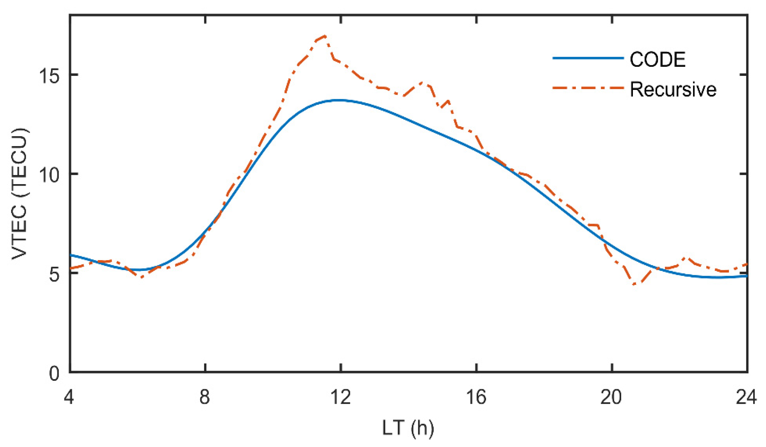
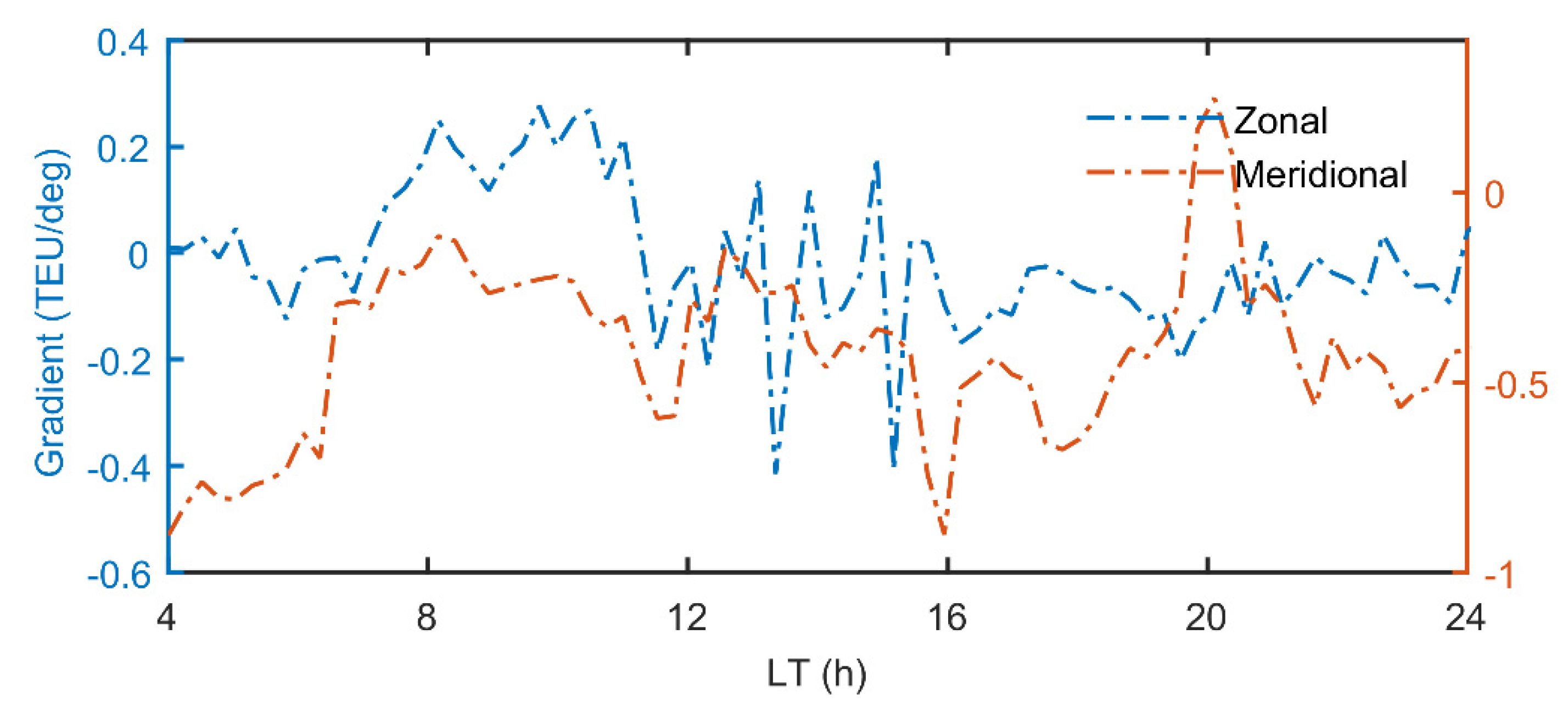
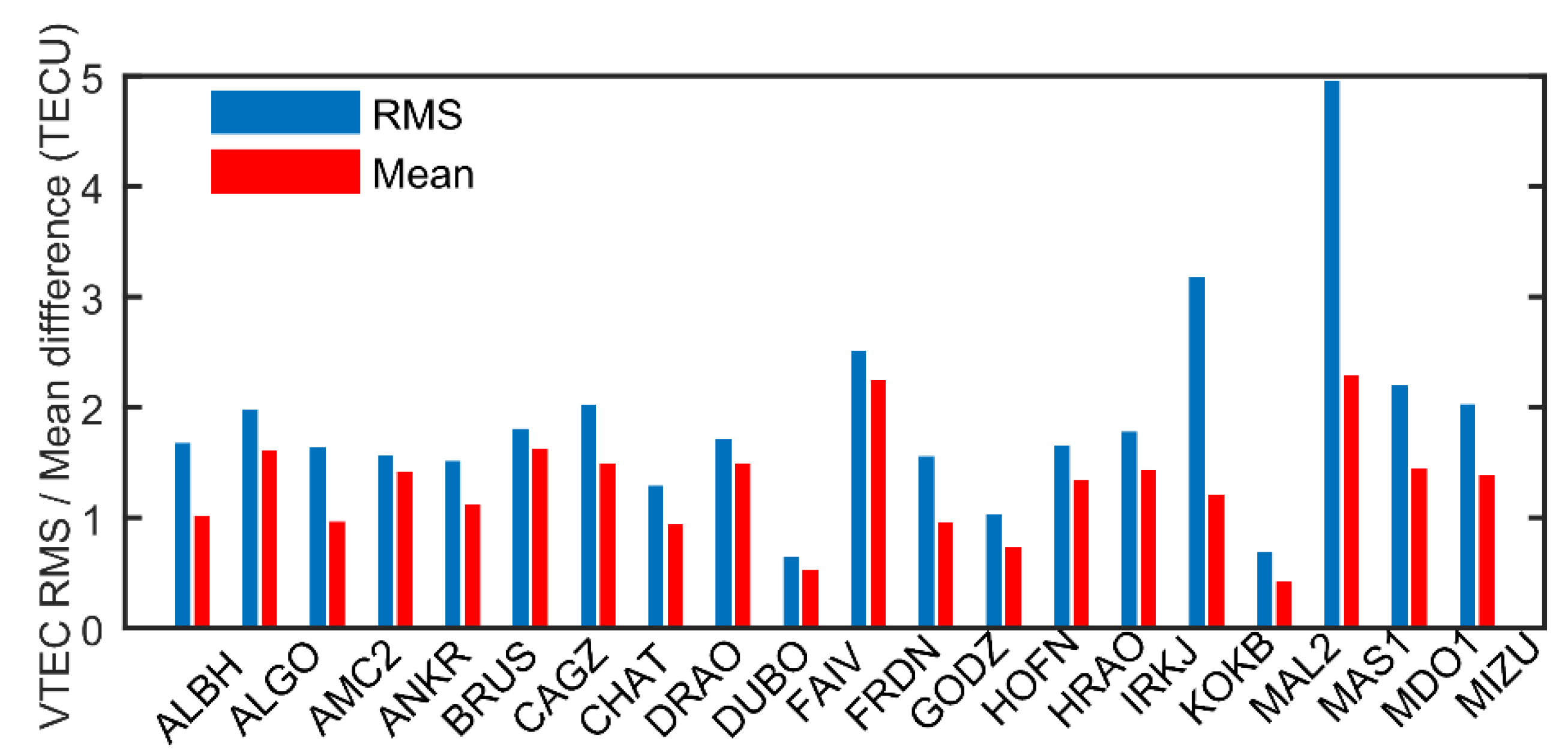
Figure 2 shows the comparisons between the VTEC derived from the recursive method and interpolation using CODE GIM. The VTEC derived from the recursive method is generally consistent with that of CODE GIM. However, considering that the interpolation could result in considerable errors and the spatial-temporal resolution of GIM is worse than the that of single-station VTEC, there could possibly exist a discrepancy between GIM and recursive VTEC. Figure 3 shows the second and third parameters representing zonal (blue line) and meridional (red line) gradients of VTEC over GODZ station. We can see from Figure 3 that the sign of meridional gradients shows an obvious hemispheric difference. For the GODZ station, which is located at the northern hemisphere, the meridional gradients stay negative over the course of the day. This can be expected, since the VTEC over equatorial regions are higher than those over higher latitudinal regions. For zonal gradients, the results show diurnal variations, which means that the zonal gradient increases in the first half of the day (or more precisely before 1400 LT) and then decreases in the second half of the day, considering the ionization peak at around 1400 LT. Figure 4 shows the semi-monthly mean difference and average RMS, with respect to interpolated CODE GIM over 20 sample stations. Among the twenty select stations, the largest RMS and mean difference both exist on MAS1 station with the value of 4.95 TECU and 2.28 TECU, respectively. The smallest RMS and mean difference both exist at MAL2 station, with the value of 0.69 TECU and 0.42 TECU, respectively. The median value of RMS is 1.69 TECU, while the median value of mean difference is 1.36 TECU.

3.3. Reference Station Selection

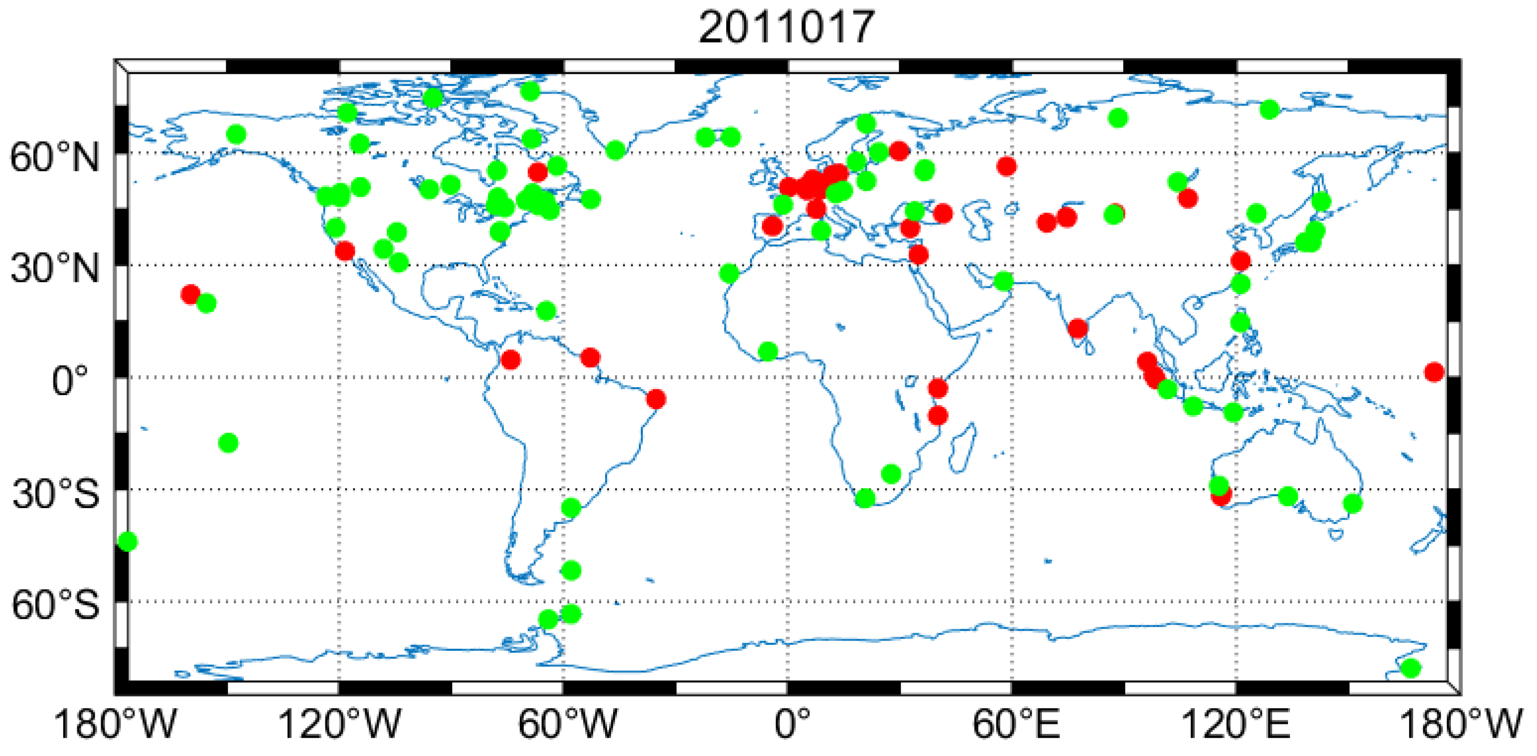
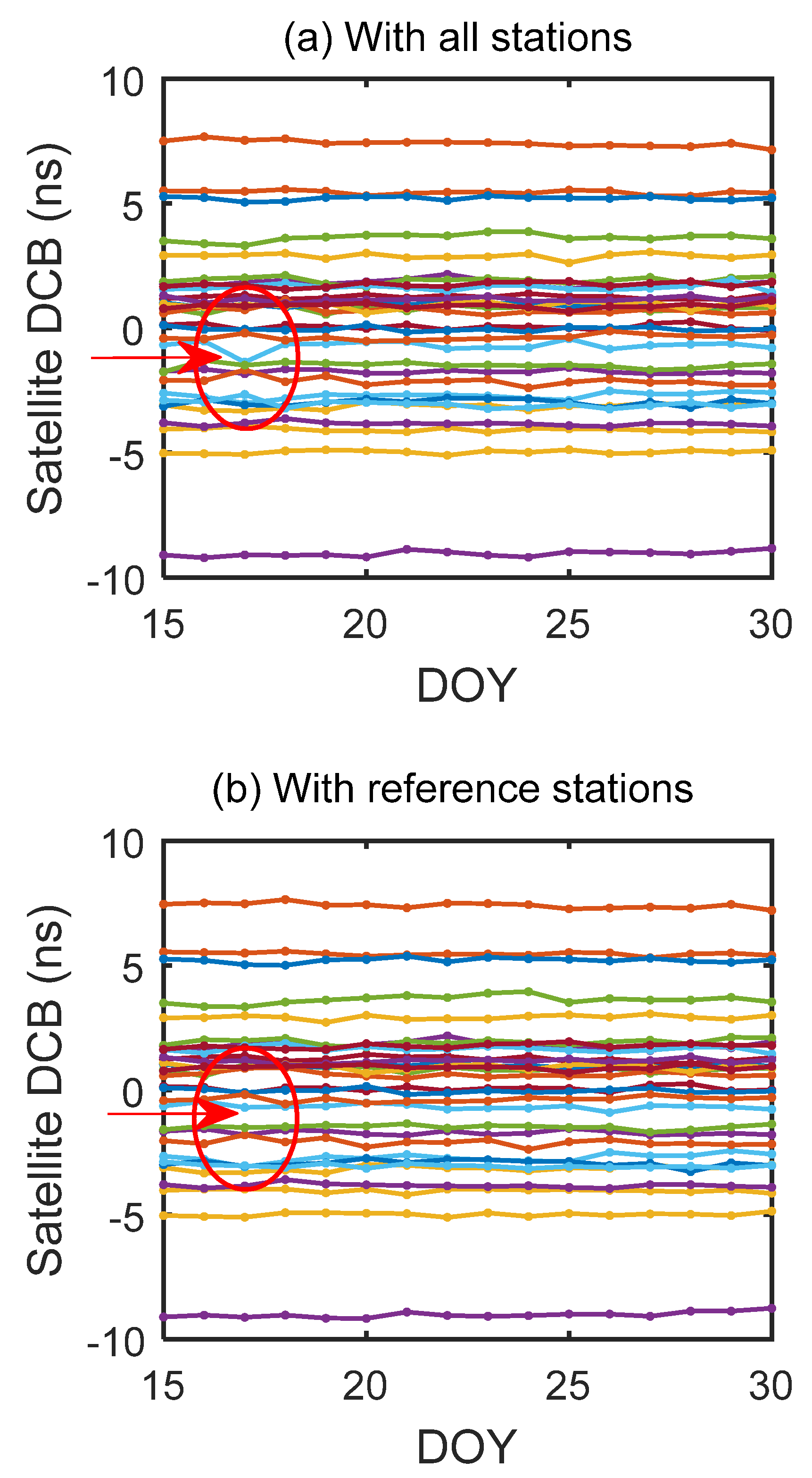
As mentioned earlier, some stations which performed worse than the other stations during the periods of interest can be removed from the filter. Since more mid-latitude stations are removed from the set of reference stations compared with other days, we choose to show the abandoned stations on 17th January as the red dots in Figure 5. In order to analyze the spatial distribution of discarded stations, we divide one hemisphere into three parts, i.e., low (0–30 degrees), mid (30–60 degrees) and high latitude (60–90 degrees). Table 1 shows the variations of the latitudinal distributions of discarded stations during the period of interests. From Table 1 we can see that the discarded stations are mostly located at low and mid latitude region, which is expected, because the number of stations located at mid latitude is much larger than those located at low and high latitude and previous work has shown that the stations in low latitudes are generally not as good as those in mid latitudes [31]. However, it can be found that the number of discarded stations located at low latitude is much larger than the number of discarded stations located at mid latitude, even though there are only five more stations located in mid latitude. It can be concluded that stations located in the low latitude region generally performed worse than those located in the mid and high latitude region. Figure 6 shows the time series of GPS satellite DCBs estimated by the recursive method before (a) and after (b) selecting reference stations during the period of interests. In the red ellipsoid of Figure 6a, an apparent jump in satellite DCB of PRN 20 occurred in 17th January. After selecting reference stations, the negative influence from those bad stations can be mitigated according to the recovery of the jump. The reason is the sudden increase of the number of discarded stations in the mid latitude region on 17th January. In order to illustrate more explicitly the variation of distribution of discarded stations, we present the successive daily changes of geographic distribution of the reference stations (shown in green dot) and discarded stations (shown in red dot), during 15th to 30th in January 2011 in the supplementary materials Figure S1.
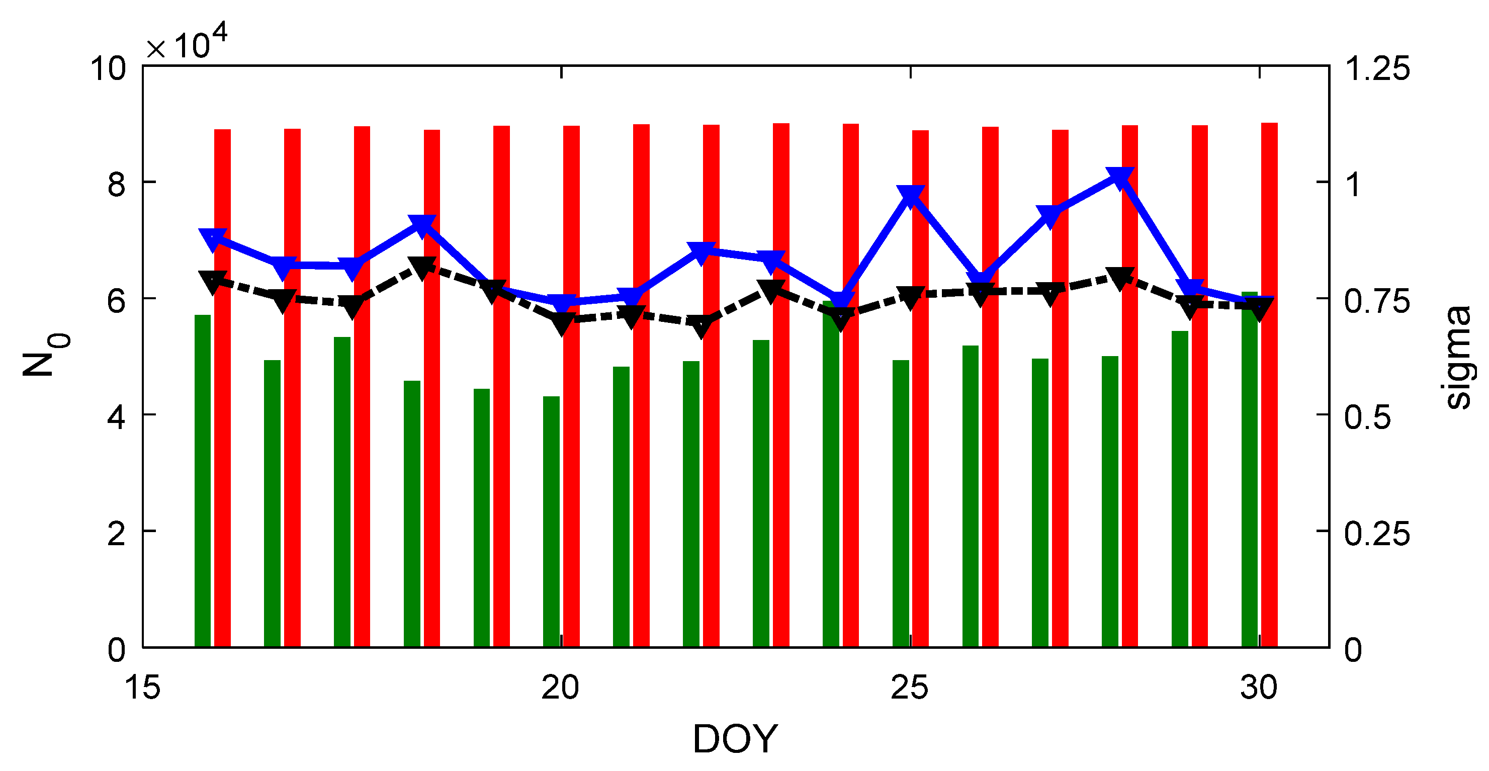
Figure 7 shows the number of total numbers of DCB combinations N 0 by bar plot in case 1 (red) and in case 2 (green), while the weighted residual σ in Eq. (17) is presented by line plot in case 1 (blue) and case 2 (black). We can see that the total number of DCB combinations in case 1 stays very invariant in the period of interest, whilst that in case 2 varies from day to day. Comparing the red and green bars, N 0 decreases by 40% in the mean sense in case 2. We have to note though, that on 17th January, N 0 is even larger than many other days; from Table 1 below, the number of discarded stations is largest during this period. This fact verifies that we correctly discarded those stations with only few and interrupted observations and kept the stably and continuously tracking stations in the set of reference stations. By comparing the blue and black lines, we can find that in most days except for 19th and 31st January, the weighted residual σ decreases in case 2, by a mean value of 0.10 ns. The comparison between two cases further confirms the feasibilities of the proposed reference selection procedure.

4. Discussion

4.1. Comparision with CODE DCB Product

In order to check the stabilities and accuracy of DCB estimates based on the recursive method, we introduce the day scatter and root mean square errors compared to CODE. The day scatter represents the day-to-day variation in daily DCB estimates, with respect to the monthly mean DCB estimates, as defined in (19) [45]. RMS is the root mean square errors with respect to CODE DCB product, which is expressed as (20).
DS = d = 1 D ( B d B ¯ ) 2 D 1
RMS = d = 1 D ( B d B C O D E d ) 2 D 1
where DS is the day scatter, D is the number of days of interests, B d is the satellite DCB estimates determined by recursive method, B ¯ is the mean value of the satellite DCB estimates, B C O D E d is the satellite DCB from CODE DCB product.
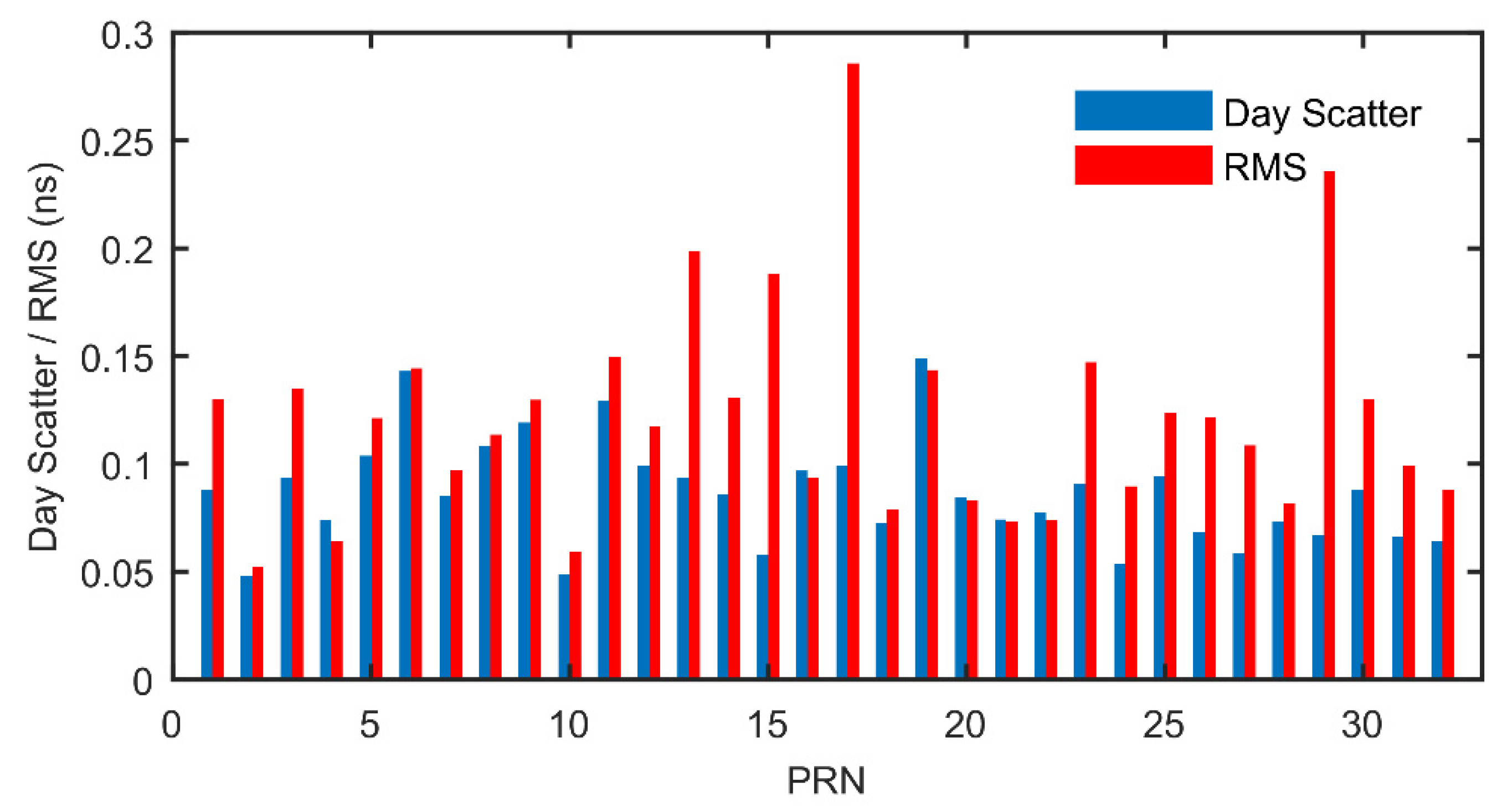
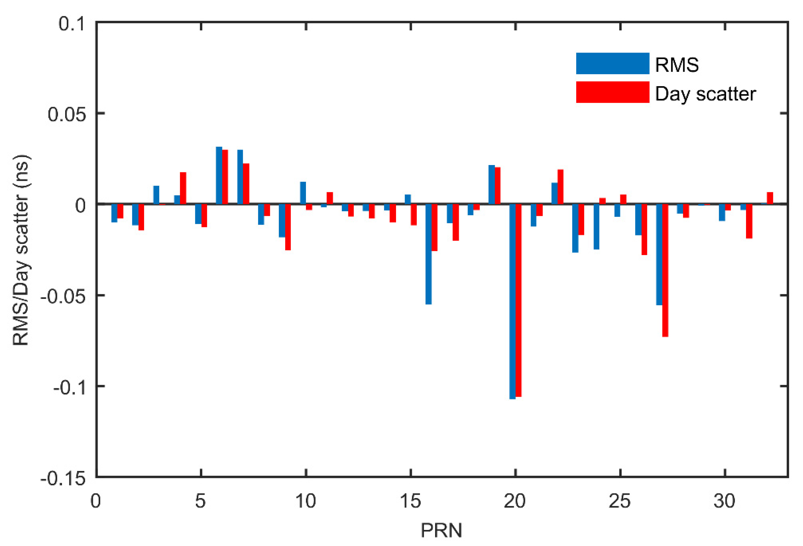
Figure 8 shows the day scatter of satellite DCB estimates determined by recursive method after selecting reference stations and corresponding RMS values with respect to CODE DCB during the periods of interest. The largest value of day scatter is 0.15 ns for PRN 19, while the lowest value is 0.05 ns for PRN 10; The largest value of RMS is 0.28 ns for PRN 17, while the lowest value is 0.05 ns for PRN 2. Figure 9 shows the difference of RMS and day scatter before and after selecting reference stations during the periods of interest. Comparing the results from two experimental cases, it can be seen that most of the satellite DCB estimates become more stable after selecting the reference stations, especially for PRN 20. The day scatter and RMS value for PRN 20 decreased by 0.10 ns and 0.11 ns, respectively. It can be suggested that the DCB stabilities of only the satellites that discarded stations may be able to track can be effectively improved. This is the reason why DCBs of satellites which cannot be tracked by the discarded stations do not change significantly after choosing the reference stations. For those satellites of which the day scatters increase, the increments of day scatters are all less than 0.03 ns, which is a slight increase compared with the decreases of some satellites, such as PRN 16, 20 and 27. Thus, we conclude that selecting reference stations are generally beneficial for the satellite DCB estimates.
For investigating the influence of reference station selection on the receiver DCB estimates, the comparisons of the differences between sample receiver DCBs with CODE receiver DCBs in the two cases mentioned above are presented in Table 2. From Table 2, we can see that most of the receiver DCBs, except for GODZ and QAQ1, become more stable in case 2 than in case 1, while the stabilities of receiver DCB determined by the recursive method are slightly worse than CODE DCB product, possibly because we use the observations with GPS satellites only. The monthly mean differences, with respect to CODE receiver DCB, decrease by 0.18, 0.23, 0.22, and 0.19 ns for HERS, IQAL, PERT and TIXI in case 2, while the other receiver DCBs remain at the same accuracy level. Considering the interactions among stations through the zero-mean condition, the reason may be attributed to that the discarded stations have little intersected satellites tracked by GODZ, QAQ1, REYK and YSSK. The influence of reference station selection on one station depends on the number of observations recorded, with the intersected satellites tracked by those discarded stations.

4.2. Dependence on Solar Condition

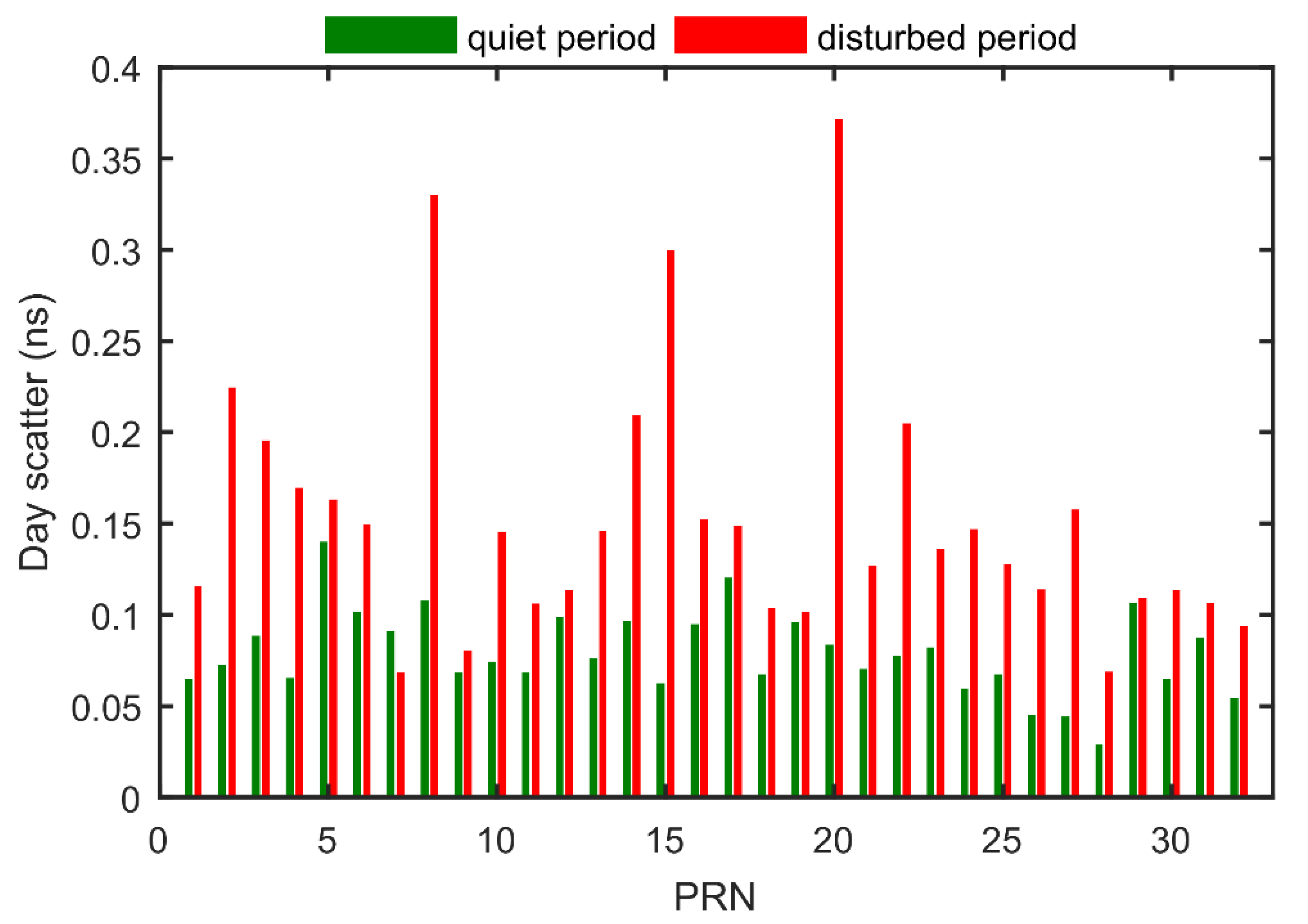
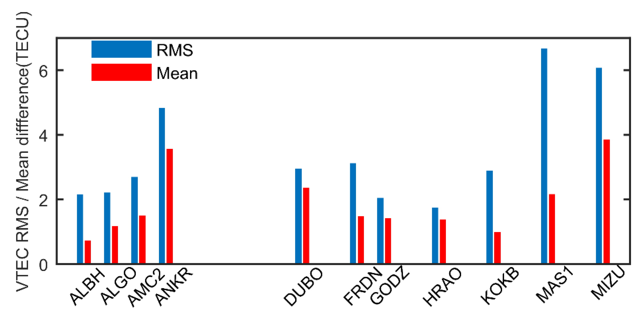
Considering that the ionosphere can be affected by solar activities severely, the performance of DCB estimates and ionospheric modeling can also degrade under disturbed solar conditions [46]. In order to evaluate the performance of recursive methods under different solar conditions, we carry out the same experiment described in Section 2 during 3rd to 12th in May 2015, when F10.7 index underwent an increase from 100 to 160 flux units, while F10.7 index kept a stable value of about 80 flux units during January 2011. Figure 10 shows the comparisons of satellite DCB stabilities between 21st to 30th in January 2011 and 3rd to 12th in May 2015. It can be seen from Figure 10 that the stabilities of satellite DCBs become worse during the solar disturbed period, which corresponds to May 2015, than those during the solar quiet period corresponding to January 2011, especially for PRN 8, 15 and 20 satellites, of which the day scatters are larger than 0.3 ns. Besides, the median value of day scatter increases from 0.08 ns during the solar quiet period to 0.15 ns during the solar disturbed period. There are two possible reasons for the degradation of accuracy, apart from the systematic errors including the mapping error and the ionospheric effective height determination error. One is the overall increase of ionospheric variabilities under stronger and disturbed solar condition, which leads to more errors in local ionospheric modeling and further affects the accuracy of DCB estimates. For example, during the solar disturbed period, the two-degree polynomial may not reproduce the horizontal structure of the local ionospheric VTEC so well as during the solar quiet period. The other reason may be the geographic distribution of the global stations selected. Because there are many more stations in the northern hemisphere, there could be an extra seasonal effect between May and January on the DCB estimates. Figure 11 shows the mean difference and RMS with respect to interpolated CODE GIM over 20 sample stations during the disturbed period. Since there were some stations which did not provide records during the disturbed period, we do not label the missed stations in Figure 11 but leave a blank space for the convenience of comparison with Figure 4. Comparing Figure 4 and Figure 11, it can be seen that the mean differences slightly increase during disturbed period, while RMS values increase significantly during the disturbed period, which means that the time series of local VTEC modeling are more fluctuated during the disturbed period than during the quiet period. This means that the performance of the recursive method is prone to the variabilities of the ionospheric TEC to some degree. Thus, we conclude that the performance of the recursive method can be affected by the solar condition, which is similar to other algorithms such as GIM. More studies are needed to reduce the possible error sources, especially during the disturbed period.

5. Conclusions

In this paper, we presented a recursive method to estimate satellite DCB and local ionospheric modeling, together with an independent reference station selection procedure. The implementation of the recursive method consists of three parts: first, the local ionospheric VTEC model and DCB of satellites and receivers are estimated based on a recursive filter; second, the receiver DCBs are estimated using the initial satellite DCB estimates from the first step based on the same recursive method; third, the stations which performed worse than the other stations are abandoned from the set of reference stations, according to the difference between two receiver DCB estimates and repeating the procedures above until no station is discarded in the third step. Based on the analyses with respect to the CODE product, the following conclusions are drawn: (1) The accuracy of satellite DCB estimates obtained by the recursive method can reach about 0.10 ns under solar quiet conditions; (2) the influence of stations with bad performances on DCB estimation can be reduced through the independent iterative reference station selection; (3) the accuracy of local ionospheric modeling based on recursive filter can reach less than 2 TECU in the monthly median sense under solar quiet conditions.
It is also necessary to note that the performance of the recursive method is sensitive to solar condition, and more works are needed to further mitigate the dependence of the recursive method on the solar condition. The overall increase of ionospheric variabilities under stronger and more disturbed solar conditions and asymmetry geographic distribution of the global stations selected can be responsible for the degradation of the performance. Considering the low cost and simplicity of implementation, the algorithm has potentials to be implemented in the near real-time DCB estimation and GNSS data quality check in the future [47].

Supplementary Materials

The following are available online at https://www.mdpi.com/2072-4292/12/6/951/s1, Figure S1: Successive daily changes of geographic distribution of reference stations (shown in green dot) and discarded stations (shown in red dot) during 15th to 30th in January 2011.

Author Contributions

Conceptualization, L.Y., M.H. and S.J.; methodology, L.Y. and M.H.; software, L.Y.; data curation, M.H.; writing—original draft preparation, L.Y.; writing—review and editing, S.J. and M.H.; supervision, S.J and M.H.; project administration, S.J and M.H..; funding acquisition, S.J and M.H. All authors have read and agree to the published version of the manuscript.

Funding

This research was funded by National Natural Science Foundation of China (NSFC) Project Grant Numbers 41761134092.

Acknowledgments

The authors would like to thank international GNSS service (IGS) for providing the global GNSS data and Center for Orbit Determination in Europe (CODE) for providing DCB products.

Conflicts of Interest

The authors declare no conflict of interest.

References

  1. Jin, S.; Jin, R.; Li, D. Assessment of BeiDou differential code bias variations from multi-GNSS network observations. Ann. Geophys. 2016, 34, 259–269. [Google Scholar] [CrossRef] [Green Version]
  2. Jin, S. Two-Mode Ionospheric Disturbances Following the 2005 Northern California Offshore Earthquake From GPS Measurements. J. Geophys. Res. Space Phys. 2018, 123, 8587–8598. [Google Scholar] [CrossRef]
  3. Klobuchar, J. Ionospheric Time-Delay Algorithm for Single-Frequency GPS Users. IEEE Trans. Aerosp. Electron. Syst. 1987, 325–331. [Google Scholar] [CrossRef]
  4. Su, K.; Jin, S.; Hoque, M.M. Evaluation of Ionospheric Delay Effects on Multi-GNSS Positioning Performance. Remote. Sens. 2019, 11, 171. [Google Scholar] [CrossRef] [Green Version]
  5. Jakowski, N.; Heise, S.; Wehrenpfennig, A.; Schlüter, S.; Reimer, R. GPS/GLONASS-based TEC measurements as a contributor for space weather forecast. J. Atmos. Solar Terr. Phys. 2002, 64, 729–735. [Google Scholar] [CrossRef]
  6. Jin, S.G.; Gao, C.; Li, J. Estimation and analysis of global gravity wave using GNSS radio occultation data from FY-3C meteorological satellite. J. Nanjing Univ. Infor. Sci. (Nat. Sci. Edn.) 2020, 12. [Google Scholar] [CrossRef]
  7. Wang, N.; Yuan, Y.; Li, Z.; Montenbruck, O.; Tan, B. Determination of differential code biases with multi-GNSS observations. J. Geod. 2016, 90, 209–228. [Google Scholar] [CrossRef]
  8. Hernández-Pajares, M.; Juan, J.M.; Sanz, J.; Orús, R.; García-Rigo, A.; Feltens, J.; Komjathy, A.; Schaer, S.C.; Krankowski, A.; Juan, J.M. The IGS VTEC maps: A reliable source of ionospheric information since 1998. J. Geod. 2009, 83, 263–275. [Google Scholar]
  9. Sakai, T.; Matsunaga, K.; Hoshinoo, K.; Walter, T. Modified ionospheric correction algorithm for the SBAS based on geometry monitor concept. In Proceedings of the 18th International Technical Meeting of the Satellite Division of The Institute of Navigation (ION GNSS 2005), Long Beach, CA, USA, 13–16 September 2005; pp. 735–747. [Google Scholar]
  10. Mannucci, A.J.; Wilson, B.D.; Yuan, D.N.; Ho, C.H.; Lindqwister, U.J.; Runge, T.F. A global mapping technique for GPS-derived ionospheric total electron content measurements. Radio Sci. 1998, 33, 565–582. [Google Scholar] [CrossRef]
  11. Schaer, S. Mapping and Predicting the Earth’s Ionosphere Using the Global Positioning System. Geod. Geophys. Arb. Schweiz 1999, 59. [Google Scholar]
  12. Jin, R.; Jin, S.; Feng, G. M_DCB: Matlab code for estimating GNSS satellite and receiver differential code biases. GPS Solut. 2012, 16, 541–548. [Google Scholar] [CrossRef]
  13. Ma, G.; Gao, W.; Li, J.; Chen, Y.; Shen, H. Estimation of GPS instrumental biases from small scale network. Adv. Space Res. 2014, 54, 871–882. [Google Scholar] [CrossRef]
  14. Ciraolo, L.; Azpilicueta, F.J.; Brunini, C.; Meza, A.; Radicella, S.M. Calibration errors on experimental slant total electron content (TEC) determined with GPS. J. Geod. 2007, 81, 111–120. [Google Scholar] [CrossRef]
  15. Hernández-Pajares, M.; Juan, J.M.; Sanz, J. New approaches in global ionospheric determination using ground GPS data. J. Atmos. Solar Terr. Phys. 1999, 61, 1237–1247. [Google Scholar]
  16. Wang, Q.; Jin, S.; Yuan, L.; Hu, Y.; Chen, J.; Guo, J. Estimation and Analysis of BDS-3 Differential Code Biases from MGEX Observations. Remote. Sens. 2020, 12, 68. [Google Scholar] [CrossRef] [Green Version]
  17. Rao, G.S. GPS satellite and receiver instrumental biases estimation using least squares method for accurate ionosphere modelling. J. Earth Syst. Sci. 2007, 116, 407–411. [Google Scholar]
  18. De Camargo, P.O.; Monico, J.F.G.; Ferreira, L.D.D. Application of ionospheric corrections in the equatorial region for L1 GPS users. Earth Planets Space 2000, 52, 1083–1089. [Google Scholar] [CrossRef] [Green Version]
  19. Zhou, P.; Wang, J.; Nie, Z.; Gao, Y. Estimation and representation of regional atmospheric corrections for augmenting real-time single-frequency PPP. GPS Solut. 2020, 24, 7. [Google Scholar] [CrossRef]
  20. Xiang, Y.; Gao, Y. Improving DCB Estimation Using Uncombined PPP. Navigation 2017, 64, 463–473. [Google Scholar] [CrossRef]
  21. Choi, B.-K.; Sohn, D.-H.; Lee, S.J. Correlation between Ionospheric TEC and the DCB Stability of GNSS Receivers from 2014 to 2016. Remote. Sens. 2019, 11, 2657. [Google Scholar] [CrossRef] [Green Version]
  22. Choi, B.-K.; Lee, S.J. The influence of grounding on GPS receiver differential code biases. Adv. Space Res. 2018, 62, 457–463. [Google Scholar] [CrossRef]
  23. Nie, W.; Xu, T.; Rovira-Garcia, A.; Juan, J.M.; Subirana, J.S.; González-Casado, G.; Chen, W.; Xu, G. Revisit the calibration errors on experimental slant total electron content (TEC) determined with GPS. GPS Solut. 2018, 22, 85. [Google Scholar] [CrossRef] [Green Version]
  24. Chen, L.; Yi, W.; Song, W.; Shi, C.; Lou, Y.; Cao, C. Evaluation of three ionospheric delay computation methods for ground-based GNSS receivers. GPS Solut. 2018, 22, 125. [Google Scholar] [CrossRef]
  25. Zhou, F.; Dong, D.; Li, W.; Jiang, X.; Wickert, J.; Schuh, H. GAMP: An open-source software of multi-GNSS precise point positioning using undifferenced and uncombined observations. GPS Solut. 2018, 22, 33. [Google Scholar] [CrossRef]
  26. Brunini, C.; Azpilicueta, F.J. GPS slant total electron content accuracy using the single layer model under different geomagnetic regions and ionospheric conditions. J. Geod. 2010, 84, 293–304. [Google Scholar] [CrossRef]
  27. Dyrud, L.; Jovancevic, A.; Brown, A.; Wilson, D.; Ganguly, S. Ionospheric measurement with GPS: Receiver techniques and methods. Radio Sci. 2008, 43, 1–11. [Google Scholar] [CrossRef]
  28. Han, D.; Kim, D.; Song, J.; Kee, C. Improving the Accuracy of Regional Ionospheric Mapping with Double-Difference Carrier Phase Measurement. Remote. Sens. 2019, 11, 1849. [Google Scholar] [CrossRef] [Green Version]
  29. Feltens, J.; Dow, J. Realized and planned improvements in ESA/ESOC ionosphere modelling. In Proceedings of the IGS workshop, Darmstadt, Germany, 11 May 2006. [Google Scholar]
  30. Keshin, M. A new algorithm for single receiver DCB estimation using IGS TEC maps. GPS Solut. 2012, 16, 283–292. [Google Scholar] [CrossRef]
  31. Li, Z.; Yuan, Y.; Li, H.; Ou, J.; Huo, X. Two-step method for the determination of the differential code biases of COMPASS satellites. J. Geod. 2012, 86, 1059–1076. [Google Scholar] [CrossRef]
  32. Sarma, A.; Rao, G.S.; Rao, P.S.; Ramalingam, K. GPS satellite and receiver instrumental biases estimation using SVD algorithm. IEEE Trans. Aerosp. Electron. Syst. 2008, 44, 1560–1566. [Google Scholar] [CrossRef]
  33. Hong, C.-K.; Grejner-Brzezinska, D.A.; Kwon, J.H. Efficient GPS receiver DCB estimation for ionosphere modeling using satellite-receiver geometry changes. Earth Planets Space 2008, 60, e25–e28. [Google Scholar] [CrossRef] [Green Version]
  34. Lanyi, G.E.; Roth, T. A comparison of mapped and measured total ionospheric electron content using global positioning system and beacon satellite observations. Radio Sci. 1988, 23, 483–492. [Google Scholar] [CrossRef]
  35. Jakovvski, N.; Sardon, E.; Engler, E.; Jungstand, A.; Klähn, D. Relationships between GPS-signal propagation errors and EISCAT observations. Ann. Geophys. 1997, 14, 1429–1436. [Google Scholar] [CrossRef] [Green Version]
  36. Warnant, R. Reliability of the TEC computed using GPS measurements—The problem of hardware biases. Acta Geod. Et Geophys. Hung. 1997, 32, 451–459. [Google Scholar]
  37. Kee, C.; Yun, D. Extending Coverage of DGPS by Considering Atmospheric Models and Corrections. J. Navig. 2002, 55, 305–322. [Google Scholar] [CrossRef]
  38. Otsuka, Y.; Ogawa, T.; Saito, A.; Tsugawa, T.; Fukao, S.; Miyazaki, S. A new technique for mapping of total electron content using GPS network in Japan. Earth Planets Space 2002, 54, 63–70. [Google Scholar] [CrossRef]
  39. Jakowski, N.; Mayer, C.; Hoque, M.M.; Wilken, V. Total electron content models and their use in ionosphere monitoring. Radio Sci. 2011, 46. [Google Scholar] [CrossRef]
  40. Mayer, C.; Jakowski, N.; Beckheinrich, J.; Engler, E. Mitigation of ionospheric range error in single-frequency GNSS applications. In Proceedings of the ION GNSS 2008, 21st International Technical Meeting of the Satellite Division, Savannah, GA, USA, 16–19 September 2008; pp. 2370–2375. [Google Scholar]
  41. Ma, G.; Maruyama, T. Derivation of TEC and estimation of instrumental biases from GEONET in Japan. Ann. Geophys. 2003, 21, 2083–2093. [Google Scholar] [CrossRef] [Green Version]
  42. Zhang, Y.; Wu, F.; Kubo, N.; Yasuda, A. TEC measurement by single dual-frequency GPS receiver. In Proceedings of the 2003 International Symposium on GPS/GNSS, Tokyo, Japan, 15–18 November 2003; pp. 351–358. [Google Scholar]
  43. Arikan, F.; Nayir, H.; Sezen, U.; Arikan, O. Estimation of single station interfrequency receiver bias using GPS-TEC. Radio Sci. 2008, 43. [Google Scholar] [CrossRef]
  44. Leick, A.; Rapoport, L.; Tatarnikov, D. GPS Satellite Surveying, 4th ed.; Wiley: Hoboken, NJ, USA, 2015. [Google Scholar]
  45. Yuan, L.; Jin, S.; Hoque, M. Estimation of LEO-GPS receiver differential code bias based on inequality constrained least square and multi-layer mapping function. GPS Solut. 2020, 24, 57. [Google Scholar] [CrossRef]
  46. Wilson, B.D.; Mannucci, A.J. Instrumental Biases in Ionospheric Measurement Derived from GPS Data; Jet Propulsion Laboratory, California Institute of Technology: Pasadena, CA, USA, 1993. [Google Scholar]
  47. Jin, S.; Feng, G.; Gleason, S. Remote sensing using GNSS signals: Current status and future directions. Adv. Space Res. 2011, 47, 1645–1653. [Google Scholar] [CrossRef]
Figure 1. Flowchart of the recursive method.
Remotesensing 12 00951 g001
Figure 2. A comparison between the vertical total electron content (VTEC) derived from the recursive local model (orange line, denoted by recursive) and the global ionospheric model (GIM) from the Center for Orbit Determination in Europe (CODE) (blue line, denoted by CODE) over GODZ station on 15th January 2011.
Remotesensing 12 00951 g002
Figure 3. Local horizontal gradient derived from recursive method over GODZ station on 15th January 2011.
Remotesensing 12 00951 g003
Figure 4. Semi-monthly mean difference and root mean square (RMS) with respect to interpolated CODE GIM over 20 sample stations. The horizontal axis shows the name of stations.
Remotesensing 12 00951 g004
Figure 5. Global distribution of selected ground receivers in geographic frame of reference. Green dots represent reference stations while red dots represent abandoned stations in step 3 on 17th January 2011.
Remotesensing 12 00951 g005
Figure 6. Time series of GPS satellite DCBs estimated by the recursive method. (a) shows the results with all station data and (b) shows the results with reference station data. The horizontal axis represents the day of year in 2011.
Remotesensing 12 00951 g006
Figure 7. The left axis represents the total numbers of DCB combinations N 0 (bar plot) in case 1 (red) and case 2 (green) and the right axis represents the weighted residuals (line plot) in Equation (17) in case 1 (blue) and case 2 (black). The horizontal axis represents the day of year in 2011.
Remotesensing 12 00951 g007
Figure 8. Day scatter of satellite DCB estimates determined by recursive method after selecting reference stations and corresponding RMS values with respect to CODE DCB during the period of interests.
Remotesensing 12 00951 g008
Figure 9. The difference of RMS and day scatter before and after selecting reference stations during the period of interests.
Remotesensing 12 00951 g009
Figure 10. Day scatter of 32 GPS satellite DCBs during quiet period and disturbed period.
Remotesensing 12 00951 g010
Figure 11. Mean difference and RMS with respect to interpolated CODE GIM over 20 sample stations during the disturbed period. The horizontal axis shows the name of stations. The missed stations are not labeled.
Remotesensing 12 00951 g011
Table 1. Numbers of discarded stations located in low, mid and high latitudes during the second half of January 2011.
DOY15161718192021222324252627282930
Low(0°–30°)1314121212141311141219119141714
Mid(30°–60°)18233222241720161813181515171715
High(60°–90°)2425364745365421
Total33414639393737343630403229353630
Table 2. Monthly mean difference with respect to CODE receiver DCBs (MAD) and day scatter (DS) of eight sample stations during the second half of January 2011. Note that the number denotes different cases. Case 1 represents the results using all stations and case 2 represents the results using reference stations. Unit: ns.
StationGODZHERSIQALPERTQAQ1REYKTIXIYSSK
MAD 10.050.380.320.290.260.270.390.06
MAD 20.030.200.090.070.260.230.200.06
DS 10.310.670.420.820.210.290.450.30
DS 20.300.200.220.350.200.210.160.25
DSCODE0.120.090.120.220.120.070.160.20