Accuracy Verification of Airborne Large-Footprint Lidar based on Terrain Features


Abstract

1. Introduction
2. Materials and Methods
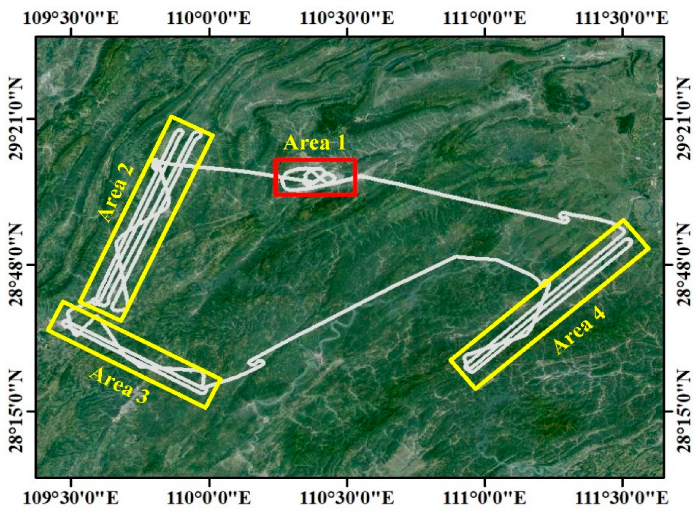
2.1. Experimental Study Area and Data Sources
2.1.1. Large-footprint Lidar Data
2.1.2. Other Data
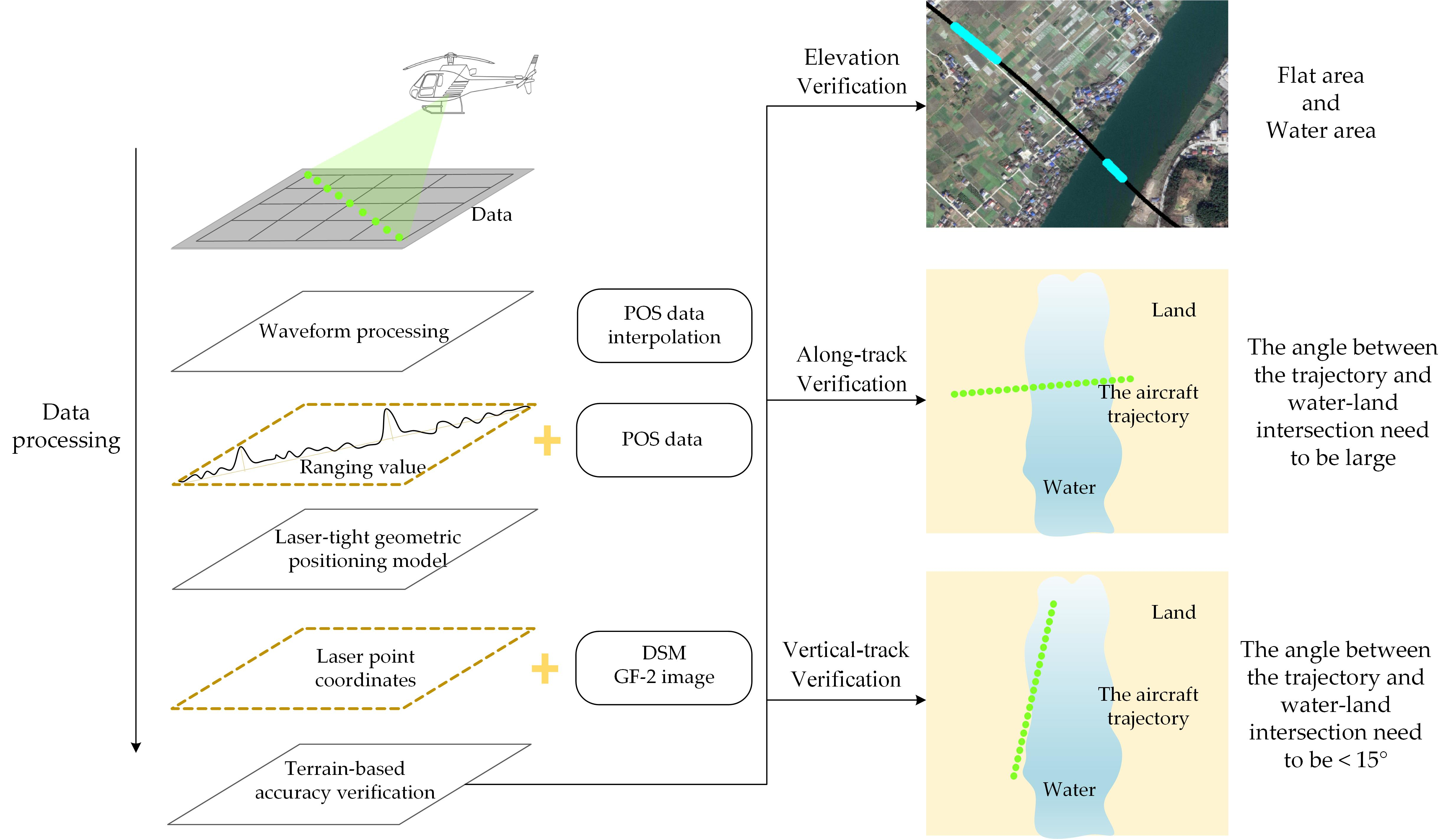
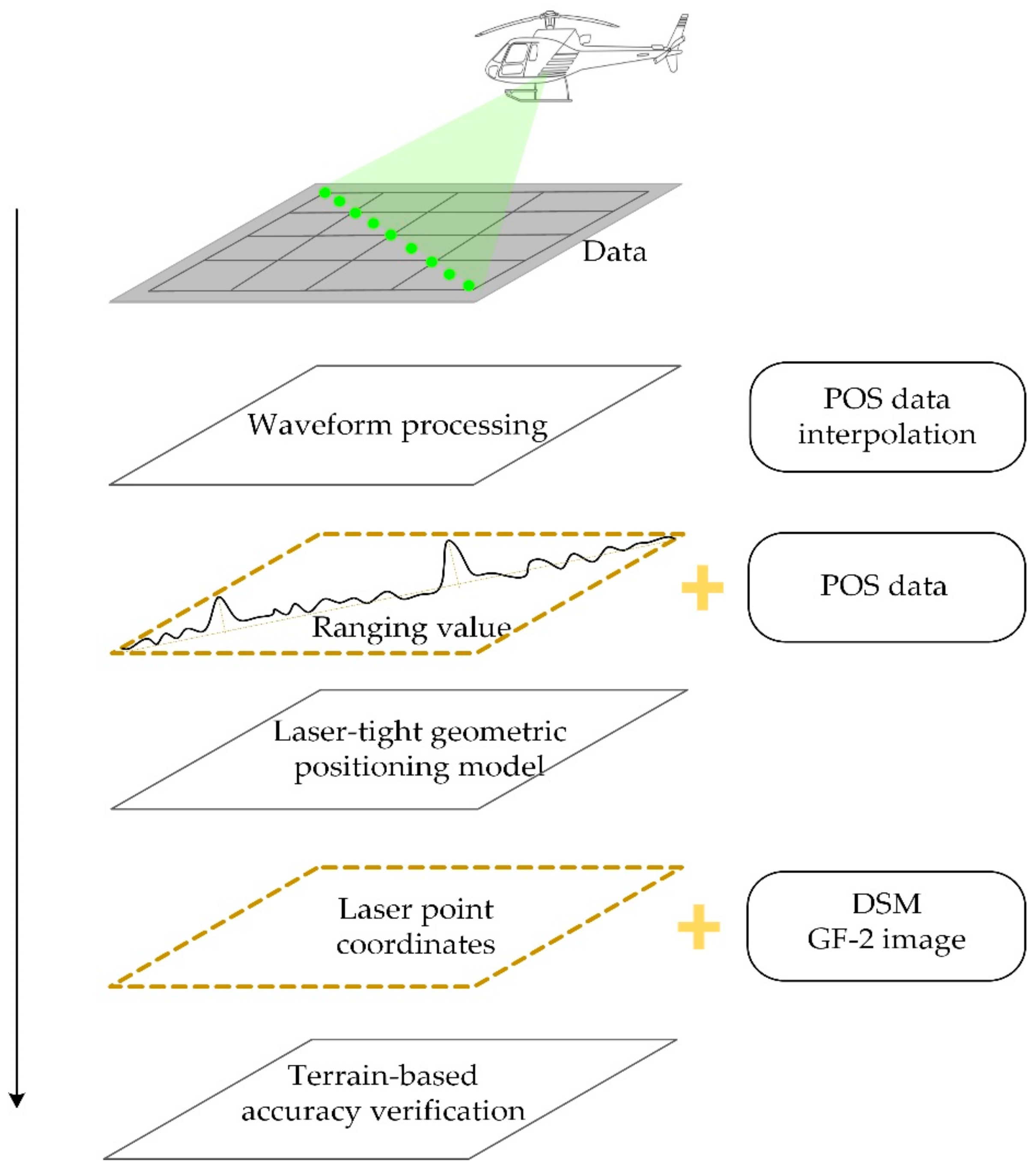
2.2. Data Processing
- Waveform data reading: The large-footprint lidar data and POS data are read. POS data are interpolated for consistency with the lidar waveform time.
- Waveform pre-treatment: The lidar data are pre-processed, including data interpretation and removal of waveform noise, in order to reduce the influence of noise on the positioning accuracy.
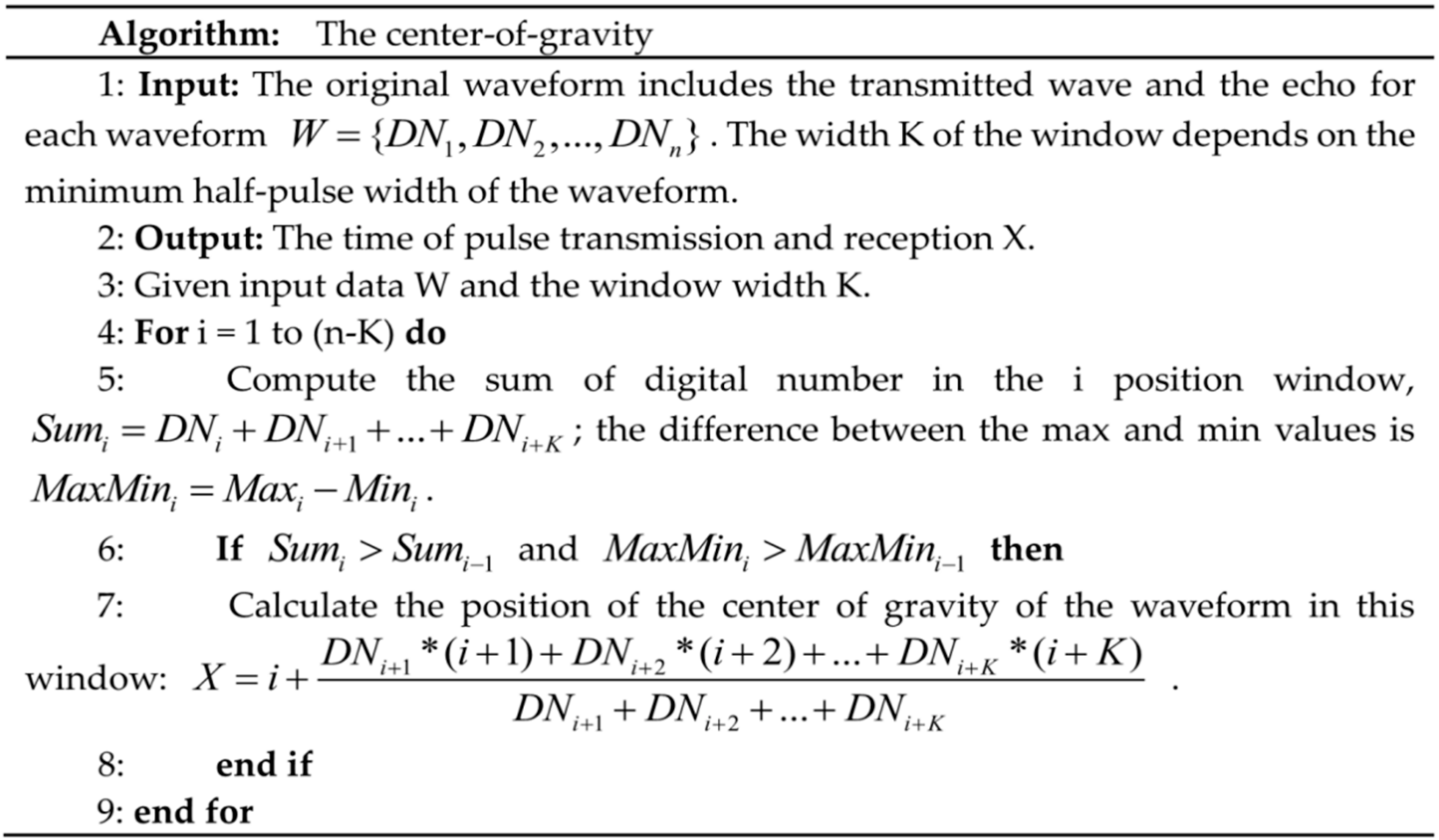
- Main peak extraction: To deal with echo signal saturation, the COG method is used to define the peaks of the incident wave and echo and relocate the main peak, allowing the distance between the laser and the measured object to be calculated according to the time of the incident wave and echo wave peak.
- Geometrical positioning: The laser-tight geometric positioning model is used to calculate the three-dimensional laser point coordinates by combining the ranging value and POS data.
- Accuracy verification: The terrain features are used to verify the elevation and plane accuracy of airborne lidar data.
2.2.1. Signal Saturation Processing
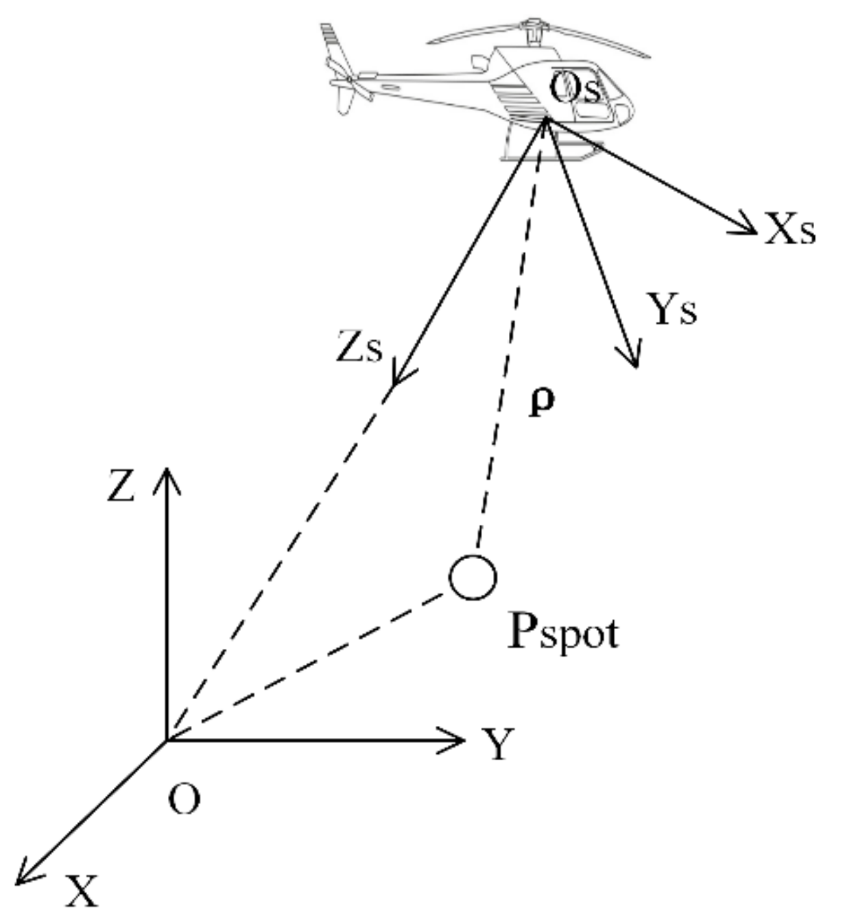
2.2.2. Laser-Tight Geometric Positioning Model
2.3. Accuracy Verification Method
2.3.1. Verification of Elevation Accuracy
2.3.2. Verification of Positioning Accuracy Along the Orbital Direction
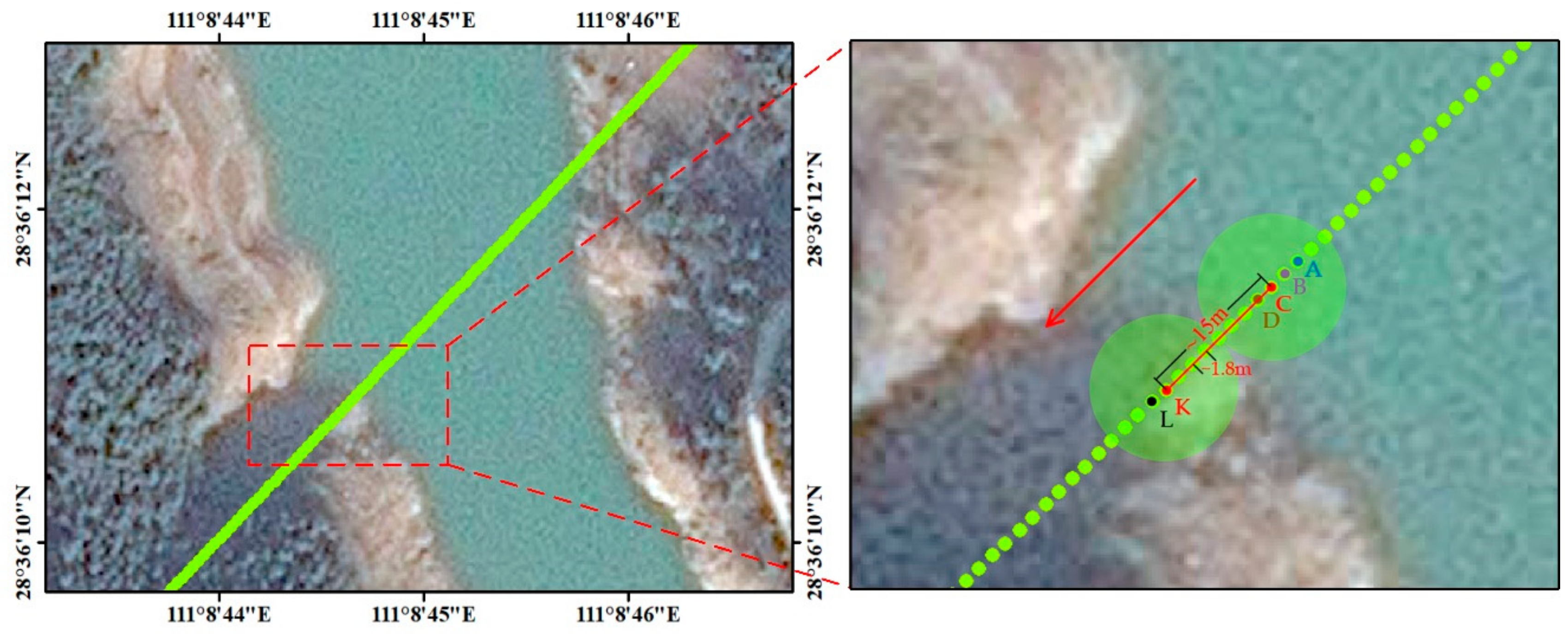
- Footprint selection: The laser spot location map is combined with the high-resolution remote sensing image, which enables an appropriate laser spot A on the water surface to be found through visual interpretation (Figure 6).
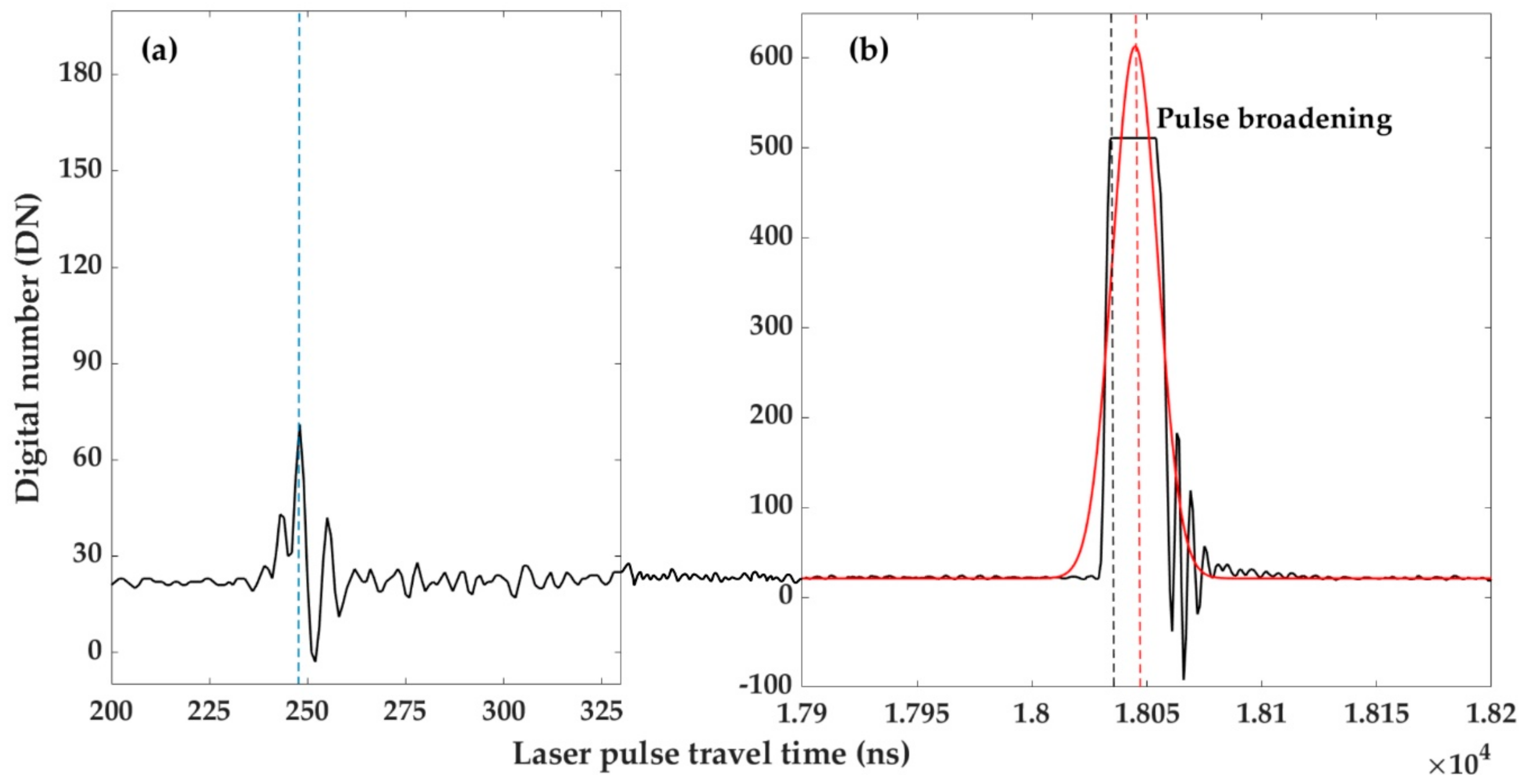
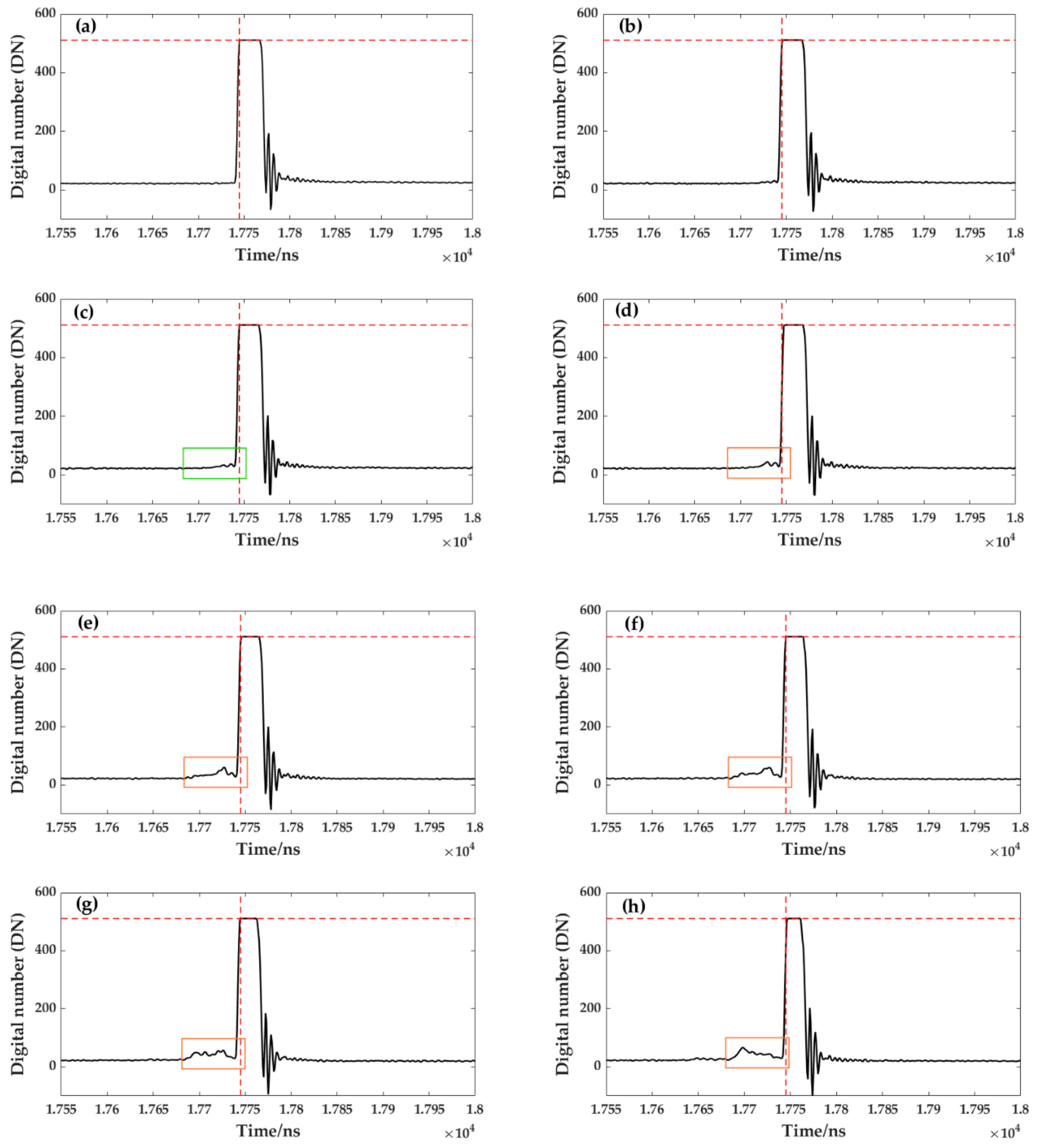
- Waveform search: The echo waveform corresponding to the selected spot A is assessed. Due to the high reflection intensity at the calm water surface, the echo signal corresponding to spot A is continuously saturated (Figure 7a). Marking the starting position of the spot saturation denotes the echo peak position of the water surface (red dotted line in Figure 7).
- Process backtracking: The corresponding waveform of each spot from the position of spot A is viewed in the landward direction. Figure 7 shows the echo waveform corresponding to each spot from A to I in Figure 6. When the feature covered by the footprint begins to appear on the land, the echo waveform will have two echoes, one from the water surface and the other from the land surface. Because the elevation of the land is higher than that of the water surface, the echo waveform on the land will appear in front of that from the water surface, according to the echo time (orange rectangle in Figure 7). When continuing to view the waveform of the laser spot in the landward direction, the saturation of the water spot weakens, as does the echo intensity until it disappears. Meanwhile, the amplitude of the land echo signal is gradually increasing.
- Footprint judgment: By observing the appearance of the land echo signal and the disappearance of the water echo signal, it is possible to judge that the footprint before the appearance of the land echo waveform is the last laser footprint that completely falls in the water surface; this can be defined as the footprint of the water surface. Similarly, when the wave peak at the water surface disappears completely, this footprint can be defined as the footprint of the land. However, due to the influence of noise or tree branches, it is not easy to determine the footprint where the land echo waveform begins to appear and where the water echo waveform completely disappears. For instance, the waveform before the echo peak position of the water surface of spot C is not obvious (green rectangle in Figure 7c), and it is not possible to determine whether this is a land echo or noise. Similarly, it is not easy to determine whether there is a water echo at the echo peak position of the water of spot K (blue rectangle in Figure 7k). Therefore, we combine the footprint spot diameter to assist the judgment. Because the footprint spot diameter is ~15 m, we require the center distance between the water and land footprints to be approximately 15 m when judging the two spots, which also ensures that the footprints of water and land are tangent. The spacing of the laser spots is ~1.8 m, spot C and spot K are separated by eight spaces, about 15 m. Therefore, we judge that the insignificant echo is noise and defined spot C as the footprint of the water surface and spot K as the footprint of the land surface.
- Error calculation: Because the footprints of water and land are tangent, the halfway point of the central line between the water and land footprint spots can be taken as the measured intersection position (Figure 6). Then, by finding the actual position of the boundary between the water and land surfaces using DSM data, the lidar positioning error along the track can be determined.
2.3.3. Verification of the Positioning Accuracy Perpendicular to the Orbital Direction
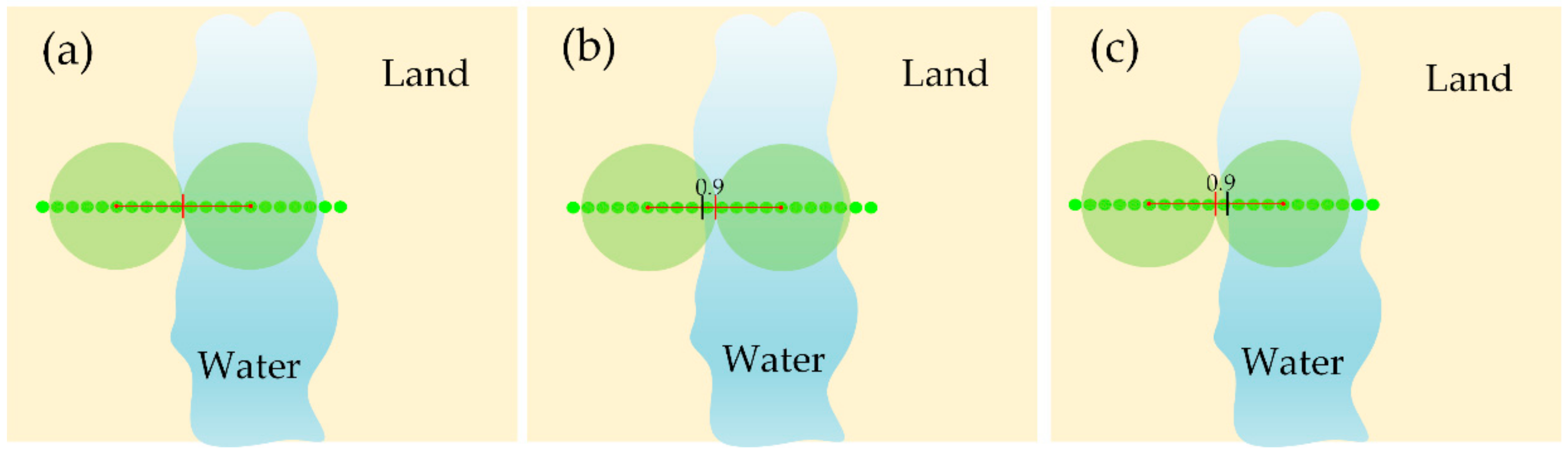
- Area selection: First, the laser spot location map is combined with the high-resolution remote sensing image, and trajectories with angles of < 15° with the water–land intersection are determined by visual interpretation (Figure 8).
- Waveform comparison: The waveform corresponding to the land footprint intersection with the trajectory is located. If the waveform diagram of the land is saturated, this means that the footprint spot has shifted to the land in the vertical orbit direction. Similarly, if the wave pattern corresponding to the footprint spot in the water is not saturated, this means that the footprint spot is offset toward the water in the vertical direction.
- Actual positioning: There is a certain elevation difference between water and land. Following the direction of the vertical track of the shifted spot, the location of the spot’s elevation can be determined through the elevation change of the DSM; this is the actual position.
- Error calculation: The difference between the offset spots on the route track and the actual position is determined, and the average error value is recorded as the vertical orbit positioning error.
3. Results
3.1. Verification of Laser Elevation Accuracy
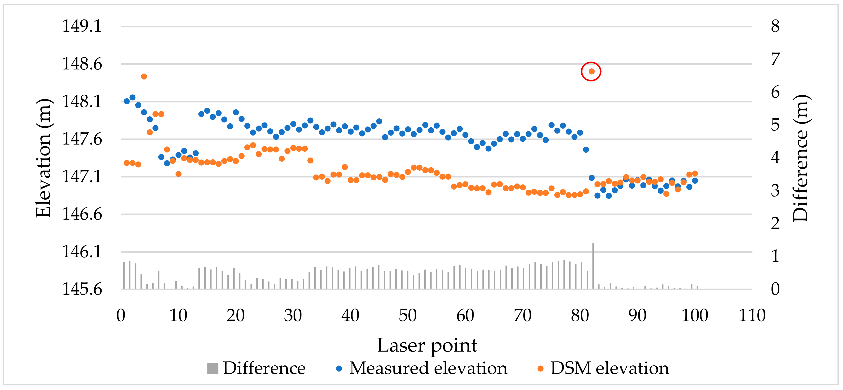
3.1.1. Flat Areas
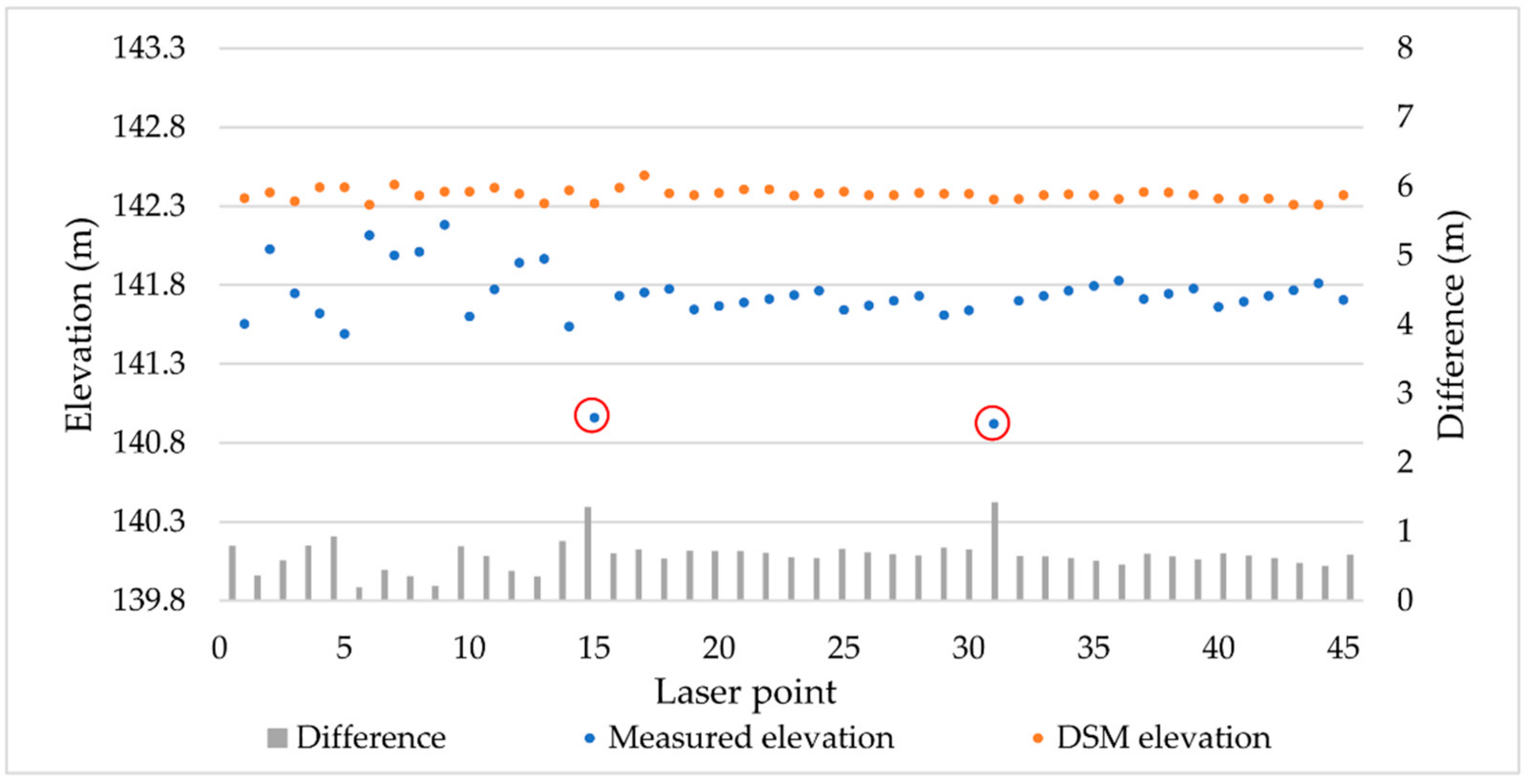
3.1.2. Water Areas
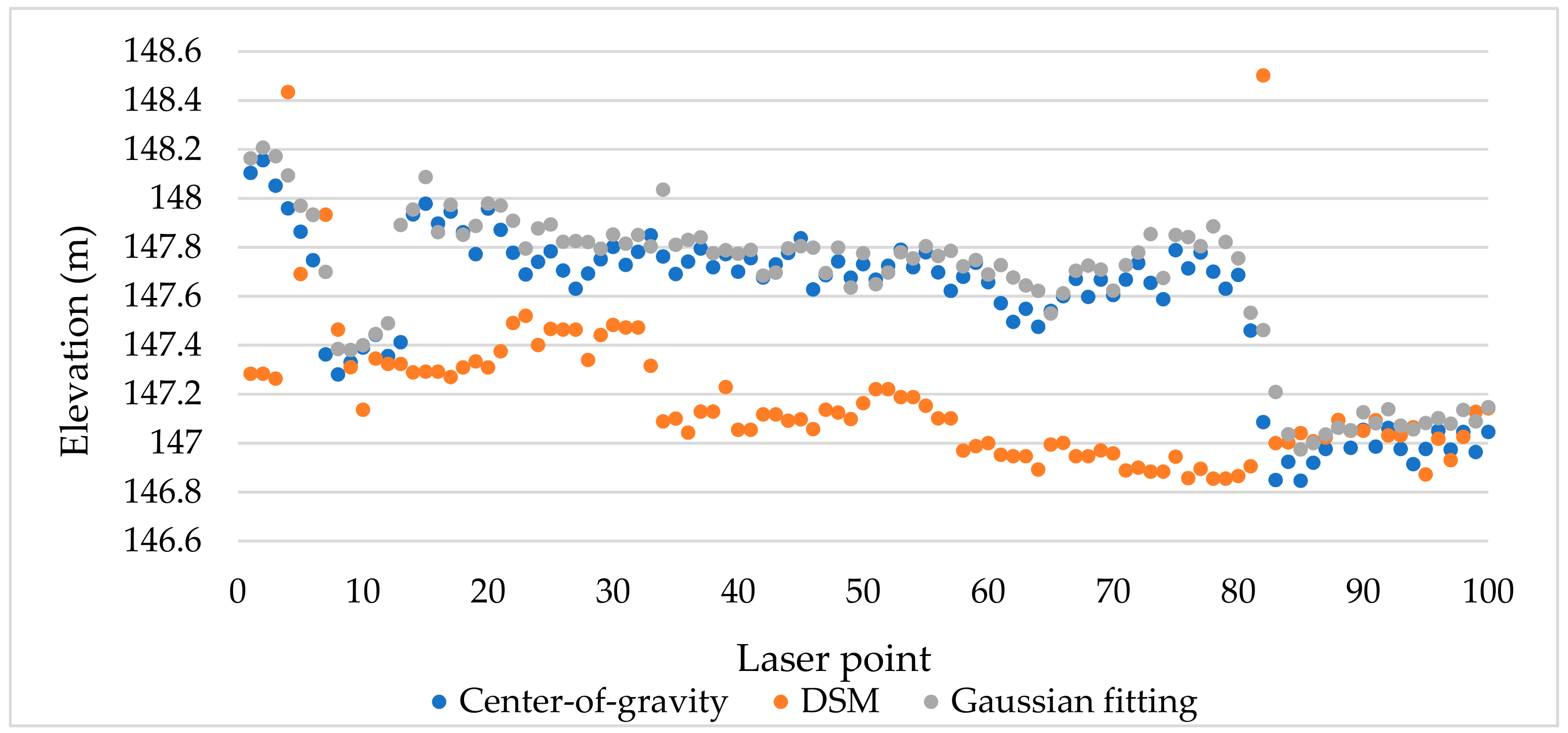
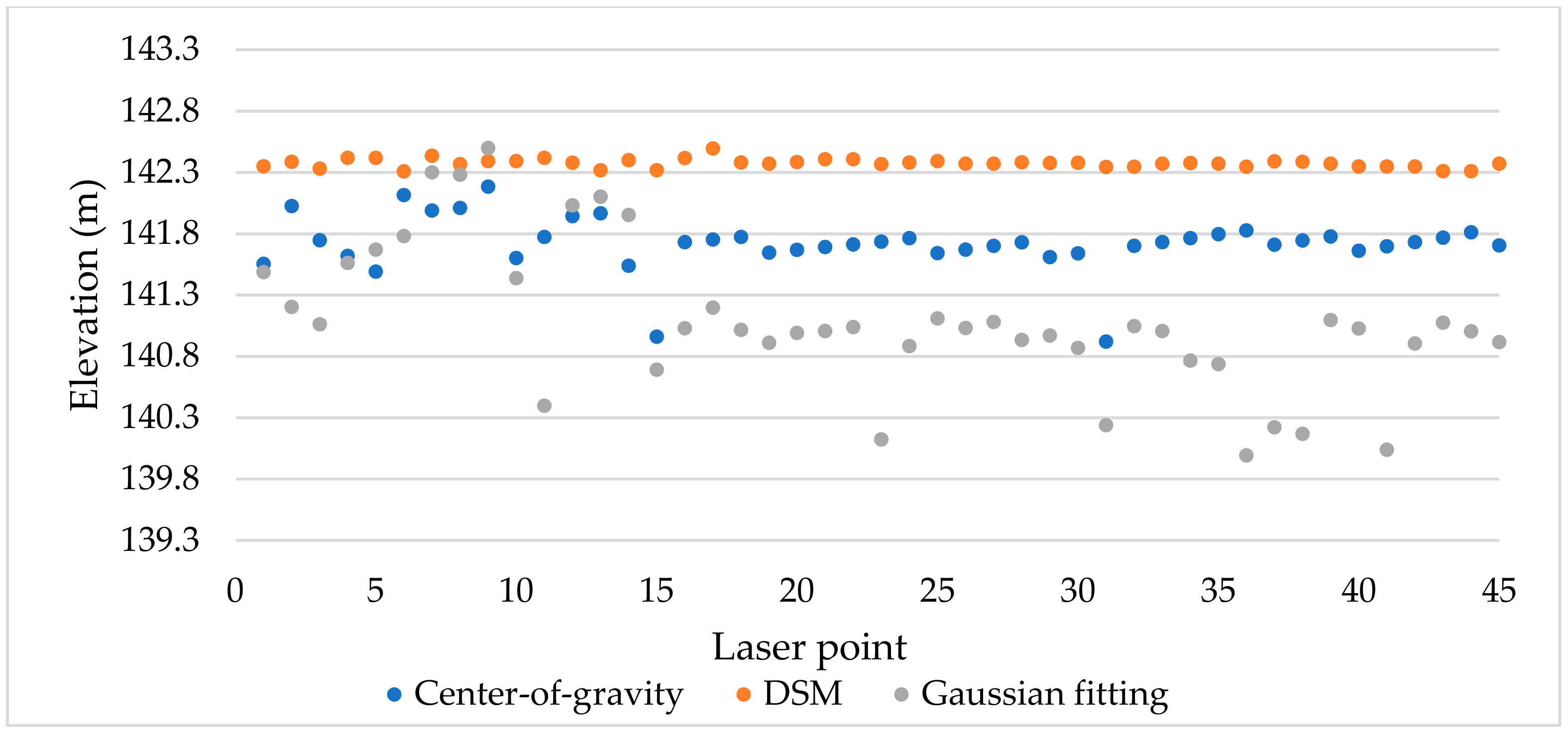
3.1.3. Effect of the COG Method
3.2. Verification of Laser Plane Accuracy
3.2.1. Along-track Verification
3.2.2. Vertical Track Plane Positioning Accuracy
4. Discussion
4.1. Data Processing Analysis
4.2. Evaluation of Accuracy Verification Method
4.2.1. Applicability Analysis
4.2.2. Error Analysis
5. Conclusions
Author Contributions
Funding
Acknowledgments
Conflicts of Interest
References
- Wang, C.; Menenti, M.; Stoll, M.P.; Li, C.; Tang, L. Error analysis & correction of airborne LiDAR data (in Chinese). J. Remote Sens. 2007, 3, 390–397. [Google Scholar]
- Tian, J.; Wang, L.; Li, X.; Yin, D.; Gong, H.; Nie, S.; Shi, C.; Zhong, R.; Liu, X.; Xu, R. Canopy Height Layering Biomass Estimation Model (CHL-BEM) with Full-Waveform LiDAR. Remote Sens. 2019, 11, 1446. [Google Scholar] [CrossRef]
- Fayad, I.; Baghdadi, N.; Bailly, J.-S.; Barbier, N.; Gond, V.; Hajj, M.E.; Fabre, F.; Bourgine, B. Canopy Height Estimation in French Guiana with LiDAR ICESat/GLAS Data Using Principal Component Analysis and Random Forest Regressions. Remote Sens. 2014, 6, 11883–11914. [Google Scholar] [CrossRef]
- Ali, S.A.; Sridhar, V. Deriving the Reservoir Conditions for Better Water Resource Management Using Satellite-Based Earth Observations in the Lower Mekong River Basin. Remote Sens. 2019, 11, 2872. [Google Scholar] [CrossRef]
- Chipman, J.W. A Multisensor Approach to Satellite Monitoring of Trends in Lake Area, Water Level, and Volume. Remote Sens. 2019, 11, 158. [Google Scholar] [CrossRef]
- Ferreira, L.G.; Urban, T.J.; Neuenschawander, A.; De Araújo, F.M. Use of Orbital LIDAR in the Brazilian Cerrado Biome: Potential Applications and Data Availability. Remote Sens. 2011, 3, 2187–2206. [Google Scholar] [CrossRef]
- Blair, J.B.; Rabine, D.L.; Hofton, M.A. The Laser Vegetation Imaging Sensor: A medium-altitude, digitization-only, airborne laser altimeter for mapping vegetation and topography. ISPRS J. Photogramm. Remote Sens. 1999, 54, 115–122. [Google Scholar] [CrossRef]
- Park, T.; Kennedy, R.E.; Choi, S.; Wu, J.; Lefsky, M.A.; Bi, J.; Mantooth, J.A.; Myneni, R.B.; Knyazikhin, Y. Application of Physically-Based Slope Correction for Maximum Forest Canopy Height Estimation Using Waveform Lidar across Different Footprint Sizes and Locations: Tests on LVIS and GLAS. Remote Sens. 2014, 6, 6566–6586. [Google Scholar] [CrossRef]
- Jansma, P.; Mattioli, G.; Matias, A. Slicer laser altimetry in the eastern Caribbean. Surv. Geophys. 2001, 22, 561–579. [Google Scholar] [CrossRef]
- Schutz, B.E.; Zwally, H.J.; Shuman, C.A.; Hancock, D.; DiMarzio, J.P. Overview of the ICESat mission. Geophys. Res. Lett. 2005, 32, L21S01. [Google Scholar] [CrossRef]
- Peterson, B.; Nelson, K.J. Mapping Forest Height in Alaska Using GLAS, Landsat Composites, and Airborne LiDAR. Remote Sens. 2014, 6, 12409–12426. [Google Scholar] [CrossRef]
- Fricker, H.A.; Borsa, A.; Minster, B.; Carabajal, C.; Bills, B. Assessment of ICESat performance at the Salar de Uyuni, Bolivia. Geophys. Res. Lett. 2005, 32, L21S06. [Google Scholar] [CrossRef]
- Smith, D.E.; Zuber, M.T.; Neumann, G.A.; Lemoine, F.G.; Mazarico, E.; Torrence, M.H.; McGarry, J.F.; Rowlands, D.D.; Head, J.W.; Duxbury, T.H.; et al. Initial observations from the Lunar Orbiter Laser Altimeter (LOLA). Geophys. Res. Lett. 2010, 37, L18204. [Google Scholar] [CrossRef]
- Li, G.; Tang, X. Analysis and validation of ZY-3 02 satellite laser altimetry data. Acta Geod. Et Cartogr. Sin. 2017, 46, 1939–1949. [Google Scholar] [CrossRef]
- Tang, X.; Xie, J.; Liu, R.; Huang, G.; Zhao, C.; Zhen, Y.; Tang, H.; Dou, X. Overview of the GF-7 laser altimeter system mission. Earth Space Sci. 2019, 7, 1–11. [Google Scholar] [CrossRef]
- Magruder, L.; Silverberg, E.; Webb, C.; Schutz, B. In situ timing and pointing verification of the ICESat altimeter using a ground-based system. Geophys. Res. Lett. 2005, 32, L21S04. [Google Scholar] [CrossRef]
- Magruder, L.A.; Suleman, M.A.; Schutz, B.E. ICESat laser altimeter measurement time validation system. Meas. Sci. Technol. 2003, 14, 1978–1985. [Google Scholar] [CrossRef][Green Version]
- Magruder, L.A.; Ricklefs, R.L.; Silverberg, E.C.; Horstman, M.F.; Suleman, M.A.; Schutz, B.E. ICESat geolocation validation using airborne photography. IEEE Trans. Geosci. Remote Sens. 2010, 48, 2758–2766. [Google Scholar] [CrossRef]
- Schutz, B.E. Calibration/Validation of ICESat laser altimeter (GLAS). In Proceedings of the American Geophysical Union, Spring Meeting 2002, Washington, DC, USA, 30 May 2002. [Google Scholar]
- Magruder, L.A.; Schutz, B.E.; Silverberg, E.C. Laser pointing angle and time of measurement verification of the ICESat laser altimeter using a ground-based electrooptical detection system. J. Geod. 2003, 77, 148–154. [Google Scholar] [CrossRef]
- Magruder, L.A.; Webb, C.E.; Urban, T.J.; Silverberg, E.C.; Schutz, B.E. ICESat altimetry data product verification at White Sands Space Harbor. IEEE Trans. Geosci. Remote Sens. 2007, 45, 147–155. [Google Scholar] [CrossRef]
- Zhang, G.; Li, S.; Huang, W. Geometric calibration and validation of ZY3-02 satellite laser altimeter System. Geomat. Inf. Sci. Wuhan Univ. 2017, 11, 92–99. [Google Scholar]
- Tang, X.; Xie, J.; Fu, X.; Mo, F.; Li, S.; Dou, X. ZY3-02 laser altimeter on-orbit geometrical calibration and test. Acta Geod. Et Cartogr. Sin. 2017, 46, 714–723. [Google Scholar] [CrossRef]
- Martin, C.F.; Thomas, R.H.; Krabill, W.B.; Manizade, S.S. ICESat range and mounting bias estimation over precisely-surveyed terrain. Geophys. Res. Lett. 2005, 32, 242–257. [Google Scholar] [CrossRef]
- Harding, D.J. ICESat waveform measurements of within-footprint topographic relief and vegetation vertical structure[J]. Geophys. Res. Lett. 2005, 32, L21S10. [Google Scholar] [CrossRef]
- Sun, X.; Abshire, J.B.; Borsa, A.A.; Fricker, H.A.; Yi, D.; DiMarzio, J.P.; Paolo, F.S.; Brunt, K.M.; Harding, D.J.; Neumann, G.A. ICESAT/GLAS altimetry measurements: Received signal dynamic range and saturation correction. IEEE Trans. Geosci. Remote Sens. 2017, 55, 5440–5454. [Google Scholar] [CrossRef]
- Wu, F.; Gao, X.; Pan, C. Design and application of forest detecting based on airborne large-footprint LiDAR system. For. Res. Manag. 2018, 125–132. [Google Scholar] [CrossRef]
- Chen, X. Waveform processing and accuracy verification of airborne large-footprint LiDAR system. Master’s Thesis, Wuhan University, Wuhan, China, 2019. [Google Scholar]
- Zhou, H.; Chen, Y.; Hyyppa, J.; Li, S. An overview of the laser ranging method of space laser altimeter. Infr. Phys. Technol. 2017, 86, 147–158. [Google Scholar] [CrossRef]
- Abshire, J.B.; Sun, X.; Riris, H.; Sirota, J.M.; McGarry, J.F.; Palm, S.; Yi, D.; Liiva, P. Geoscience laser altimeter system (GLAS) on the ICESat mission: On-orbit measurement performance. Geophys. Res. Lett. 2005, 32, 2–21. [Google Scholar] [CrossRef]
- ICESat/GLAS Data: Description of Past Data Releases. National Snow and Ice Data Center. Available online: http://nsidc.org/data/icesat/past_releases.html (accessed on 15 December 2019).
- Brenner, A.C.; Zwally, H.J. The algorithm theoretical basis document for the derivation of range and range distributions from laser pulse waveform analysis for surface elevations, roughness, slope, and vegetation heights. Available online: https://nsidc.org/data/icesat/technical-references (accessed on 15 December 2019).
- Li, G. Earth observing satellite laser altimeter data processing method and engineer practice. Ph.D. Thesis, Wuhan University, Wuhan, China, 2017. [Google Scholar]
- Tang, X.; Li, G.; Gao, X.; Chen, J. The rigorous geometric model of satellite laser altimeter and preliminarily accuracy validation. Acta Geod. Et Cartogr. Sin. 2016, 45, 1182–1191. [Google Scholar] [CrossRef]
- Li, S. Research on geometric calibration of Earth observation satellite laser altimeter. Ph.D. Thesis, Wuhan University, Wuhan, China, 2017. [Google Scholar]
- Hassan, A.; Mustafa, E.K.; Mahama, Y.; Damos, M.A.; Jiang, Z.; Zhang, L. Analytical Study of 3D Transformation Parameters Between WGS84 and Adindan Datum Systems in Sudan. Arab J Sci Eng 2020, 45, 351–365. [Google Scholar] [CrossRef]
- Wand, D.; Pang, B.; Xiao, W. GEO space debris flux determination based on earth-fixed coordinate system. Acta Astronaut. 2017, 130, 60–66. [Google Scholar] [CrossRef]


| Equipment | Indicator Name | Design Value | Measured Value |
|---|---|---|---|
| Laser | Emission wave | 1064 nm | 1064.1 nm |
| Energy | 2 mJ | 2.03 mJ | |
| Emission angle | 5 mrad | X = 5.06 mrad Y = 5.12 mrad | |
| Pulse width | 1.5 ns | 1.57 ns | |
| Multi-pulse | 40 Hz | 40 Hz | |
| M2 | X ≤ 3 | X = 2.954 | |
| Y ≤ 3 | Y = 2.736 | ||
| Telescope | Aperture | 100 mm | 100 mm |
| Field of view | 6 mrad | 6 mrad | |
| Detector, signal acquisition, and processing subsystem | FWHM | 10 nm, transmittance ≥ 0.7 | Design assurance |
| Diameter of photosensitive surface | 0.8 mm | Design assurance | |
| Detector bandwidth | ≥ 100 MHz | 112.5 MHz | |
| Detector | APD | Design assurance | |
| Sampling rate | 1 GHz | 1 GHz |
| Area | COG (m) | Gaussian Fitting (m) | ||
|---|---|---|---|---|
| Mean Error | RMSE | Mean Error | RMSE | |
| Flat area | 0.39 | 0.55 | 0.48 | 0.59 |
| Water | 0.65 | 0.69 | 1.29 | 1.41 |
| Area | Track Number | Mean Error (m) | Area | Track Number | Mean Error (m) | Area | Track Number | Mean Error (m) |
|---|---|---|---|---|---|---|---|---|
| 2 | 154,413 | 4.16 | 3 | 140,440 | 1.8 | 4 | 113,154 | 4.25 |
| 2 | 150,248 | 3.6 | 3 | 134,814 | 5.4 | 4 | 115,821 | 4.6 |
| 2 | 153,335 | 1.7 | 3 | 134,814 | 4.2 | 4 | 115,821 | 4.7 |
| 2 | 160,717 | 2.76 | 3 | 133,352 | 0.7 | 4 | 115,821 | 2.5 |
| 2 | 160,717 | 3.56 | 3 | 133,021 | 3.9 | 4 | 114,309 | 1.54 |
| 2 | 150,516 | 4 | 3 | 141,622 | 2.8 | 4 | 114,309 | 2.33 |
| Average mean error (m) | 3.30 | 3.13 | 3.32 | |||||
| Track Number | 114,309 | 113,803 | 113,803 | 114,309 | 133,352 |
|---|---|---|---|---|---|
| Mean error (m) | 4.18 | 4.36 | 3.94 | 4.04 | 4.31 |
© 2020 by the authors. Licensee MDPI, Basel, Switzerland. This article is an open access article distributed under the terms and conditions of the Creative Commons Attribution (CC BY) license (http://creativecommons.org/licenses/by/4.0/).
Share and Cite
Lian, W.; Li, S.; Zhang, G.; Wang, Y.; Chen, X.; Cui, H. Accuracy Verification of Airborne Large-Footprint Lidar based on Terrain Features. Remote Sens. 2020, 12, 879. https://doi.org/10.3390/rs12050879
Lian W, Li S, Zhang G, Wang Y, Chen X, Cui H. Accuracy Verification of Airborne Large-Footprint Lidar based on Terrain Features. Remote Sensing. 2020; 12(5):879. https://doi.org/10.3390/rs12050879
Chicago/Turabian StyleLian, Weiqi, Shaoning Li, Guo Zhang, Yanan Wang, Xinyang Chen, and Hao Cui. 2020. "Accuracy Verification of Airborne Large-Footprint Lidar based on Terrain Features" Remote Sensing 12, no. 5: 879. https://doi.org/10.3390/rs12050879
APA StyleLian, W., Li, S., Zhang, G., Wang, Y., Chen, X., & Cui, H. (2020). Accuracy Verification of Airborne Large-Footprint Lidar based on Terrain Features. Remote Sensing, 12(5), 879. https://doi.org/10.3390/rs12050879