Article

PhotonLabeler: An Inter-Disciplinary Platform for Visual Interpretation and Labeling of ICESat-2 Geolocated Photon Data

Department of Ecology and Conservation Biology, Texas A&M University, College Station, TX 77598, USA
*
Author to whom correspondence should be addressed.
Remote Sens. 2020, 12(19), 3168; https://doi.org/10.3390/rs12193168
Submission received: 11 August 2020 / Revised: 13 September 2020 / Accepted: 23 September 2020 / Published: 27 September 2020

Abstract

:
NASA’s ICESat-2 space-borne photon-counting lidar mission is providing global elevation measurements that will provide significant benefits to a variety of ecosystem related research applications. Given the novelty of elevation and the derived data products from the ICESat-2 mission, the research community needs software tools that can facilitate photon-level analyses to support product validation and development new analysis methods. Here, we describe PhotonLabeler, a free graphic user interface (GUI) for manual labeling and visualization of ICESat-2 Geolocated Photon data (ATL03). Developed in MATLAB, the GUI facilitates the reading and display of ATL03 Hierarchical Data Format (HDF) files, the manual labeling of individual photons into target classes of choice using a number of point selections tools and enables eventual saving of labeled data in ASCII format. Other capabilities include saving and loading of labeling sessions to manage labeling tasks over time. We expect labeled data generated using the application to serve two main purposes. First, serve as reference data for validating various products from ICESat-2 mission, especially for study sites around the world that do not have existing reference datasets such as airborne lidar. Second, serve as training and validation data in the development of new algorithms for generating various ICESat-2 data products. We demonstrate the first use case through a validation case study for the land and vegetation product (ATL08), which provides canopy and terrain height estimates, over two sites. For the first site, located in northwestern Zambia, we used ICESat-2 ATL03 data acquired at night and for our second site in Texas, US, we used ATL03 data acquired during the day. ATL08 canopy and terrain height data showed good agreement (mean R2 > 0.8) with corresponding height metrics generated from manually labeled data. A comparison between PhotonLabeler and ATL08 photon labels also showed good agreement −93.3% and 95.4% overall accuracies for the Texas and Zambia site, respectively. These results, while limited in scope, show how PhotonLabeler can facilitate photon-level analyses for ICESat-2 data products beyond the ATL08 product. The PhotonLabeler application is freely available as a compiled MATLAB binary to enable free access and utilization by interested researchers.

Graphical Abstract

1. Introduction

NASA’S ICESat-2 (Ice, Cloud, and land Elevation Satellite-2) space-borne lidar mission launched in September 2018. A follow-on spaceborne lidar mission to the first ICESat mission, ICESat-2 carries the Advanced Topographic Laser Altimeter System (ATLAS) lidar instrument, a photon-counting lidar that uses a green (532 nm) laser for range measurement. The ATLAS instrument has notable advantages over its predecessor GLAS sensor including a reduced laser footprint (~14–17 m diameter reduced from ~70 m diameter) and an increased along-track sampling through higher pulse-repetition rate (10 kHz or about 0.70 m footprint spacing). Other improvements include the increased across-track sampling by partitioning the emitted laser into multiple profiling strong and weak beams [1,2]. Since its launch, ATLAS has provided unprecedented high-resolution three-dimensional along-track measurements of ice sheets [3,4], vegetation canopies [5,6], inland water [7], and clouds [1] providing opportunities for transformational Earth science and vegetation science research.
The single-photon counting technique utilized by ATLAS differs in a fundamental way from conventional lidar sensing as ranging is achieved at an individual photon scale as opposed to sensing energy peaks of backscattered laser energy [8]. Using photon time of flight values and measurements from ancillary systems such as GPS each photon is precisely geolocated by determining its time, latitude, longitude, and height to generate the Geolocated Photon Data (ATL03) [9]. Photons reflected from the surface along with those from the atmosphere or solar radiation are detectable which usually results in a combination of signal and noise photons. Thus, ATL03 data tends to exhibit higher levels of noise for daytime acquisition given the higher impact of solar background illumination [8,10]. Notwithstanding the presence of noise in the data, ICESat-2 mission, being a space-based instrument, has improved the possibility to characterize the Earth’s surface from local to global scales. Utilizing the 532 nm wavelength on the ATLAS instrument has also created opportunities for both surface and bathymetric mapping as the green energy can also penetrate water and interact with the sub-surface in addition to its surface and vegetation interactions [6,11,12]. ICESat-2 ATL03 photon data is enabling the generation of various standard data products for land ice, sea ice, the atmosphere, vegetation and land, oceans and inland water applications, which are available from the National Snow and Ice Data Center (NSIDC) website (https://nsidc.org/data/icesat-2/data-sets).
The availability of ICESat-2 products has spurred various studies to validate the products [5], develop alternative algorithms to generate similar datasets [2] or derive other products based on available products [6]. In those studies, the availability of reference data is a critical component to enable comparisons with existing products or assessment of developed algorithms, and airborne lidar data predominantly played this vital role. In Wang et al. [12], airborne lidar data were used to validate ground elevation and vegetation heights from the ATL08 product. Similar assessments have been carried out for land and vegetation height metrics [5]. Some studies also used airborne lidar data to simulate ICESat-2 data prior to launch of the mission to enable development of noise filtering algorithms [2]. However, airborne lidar data are not available in all areas or might be outdated to allow for an objective evaluation of current ICESat-2 products. In addition, there are assessments that may require a photon level understanding such as noise filtering, photon classification or assessing sources of error that airborne lidar data might not adequately support. In such cases, expert manually labeled photon data developed by direct interpretation of raw ATL03 photon data can facilitate such analyses. Manually labeled data also eliminates positional errors due the reference data, which enhances the overall analysis. Visual interpretation of data is not new in remote sensing and has supported various studies where reference data were not available [13,14,15]. Manually labeling photons is analogous to aerial photo interpretation consisting in identification of features in remote sensing images through visual interpretation. Scientific software tools allowing the display and labeling of photon data would enhance the development of labeled datasets to support product validation and development of analysis methods.
In this study, we describe PhotonLabeler, a new free software tool for labeling and visualization of ATLAS geolocated photon data. Other software tools for working with ICESat-2 data are available including PhoReal (https://github.com/icesat-2UT/PhoREAL) and web-based OpenAltimetry platform (https://openaltimetry.org/). These tools have focused mainly on the visualization of ICESat-2 data, data sub-setting, and format conversion, but do not offer labeling functionality as designed in the PhotonLabeler. The PhotonLabeler can support development of labeled reference data for a variety of assessments including ice, land, and vegetation elevation worldwide. The tool also serves as a platform for development of new or alternative algorithms for deriving various height measurements from ICESat-2 geolocated photon data by facilitating the collection of needed training data. We describe the general functionality of the application including reading and display of ATL03 data, labeling individual photons, and exporting labeled data for further analyses. To demonstrate applicability of this software to suggested assessments, we also include a case study for validating canopy and terrain heights from the ATL08 product. We collected labeled photon data using PhotonLabeler from ICESat-2 ATL03 data over two sites, one in northwestern Zambia and the other in eastern Texas in the United States and compared height estimates generated from them with ATL08 height estimates.

2. Materials and Methods

2.1. ATL03 Data

2.1.1. Data Description and Organization

ICESat-2 ATL03 data, in HDF format, are the main input to the PhotonLabeler application for visualization and labeling. ATL03 data (https://nsidc.org/data/atl03) provide time, latitude, longitude, and ellipsoidal height for each detected photon in the WGS-84 reference frame. The ATL03 data are organized by ground track, with ground tracks 1L and 1R forming the first pair, ground tracks 2L and 2R forming middle pair, and ground tracks 3L and 3R forming last or third pair [9]. The designation of which track is weak or strong depends on the direction of travel of ATLAS (Figure 1)—in forward orientation strong beams are mapped to the right (R) beams and weak beams to the left (L) tracks, and vice versa [9]. All the point data for each respective ground track can be accessed from the heights sub-group (/gtx/heights). For more details about the configuration of the ground tracks and data attributes in the ATL03 HDF file, we refer an interested reader to the ATL03 Algorithm Theoretical Basis document (ATBD) [9].

2.1.2. Visualizing and Interpreting ATL03 Data

ATL03 data are profiling data, thus provide sample cross-sectional views of the observed area. As such, ATL03 data are usually visualized by plotting photon elevation values (y-axis) against time or along-track distance (ATD) values (x-axis) (Figure 2). ATL03 data could also be visualized in 3D space by plotting latitude, longitude, and elevation values. For interpretation and labeling purposes, 2D views are generally sufficient.
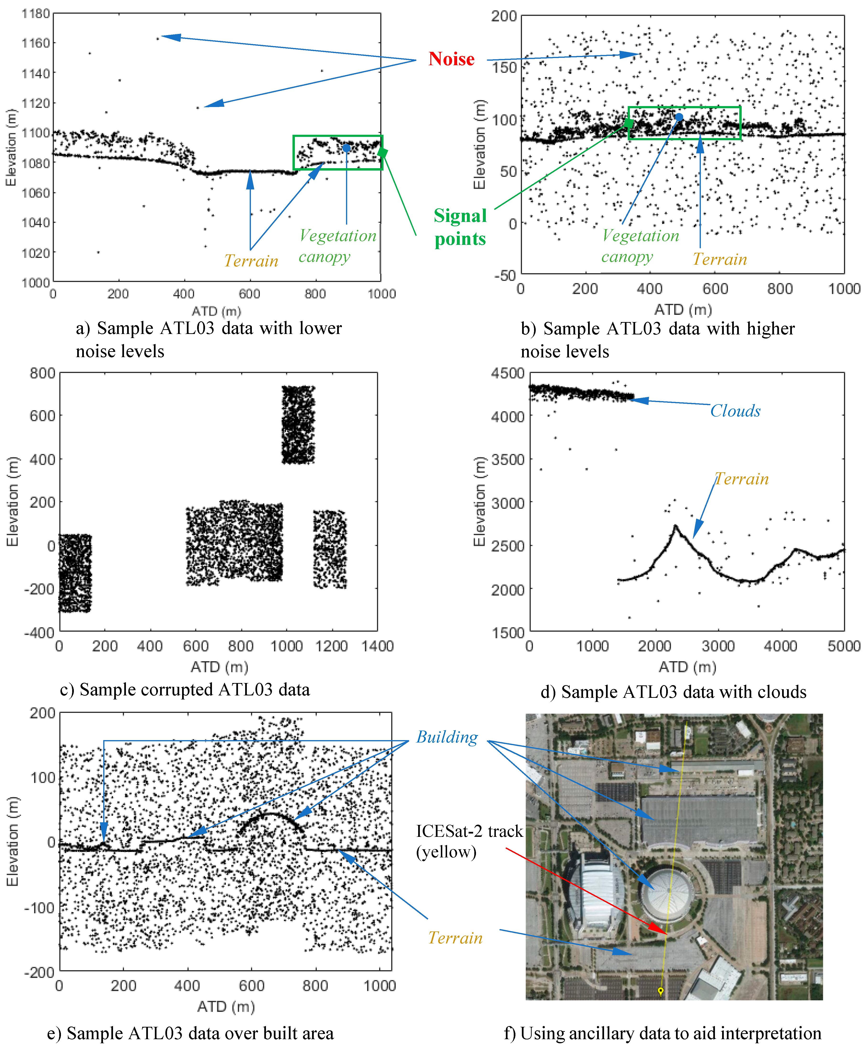
Plotting ATL03 data provides a convenient way for interpreting them into classes of interest. It is noteworthy to state that no studies have published formal guidelines for interpreting ATL03 or profiling lidar data as the case for image interpretation. Here, we provide some tips borne mostly from our experience with ATL03 data and knowledge from similar profiles generated across airborne lidar data. Unlike scanning-based lidar data with spatially complete coverage, the 3D visual cues such as shape, texture, and color that users rely on to readily interpret various objects in the data are diminished for ATL03 data. Nevertheless, it is still feasible to interpret individual or group of points in ATL03 data into a variety of classes including terrain, vegetation canopy, building roof, clouds, and so on. As in image interpretation, recognizing various objects or surfaces in plotted ATL03 data and an understanding of how the sensing energy interacts with various target objects (water, clouds, vegetation etc.) are critical for successful interpretation and labeling. Foremost, an interpreter should be able to recognize signal and noise points given that observing differences in the spatial distribution of points is one of the convenient ways of differentiating them. When ATL03 data are plotted on a Euclidean space, signal points (real data) tend to cluster together compared to noise points which tend to be randomly distributed in space (Figure 2a,b). Sometimes, ATL03 data are corrupted by instrument or geolocation errors, resulting in unnatural discontinuities and offsets in the data (Figure 2c). Such data sections are usually unusable and could also be interpreted as noise.
Signal points could further be interpreted into terrain (e.g., land or sea ice terrain), above-terrain point classes (e.g., forest canopies, buildings, and clouds) and below-terrain surfaces (e.g., bathymetry) by leveraging attributes specific to the data and using ancillary data. For instance, elevation relationships among points or point clusters (e.g., points on vegetation canopies should lie above terrain points, cloud points usually cluster together but have very high elevations above terrain, Figure 2a,b,d), shape (regularity of building roof surfaces, Figure 2e) and point distribution information (terrain points show lower local elevation variance than points on vegetation, Figure 2a,b,d) could be applied for effective interpretation. Reduction in point density for weak beams can pose interpretation challenges but observing data in a corresponding strong beam could aid interpretation even though they two beams do not sample the same area. While interpretation of ATL03 data could largely be done based on ATL03 data themselves, using ancillary data such as high-resolution imagery could enhance interpretation by applying the visual cues normally applied in image interpretation (Figure 2f and Figure 3).

2.2. PhotonLabeler User Interface (UI) and Software Capabilities

2.2.1. UI Layout Overview and Display Control

We developed the PhotonLabeler UI and associated functionality using the MathWorks MATLAB App Designer (MATLAB R2020a). Figure 4 shows the three-panel layout of the PhotonLabeler UI. The left panel shows ground track details such as the beam level (weak or strong), the number of points in the track and the distance spanned. The panel also contains tools for defining or loading saved label definitions and displaying label statistics. The central panel contain two plot axes: the Overview and the Detail plots. We adopted the two-plot view to enhance the interpretation and labeling of individual photons by providing both an overview of the loaded data across a larger extent, and a more detailed view across a smaller extent. The left-most panel contains tools for data display control such as the size of the delta time or along-tract distance (ATD) span, the zFactor, which controls the portion of data to display in the Detail plot and an option that controls whether to use delta time or ATD values on the x-axis. This panel also contains a number of point selection tools to facilitate labeling. In the following sections, we outline the general workflow and critical parameters that enable the reading, labeling and export of labeled data. For details on various functionality in the software, please refer to the supplementary material.

2.2.2. Reading and Visualization of ATL03 Data in PhotonLabeler

The PhotonLabeler application reads and displays ATL03 HDF data by ground track and displays the data by plotting either the photon delta time values or the calculated along-track distance (ATD) values on the x-axis against the photon elevation values on the y-axis. To manage large file sizes, the PhotonLabeler only loads a portion of the data at a given time. Two parameters control how much data is loaded in the Overview and Detail plots: ∆T size parameter, which defines span of the data on x-axis and the zFactor parameter or zoom factor, which is a factor by which ∆T size is equally divided. All data that lies within a specified ∆T size range are loaded in the Overview plot. From the data loaded in the Overview plot, a sub-portion equal to ∆T size/zFactor is then loaded in the Detail plot, allowing a user to step through using the Next and Back buttons to view all data loaded in the Overview plot. At any point, the blue semi-transparent region in the Overview plot highlights the data displayed in the Detail plot as a guide when exploring or labeling the data. A user may also drag the blue region to positions of interest instead of using the Next and Back buttons to navigate through the data.
PhotonLabeler application provides two methods for calculating ATD values. The first approach, which is the faster approach, uses an approximate relationship between delta time and the distance (1 s ≈ 7000 distance m) covered by the ICESat-2 satellite on the ground. Differenced delta time values are multiplied by the conversion factor (7000) and accumulated from the first point to generate along-track distances. This approach treats all points as lying on a common track, thus neglects across variation within the footprint. The other approach generates a best-fit line among the points in the dataset and projects all points to this common line. Inter-point distances are then calculated and accumulated to get along-track distances. Due to the higher number of computations, this approach is usually slow. For visualization and labeling purposes, the first approach is adequate and is recommended.
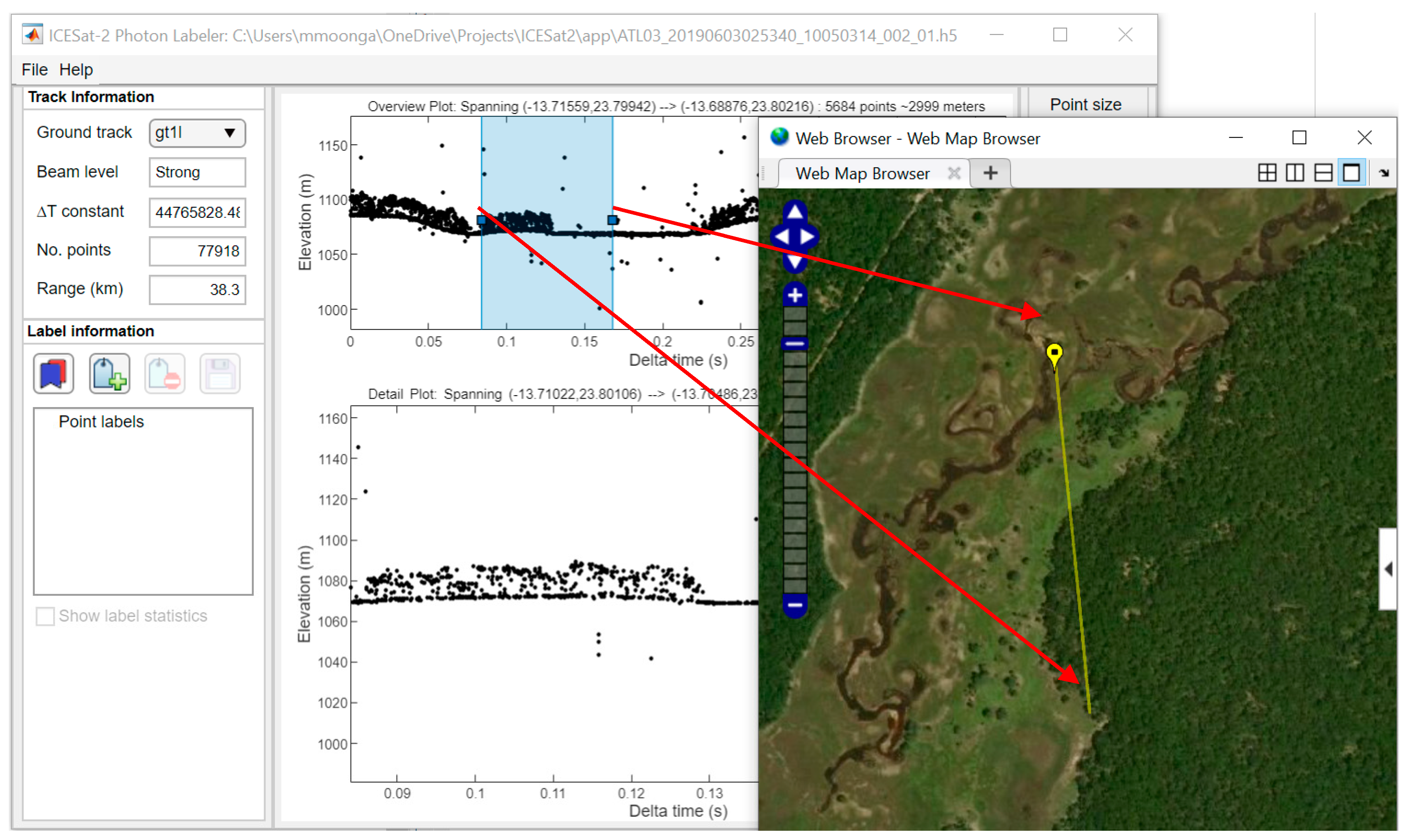
As an aid to photon labeling or general data exploration in different part of the world, the PhotonLabeler application provide the means to link to base maps through MATLAB’s web maps as illustrated in Figure 3. In the figure, the yellow line shows the portion of the track covered by data in the Detail plot with the yellow marker indicating the direction of the track. Using visual cues from ATL03 data as displayed in the Overview and Details plots and high-resolution imagery provide a powerful tool for effective photon interpretation and labeling.

2.2.3. Creating a Point Label Definition, Selecting, and Labeling Points

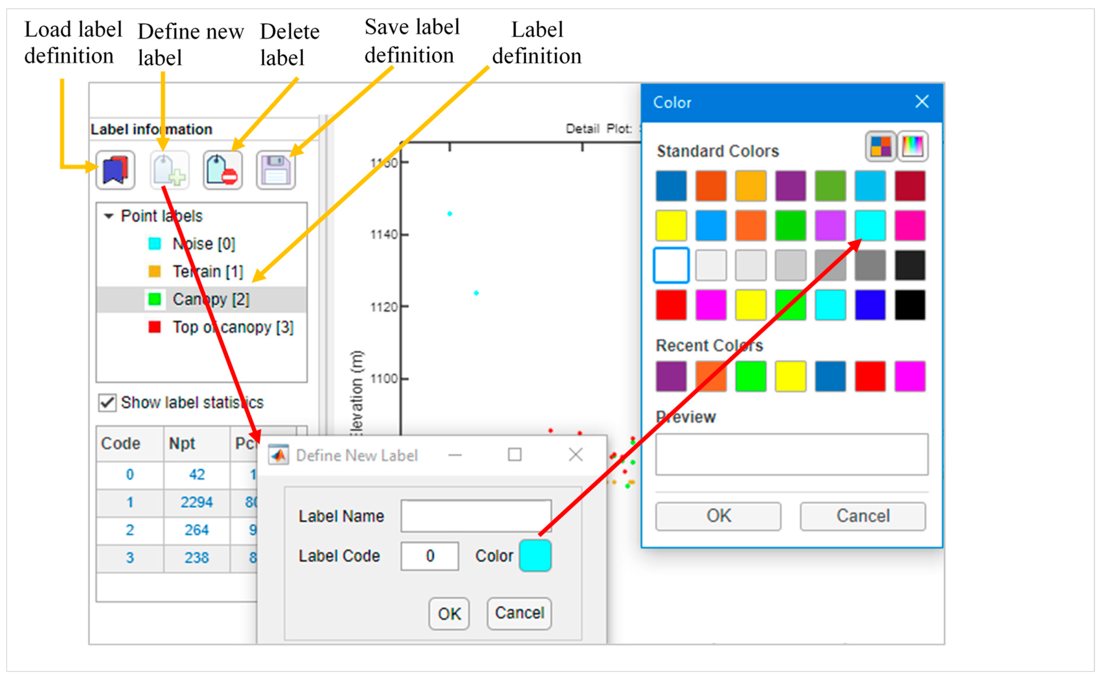
To manage labeling tasks, PhotonLabeler provides tools for defining point label definitions. A point label definition or scheme defines point classes and their respective representation for a target application. A user can define individual point class representation by specifying the label name, label code and picking a representation color as illustrated in Figure 5. PhotonLabeler also offers tools for deletion of defined point labels, saving of and loading of saved point label scheme. A saved label definition could be loaded when specifying session options or through the Load label definition button (Figure 5). Figure 5 shows an example of a classification scheme for vegetation study were target groups include noise, terrain, canopy, and top of canopy. Defining a point label definition is only critical to labeling but is not required for mere visualization and general exploration of the loaded dataset.
The PhotonLabeler implements photon labeling on a track-by-track basis. A number of point selection tools including rectangle, polygon, and polyline-based tools are available to facilitate the labeling of individual or group of photons. Normally, a user selects a target class and uses any of the available tools to select points of interest. Once the user has selected the points, the selected points are labeled and visualized based on a current active class. The user has the option to undo or reset recently labeled or all labeled data. The PhotonLabeler also provides an option to define top of canopy (ToC) points automatically, through the Assisted ToC Selection option (Figure 4), for vegetation related assessments. Based on the region of interest defined by the user, top of canopy points are defined by binning (see Bin Interval in Figure 4) the data along the x-axis and taking a point(s) above a specified percentile height (See Percentile Thresh in Figure 4) as top of canopy. The tool also estimates a ground level to allow elimination of points closer to the ground using a set ToC cut-off threshold. The automatic top of canopy tool relies on a user defining a region without noise above the canopy; otherwise, the tool could identify outlying noise points as ToC points. We also recommend using this tool over distances of 100–300 m, as longer distances tend to result in poor ground fits.

2.2.4. Exporting Labeled Data, Saving, and Loading Labeling Sessions

The PhotonLabeler allows the saving of labeled data in ASCII formats (comma separate values (.csv) and tab delimited text files (.txt). Labeled data are saved by ground track and includes point labels, point codes, section ID, longitude, latitude, elevation, delta time and if calculated, the along-track distances. A section ID represents contiguous sections of labeled data along an ICESat-2 track and can facilitate separation of labeled data according phenomena of interest e.g., if one is interested in labeling data in sparse and dense forested regions. Section IDs are defined automatically by examining point index sequences and are more meaningful if contiguous sections of labeled data exist in the loaded dataset. To manage labeling tasks over time, the PhotonLabeler enables the saving and loading of labeling sessions. A saved session file contains the state of the application at the time of saving and stores input files path and parameters to enable one to pick up labeling from where they left.

2.2.5. Software Availability

PhotonLabeler is available to interested scientists through our project website on GitHub (https://github.com/Oht0nger/PhoLabeler/releases/tag/v1.0). The application is available as a compiled binary, which one can install without a MATLAB license. The option requires a download of free MATLAB runtime environment. On our GitHub page, we also provide a detailed user manual on how to use the software.

2.3. Case study: Using Manually Labeled Data to Access Accuracy of ATL08 Data

2.3.1. ATL08 Product Overview

The Land and Vegetation Height product (ATL08) contains along-track terrain and canopy heights above the WGS84 ellipsoid. The height estimates are derived from Geolocated Photon (ATL03) data in fixed 100 m × 14 m (footprint size) data segments [16]. The ATL03 photon data undergoes some preprocessing to filter background noise and to classify data points into respective terrain, canopy, and top of canopy points [17]. Based on the classified terrain, canopy, and top of canopy points, the various height metrics including descriptive statistics (minimum, mean, maximum) and height percentiles, are calculated within each 100-m segment. For canopy heights, the ATL08 product reports the height metrics in terms of the absolute height above the reference ellipsoid and relative height above an estimated ground level. The ATL08 product, also distributed in HDF format, organizes calculated height metrics by ground track. Each ground track group in the HDF model contains subgroups that hold generated canopy and terrain heights and individual photon classification flags [16]. Table 1 summarizes the ATL08 height metrics evaluated for this case study.

2.3.2. Study Sites and Objective

We used the PhotonLabeler application to collect sample validation data over two sites, one in northwestern Zambia and the other in eastern Texas, United States. Our main goal here is to demonstrate how manually labeled data from PhotonLabeler could be used to assess accuracy of derived ICESat-2 products such as the ATL08. Given the influence of solar background radiation on noise levels in ICESat-2 photon data, our objective was to assess the agreement of ATL08 height estimates with matching estimates derived from labeled data for nighttime (when noise levels are lower) and daytime (when noise levels are higher) data acquisition scenarios. The Zambia site (circa Latitude 13°49′10″ S, Longitude 23°48′46″ E) stretched across the Zambezian dry evergreen forest ecoregion comprising mainly of a tropical dry broadleaf forest, which rarely exceeds 25 m in height [18]. The Texas site (around Latitude 31°26′8.6″ N, Longitude 95°16′38″ W) lay across temperate conifer forests dominated by several species of Pine (Pinus spp.) as well as hardwoods including Hickory (Carya spp.) and Oak (Quercus spp.) [19].

2.3.3. Data and Labeling

We selected one ATL03 granule over each site—a nighttime granule for the Zambian site and a day-time granule for the Texas site. We labeled data from strong beams only due to the low number of weak beam estimates to compare with in the ATL08 data. ATL03 granule IDs for the data used are ATL03_20190603025340_10050314_003_01 for the Zambia site and ATL03_20190415130456_02640302_003_01 for Texas site. From the granule ID, the data for the Zambia site was acquired on 3 June 2019 while the data for the Texas site was acquired on 15 April 2019. In both sites, our labeling scheme consisted of three main point classes: Terrain, for terrain points, Off-terrain comprising canopy points and top of canopy points, and Noise, for all background noise points. For the Zambian case, we labeled three 3000-m sections along a gt1l ICESat-2 track. In Texas, we labeled data across a 10,000 m transect, composed of two sections—one stretching about 4000-m, the other about 6000-m along a gt2l track of the data granule.

2.3.4. Preparing Height Metrics and Photon Classification Data

We extracted canopy and terrain metrics from ATL08 data corresponding with the ATL03 data granules used for labeling. The extracted data was saved as ASCII with the segment ID to serve a unique identifier when linking with estimates generated from our labeled data. To facilitate calculation of corresponding canopy and terrain height metrics, we recreated each ATL08 segment, which measures approximately 100 × 14 m, based on segment attributes (begin/end delta times and the corresponding begin/end latitude/longitude) from both ATL03 and ATL08 data for the target tracks. Using the generated segment polygons as regions of interest, we calculated corresponding ATL08 metrics from the labeled point data. For absolute canopy heights, the labeled data excluding noise was used without ground normalization while relative canopy heights were calculated from normalized data, which leveraged already labeled terrain points. For terrain estimates, we used points labeled as terrain only. We applied LAStools software tools [20] for ground normalization and for calculating the corresponding ATL08 height metrics. To account for the point spread exhibited by ATL03, we imposed a 0.5 m threshold when calculating relative canopy metrics.
Apart from ATL08 height metrics, we extracted ATL08 photon classification data for each site to assess how they compared with PhotonLabeler label data. The ATL08 product stores signal photon labels and indices under the signal photons sub-group (/gtx/signal_photons) but does not store photon specific geolocation details. To retrieve both geolocation and classification data, we traced the ATL08 labels and indices back to the specific ATL03 photons by matching corresponding segment indices (segment_id), orbit, cycle, and photon indices (classed_pc_indx) between the two products. For more details, we refer an interested reader to the ATL08 ATBD [16]. The ATL08 photon classification scheme comprises: noise (0), terrain (1), canopy (2), and top of canopy (3). To facilitate label comparison, we combined the ATL08 canopy (2) and top of canopy (3) points to conform to the PhotonLabeler Off-terrain class.

2.3.5. Comparing ATL08 and PhotonLabeler Derived Height Metrics and Photon Classification Data

We assessed the level of agreement between ATL08 height metrics and corresponding estimates derived from manually labeled data using regression analysis. We took values calculated from manually labeled data to be the reference or observed variables and took ATL08 data as predicted values, using the regression coefficient of determination (R2) as a measure of correlation. We also calculated a mean bias metric, calculated as the mean of differences between reference and predicted values, as a measure of precision and to shade light on under and over-estimation of the ATL08 metrics with respect to manually labeled data, which we took as reference data. Further, to assess the agreement between PhotonLabeler and ATL08 at a photon level, we compared corresponding photon labels over the two sites by setting up confusion matrices. From the confusion matrices, we estimated the overall accuracy and class-specific errors or omission and commission, treating PhotonLabeler labels as reference data.

3. Results

3.1. Photon Labeling

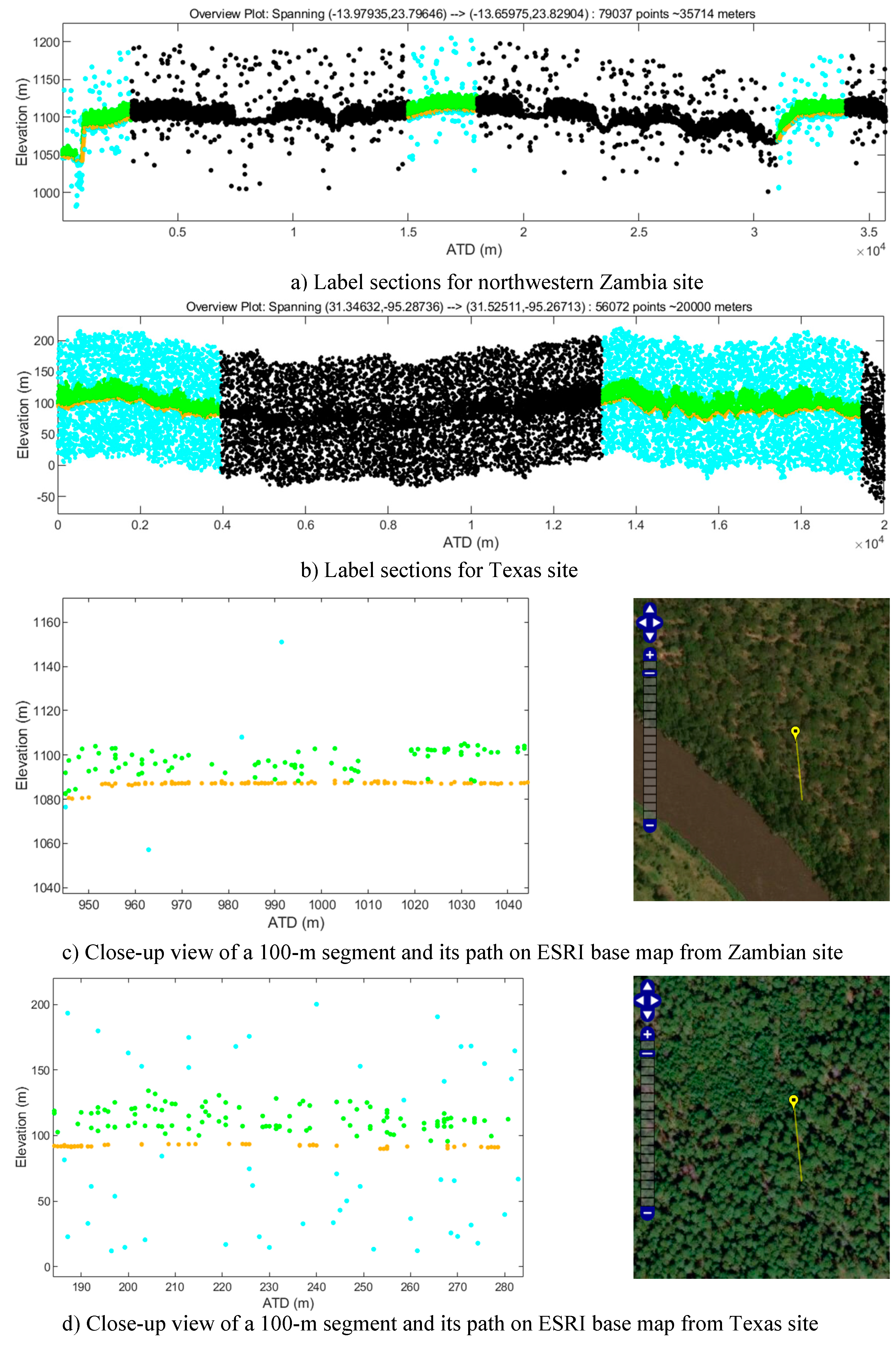
Figure 6 shows the manually labeled sections along the selected ICEsat-2 tracks and close-up views of ICESat-2 photon data over 100 m distance over the northwestern Zambia and Texas sites. The differences in the noise levels is notable reflecting the significant impact of solar background radiation can have on photon counting lidar measurements. The close-up views of the data also show differences in the amount of noise and the number of terrain points indicating differences in the level of photon canopy penetration. Table 2 summarizes the number of points labeled along selected ICESat-2 tracks for the two sites. The distribution of the three-point classes is markedly different between the two sites. The proportion of noise points in the two sites was 3.2% for Zambia and 31.1% for Texas. The ICESat-2 granule labeled for the Texas site was collected during the day (13:04:56 UTC) when the effect of background solar radiation is higher while the data used for the Zambia site was collected at night (02:53:40 UTC). The other notable difference is in the proportion of terrain and off-terrain points. About two-thirds of the points for the Zambian site were ground whereas terrain points only account for less than a fifth of the points labeled. The reverse is observed for off-terrain points with the Texas site showing a large proportion of points than the Zambian sites. Apart from the time the data was acquired, these differences a reflective of the different vegetation structure (sparse vs closed canopy) or phenological stages (leaf-on vs leaf-off) in the two sites. The data for the Zambia site was acquired in June, which is a leaf-off period for most deciduous forest in Zambia while Texas forests were in their leaf-off state at the time the data was acquired in April [21,22].

3.2. ATL08 Photon Classification Comparison Results

ATL08 photon labels were highly comparable to corresponding PhotonLabeler labels with overall accuracies of 93.3% (Table 3) and 95.4% (Table 4) for the Texas and Zambia sites, respectively. Despite the high overall accuracies of ATL08 with respect to PhotonLabeler labels for both sites, there are notable differences in for specific photon classes. For instance, higher omission errors (45.3%, Table 3) were observed for the data from the Zambia site than the Texas site (12.3%, Table 4)). On the other hand, terrain points had higher commission errors for the Texas site (26.9%, Table 4) than the Zambia site (5.2%, Table 3). These variations could be attributed to the impact of different noise levels on performance of ATL08 filtering algorithms. Going by the higher omission errors for the Zambia case, the ATL08 algorithm was more prone to misclassify noise photons for data with relatively less noise. The higher number of terrain points for the Zambia site also likely contributed to lower omission and commission errors for terrain points indicating better discrimination at the terrain-off-terrain boundary than the Texas case.
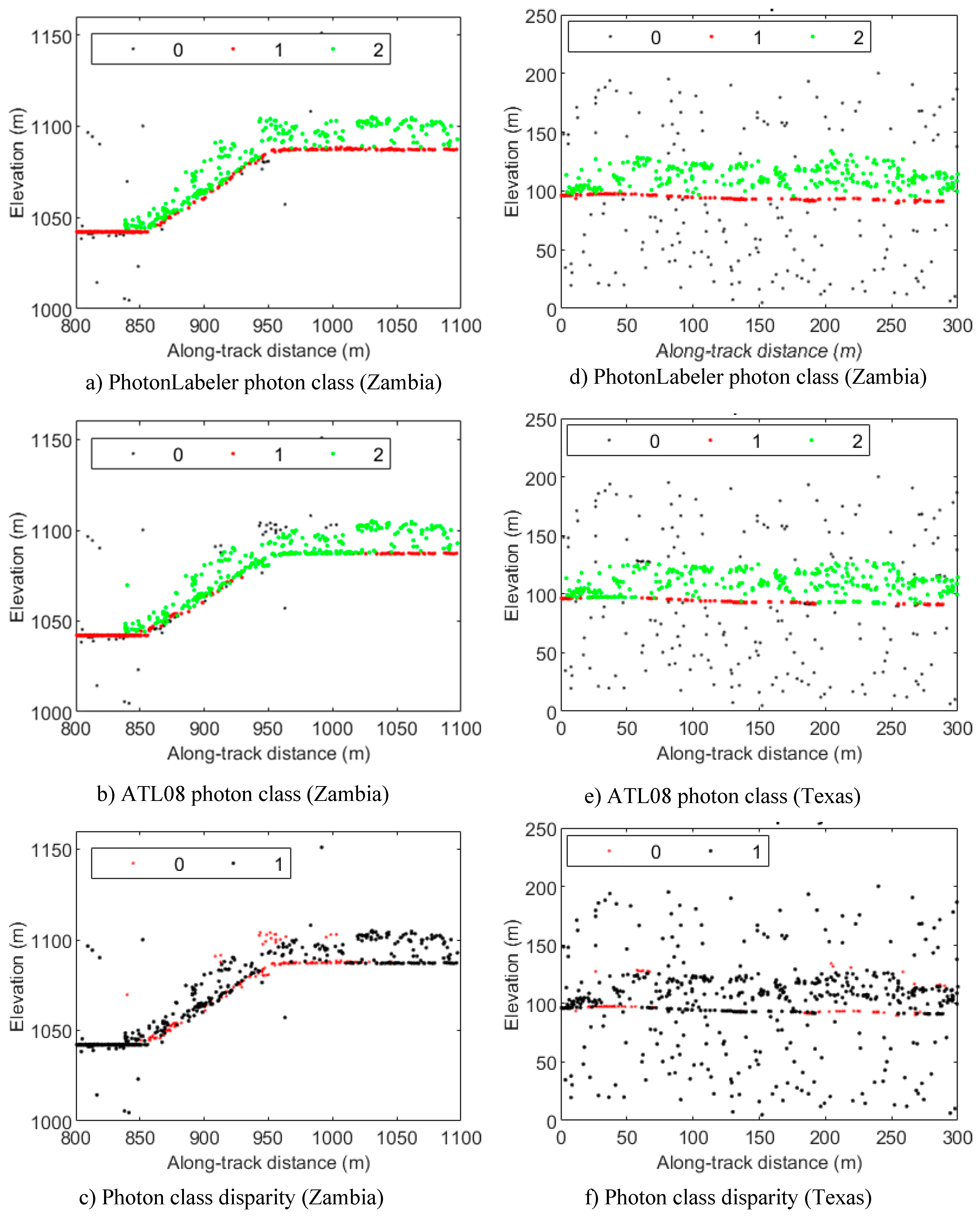
In Figure 7, we highlight some differences between PhotonLabeler and ATL08 photon classes. Differences in photon classes mainly occurred at the inter-class boundaries, e.g., terrain-Off-terrain or Off-terrain-Noise boundaries (Figure 7c,f). We also observed that the ATL08 product misclassified terrain points especially in areas of high curvature or abrupt topographic gradients (Figure 7c). Overall, these results show high consistency between PhotonLabeler and ATL08 photon classes.

3.3. ATL08 Height Metric Comparison Results

Table 5 and Table 6 summarize the relationships between various height metrics compared with corresponding estimates derived from manually labeled point data. The total numbers of ATL08 segments with valid canopy height estimates matched with labeled data from the Zambian and Texas sites were 84 and 90, respectively. The number of segments with valid terrain height estimates were 92 and 88 for the Zambian and Texas sites, respectively. In general, ATL08 height metrics were highly correlated (R2 > 0.8) with corresponding metrics from labeled data especially for absolute canopy and terrain height metrics. This was expected given the good agreement between PhotonLabeler and ATL08 photon labels. The correlation of ATL08 relative canopy heights with PhotonLabeler (PL) metrics varied by height metric with the minimum height values for the Zambia site showing a zero R2 value. We attribute the lack of correlation for minimum values to the 0.5 m threshold we applied when calculating relative height metrics, which force most of our minimum values to be 0.5 m. The maximum relative canopy values for the Texas site showed higher correlation with PL values compared to values for the Zambian site. This is somewhat surprising observation considering near-clean data for the Zambian site. The correlation for ATL08 percentile height metrics generally increased with the percentile level from P25 to P95 (R2 = 0.57–0.89 for the Texas site, R2 = 0.67–0.86 for Zambia site).
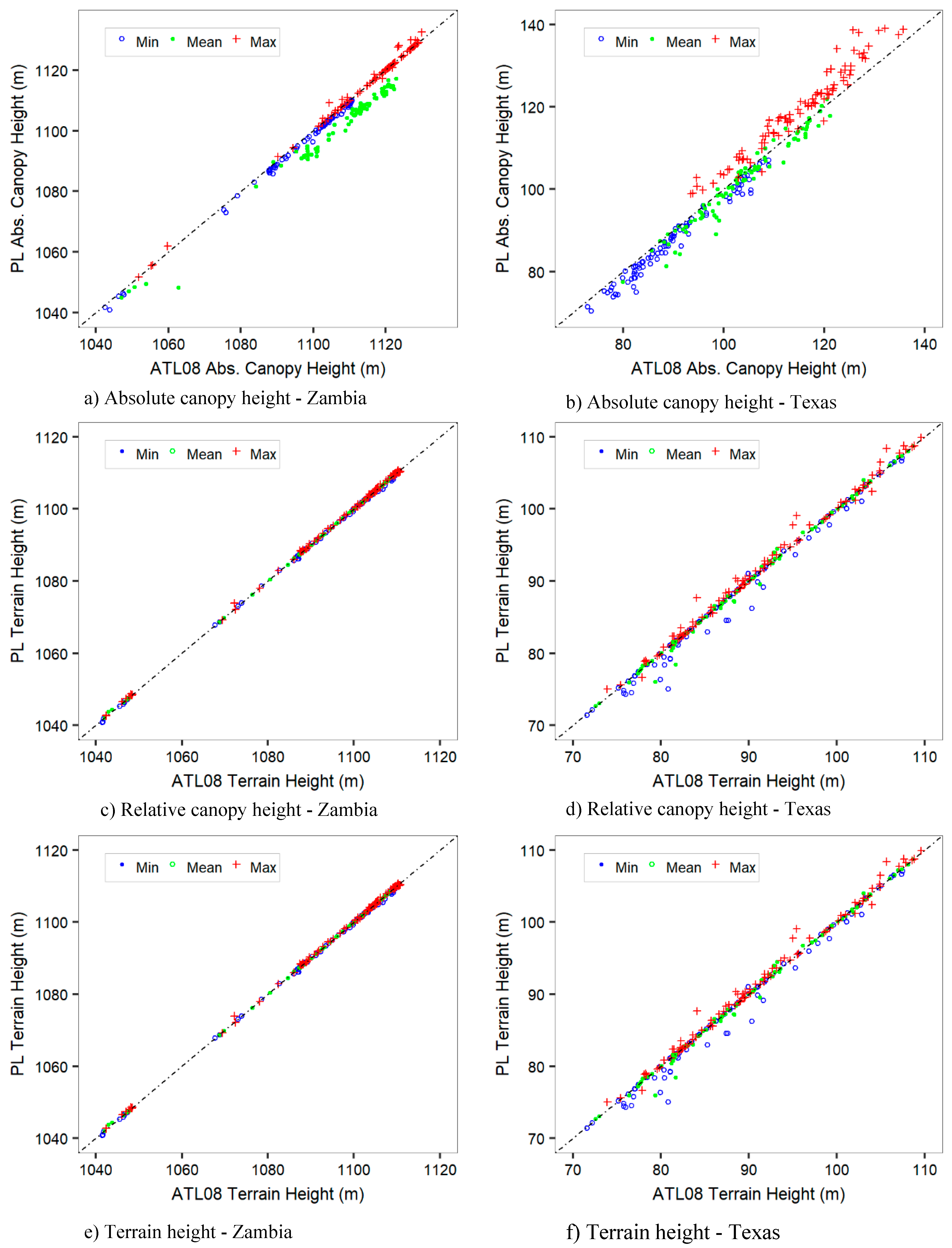
The precision (Table 6) based on calculated mean biases of ATL08 absolute canopy, relative canopy, and terrain height metrics with respect to PL metrics varied from −9.76 m (over-estimation) to 4.63 m (under-estimation). The precision between the two datasets improved with percentile level. For the Texas site, we observed over-estimation at lower percentiles (P25–P60) including the minimum and mean height, which switched to under-estimation at higher percentiles (P70–P95, Max). For the Zambia case, there was general over-estimation across all metrics except for the maximum height. Again, we expected the Zambia case to provide better results due to the lower noise levels. These variations could be attributed to the impact of different noise levels on performance of ATL08 filtering algorithms. Results for relative canopy heights were as expected with the Zambia case showing lower biases (−0.36–0.70 m) compared to the Texas case (0.48–4.63 m). Lastly, ATL08 terrain height estimates showed high precision with respect to PL metrics for both sites. Figure 8 shows graphical relationships between ATL08 absolute canopy, relative canopy, and terrain data with corresponding PL data for the minimum, mean, and maximum height metrics.

4. Discussion

Over the decades, lidar remote sensing has proven to be a highly effective technique for characterizing the 3D structure of terrestrial ecosystems including forests, snow ice and topography in general. Space-borne lidar missions such as ICESat-2 extend our capability to characterize terrestrial ecosystems from local to global scales. Critical to these endeavors are analysis methods and software tools to foster a better understanding of phenomena of interest including forest structure, bathymetry or surface topography or the understanding of the data itself. The PhotonLabeler application described in this study is an effort to provide researchers with a tool for easy visualization and labeling of ICESat-2 photon data. Such capability could support a number of analyses, including checking the accuracy of height estimates provided by ICESat-2 products as demonstrated in the case study or training new or re-calibrating existing algorithms with manually labeled data. Development of labeled photon datasets could motivate the development of even better algorithms for generating various products from ATL03 data. Machine learning and deep learning techniques present one avenue for developing robust approaches [23,24], but still lack labeled point data to motivate adoption as in image-based analyses. Using applications such as PhotonLabeler could readily support such labeled data collection tasks.
The critical importance of data visualization in remote sensing research to enhancing understanding of phenomena and communication cannot be over-emphasized. We believe software tools such as the PhotonLabeler present a great avenue to understanding ICESat-2 data in diverse environments, especially with the facility to view both point data and geo-linked high-resolution image web maps. Researchers and educators may use it as a tool for instruction to demonstrate a variety of aspects of the ICESat-2 ATL03 data including responses of photon counting lidar in various environments. For instance, the impact of solar background illumination on the data quality could be shown by displaying day and night acquisitions. The impact of canopy cover on photon penetration in environments such as the Amazon compared to sparsely forested environments in the Savannas of Southern Africa, is another example. Insight or cues on developing algorithms could also be generated from visualizing data in different ecoregions.
The case studies on the manual validation of ATL08 data provided a glimpse into the accuracy of ATL08 data for day and night acquisition. These results were generally promising with high correlations (R2 > 0.8) and precision (mean biases < 5) between ATL08 estimates and estimates generated from manually labeled data. ATL08 photon labels also matched photon labels from the PhotonLabeler very well (overall accuracies > 90%). However, these observations as the results of this assessment are limited. Further validation assessment incorporating data in various ecoregions, seasons and of different noise levels is still needed to provide a more complete view of the accuracy of the ATL08 estimates. We also acknowledged that manually labeled data is not immune to error and inconsistencies may arise between how the ATL08 algorithms define surfaces and how we manually labeled data. Given the high correlations between ATL08 and PL estimates, we think that was not a big issue for this assessment. For future studies intending to do similar assessments on a large scale, we recommended developing labeling protocols to enhance consistency among labeling experts or data in different environments.
Additional functionality in the PhotonLabeler application is in the works to enhance productivity and general user-friendliness. Given that some ICESat-2 products such as ATL06 and ATL08 also contain photon level classification data, one capability envisioned is to enable users start labeling based on the existing labels and updating them where necessary. In collecting reference data for our demonstration study, it took about 20–30 min to label a 3000-m section along an ATL03 track, which could add up for many sections of the data. Providing functionality to start labeling from some existing classification would enhance labeling efficiency from our current setup and would complement assisted labeling, such as automatic top of canopy selection, already implemented in the application. We are also working on providing wider options for saving labeled data. One option is saving the labeled data in HDF format similar to the ATL03 structure to improve the organization of the data. The other option to be included in future releases of the software is saving to industry formats such as LAS to facilitate view of the data with other software packages.

5. Conclusions

This study presented a user-friendly software application to support visualization and manual labeling of ICESat-2 ATL03 photon data. The application enables definition of custom labeling schemes to meet requirements of a research study and offers various point selection tools to facility collection of labeled data. Labeled data collected using the PhotonLabeler can serve as reference data for validating various ICESAt-2 elevation products especially in developing countries were airborne lidar acquisitions are not routinely done. We were able to demonstrate how manually labeled data could be applied for validating ATL08 estimates. Such an assessment could be extended to other validation studies for snow ice elevation or bathymetry. The PhotonLabeler can also facilitate the development of new algorithms by providing critical labeled data to support testing and validation.

Supplementary Materials

The instruction for PhotonLabeler is available in https://www.mdpi.com/2072-4292/12/19/3168/s1.

Author Contributions

Conceptualization, L.M.; Data curation, L.M.; Formal analysis, L.M.; Funding acquisition, L.M. and S.P.; Methodology, L.M.; Project administration, S.P.; Resources, S.P.; Software, L.M.; Validation, Lonesome Malambo; Writing—original draft, L.M.; Writing—review & editing, L.M. and S.P. All authors have read and agreed to the published version of the manuscript.

Funding

This research was funded NASA ICESat-2 Science Team, Studies with ICESat-2, grant number NNH19ZDA001N. The open access publishing fees for this article have been covered by the Texas A&M University Open Access to Knowledge Fund (OAKFund), supported by the University Libraries and the Office of the Vice President for Research.

Acknowledgments

This research was funded by NASA ICESat-2 Science Team, Studies with ICESat-2 NNH19ZDA001N grant.

Conflicts of Interest

The authors declare no conflict of interest.

References

  1. Markus, T.; Neumann, T.; Martino, A.; Abdalati, W.; Brunt, K.; Csatho, B.; Farrell, S.; Fricker, H.; Gardner, A.; Harding, D.; et al. The ice, cloud, and land elevation satellite-2 (ICESat-2): Science requirements, concept, and implementation. Remote Sens. Environ. 2017, 190, 260–273. [Google Scholar] [CrossRef]
  2. Popescu, S.C.; Zhou, T.; Nelson, R.; Neuenschwander, A.; Sheridan, R.; Narine, L.; Walsh, K.M. Photon counting lidar: An adaptive ground and canopy height retrieval algorithm for ICESat-2 data. Remote Sens. Environ. 2018, 208, 154–170. [Google Scholar] [CrossRef]
  3. Petty, A.A.; Kurtz, N.T.; Kwok, R.; Markus, T.; Neumann, T.A. Winter arctic sea ice thickness from ICESat-2 freeboards. J. Geophys. Res. Oceans 2020, 125, e2019JC015764. [Google Scholar] [CrossRef]
  4. Smith, B.; Fricker, H.A.; Gardner, A.S.; Medley, B.; Nilsson, J.; Paolo, F.S.; Holschuh, N.; Adusumilli, S.; Brunt, K.; Csatho, B.; et al. Pervasive ice sheet mass loss reflects competing ocean and atmosphere processes. Science 2020, 368, 1239–1242. [Google Scholar] [CrossRef] [PubMed]
  5. Neuenschwander, A.L.; Magruder, L.A. Canopy and terrain height retrievals with ICESat-2: A first look. Remote Sens. Basel 2019, 11, 1721. [Google Scholar] [CrossRef] [Green Version]
  6. Narine, L.L.; Popescu, S.C.; Malambo, L. Using ICESat-2 to estimate and map forest aboveground biomass: A first example. Remote Sens. Basel 2020, 12, 1824. [Google Scholar] [CrossRef]
  7. Zhang, G.; Chen, W.; Xie, H. Tibetan plateau’s lake level and volume changes from NASA’s ICESat/ICESat-2 and Landsat missions. Geophys. Res. Lett. 2019, 46, 13107–13118. [Google Scholar] [CrossRef]
  8. Harding, D.J.; Dabney, P.W.; Valett, S. Polarimetric, Two-Color, Photon-Counting Laser Altimeter Measurements of Forest Canopy Structure; International Symposium on Lidar and Radar Mapping 2011: Technologies and Applications, 2011; International Society for Optics and Photonics: Bellingham, WA, USA, 2011; p. 828629. [Google Scholar]
  9. Neumann, T.; Brenner, A.; Hancock, D.; Robbins, J.; Saba, J.; Harbeck, K.; Gibbons, A. Ice, Cloud, and Land Elevation Satellite–2 (ICESat-2) Project: Algorithm Theoretical Basis Document (ATBD) for Global Geolocated Photons (ATL03); National Aeronautics and Space Administration, Goddard Space Flight Center: Greenbelt, MD, USA, 2019. Available online: https://escholarship.org/uc/item/0xv7b6br#main (accessed on 24 September 2020).
  10. Swatantran, A.; Tang, H.; Barrett, T.; DeCola, P.; Dubayah, R. Rapid, high-resolution forest structure and terrain mapping over large areas using single photon lidar. Sci. Rep. UK 2016, 6, 28277. [Google Scholar] [CrossRef] [PubMed] [Green Version]
  11. Parrish, C.E.; Magruder, L.A.; Neuenschwander, A.L.; Forfinski-Sarkozi, N.; Alonzo, M.; Jasinski, M. Validation of ICESat-2 ATLAS bathymetry and analysis of atlas’s bathymetric mapping performance. Remote Sens. Basel 2019, 11, 1634. [Google Scholar] [CrossRef] [Green Version]
  12. Wang, C.; Zhu, X.; Nie, S.; Xi, X.; Li, D.; Zheng, W.; Chen, S. Ground elevation accuracy verification of ICESat-2 data: A case study in Alaska, USA. Opt. Express 2019, 27, 38168–38179. [Google Scholar] [CrossRef] [PubMed]
  13. Malambo, L.; Heatwole, C.D. Automated training sample definition for seasonal burned area mapping. ISPRS J. Photogramm. Remote Sens. 2020, 160, 107–123. [Google Scholar] [CrossRef]
  14. Kennedy, R.E.; Cohen, W.B.; Schroeder, T.A. Trajectory-based change detection for automated characterization of forest disturbance dynamics. Remote Sens. Environ. 2007, 110, 370–386. [Google Scholar] [CrossRef]
  15. Malambo, L.; Popescu, S.C.; Horne, D.W.; Pugh, N.A.; Rooney, W.L. Automated detection and measurement of individual sorghum panicles using density-based clustering of terrestrial lidar data. ISPRS J. Photogramm. Remote Sens. 2019, 149, 1–13. [Google Scholar] [CrossRef]
  16. Neuenschwander, A.; Popescu, S.; Nelson, R.; Harding, D.; Pitts, K.; Robbins, J.; Pederson, D.; Sheridan, R. Ice, Cloud, and Land Elevation 1 Satellite 2 (ICESat-2) Algorithm Theoretical Basis Document (ATBD) for Land-Vegetation Along-Track Products (ATL08) Release 002; National Aeronautics and Space Administration, Goddard Space Flight Centre: Greenbelt, MD, USA, 2019. Available online: https://icesat-2.gsfc.nasa.gov/sites/default/files/page_files/ICESat2_ATL08_ATBD_r002_v2.pdf (accessed on 24 September 2020).
  17. Neuenschwander, A.; Pitts, K. The ATL08 land and vegetation product for the ICESat-2 mission. Remote Sens. Environ. 2019, 221, 247–259. [Google Scholar] [CrossRef]
  18. Hansen, M.C.; Potapov, P.V.; Goetz, S.J.; Turubanova, S.; Tyukavina, A.; Krylov, A.; Kommareddy, A.; Egorov, A. Mapping tree height distributions in sub-saharan Africa using Landsat 7 and 8 data. Remote Sens. Environ. 2016, 185, 221–232. [Google Scholar] [CrossRef] [Green Version]
  19. Liu, C.; Neal, J.; Scofield, C.; Chang, J.; Ludeke, A.K.; Frentress, C. Classification of Land Cover and Assessment of Forested Wetlands in the Cypress Creek Watershed; Texas Parks and Wildlife Department: Austin, TX, USA, 1996; 21p.
  20. Isenburg, M. Lastools: Efficient Tools for Lidar Processing. Available online: https://rapidlasso.com/lastools/ (accessed on 15 January 2020).
  21. Chidumayo, E. Climate and phenology of savanna vegetation in southern Africa. J. Veg. Sci. 2001, 347–354. [Google Scholar] [CrossRef]
  22. Hill, M.J.; Millington, A.; Lemons, R.; New, C. Functional phenology of a Texas post oak savanna from a chris proba time series. Remote Sens. Basel 2019, 11, 2388. [Google Scholar] [CrossRef] [Green Version]
  23. Malambo, L.; Popescu, S.; Ku, N.-W.; Rooney, W.; Zhou, T.; Moore, S. A deep learning semantic segmentation-based approach for field-level sorghum panicle counting. Remote Sens. Basel 2019, 11, 2939. [Google Scholar] [CrossRef] [Green Version]
  24. Narine, L.L.; Popescu, S.C.; Malambo, L. Synergy of ICESat-2 and Landsat for mapping forest aboveground biomass with deep learning. Remote Sens. Basel 2019, 11, 1503. [Google Scholar] [CrossRef]
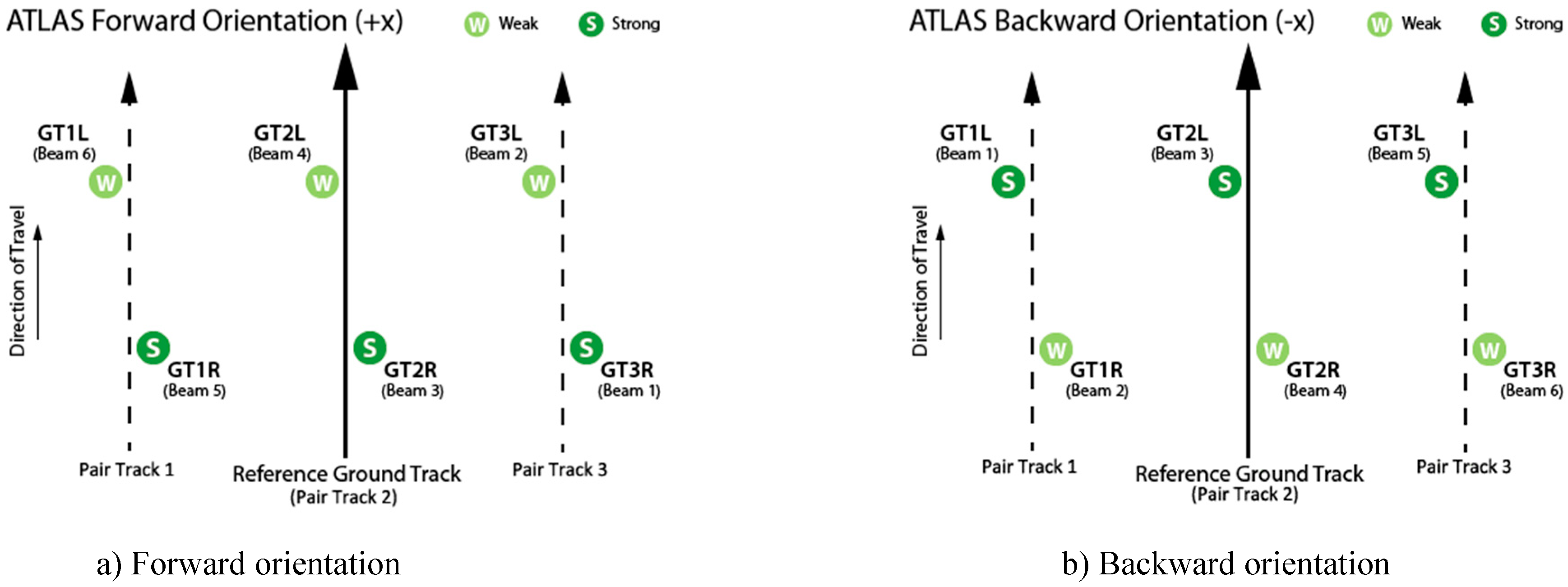
Figure 1. Ground track (GT) naming convention: (a) Advanced Topographic Laser Altimeter System (ATLAS) oriented in the forward (instrument coordinate +x) direction, (b) ATLAS oriented in the backward (instrument coordinate +x) direction. Image credit: ICESat-2 Project Team [9].
Remotesensing 12 03168 g001
Figure 2. Interpretation of ATL03 data. Observing point distribution differences is useful in interpreting noise (random) and signal (clustered) points: (a) Sample ATL03 data with lower noise levels over a site in north-western Zambia; (b) Sample ATL03 data with higher noise level over a site in eastern Texas, United States; (a,b) also show further classification of signal points into terrain (lower local elevation variation) and vegetation (above terrain and exhibit higher local elevation variation); (c) Sample ATL03 data corrupted by instrument errors, which could be interpreted as noise. (d) Samples data with cloud points, which are identifiable by their significant elevation values compared to terrain points; (e) Interpretation of ATL03 data over a built area in Houston, Texas. Shape attributes and regularity of surface is key to differentiating them from terrain; (f) Using ancillary image data to aid interpretation of data in (e). ATD is along-track distance.
Remotesensing 12 03168 g002
Figure 3. Web map integration. The section of an ICESat-2 track under consideration is displayed on a web-based map to aid interpretation of the ATL03 data.
Remotesensing 12 03168 g003
Figure 4. PhotonLabeler graphical user interface showing track and label information and tools on the left panel, plot areas in middle and data display control and labeling and navigation tools on the right panel.
Remotesensing 12 03168 g004
Figure 5. Label definition tools in the PhotonLabeler. The red arrow illustrates the process of defining a new point label.
Remotesensing 12 03168 g005
Figure 6. Manual Photon Labeling using the Photon Labeler. (a,b) Label sections along ICESat-2 tracks for the Zambian and Texas sites; (c,d) Close-up plot and base map views of 100-m segments for the Zambia and Texas sites.
Remotesensing 12 03168 g006
Figure 7. Comparison of PhotonLabeler and ATL08 photon label data for the Zambia and Texas sites over 300 m distance: (a) ATL03 data for Zambia site with photon labels from PhotonLabeler (0 = Noise, 1 = Terrain, 2 = Off-terrain), (b) ATL03 data for Zambia site with photon labels from ATL08 product (0 = Noise, 1 = Terrain, 2 = Off-terrain), (c) Photon class disparity for the Zambia site showing regions of disagreement (0,red) and areas of agreement (1, black). (d) ATL03 data for Texas site with photon labels from PhotonLabeler (0 = Noise, 1 = Terrain, 2 = Off-terrain), (e) ATL03 data for Texas site with photon labels from ATL08 product (0 = Noise, 1 = Terrain, 2 = Off-terrain), (f) Photon class disparity for the Texas site showing regions of disagreement (0, red) and areas of agreement (1, black).
Remotesensing 12 03168 g007
Figure 8. Relationships between ATL08 minimum (Min), mean (Mean), and maximum (Max) height estimates and matching height estimates from PhotonLabeler (PL) labeled data for the Zambian (first column) and Texas (second column) sites: (a,b) Absolute canopy heights; (c,d) Relative canopy heights; (e,f) Terrain heights. The dashed line shows the expected 1:1 relationship between PL and ATL08 estimates.
Remotesensing 12 03168 g008
Table 1. ATL08 height metrics evaluated for the study. Height metrics include the minimum (Min), mean (Mean), maximum (Max), and height percentiles (Pxx, e.g., P25 for 25th percentile height). Metrics evaluated for a particular height type (Absolute canopy, Relative canopy, and Terrain height) are marked by x.
MetricMaxMeanMinP25P50P60P70P75P80P85P90P95
Absolute canopy heightxxxxxxxxxxxx
Relative canopy heightxxxxxxxxxxxx
Terrain heightxxx
Table 2. Number of manually labeled points in northwestern Zambia and Texas.
Northwestern ZambiaEastern Texas, USA
LabelLabel CodeNo. PointsProportion (%)No. PointsProportion (%)
Noise06953.2735531.1
Terrain113,84363.7330614.0
Off-terrain2720133.113,02655.0
Total 21,73910023,687100.0
Table 3. Confusion matrix between PhotonLabeler and ATL08 photon labels for the Zambia site. Overall accuracy 95.4%.
PhotonLabelerError (%)
LabelsNoiseTerrainOff-TerrainTotalCommissionOmission
ATL08Noise3802294117.545.3
Terrain21513,69353114,4395.21.1
Off-terrain100128666168893.37.5
Total69513,843720121,739
Table 4. Confusion matrix between PhotonLabeler and ATL08 photon labels for the Texas site. Overall accuracy 95.4%.
PhotonLabeler Error (%)
LabelsNoiseTerrainOff-TerrainTotalCommissionOmission
ATL08Noise645008365331.312.3
Terrain6443248549444126.91.8
Off-terrain2615812,39412,7132.54.9
Total7355330613,02623,687
Table 5. Correlation (R2) between ATL08 absolute canopy, relative canopy, and terrain height metrics with metrics derived from manually labeled point data for the Zambia and Texas sites. Height metrics include the minimum (Min), mean (Mean), maximum (Max), and percentiles (Pxx, e.g., P25 for 25th percentile height).
Absolute Canopy HeightRelative Canopy HeightTerrain Height
MetricTexasZambiaTexasZambiaTexasZambia
Max0.941.000.820.600.991.00
Mean0.960.990.820.821.001.00
Min0.981.000.290.000.991.00
P250.870.980.570.67
P500.890.950.620.86
P600.900.940.710.79
P700.940.920.750.73
P750.960.930.790.78
P800.970.950.850.78
P850.980.970.840.79
P900.970.990.870.80
P950.970.990.890.76
Table 6. Precision (mean biases) between ATL08 absolute canopy, relative canopy and terrain height metrics with metrics derived from manually labeled point data for the Zambia and Texas sites. Height metrics include the minimum (Min), mean (Mean), maximum (Max), and percentiles (Pxx, e.g., P25 for 25th percentile height).
Absolute Canopy HeightRelative Canopy HeightTerrain Height
MetricTexasZambiaTexasZambiaTexasZambia
Max4.290.354.63−0.170.450.19
Mean−1.51−5.892.910.26−0.080.02
Min−2.39−1.310.480.18−0.61−0.21
P25−5.13−6.363.140.70
P50−1.76−9.633.270.14
P60−0.61−9.763.160.03
P700.39−7.893.00−0.02
P750.90−6.443.00−0.10
P801.47−4.933.02−0.25
P851.83−3.313.12−0.33
P902.33−2.143.19−0.36
P952.69−1.333.36−0.34