Abstract
The detection of gas plumes from multibeam water column (MWC) data is the most direct way to discover gas hydrate reservoirs, but current methods often have low reliability, leading to inefficient detections. Therefore, this paper proposes an automatic method for gas plume detection and segmentation by analyzing the characteristics of gas plumes in MWC images. This method is based on the AdaBoost cascade classifier, combining the Haar-like feature and Local Binary Patterns (LBP) feature. After obtaining the detected result from the above algorithm, a target localization algorithm, based on a histogram similarity calculation, is given to exactly localize the detected target boxes, by considering the differences in gas plume and background noise in the backscatter strength. On this basis, a real-time segmentation method is put forward to get the size of the detected gas plumes, by integration of the image intersection and subtraction operation. Through the shallow-water and deep-water experiment verification, the detection accuracy of this method reaches 95.8%, the precision reaches 99.35% and the recall rate reaches 82.7%. Integrated with principles and experiments, the performance of the proposed method is analyzed and discussed, and finally some conclusions are drawn.
1. Introduction
Multibeam water column (MWC) data is the product of multibeam echo sounders (MBESs) [1,2]. Some MBESs, such as the Kongsberg EM series, ATLAS HYDROSWEEP, Teledyne RESON 7k series, etc., have the functions to record the original echo sequence of each beam and form the MWC data or MWC images (Figure 1). MBES is mainly used for the detection and characterization of the seabed, such as finding large pockmarks [3], surveying topography [4,5], monitoring the dynamic changes of seabed sediments [6,7] and so on. The MWC images derived from MBES are not only playing an important role in the fields of wreck detection [8,9], suspended targets detection and localization [10] and fish detection [11], but are also often used in the detection of gas bubbles [12,13].
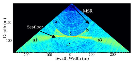
Figure 1.
A multibeam water column (MWC) image was generated by self-developed software: a and b depict the side-lobe effect and the Minimum Slant Range (MSR), respectively; c denotes a gas plume; and s1–3 are the three sectors of the ping fan image, respectively.
Natural gas hydrate is a kind of important green energy. Gas plumes formed by the leakage of gas hydrate beneath the seabed are the most direct evidence to discover the gas hydrate reservoir. Nikolovska et al. [14] discovered the gas plumes in the eastern Black Sea with the EM710 MWC data. Gardner et al. [15] found a gas plume up to 1400 m near the northern coast of California with EM302. Weber et al. [16] found a 1100 m-high gas plume in the Gulf of Mexico by EM302 MWC data. Philip et al. [17] used MWC images to study the temporal and spatial variation of a known gas-leaking area. These studies suggest that using MWC images is an effective way to detect gas plumes.
Nowadays, the gas plumes are mainly recognized from the MWC images through manually browsing these images by characteristics such as echo intensities, sizes and shapes of the gas plumes [18]. The manual recognition is simple, but time consuming and inefficient, especially for a long voyage MBES measurement. Besides, the diversity of manual recognition will become more apparent when the detected MWC image is synthetically polluted by noise from the MBES emission mode, the side-lobe effect, the particles and bio-distribution in water, etc.
To improve the detection efficiency, some scholars and companies have studied the automatic detection method based on the intensity threshold or the echo intensity difference between the target and the noise. Quality Positioning Services Inc. (QPS) has applied the threshold detection in the FMMidwater module of Fledermause software [19]. CARIS developed the modules of MWC data processing and target detection in HIPS 7.1.1 software [20]. Veloso et al. [21] used threshold filtering, speckle noise removal and manual editing in a 3D space to clean MWC images and segment targets from the filtered MWC images. Urban et al. used the image mask technique to remove the static artefacts and the threshold filtering to weaken the background noise, which improved the quality of the MWC images and detected gas plumes; however, the approximately flat seabed topography required in the filtering and the assumption of a homogeneous MWC environment in 1000 pings limit the applications of the filtering algorithm [22]. In the literature [23], the gas plume detection consists of separating the gas plume from the noise in an MWC image; but, the parameters involved in the segmentation are determined in a combined manner by the mean and standard deviation of the backscatter strengths (BSs) of a sector, and they are different for shallow-water and deep-water MWC images. These studies have achieved the automatic detection of gas plumes from MWC images, but the detection accuracy is relatively low due to various water environments and the inaccurate threshold used in the detection. Since MWC images are usually polluted by the comprehensive noise from MBES, interference of sound waves, marine environment and other factors, it is difficult to detect the gas plumes from the MWC images by the several given thresholds. To detect gas plumes in various water environments, it becomes unavoidable to frequently set these thresholds. In addition, the threshold method becomes impossible when the gas plumes lie outside the MSR, seriously polluted by the interaction of the side lobe and seabed echoes (Figure 1). Therefore, the detection of a gas plume is only performed within the MSR in the existing studies.
Nowadays, as a kind of classical target detection method, feature-based machine learning has been applied by many scholars to detect targets in sonar images. Jason Rhinelande et al. proposed a combination of feature extraction, edge filter, median filter and support vector machine to achieve target detection in side-scan sonar images [24]. Yang et al. studied an object recognition method on side-scan sonar images based on a grayscale histogram and geometric features [25]. Isaacs achieved object detection using an in situ weighted highlight-shadow detector, and performed a recognition process using an Ada-boosted decision tree classifier for underwater unexploded ordnance detection on simulated real aperture sonar data [26]. Feature selection is one of the most important steps in these machine learning algorithms, and Haar-like and Local Binary Patterns (LBP) are classical and common features in target detection [27,28,29,30,31]. On the whole, there are few studies on target detection in MWC images using features and classifiers. However, the feature-based machine learning algorithms that are pre-trained are able to detect targets in consecutive image frames quickly, in real-time and automatically, and play an important role in detecting gas plumes in MWC images.
To efficiently detect and segment gas plumes from MWC images, this paper proposes an automatic detection and segmentation method. Differing from the existing methods, the proposed method can not only accurately detect gas plumes in various water environments, including the gas plume outside the MSR, but also automatically segment the detected gas plumes. This paper is organized as follows: Section 2 details the proposed automatic detection and segmentation algorithm, including the automatic detection by the AdaBoost cascade classifier combining the Haar-like feature and LBP feature (Haar–LBP detector); the localization based on histogram similarity calculation and the segmentation based on image intersection and subtraction operation; Section 3 verifies the proposed method by the shallow-water and deep-water experiments; Section 4 discusses the performance of the proposed method; and some conclusions are drawn in Section 5 finally.
2. Automatic Detection and Segmentation Algorithm
Decoding MWC data according to the datagram format [32], an MWC image can be displayed as the depth-across track image (Figure 1) by transferring the backscatter intensities into 0–255 gray levels. As can be seen from Figure 1, the gas plume made up of gas bubbles is different from the surrounding seawater in the following features:
- Intensity features: the gas plume has higher intensities than its surrounding seawater.
- Geometric features: the gas plume has a certain height and is almost perpendicular to the seabed.
- Texture features: the texture features of the gas plume are richer than its surrounding seawater.
Based on these features, an automatic method for the gas plumes detection and segmentation from MWC data is proposed, which is shown in Figure 2. First, an automatic detection algorithm based on the Haar–LBP detector is used to find the gas plumes. Then, the exact locations of the target boxes are determined by histogram similarity calculation. Finally, the targets are segmented from the target boxes by the background differential segmentation algorithm.
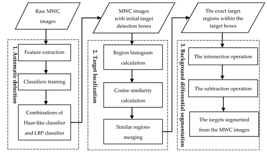
Figure 2.
Automatic gas plumes detection and segmentation method.
2.1. Automatic Detection
2.1.1. Feature Selection
Gas plumes differ from their surrounding seawater in grey, geometric and texture features. The Haar-like feature is often used to describe the geometric structure and grey-level changes of targets, and the LBP feature is a classical operator for describing local texture features of images. This paper put forwards the Haar–LBP detection algorithm, which utilizes the Haar-like feature and LBP feature to describe the gas plumes in MWC images, so that the appearance of a gas plume can be better captured while combining both the grey-level change and the texture information.
- Rectangular Haar-like Feature
A Haar-like feature is a common digital image feature used in target detection, named after its similarity to Haar wavelets. Historically, working with only image intensities made the task of feature calculation computationally expensive. A publication by Papageorgiou et al. [33] discussed working with an alternative feature set based on Haar wavelets instead of the usual image intensities. Then, Viola and Jones [34,35] developed the Haar-like features and utilized them in face detection, getting high performance and detection rates. Then Lienhart et al. further extended the Haar-like rectangular feature library [27]. The expanded feature prototypes are roughly classified into three types: four edge features, eight line features and two center-surround features, as shown in Figure 3.
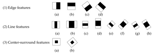
Figure 3.
Feature prototypes of edge features, line features and center-surround features. The black and white areas respectively stand for negative and positive weights.
The Haar-like feature is computed in this way: The sum of the pixels that lie within the white rectangles is subtracted from the sum of the pixels in the black rectangles [35]. For example, a three-rectangle feature computes the sum within two outside rectangles, subtracted from the sum in a center rectangle. Within the scope of the detection window, the size and position of these feature prototypes can be arbitrarily selected to obtain a feature prototype that characterizes the best classification ability. Therefore, the rectangular feature values are functions of three factors: rectangular template category, rectangular position and rectangle size. The rectangular feature value is a concrete numerical representation of the feature prototype, which is defined as follows:
In (1), N is set as 2 or 3, which means that the feature prototype has two or three rectangles. The feature prototype is located at ri = (x, y, w, h, θ). RecSum(ri) represents the sum of the pixel values in the ith rectangular area with the starting location at (x, y), the length w, width h and inclination θ. wi denotes the weight value of ith rectangular area.
Haar-like features consider adjacent rectangular regions at a specific location in a detection window, sum up the pixel intensities in each region and calculate the difference between these sums. This difference is then used to categorize the subsections of an image. Therefore, they can reflect the changes in the grey level and the structure of the specific direction well, such as the presence of edges, bars and other simple image structures [34]. Similarly, it can also quantify the characteristic differences between the gas plume and its neighbor, and thus suits the gas plumes detection in MWC images well (Figure 4).
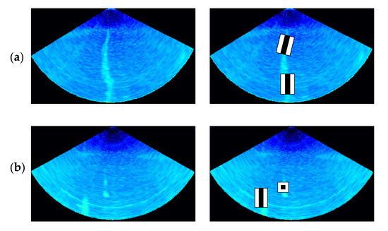
Figure 4.
Haar-like feature extraction from an MWC image. (a) The line feature is more exact to describe the grey-level changes of the vertical and inclined gas plumes. (b) For gas plumes with scatter distributions, the line feature and the center-surround feature can be used for effective description.
From Equation (1), the eigenvalues of any feature prototype at any position in the window can be calculated. Because the number of training samples and the number of rectangular features of each sample are very large, they will greatly decrease the speed of training and detection during calculation of the sum. In order to shorten the calculation time, the concept of integral images [35] is introduced in this paper.
where is the integral image and is the grey value at pixel . Taking the edge feature fb (Figure 3(1)(b)) as an example, the eigenvalue calculation is shown in Figure 5.
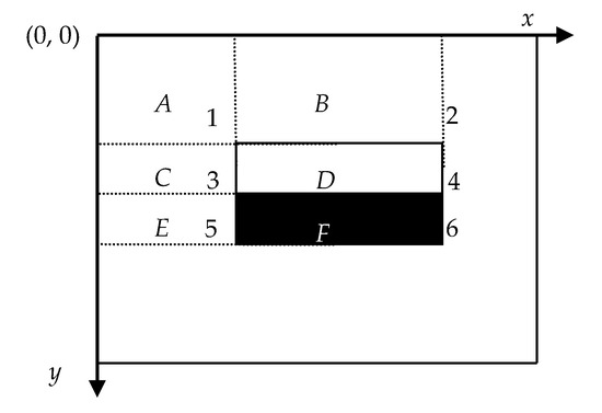
Figure 5.
Example calculation of an arbitrarily sized upright Haar-like feature.
In Figure 5, are the values at Location 1–6 in the integral image, respectively. is the sum of the pixels in rectangle A, is computed as A + B. Similarly, is A + C, and is A + B + C + D. The sum within rectangle D can be computed as .
The values of the Haar-like feature are only related to the pixels in the integral image that correspond to the corners of the rectangle in the input image (Figure 5). No matter what the size of the rectangle is, the sum of the pixels in any rectangle can be quickly calculated by searching the integral image four times. Therefore, the sum of the pixels within rectangles of arbitrary size can be calculated in a fixed time, which greatly improves the speed of calculation.
- 2.
- LBP Feature
A Haar-like feature focuses on detecting targets with a specific direction structure and obvious grey changes. A gas plume has different texture features from the water. Therefore, LBP, as a classical texture feature, is introduced to describe the texture feature of the gas plume.
LBP [36] is an operator used to describe the local texture features of an image. LBP is highly discriminative and its significant advantages, namely its invariance to monotonic grey-level changes and computational efficiency, can effectively reduce the effect of uneven grey-level changes. Due to the problem of the absorption loss of beams transmitted in water, the average grey levels of gas plumes at different depths of MWC images are different. The LBP operator is defined by comparing the central rectangle’s average intensity with those of its neighborhood rectangles, which can more effectively eliminate the effect of the absorption loss on the uneven grey level change of the image target. Generally, LBP features can effectively describe the texture characteristics of gas plumes at different depths, and thus the grey level invariance of LBP has good robustness in gas plume detection.
The steps of LBP feature vector extraction from an MWC image are as follows:
Step 1: The detection window is divided into 16 × 16 cells;
Step 2: For one pixel of each cell, if its pixel value is lower than the central pixel in the 3 × 3 region, its position is marked as 0, otherwise as 1. By this way, 8 pixels can generate an 8-bit binary number, which is used as the LBP value of the center pixel to reflect the texture information of the 3 × 3 region (Figure 6);

Figure 6.
The Local Binary Patterns (LBP) value of the 3 × 3 region.
Step 3: With the determined binary numbers, the histogram for each cell (the frequency of LBP value) is calculated and normalized;
Step 4: The statistical histograms of the LBP patterns from different cells are concatenated into a feature vector to describe the texture of the current scanning window.
2.1.2. Construction of Classification Model
After getting the Haar-like and LBP features set, an algorithm is needed for training the feature set and getting a classifier as well as the classification model for detecting the gas plumes. AdaBoost (Figure 7) is an iterative algorithm and suitable for the training.

Figure 7.
Construction of a classification model by the AdaBoost algorithm. ai (i = 1, 2, …T) is the weight of the hith classifier, and x is an input vector.
The algorithm aims to obtain a series of weak classifiers for the same training set through autonomous learning, and select a small number of critical features from a very large set of potential features. During the training, the weights of the falsely classified samples are increased, while the correct ones are reduced to enhance the attention to the previous falsely classified samples in the next training. Finally, based on some certain rules, these weak classifiers are applied to construct a strong classifier for classifying the interested targets. The algorithm can exclude some unnecessary training data, while paying more attention to the key ones.
x is defined as the feature set and y as the label, setting y = 0 for negative samples and y = 1 for positive samples. Given training samples , here n is the number of samples. The training process by AdaBoost is depicted as follows [37]:
Step 1: Initialize the weights,
where ,
Step 2: Calculate the weak classifier corresponding to each feature f and weighted error rate ,
Step 3: Choose a weak classifier with minimum error rate,
Calculate the minimum classification error rate ε, and according to the principle of minimum error rate, the threshold θ and polarity p of the weak classifier are determined.
Step 4: Update the weights by
When samples are classified correctly, . Otherwise, .
Step 5: Generate a strong classifier by combining T optimal weak classifiers,
In the detection phase, a window of the target size is moved over the input image, and for each subsection of the image, Haar-like and LBP features are calculated. The classifier gives an evaluation value C(x) to determine whether it is a gas plume according to the weight of the feature value. If the weight is 1, there exists a gas plume in the detected sample. Otherwise, there are no gas plumes.
2.1.3. Target Detection Based on the Haar–LBP Detector
Haar-like feature can reflect the grey-level changes of an image and describe the structure of the specific direction well; but, the target detection based on Haar-like features needs a large number of features to achieve a high correct detection rate, and is time-consuming in training. The detection by the LBP feature is faster and more efficient than that of the Haar-like feature, and can reflect texture features, but its accuracy depends on the training set. In order to overcome the limitations of single feature detection and improve the robustness of gas plumes detection in a complex seawater environment, a comprehensive detection algorithm, namely, detection based on the Haar–LBP detector, is put forward and depicted as Figure 8.

Figure 8.
The framework of the Haar–LBP detector.
For both the Haar-like features and LBP features, the cascade classifiers are trained by the AdaBoost algorithm. Then, the Haar-like classifier and LBP classifier are used to detect the region, respectively. The Haar-like classifier focuses on detecting some targets with a specific direction structure and obvious grey changes, while the LBP classifier focuses on detecting targets with obvious local texture features. To get accurate detection results, the following measures are given to merge the candidate bounding boxes detected by the two classifiers.
Step 1: Calculate the similarity of the detection boxes. If the position differences between the four vertices of the two detection boxes are less than the threshold δ, it means that they are similar rectangles, where δ is obtained by multiplying the sum of the minimum length and width of the two detection boxes by a certain coefficient.
Step 2: Classify the detection boxes. The similar rectangles are classified into one class. The categories with a small number of rectangular boxes and low comprehensive scores are deleted, and the small detection boxes embedded inside the large detection boxes are also deleted.
Step 3: Merge candidate bounding boxes. Calculate the average position of detection boxes for each category to generate only one detection box by clustering.
2.1.4. Evaluation of Performance Evaluation
For classifiers or classification algorithms, the most persuasive and versatile performance evaluation mainly includes Receiver Operating Characteristic (ROC), Area under the Curve (AUC), Precision-Recall curve (PRC) and so on. The ROC curve and AUC are often used to evaluate a binary classifier. It mainly shows a trade-off between true positive rate (TPR) and false positive rate (FPR). The ROC curve takes the evaluation of positive and negative examples into account, and it can objectively identify a better classifier even if the proportion of positive and negative samples is imbalanced. PRC is more focused on positive examples. It takes recall (TPR) as the abscissa axis like ROC and precision as the ordinate axis. PRC is sensitive to the sample proportion, so it can show the performance of the classifier as the sample proportion changes. Since the actual data is imbalanced, PRC helps to understand the actual effect and function of the classifier [38].
where TP and TN are true positives and true negatives; FP and FN are false positives and false negatives.
2.2. Target Localization
By the Haar–LBP detector, approximate locations of the detected target box are obtained. To detect the targets exactly in real time, this paper proposes the target localization algorithm based on histogram similarity calculation. Generally, gas plumes have higher BSs than the noise in MWC data [23], hence their grey histogram distributions in MWC images are quite different, especially in the high greyscale range. The proposed algorithm utilizes the information in a high greyscale range of the grey histogram to calculate the similarities between the target-box regions and their neighboring regions. Then, the most similar regions are iteratively grouped together, and the exact target-box locations are obtained by connecting their boundaries. Figure 9 provides a pictorial summary of the proposed algorithm, showing the image region extraction, the vector of histogram generation and similarity calculation.
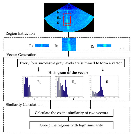
Figure 9.
An overview of the target localization algorithm.
The localization process is detailed as follows.
Step 1: Obtain initial regions R = {r1, r2, …,rn} near the detected region r0;
Step 2: For each neighboring region pair (r0, ri):
1. Obtain the grey histogram of each region;
2. Divide the grey histogram into 64 parts, each composed of 4 successive grey levels;
3. Calculate the sum of the 4 values in the parts of histogram whose grey levels are between 144 and 255, since the information of the high grey levels in the histogram is more concerning, and the 28 numbers obtained from a vector (fingerprint) of the region;
4. Convert the region pair (r0, ri) into two vectors as A and B according to Steps (1), (2) and (3);
5. Calculate the similarity of two vectors S0 i by using the Pearson Correlation Coefficient or cosine similarity. Cosine similarity is chosen here:
where Ai and Bi represent the components of vector A and B, respectively, which are the sum of the 4 values of each part.
Step 3: For i = 1, 2, …, N, compare S0 i and T until S0 i < T, and merge r0 and r1, r2, …, ri-1 to get the accurate range of the target localization.
2.3. Background Differential Segmentation
The algorithm mentioned above is able to detect and locate the target quickly and correctly. In order to measure the size of the target, it is necessary to segment the target. Due to the complexity of the underwater environment, MWC images are often seriously polluted by various environmental noises. To get the true shape of the detected gas plume, a real-time segmentation method based on an image intersection and subtraction operation is proposed in this paper. In the algorithm, the background noise in the target boxes is estimated by the intersection operation, and then is removed by subtracting it from the detected target boxes in the MWC images.
Some MBESs, such as Kongsberg EM 304 and 710, employ the multi-sector and dual-swath technique to reduce external interferences with the different emission frequencies in different sectors and adjacent pings [10]. Due to the frequency differences, the interferences appear in not only the sectors (Figure 1) but also two adjacent pings (Figure 10b), which are called background noises here.
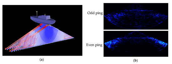
Figure 10.
(a) Denotes the dual-swath emissions, and (b) shows the background noise of odd and even pings.
Based on the above emission modes and characteristics of noise in the MWC image, the following assumptions are given:
- The water environment is stable in several dozens of continuous pings, and therefore the background noise of two adjacent odd/even pings can be assumed to be nearly the same.
- The noise in the sub-sectors with the same transmission frequency is approximately the same.
By these assumptions, the image intersection and subtraction operation are used to segment the targets. Based on digital image processing theory [39], the intersection operation and subtraction operation of image A and B can be performed by IA∩IB and IA-IB.
The intersection operation, IA∩IB, is defined as
The subtraction operation, IA-IB, is defined as
where image IA and IB have the same size, m × n, and their intersection image is IC; I(i, j) denotes the grey level of pixel (i, j); TdB is the given threshold in dB; and −64 is corresponding to the minimum backscatter intensity. The segmentation process is described as follows.
Step 1: For the region Ii of the target box in the ith odd ping MWC image, the regions Ii-1 and Ii+1 consistent with Ii in the former and latter images are extracted respectively to estimate the background noise. The former and latter images are the nearest odd ping MWC images without targets, respectively, which are based on the detection algorithm mentioned above.
Step 2: Two intersection images, IB1 and IB2, are obtained respectively by
Step 3: The background noise image of the region Ii, IB, is obtained by
Step 4: The background noise of the region Ii can be removed by
Step 5: The segmentation is done for all odd ping images with targets by repeating 1 to 4.
In the above process, if the target exists in several continuous MWC images, it will be necessary to find the nearest MWC image without the target to estimate the background noise. After the segmentation process, the background noise is significantly weakened from the MWC images and good intuitive segmentations are obtained. The segmentation algorithm considers the consistency of background noise in the sectors with the same frequency and the difference among different sectors, and thus can effectively weaken the background noise and segment the gas plumes from the MWC images.
3. Experiment and Analysis
3.1. Detection and Segmentation of Gas Plumes in Shallow Water
To verify the proposed method, an MBES measurement was implemented in the water area with a 0.5 km × 1.5 km range, about 160 m water depth and dense gas plumes in June 2012, in the South China Sea. The whole measuring system contained a Kongsberg EM710 MBES, two Trimble SPS 361 Global Positioning Systems (GPSs) and a Konsberg Seatex Motion Reference Unit 5 (MRU 5). Table 1 reports the sonar settings used to operate the MBES. The dual-swath mode, which was adopted in EM710 MWC data acquisition, sets different transmission frequencies for different sectors and adjacent pings. The frequencies of the middle and two outside sectors are 81 and 73 kHz for an odd ping, and correspondingly are 97 and 89 kHz for an even ping, respectively. A 1.6 km long and 500 m wide surveying line was carried out and 1444-ping MWC images with 2.2 m-intervals were recorded by the Kongsberg Seafloor Information System (SIS) data acquisition software. The self-developed software was utilized to process and visualize raw MWC data for further analysis. To explain the proposed method, MWC images were formed by decoding the raw records, and transforming the backscatter intensities into 0–255 gray levels.

Table 1.
Sonar settings of the EM 710.
- Automatic Detection
The automatic detection of gas plumes was performed for the above pings. First, the sample set was established. Based on the shapes and backscatter intensities of the gas plumes, some MWC images with gas plumes were manually taken as the positive samples with the size of 64 × 64, while those without gas plumes were used as negative samples with the same size as the positive ones. Due to the diversities in size, shape and continuity of gas plumes, it is better to cover various gas plumes in the sample set. In addition, the negative samples should include regions of different environments, like the edge area, the side lobe noise interference area and the area outside the MSR. In the following experiment, 374 positive and 2100 negative samples were extracted to produce a training set, while a testing set was built up by 180 positive and 600 negative samples. Figure 11 shows the part of the sample set.
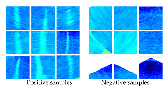
Figure 11.
Part of the positive and negative samples with different object shapes.
LBP and Haar-like descriptors are used for extracting the features of the positive and negative samples, and AdaBoost was used for getting the final detectors. Firstly, for comparison, the three detectors, which include the Haar-like detector, LBP-detector and Haar–LBP detector, were trained to detect the targets in the testing set. Then, in the case of using the same training set, testing set and bounding box generation method, the three detectors were evaluated for obtaining the optimal detector.
In Figure 12, the PRC and ROC curves of the three detectors are shown. The smooth curves show that the training model does not have the overfitting phenomenon. The closer the ROC curve is to the upper-left corner, the more targets are correctly classified; or, the closer the PR curve is to the upper-right corner, the better the model performs. It is clear that the Haar-like detector outperforms the LBP detector. Since it is difficult to compare the performance of the Haar–LBP detector and Haar-like detector from their curves directly, the AUC value of their curves can be used for comparison. As can be seen from Table 2, the AUC value of the Haar–LBP detector curve is greater than the other two, which proves that the detector proposed in this paper achieves better overall performance by combining the Haar-like and LBP features.
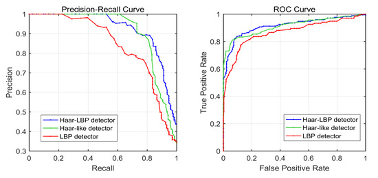
Figure 12.
ROC curves and PR curves for the Haar–LBP detector (blue), Haar-like detector (green), and LBP detector (red) applied to the testing set. In the two graphs, the curve trends of the three detectors are similar.

Table 2.
AUC value of the three detector curves.
To illustrate the effectiveness of our method, our method is compared with the state-of-the-art algorithms described in [23] and other common feature-based machine learning algorithms, including the histogram of oriented gradients (HOG) algorithm [40] and grey-level co-occurrence matrix (GLCM) [41]. In Table 3, the comparison in precision, recall and accuracy by these detectors is given. Our proposed algorithm achieves a better overall performance on these three performance indicators, which is attributed to combination of both Haar-like and LBP features.

Table 3.
Comparison result of the same testing set in precision, recall and accuracy.
- 2.
- Target Localization
By calculating the grey histogram similarity of the target boxes, the exact target-box locations can be found. In the experiment, Ping 121 is taken as an example to analyze the grey histogram distribution characteristics of the targets, as shown in Figure 13.
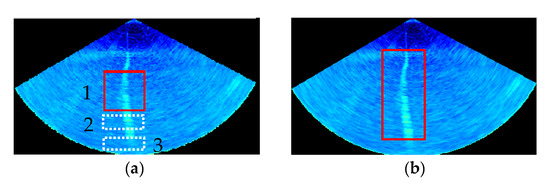
Figure 13.
(a) The MWC image with initial target detection box. In (a), 1 denotes the detected region in the target box, 2 denotes the region with the target and 3 denotes the region without gas plumes. (b) The exact target region within the target box.
In Figure 14, (a), (b) and (c) represent the grey histogram of region 1, 2 and 3, respectively, while (d), (e) and (f) represent the grey histogram of region 1, 2 and 3 in grey levels between 144 and 256. As shown in Figure 14a–c, the three grey histograms are approximately similar. By the calculation depicted in Equation. (17), the cosine similarity between (a) and (b) is 0.77, while that between (a) and (c) is 0.85. This is because the grey value of the background, which accounts for the vast majority of the image, affects the comparison of the overall similarity. According to the results of 50 Ping statistics, most of the grey values of the gas plumes in the grey-scale image are between 144 and 256, so the value 144 is used as the dividing threshold. The similarity of the histogram in the 144–256 interval of grey level is calculated to distinguish the target from the background.
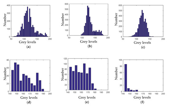
Figure 14.
The grey histogram distribution characteristics of region 1, 2 and 3 at different frequency bands. (a–c) represent the grey histogram of region 1, 2 and 3, respectively, while (d–f) represent the grey histogram of region 1, 2 and 3 in grey levels between 144 and 256.
The histogram similarity of Figure 14d,e is 0.88, while that of Figure 14d,f is 0.47. It can be seen that the grey histogram of the region with the target (Figure 14e) and that in the target box (Figure 14d) has a high similarity in the grey levels between 144 and 256. In contrast, the region without targets has few pixels in this grey interval, so the exact location of the detection box can be found by using this histogram distribution characteristics of the gas plumes.
The grey histogram similarity of the regions is calculated. The regions with the cosine similarity greater than 0.7 are merged together, and the exact location of the gas plume is obtained, as shown in Figure 13b.
- 3.
- Background Differential Segmentation
Background differential segmentation is used for getting the shape of the detected gas plume. The threshold, TdB, is a key parameter to diagnose the echoes at the same position of the neighbor MWC images to be background noise or not. To get an appropriate TdB, 20-group MWC images are obtained by randomly choosing two neighbor odd/even MWC images without gas plumes as one group. The same sectors of the 20 odd/even pings are extracted. Taking the middle sector images of these odd pings as an example, the intensity difference distribution of these chosen sector images relative to their mean sector image is shown in Figure 15a. It can be found that over 95% intensity differences vary within −2σ~2σ (σ is the standard deviation of intensity differences of the chosen sectors) and follow a Gauss distribution. Therefore, TdB is determined as 2σ or 6.6 dB in the middle sector of the odd ping. Similarly, TdB of the outside sectors of odd pings is considered as 8.9 dB. For these even pings, TdB of the middle and outside sectors are determined as 6.8 dB and 9.1 dB, respectively. By TdB, the segmentations are carried out according to Section 2.3.

Figure 15.
Determination of TdB in odd-ping middle sectors. (a) Probability density distribution of middle-sector backscatter intensity differences in the chosen 20 odd pings. (b) Curve of the standard deviations; the σs of the middle-sector backscatter intensity differences in the 20 odd pings.
After the segmentation processing, some small speckles, non-gas plumes may still remain in the MWC images. In order to make the images clearer, the morphological constraint algorithm is adopted to wipe out those speckles. According to the minimum detection resolution, the morphological parameters of gas plumes, such as area, width and height are set as 1.8 m2, 1.2 m and 1.5 m by experiments for removing these residual noises. Based on the connected component analysis, these targets more than these parameters are kept in the image, otherwise are removed. After removing these speckles, the anticipated gas plumes are remained and displayed clearly in the final MWC images.
The detected and localized gas plume (Figure 13b, Figure 16 IB) is segmented by the proposed background differential segmentation algorithm. Figure 16 depicts the background differential segmentation among three successive odd ping MWC images. In the process, the background noise image is firstly obtained by the image intersection operation depicted in Equation (18), and then is weakened by the image subtraction operation depicted in Equation (19) from the MWC images. Finally, the morphological constraint algorithm is adopted to make the gas plumes segmented completely and clearly. It can be seen from Figure 16 that:
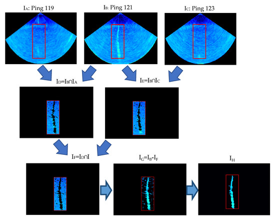
Figure 16.
A target segmented from the MWC images by the proposed background differential segmentation algorithm. Among them, the red target boxes are generated by the target localization algorithm, and then the segmentation algorithm is based on the target-box regions, which improves the efficiency of the segmentation algorithm. Ping 119, 121 and 123, named as IA, IB and IC, are three raw successive MWC images. I denote the MWC image. Symbols ∩ and – represent the image intersection operation and subtraction operation.
- The background noise is severe and always exists in the MWC images (IA, IB and IC).
- ID and IE have small differences. The public parts are found and shown in their intersection image ID and IE. The result shows that the assumption that neighbor MWC images have a similar background noise is reasonable, and the method for respectively determining the threshold TdB in different sectors of odd and even pings is correct.
- To get a common background and remain the targets in the MWC images, the intersection operation is performed again between ID and IE; and the intersection image IF, namely the background noise image, is obtained. The background noise is removed from the image IB by the subtraction operation between IB and IF. It can be seen that the segmented images IG and IF become clearer after the suppression of background noise, which shows that the proposed background differential segmentation algorithm is very efficient.
- After morphological constraint, these speckles were removed, whilst only the anticipated gas plumes remained and displayed clearly in the final image IH.
By the proposed method, the gas plumes are detected and segmented from Ping 97, 149 and 356. Figure 17 depicts the process.
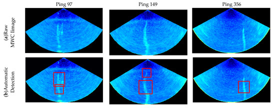

Figure 17.
Gas plumes detected and segmented by the proposed method. (a) Raw MWC images with Ping No. 97, 149 and 356; (b) gas plumes detected by the proposed Haar–LBP detector; (c) the target-box localization by the proposed target localization algorithm; (d) gas plumes segmented by the proposed differential segmentation algorithm and morphological constraint algorithm.
3.2. Detections and Segmentations of Gas Plumes in Deep Water
A deepwater MBES measurement was performed in 2018 in the water area with about a 1300 m water depth and sparse gas plumes in the South China Sea to further verify the proposed method. The whole measuring system contained a Kongsberg EM302 MBES, a Trimble SPS851 GPS receiver and a Konsberg Seatex MRU 5. The performance parameters of the Kongsberg EM302 system were as follows: depth range, 10–7000 m; beam angle, 1 × 1; maximum ping rate, 10 Hz; operating frequency, 30 kHz; swath width, 5.5 times water depth; range sampling rate, 3.25 kHz (23 cm); and effective pulse length, 0.4 ms CW to 200 ms FM. The dual-swath mode was adopted in EM710 MWC data acquisition. A 4370 km-length surveying line with roughly 7200 m swath width was carried out and 9490 pings of MWC images were recorded by SIS software. The self-developed software was utilized to process and visualize the raw MWC data for further analysis. By the proposed method, the gas plumes were quickly detected, localized and segmented from a large amount of MWC images.
Among these MWC images, due to the inhomogeneous sea structure [42], the noise distributes horizontally in different depths and exhibits a strong backscatter intensity in the deep scatter layer [10], making it difficult to distinguish the targets from the background. Moreover, the gas plumes exist in a large range and appear in dozens of consecutive MWC images. In the proposed segmentation method, the background noise cannot be obtained by the image intersection operation among the three neighboring MWC images. Under the circumstances, the proposed detection algorithm is used to detect the gas plume and find the two nearest MWC images without a gas plume. Then, the common background is acquired by their intersection operation, and the target is segmented from the background.
The three gas plumes are detected and segmented from Ping 143, 25 and 531, as shown in Figure 18. It can be seen from Figure 18a that the shape of the gas plumes in deep water is different from that in shallow water, because of currents in various directions in deep water. Meanwhile, the intensities of noise are higher than those in shallow-water images. In Figure 18b, the detection algorithm can accurately detect the target from the sea water. The target localization algorithm can adjust the position of the original detection box to locate the target exactly, as shown in Figure 18c. In Figure 18d, it can be found that even though the deep-water MWC images are seriously polluted by noise, the background differential segmentation algorithm can achieve good segmentation results.
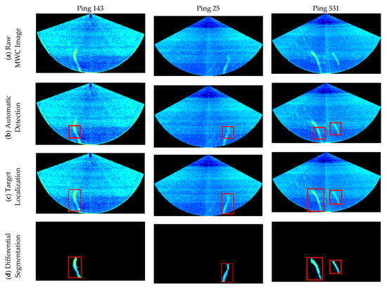
Figure 18.
Three gas plumes detected, localized and segmented from these deep-water MWC images by the proposed method. (a) Raw MWC images; (b) gas plumes detected by the proposed automatic detection algorithm; (c) the exact target-box locations obtained by the target localization algorithm; (d) gas plumes segmented by the differential segmentation algorithm and morphological constraint algorithm.
Another deep-water MBES measurement was performed in April 2014 in a water area with about a 1300 m water depth and sparse gas plumes in the Gulf of Mexico. Investigation was done using a Kongsberg EM302 MBES mounted on a pole at the bow of the ship. The EM 302 MBES allowed the acquisition of data for an operating frequency 30 kHz. Beam widths had dimensions of 1 × 1. In dual swath mode, two swaths are generated per ping cycle, with up to 864 soundings. A 3 km-long surveying line with a roughly 8000 m swath width was carried out and 976 pings of MWC images were recorded by SIS software. Self-developed software was utilized to process and visualize raw MWC data for further analysis. The gas plumes were detected, localized and segmented from Ping 40 and 249 (Figure 19).
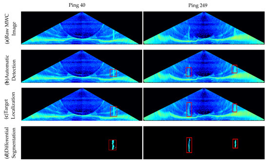
Figure 19.
Experimental results of two representative deep-water MWC images by the proposed method. (a) Raw MWC images; (b) gas plumes detected by the given automatic detection algorithm; (c) the exact target-box locations obtained by the target localization algorithm; (d) gas plumes segmented by the differential segmentation algorithm and morphological constraint algorithm.
Generally, only the MWC data inside the MSR are taken into account in MWC applications, because the seabed echoes significantly contaminate the MWC data at any slant range outside the MSR [8,10,22]. New generation deep-water MBES, such as EM 302 and 710, can decrease the interference from the seabed echoes by multi-sectors mode. According to the topography and bottom echo intensity data, it is found that the seabed of this area is relatively flat, so the seabed can be considered to be approximately homogeneous in a local area. The concept of background noise depicted in Section 2.1.3 can be extended to outside the MSR, and thus the proposed method to segment targets from the entire MWC images can be applied.
For the two deep-water MWC images (Figure 19), Ping 40 contains a short gas plume outside the MSR, where a strong side-lobe effect contaminates the MWC image; Ping 249 includes two ones outside the MSR. It can be seen that the proposed method can avoid the interference of a side-lobe effect and exactly detect the gas plumes, even those outside of MSR, which shows that the automatic detection algorithm in this paper can distinguish the noise from the target well. Then the exact target-box locations are found by the target localization algorithm. The image intersection operation obtains different or various background images (noises) from the target box. After the subtraction operation, the gas plumes remain completely and the background noises are weakened to a great extent. The results show the proposed method is effective to detect and segment gas plumes not only in the MSR but also outside the MSR.
4. Discussion
These experiments verified the correctness and effectiveness of the proposed method. By the theories and experiments, the proposed method takes the full features of the gas plume and marine environment into consideration, and has the following advantages relative to the existing methods:
- It completely realizes automatic gas plume detection in real time, and significantly improves the efficiency of the gas plume detections from MWC images, compared with existing gas plume detection methods;
- It has a high correct detection rate and strong robustness and can automatically detect gas plumes from MWC images obtained under different water depths and marine environments.
- It has complete performance and can detect the gas plume not only inside the MSR but also outside the MSR. Besides, it can achieve the detection, localization and segmentation of a gas plume, thus not only detection.
The proposed method is superior to the existing methods, but its performance may be influenced by the following factors.
4.1. Effects of the Marine Environment
Noise distributes horizontally in different depths. The physical parameters of the ocean, such as temperature, salinity, oxygen content, pressure and so on, generally present a horizontally layered structure. These characteristics of the marine environment result in the plankton generally gathering in a certain water layer and forming a strong backscatter layer with horizontal distribution in MWC images (Figure 18 and Figure 19). Two ways can remove the effect by the proposed method. Because the horizontal distribution is caused by the marine environment, it exists not only in the detected MWC image, but also in its neighboring ones, and thus the effect can be removed by the proposed background differential segmentation. Besides, the proposed morphology constraint can also be used for removing the effect due to its horizon distribution but not the vertical distribution as the detected gas plume.
Ocean currents may also affect the performance of the proposed method. Ocean currents may exist in different water layers, and lead to gas plume bending in its rising. Generally, ocean currents are small and may bring slight bending to the vertical morphology of gas plume, and it is not enough to affect the proposed method in the gas plume detection (Figure 16, Figure 17, Figure 18 and Figure 19). An extreme case may happen that the large current velocity might cause gas plume bending to the horizontal distribution. The horizontal gas plume can be detected by the proposed method, but it may be recognized as a non-interested target and may be removed in the morphology constraint. Because the horizontal gas plume has a similar BS as the vertical one, it can be remained by the characteristics of its BS.
4.2. Effect of the MBES Measuring Model and Seabed Side Lobe Effect
The MBES transducer generally transmits high-frequency pulses in interior sectors and low-frequency pulses in outside sectors in a ping measurement. The measuring model produces a higher noise in the two sides of the MWC image than in the interior of the MWC image (Figure 16, Figure 17, Figure 18 and Figure 19). Moreover, the MWC data outside of the MSR is often removed because of the serious seafloor side lobes effect, and only the MWC data in the MSR can be used for the detection (Figure 16, Figure 17 and Figure 18). The MWC data in the MSR are only adopted in the studies depicted in the literature [1,42,43]. To detect gas plumes in whole MWC images, the two sides of the MWC image and the outside of the MSR were chosen as the negative samples, depicted in Section 2.1.3, to overcome the effect on the correct detection rate of the proposed method. For the new generation MBES, such as EM 302 and 710, these can decrease the interference from the seabed echoes by multi-sectors measuring mode and improve the MWC image outsides of the MSR. The impossibility in existing gas plume detection becomes possible because of the assumption that the seabed is approximately homogeneous in a local area and the differential elimination of background noise, as depicted in Section 2.1.3. However, the examples presented in Figure 19 contain relatively little background interference. Because of the lack of data, it is hard to assess the effectiveness of the algorithm at reducing sidelobe interference. Undeniably, the proposed method may become inefficient when the image of the gas plume is almost completely merged into the high-noise image, such as that in the two sides of the MWC image or outside MSR.
4.3. Effect of Targets with a Strong Backscatter Strength
Fish schools and aquatic plants have strong BSs and a similar texture and shape features as gas plumes and may have an effect on the correct detection rate of the proposed method. The literature [44,45,46,47] provides fish–gas discrimination protocols, quantification of seep-related methane gas emissions, macroalgae detection using acoustic imaging and a means to quantify and assess fishes or fish schools in the presence of gas bubbles, which may be useful for discriminating gas plumes from fish schools and aquatic plants. Besides, the characteristics of the backscatter intensity differences between gas plumes and the other targets with the approximate features as gas plumes need to be deeply analyzed for further enhancing the correct detection rate and the segmentation algorithm. Moreover, most of the gas plumes are perpendicular to the seabed while other targets are not, so this characteristic can be used to distinguish them.
4.4. Effects of Large Gas Plume and Complicated Water Environment
In the proposed method, the differential segmentation method is based on the assumption that the background noise is approximately the same in a local water area. Two neighboring non-target MWC images are used for getting the background noise. If the water environment is complicated and the detected gas plume is large and appears in the three neighboring MWC images [22,42,43], the three neighboring MWC images are not enough to pick out the actual background noise. Under the situation, it is recommended to use more near non-target MWC images, such as 7 or 9 MWC images, to estimate the background noise and then remove it by the differential segmentation algorithm.
5. Conclusions
This paper proposes a gas plume detection and segmentation method, which can achieve the detection, localization and segmentation of gas plumes from a whole MWC image. Due to taking the feature differences between the gas plumes and non-gas plumes into account, the proposed gas plume automatic detection algorithm based on the AdaBoost cascade classifier, combining the Haar-like and LBP features, automatically realizes the detection of the gas plume under different water depths and marine environments, and achieves a detection accuracy of 95.8%, precision of 99.35% and recall of 82.7%, which is better than the other classic detection methods. Considering the differences in gas plumes and background noise in BSs, the proposed target localization algorithm based on histogram similarity calculation accurately localizes the detected gas plume boxes and obtains complete gas plume images. On account of the local invariance of the marine environment and the features of the gas plumes, the proposed background differential segmentation method based on image intersection and subtraction operation accurately segments the outline and shape of the detected gas plume.
The proposed method significantly improves the efficiency and accuracy relative to the existing detections, as well as the reliability and efficiency relative to the current semi-automatic threshold segmentation method. It provides a fully automatic and exact approach for gas plume detection and segmentation from MWC data.
Author Contributions
Conceptualization, D.M., J.Z. and H.Z.; funding acquisition, J.Z.; investigation, D.M. and J.Z.; methodology, D.M. and J.Z.; software, D.M. and S.W.; supervision, J.Z. and H.Z.; visualization, D.M.; writing—original draft, D.M.; writing—review and editing, J.Z. and H.Z. All authors have read and agreed to the published version of the manuscript.
Funding
This research was funded by the National Key R&D Program of China, grant number 2016YFB0501703, Scientific Research Project of Shanghai Municipal Oceanic Bureau, grant number huhaike2020-01 and huhaike2020-07, and Key Technology for Detection and Monitoring of Channel Regulating Structures in Yangtze River.
Acknowledgments
The authors would like to thank the editors and anonymous reviewers for their comments and suggestions. The data in this paper is provided by Guangzhou Marine Geological Survey Bureau. We greatly appreciate their support.
Conflicts of Interest
The authors declare no conflict of interest. The founding sponsors had no role in the design of the study; in the collection, analyses, or interpretation of data; in writing the manuscript; and in the decision to publish the results.
References
- Gee, L.; Doucet, M.; Parker, D.; Weber, T.; Beaudoin, J. Is Multibeam Water Column Data Really Worth the Disk Space? In Proceedings of the Hydro12-Taking Care of the Sea, Rotterdam, The Netherlands, 13–15 November 2012. [Google Scholar]
- Yang, F.L.; Han, L.T.; Wang, R.F.; Shi, B. Progress in object detection in middle and bottom-water based on multibeam water column image. J. Shandong Univ. Sci. Technol. Nat. Sci. 2013, 32, 75–83. [Google Scholar]
- Idczak, J.; Brodecka-Goluch, A.; Łukawska-Matuszewska, K.; Graca, B.; Gorska, N.; Klusek, Z.; Pezacki, P.D.; Bolałek, J. A geophysical, geochemical and microbiological study of a newly discovered pockmark with active gas seepage and submarine groundwater discharge (MET1-BH, central Gulf of Gdańsk, southern Baltic Sea). Sci. Total Environment. 2020, 742. [Google Scholar] [CrossRef]
- Medialdea, T.; Somoza, L.; León, R.; Farran, M.; Ercilla, G.; Maestro, A.; Casas, D.; Llave, E.; Hernández-Molina, F.; Fernández-Puga, M.C.; et al. Multibeam backscatter as a tool for sea-floor characterization and identification of oil spills in the Galicia Bank. Mar. Geol. 2008, 249, 93–107. [Google Scholar] [CrossRef][Green Version]
- Sacchetti, F.; Benetti, S.; Georgiopoulou, A.; Dunlop, P.; Quinn, R. Geomorphology of the Irish Rockall Trough, North Atlantic Ocean, mapped from multibeam bathymetric and backscatter Data. J. Maps. 2011, 7, 60–81. [Google Scholar] [CrossRef]
- Janowski, L.; Madricardo, F.; Fogarin, S.; Kruss, A.; Molinaroli, E.; Kubowicz-Grajewska, A.; Tegowski, J. Spatial and Temporal Changes of Tidal Inlet Using Object-Based Image Analysis of Multibeam Echosounder Measurements: A Case from the Lagoon of Venice, Italy. Remote Sens. 2020, 12, 2117. [Google Scholar] [CrossRef]
- Gaida, T.C.; Van Dijk, T.A.; Snellen, M.; Vermaas, T.; Mesdag, C.; Simons, D.G. Monitoring underwater nourishments using multibeam bathymetric and backscatter time series. Coast. Eng. 2020, 158. [Google Scholar] [CrossRef]
- Hughes Clarke, J.E. Applications of multibeam water column imaging for hydrographic survey. Hydrogr. J. 2006, 120, 3–14. [Google Scholar] [CrossRef]
- Clarke, J.H.; Lamplugh, M.; Czotter, K. Multibeam water column imaging: Improved wreck least-depth determination. In Proceedings of the Canadian Hydrographic Conference, Halifax, NS, Canada, 5–9 June 2006. [Google Scholar]
- Marques, C.R.; Hughes Clarke, J.E. Automatic mid-water target tracking using multibeam water column. In Proceedings of the CHC 2012 The Arctic, Old Challenges New, Niagara Falls, ON, Canada, 15–17 May 2012. [Google Scholar]
- Innangi, S.; Bonanno, A.; Tonielli, R.; Gerlotto, F.; Innangi, M.; Mazzola, S. High resolution 3-D shapes of fish schools: A new method to use the water column backscatter from hydrographic MultiBeam Echo Sounders. Appl. Acoust. 2016, 111, 148–160. [Google Scholar] [CrossRef]
- Hoffmann, J.J.L.; Schneider von Deimling, J.; Schröder, J.F.; Schmidt, M.; Held, P.; Crutchley, G.J.; Scholten, J.; Gorman, A.R. Complex Eyed Pockmarks and Submarine Groundwater Discharge Revealed by Acoustic Data and Sediment Cores in Eckernförde Bay, SW Baltic Sea. Geochem. Geophys. Geosyst. 2020, 21. [Google Scholar] [CrossRef]
- Lohrberg, A.; Schmale, O.; Ostrovsky, I.; Niemann, H.; Held, P.; Schneider von Deimling, J. Discovery and quantification of a widespread methane ebullition event in a coastal inlet (Baltic Sea) using a novel sonar strategy. Sci. Rep. 2020, 10, 4393. [Google Scholar] [CrossRef]
- Nikolovska, A.; Sahling, H.; Bohrmann, G. Hydroacoustic methodology for detection, localization, and quantification of gas bubbles rising from the seafloor at gas seeps from the eastern Black Sea. Geochem. Geophys. Geosyst. 2008, 9. [Google Scholar] [CrossRef]
- Gardner, J.V.; Malik, M.; Walker, S. Plume 1400 meters high discovered at the seafloor off the northern California margin. Eos Trans. Am. Geophys. Union 2009, 90, 275. [Google Scholar] [CrossRef]
- Weber, T.; Jerram, K.; Mayer, L. Acoustic sensing of gas seeps in the deep ocean with split-beam echosounders. Proc. Meet. Acoust. 2012, 17, 070057. [Google Scholar] [CrossRef]
- Philip, B.T.; Denny, A.R.; Solomon, E.A.; Kelley, D.S. Time series measurements of bubble plume variability and water column methane distribution above southern hydrate ridge, Oregon. Geochem. Geophys. Geosyst. 2016, 17, 1182–1196. [Google Scholar] [CrossRef]
- Colbo, K.; Ross, T.; Brown, C.; Weber, T. A review of oceanographic applications of water column data from multibeam echosounders. Estuar. Coast. Shelf Sci. 2014, 145, 41–56. [Google Scholar] [CrossRef]
- QPS. Fledermaus; v7.5.2 Manual; QPS: Zeist, The Netherlands, 24 February 2016. [Google Scholar]
- Collins, C.M. The Progression of Multi-Dimensional Water Column Analysis. In Proceedings of the Hydro12-taking Care of the Sea, Rotterdam, The Netherlands, 13–15 November 2012. [Google Scholar]
- Veloso, M.; Greinert, J.; Mienert, J.; De Batist, M. A new methodology for quantifying bubble flow rates in deep water using splitbeam echosounders: Examples from the arctic offshore nw-svalbard. Limnol. Oceanogr. Methods 2015, 13, 267–287. [Google Scholar] [CrossRef]
- Urban, P.; Köser, K.; Greinert, J. Processing of multibeam water column image data for automated bubble/seep detection and repeated mapping. Limnol. Oceanogr. Methods 2017, 15, 1–21. [Google Scholar] [CrossRef]
- Zhao, J.; Meng, J.; Zhang, H.; Wang, S. Comprehensive Detection of Gas Plumes from Multibeam Water Column Images with Minimisation of Noise Interferences. Sensors 2017, 17, 2755. [Google Scholar] [CrossRef]
- Rhinelander, J. Feature extraction and target classification of side-scan sonar images. In Proceedings of the 2016 IEEE Symposium Series on Computational Intelligence (SSCI), Athens, Greece, 6–9 December 2016; pp. 1–6. [Google Scholar]
- Yang, F.; Du, Z.; Wu, Z. Object Recognizing on Sonar Image Based on Histogram and Geometric Feature. Mar. Sci. Bull. 2006, 25, 64–69. [Google Scholar] [CrossRef]
- Isaacs, J.C. Sonar automatic target recognition for underwater UXO remediation. In Proceedings of the 2015 IEEE Conference on Computer Vision and Pattern Recognition Workshops (CVPRW), Boston, MA, USA, 7–12 June 2015; pp. 134–140. [Google Scholar]
- Lienhart, R.; Maydt, J. An extended set of Haar-like features for rapid object detection. In Proceedings of the International Conference on Image Processing, Rochester, NY, USA, 22–25 September 2002. [Google Scholar]
- Huang, C.C.; Tsai, C.Y.; Yang, H.C. An Extended Set of Haar-like Features for Bird Detection Based on AdaBoost. In Proceedings of the International Conference on Signal Processing, Image Processing, and Pattern Recognition, Jeju Island, Korea, 8–10 December 2011. [Google Scholar]
- Park, K.Y.; Hwang, S.Y. An improved Haar-like feature for efficient object detection. Pattern Recognit. Lett. 2014, 42, 148–153. [Google Scholar] [CrossRef]
- Zhang, S.; Bauckhage, C.; Cremers, A.B. Informed Haar-Like Features Improve Pedestrian Detection. In Proceedings of the Computer Vision & Pattern Recognition, Columbus, OH, USA, 23–28 June 2014. [Google Scholar]
- Nie, T.; Han, X.; He, B.; Li, X.; Liu, H.; Bi, G. Ship Detection in Panchromatic Optical Remote Sensing Images Based on Visual Saliency and Multi-Dimensional Feature Description. Remote Sens. 2020, 12, 152. [Google Scholar] [CrossRef]
- Kongsberg. Kongsberg em Series multibEam Echo Sounder em Datagram Formats. Available online: https://www.km.kongsberg.com/ks/web/nokbg0397.nsf/AllWeb/253E4C58DB98DDA4C1256D790048373B/$file/160692_em_datagram_formats.pdf (accessed on 18 July 2016).
- Papageorgiou, C.P.; Oren, M.; Poggio, T. A general framework for object detection. In Proceedings of the Sixth International Conference on Computer Vision (ICCV1998), Bombay, India, 4–7 January 1998; pp. 555–562. [Google Scholar]
- Viola, P.A.; Jones, M.J. Rapid object detection using a boosted cascade of simple features. In Proceedings of the 2001 IEEE Computer Society Conference on Computer Vision and Pattern Recognition (CVPR 2001), Kauai, HI, USA, 8–14 December 2001; pp. 511–518. [Google Scholar]
- Viola, P.; Jones, M.J. Robust real-time face detection. Int. J. Comput. Vis. 2004, 57, 137–154. [Google Scholar] [CrossRef]
- Ojala, T.; Pietikainen, M.; Maenpaa, T. Multiresolution gray-scale and rotation invariant texture classification with local binary patterns. IEEE Trans. Pattern. Anal. Mach. Intell. 2002, 24, 971–987. [Google Scholar] [CrossRef]
- Zhuang, X.; Kang, W.; Wu, Q. Real-time vehicle detection with foreground-based cascade classifier. IET Image Process. 2016, 10, 289–296. [Google Scholar] [CrossRef]
- Davis, J.; Goadrich, M. The relationship between Precision-Recall and ROC curves. In Proceedings of the 23rd International Conference on Machine Learning, New York, NY, USA, 25–29 June 2006; pp. 233–240. [Google Scholar]
- Solomon, C.; Breckon, T. Fundamentals of Digital Image Processing; John Wiley & Sons, Ltd.: Chichester, UK, 2011; p. 197. [Google Scholar]
- Dalal, N.; Triggs, B. Histograms of Oriented Gradients for Human Detection. In Proceedings of the 2005 IEEE Computer Society Conference on Computer Vision and Pattern Recognition (CVPR’05), San Diego, CA, USA, 20–25 June 2005; Volume 1, pp. 886–893. [Google Scholar]
- Ohanian, P.P.; Dubes, R.C. Performance evaluation for four classes of textural features. Pattern Recognit. 1992, 25, 819–833. [Google Scholar] [CrossRef]
- Waite, A. Sonar for Practising Engineers; John Wiley & Sons Ltd.: Chichester, UK, 2002; p. 103. [Google Scholar]
- Weber, T.; Peña, H.; Jech, J.M. Consecutive acoustic observations of an atlantic herring school in the northwest atlantic. ICES J. Mar. Sci. 2009, 66, 1270–1277. [Google Scholar] [CrossRef]
- Judd, A.; Davies, G.; Wilson, J.; Holmes, R.; Baron, G.; Bryden, I. Contributions to atmospheric methane by natural seepages on the u.K. Continental shelf. Mar. Geol. 1997, 140, 427–455. [Google Scholar] [CrossRef]
- Ostrovsky, I. Hydroacoustic assessment of fish abundance in the presence of gas bubbles. Limnol. Oceanogr. Methods 2009, 7, 309–318. [Google Scholar] [CrossRef]
- Kruss, A.; Tęgowski, J.; Tatarek, A.; Wiktor, J.; Blondel, P. Spatial distribution of macroalgae along the shores of Kongsfjorden (West Spitsbergen) using acoustic imaging. Pol. Polar Res. 2017, 38, 205–229. [Google Scholar] [CrossRef][Green Version]
- Von Deimling, J.S.; Rehder, G.; Greinert, J.; McGinnnis, D.; Boetius, A.; Linke, P. Quantification of seep-related methane gas emissions at tommeliten, north sea. Cont. Shelf Res. 2011, 31, 867–878. [Google Scholar] [CrossRef]
© 2020 by the authors. Licensee MDPI, Basel, Switzerland. This article is an open access article distributed under the terms and conditions of the Creative Commons Attribution (CC BY) license (http://creativecommons.org/licenses/by/4.0/).