Article

Evaluation of Nearshore and Offshore Water Quality Assessment Using UAV Multispectral Imagery

1
Gravity Marine, 32617 SE 44th St., Fall City, WA 98024, USA
2
The Entangled Bank Laboratory, 11 Rue Anatole France, 66650 Banyuls sur Mer, France
*
Author to whom correspondence should be addressed.
Remote Sens. 2020, 12(14), 2258; https://doi.org/10.3390/rs12142258
Submission received: 14 June 2020 / Revised: 3 July 2020 / Accepted: 11 July 2020 / Published: 14 July 2020
(This article belongs to the Section Ocean Remote Sensing)

Abstract

:
A cost-effective technology has emerged which combines multispectral sensors mounted on Unmanned Aerial Vehicles (UAVs). This technology has a promising potential for monitoring water quality in coastal environments. Our study aimed at evaluating this technology to infer the spatial distribution of chlorophyll a concentration [Chl-a] (in µg·L−1) and turbidity (FNU) in surface waters. The multispectral sensor measured reflectance at 4 distinct wavelength bands centered on 448 nm, 494 nm, 550 nm and 675 nm, hence providing 4 datasets {R(448), R(494), R(550), R(675)}. We investigated the potential of estimating [Chl-a] and turbidity based on reflectance ratios and indexes calculated from two different wavelength bands. The calibration functions were formulated based on the property that any of the reflectance measurements was linearly correlated to any other one. The calibration was performed from 35 measurements of reflectance, [Chl-a] and turbidity collected in seven sites in the U.K. between May and August 2017. Two calibration functions derived from the index δ=(R(550) − R(448))/(R(550) + R(448)) presented the best fit and explained 78% of the total variance for [Chl-a] and 74% for turbidity measurements, respectively. Calibration functions were then inversed to estimate [Chl-a] and turbidity from reflectance measurements. Finally, we performed a validation test using independent measurements from three sites in France, in July 2017. The resulting maps show a pattern with higher [Chl-a] in lower turbidity areas. However, discrepancies between the observed and re-calculated values and difficulties in validating low turbidity values suggest that site-specific calibrations should be performed at each investigated location.

Graphical Abstract

1. Introduction

The need to monitor water quality in coastal regions is becoming increasingly important as populations and associated development continue to increase. The increasing demands on land use including the proliferation of housing developments, increased agricultural production, and changes in forestry management practices, impact nearby aquatic ecosystems. The increased productivity of pelagic primary producers and decreased water column transparency are known to be the first consequences of eutrophication in both freshwater and coastal ecosystems [1]. The increase of overland flow due to impervious surfaces increases nutrient and sediment loads in receiving coastal watersheds [2,3]. In an effort to promote sustainable use of the seas and the conservation of marine ecosystems the European Union has outlined a framework directive for its members, which requires them to monitor the health of marine ecosystems, including specifically, turbidity and phytoplankton [4]. Developing cost effective methods and tools to monitor water quality is essential to control ecosystem health on a long-term time scale and is crucial to implement sustainable management practices for coastal aquatic ecosystems. The use of unmanned aerial vehicles mounted with multispectral sensors for water quality monitoring offers a possible economical solution for monitoring water quality in coastal areas.
Remote sensing of the earth’s surface by satellites has provided a way to quantify changes in the ocean in recent decades. These multi-decade satellite records have also opened-up opportunities to improve upon and find new ways of measuring water quality parameters throughout the world’s oceans. Most remote sensing methods use optical properties of water to assess water quality, mainly by two variables, turbidity which generally refers to a measure of reduced water clarity and chlorophyll a concentration [Chl-a] which is used as a proxy to estimate phytoplankton biomass. The methods to measure ocean water quality parameters using satellite-based remote sensing technology has been studied for many decades. Obtaining water quality estimates through remote sensing is typically accomplished using empirical formulas based on statistical regression analysis of reflectance values at the location of in-situ measurements [5,6,7,8]. The evolution of NASA’s Ocean Color algorithms are a great example of the achievements made in satellite-based remote sensing capabilities over the years. O’Reilly et al. [9] in 1998 used in-situ measurements from 919 stations to analyze 17 different algorithms using reflectance values derived from SeaWiFS wavebands. Of these, the best performing algorithms became known as the Ocean Color (OC) algorithms, often referred to as OCx (x being an index indicating the sensor, algorithm and wavelengths used to fit polynomial functions). The basis of these algorithms is the logarithm of the ratio of 2 different bands. Retrieval algorithms for both turbidity and [Chl-a] are readily available. Scientists continue to bring in new data, environmental factors and technology to modify the existing algorithms and develop new models.
The use of satellite imagery, however, is limited by its lack of an adequate spatial resolution in-land and coastal features [10,11,12]. Unmanned Aerial Vehicles (UAVs), have become a cost-effective tool for the collection of high-resolution aerial imagery [13,14,15], which includes possible applications, for monitoring water quality [16,17,18,19] and sea-ice [20]. Current advances in digital camera technology have allowed for the development of small, lightweight and affordable multispectral cameras that can be mounted on UAVs. In contrast to the multiple narrow wavebands of hyperspectral technology, multispectral sensors use broader wavebands to collect imagery from multiple wavebands in the visible and near-infrared spectrums. These sensors deployed in lower altitude exhibit higher resolutions than satellite multi-spectral cameras [21]. Primarily they have been used by farmers to monitor crop production and plant health [22]. Their applications in the marine environment, however, are minimally documented.
The objective of our study is to provide an initial assessment of the use of this new technology to investigate water quality of coastal ecosystem. We proposed to evaluate the use of a multispectral sensor mounted on a small UAV for estimating the spatial distribution of both turbidity and chlorophyll a concentration [Chl-a] as proxies of water quality. For this, a series of surveys were first performed in nearshore and offshore marine environments on the south coast of England; they were used to test the methodology and to develop a calibration algorithm to calculate estimators. Algorithms were constructed mathematically by examining how reflectance measurements varied relative to each other. Calibration functions were formulated, and the variability of parameter estimates were quantified as a mean to evaluate the methodology (i.e., how dispersion influences the precision of the estimators). In a second step, this methodology was implemented on independent sets of data collected along the coast of Western Brittany, France. These reflectance datasets were used to reconstruct the spatial distribution of the resulting [Chl-a] and turbidity estimates.

2. Materials and Methods

2.1. Study Area

This study collected both in-situ and multispectral imagery data from three main regions (Figure 1): two regions are located in Southern England, U.K. encompassing three nearshore sites near Southampton, and four offshore sites off the coast of Plymouth. The second region is located in Western Brittany, France, and encompasses three nearshore sites around Brest. The U.K. sites were sampled between the 9th of May and the 6th of August 2017. The three nearshore sites in France were each surveyed one time from the 12th to the 16th of June 2017.

2.2. Sampling Strategy

In-situ measurements were collected using two different methods based on location: (1) At the U.K. sites, samples were collected at three to six- discrete locations, which were surveyed a total of 11 times over the course of the study. The four offshore sites in the U.K. were surveyed once during a water quality research cruise on June 19th–21st, 2017, with the University of Southampton onboard R/V Callista; (2) The in-situ measurements collected in France utilized a boat to tow the water quality probe and measure continuous water quality and GPS measurements along transects, instead of a single, discrete point location. The data collected in France was used to validate the models developed from data collected at the U.K. sites.

2.3. Methods

2.3.1. In-Situ Measurements

A YSI (Yellow Springs Instruments) EXO1 water quality probe was used to measure in-situ data for [Chl-a] and turbidity. Turbidity was measured in Formazin Nephelemotric Units (FNU) by an optical sensor installed on the probe which emits light at 860 nm (±15 nm) and detects 90° scatter. [Chl-a] was measured by an optical sensor that excites chlorophyll a with light emitted at 470 nm (±15 nm) and measures fluorescence at 685 nm (±20 nm). [Chl-a] was expressed in micrograms per liter (µg·L−1) after calibration in the laboratory. Both fluorescence and turbidity sensors were factory calibrated before the project. A handheld display unit with an internal GPS (±2.5 m accuracy) was connected to the EXO1 probe for real-time readings of water quality parameters (Figure 2b). In-situ measurements at the nearshore sites in the U.K. were sampled by wading out into the water to a depth of approximately 1 m and filling a 5-gallon sample bucket of undisturbed water, then marking a location with the handheld GPS device. Once back as shore, the EXO1 was placed into the sample bucket to collect the measurements. For offshore sites, in-situ measurements were collected from an approximate depth of 3 m with Niskin bottles mounted on a CTD rosette. Additionally, water samples were collected at all U.K. sites to analyze [Chl-a] by fluorometry in the laboratory, in order to calibrate the YSI EXO1 handheld probe. A Turner Designs 10-AU Fluorometer was used to measure [Chl-a] of the water samples, according to the methods described by Welschmeyer (1994) [23].

2.3.2. UAV Multispectral Surveys

The UAV used in this study was a DJI Phantom 3 Professional. The built-in GPS was used for positioning with a horizontal accuracy range of ±1.5 m and a vertical accuracy range of ±0.5 m. The UAV was equipped with a multispectral sensor system built by Sentera in Minneapolis, Minnesota, U.S.A. The multispectral sensor consists of four different wave band sensors in the visible spectrum (Table 1). Each sensor collects 1.2-megapixel (1248 × 950) images at user defined intervals. The approximate footprint for each image at 75 m in altitude was 60 m × 45 m, hence the resolution was equal to 4.8 cm/pixel. Autonomous operation of the UAV survey was performed utilizing Sentera software application called AgVault™. All UAV surveys for this study were designed to have a minimum sidelap of 70% on all transects. The maximum flight speed was 8 ms−1. The multispectral system was configured to capture one image for each waveband every 20 m of distance flown. All UAV flights and in-situ measurements were carried out during daylight, between 12:00 and 19:30. Each survey began and ended by imaging a 20 cm × 15 cm radiometric calibration target to calibrate images to the light conditions available at the time of the flight. The global meteorological conditions varied between sunny and cloudy weather. Flights were always performed below the cloud cover. No flights were conducted in rain, wind speeds higher than 15 kts or wave heights higher than 1 m due to the risk of measuring unusable data and losing or damaging the UAV. In-situ measurements were collected within 30 min of each UAV flight.

2.4. Data Processing

2.4.1. Image Reflectance Correction

To convert the raw pixel values from each multispectral image into a quantifiable reflectance value, a reflectance correction process (Equation (1)) was developed with guidance from the sensor manufacturer and executed in a 2-step process. The first step is to calculate a constant that represents the available light conditions at the time of each survey. This process uses the images of the radiometric calibration target to calculate a reflectance constant for each waveband, k (FPA counts/µs−1). The Focal Plane Array (FPA), the array of light detectors which are located in the focal plane of the sensor, is parameterized by TE (microseconds, µs), the analog gain, GA (unitless) and the digital gain, GD (unitless). Each image has unique settings (TE,GA,GD), which are recorded in a separate log file by the sensor on every flight.
The aperture, filter width and quantum efficiency for each image are integrated into the calibration constant (k). The second step of the process uses the calculated reflectance constant (k) and converts each pixel’s digital number (ND) ranging from 0 to 255, into digital reflectance values, RD (in digital number):
R D = N D k T E     G A     G D
which is converted into relative reflectance, R (in %), by:
R = 100 R D 256

2.4.2. Image Mosaics

Multispectral images taken nearshore sites were processed to create georeferenced mosaics using the software Pix4D™. The creation of mosaics for each waveband was performed by Pix4Dmapper using image stitching techniques based on tie points identification [24] and correction of images from variations in the camera angle and distance from the ground. The algorithm is used to sequentially stitch images from an initial pair to produce a seamless orthomosaic [25].

2.4.3. Reflectance Value Extraction

A total of 35 measurements, from the U.K sites, were used for developing calibration algorithms. Data collected from in-situ samples were compared to the multispectral mosaics with a 1 × 1 m, 3 × 3 m and 5 × 5 m averaged reflectance value calculated at the same location. The applied averaging accounts for the accuracy of the GPS and the time lag between the collection of the UAV data and the in-situ measurements. In-situ sample locations were selected to keep only points with homogeneous bottom types (e.g., sandy bottom), avoiding seagrass beds or other areas with strong local variability. Regarding the offshore sites, the averaging area was performed at 25 × 25 m assuming that the field is quite homogeneous regarding the explored variable, [Chl-a] and turbidity. No mosaic was created in this case, hence a single image was used because there was no stationary objects available to guide the merging program.

3. Results

3.1. In-Situ Data Analysis

We have first investigated the relationship between each of the wavelength band reflectance measurements and environmental variables. Temperature and Salinity are variables used to characterize differences in water masses, and as they varied extensively (12 °C to 26 °C and 4 to 36 psu respectively), they may differ in optical properties. Ambient Light Energy (estimated as total incident light irradiance at the sea surface) is one factor that effects the most reflectance measurements. Even if there was a systematic calibration of the measurements using standards with known reflectance values, ambient light energy may affect reflectance measurements. Chlorophyll a concentration and turbidity are the two variables that we targeted to infer water quality. Temperature, salinity, turbidity and chlorophyll a concentration were measured, hence calibrated, by the sensor manufacturer or by us. On the contrary, the total incident light irradiance was calculated from the geographical position of the sampling stations, and the date and time of each of the sampling according to Frouin et al. 1989 [26].
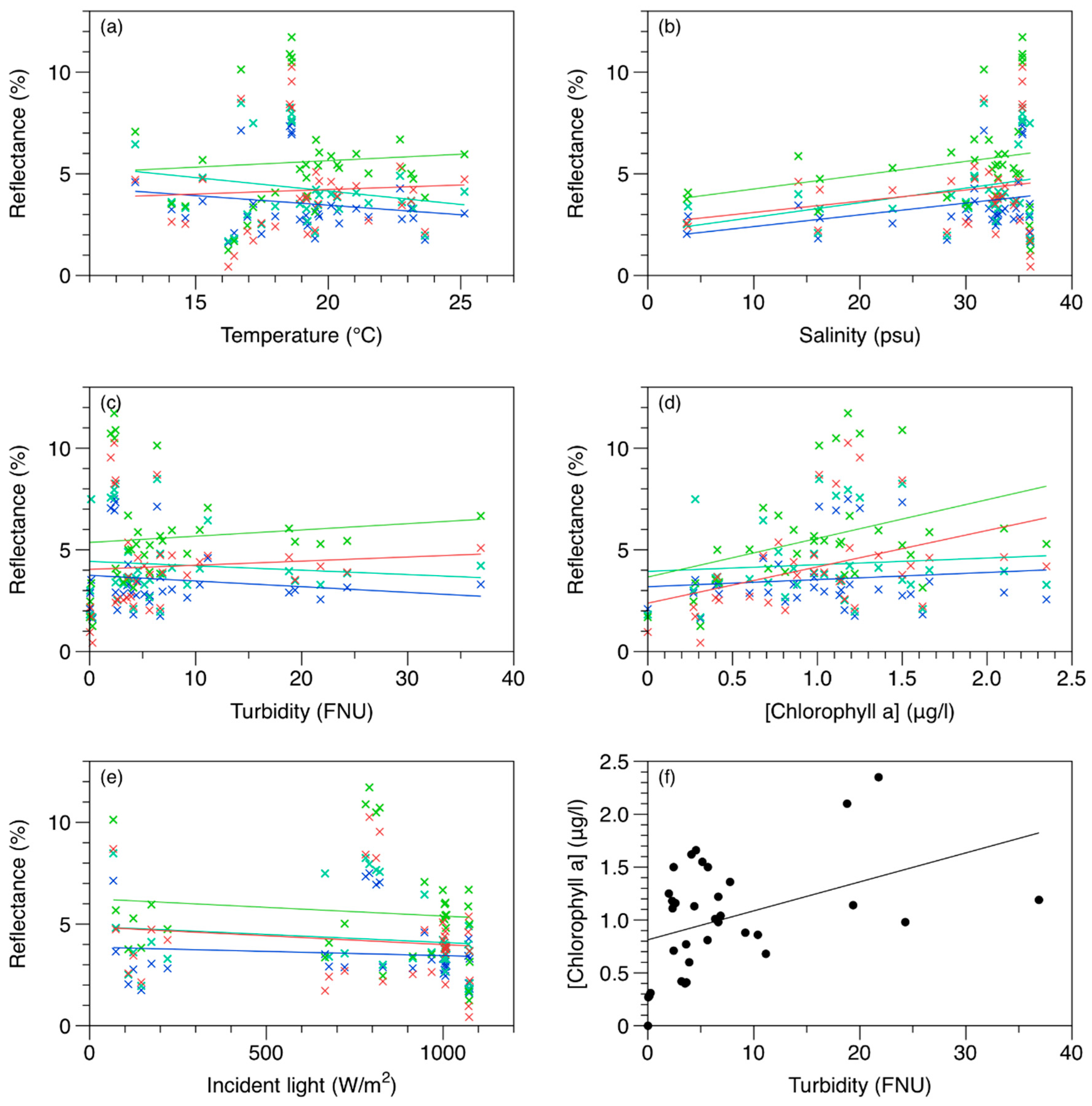
Figure 2 represents the variations of reflectance according to the environmental variables (temperature, salinity, turbidity, chlorophyll a and light energy). The slopes were different from one reflectance to another, but none of them were significantly different from zero in any of the cases (t-test performed with degrees of freedom (d.o.f), equal to 33 and a first-type error threshold fixed at 0.05). This indicates that none of the reflectance measurement was sensitive to variations of these environmental variations, i.e. their intrinsic variability (random dispersion around the mean value) is much larger than variations induced by environmental variability.
The relationship between the two environmental variables of interest (chlorophyll a concentration and turbidity) were investigated by means of orthogonal regression. [Chl-a] measurements were distributed close to the mean of 1.02 ± 0.52 SD µg·L−1. The distribution of turbidity measurements was right-skewed with a mean of 7.23 ± 7.94 FNU. The orthogonal linear regression between in-situ measurements of turbidity and [Chl-a] resulted in a positive linear relationship, but the proportion of variance explained by the linear regression is low (R² = 0.17). In addition, it did not reveal any significant correlation since the slope was not significantly different from zero, (t-tests, d.o.f. = 33, p = 0.05), because of high dispersion of the values. Therefore, they can be assumed to be independent of each other.

3.2. Multispectral Data Analysis

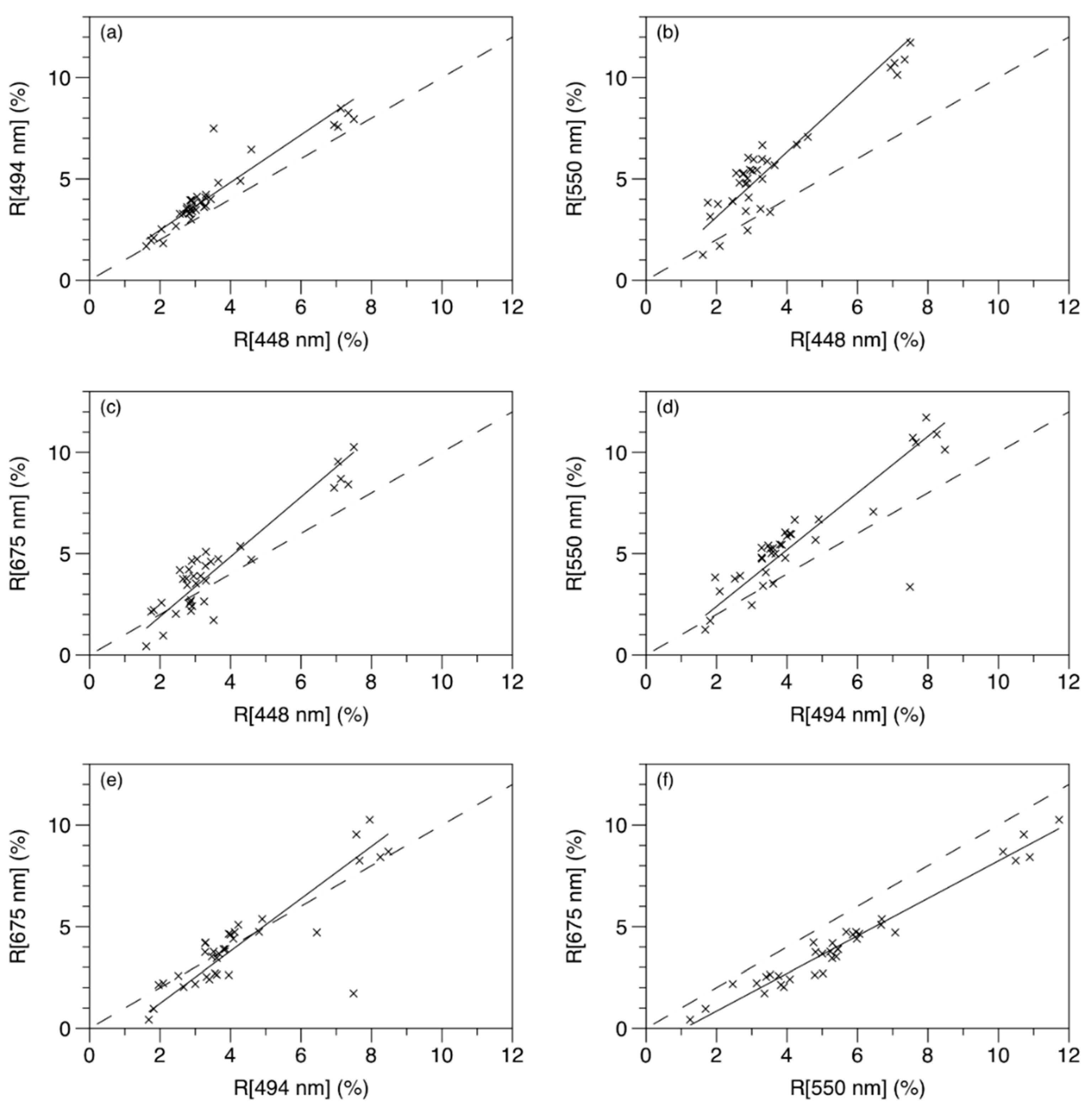
Orthogonal regressions between the reflectance data shows that each of the waveband measurements are strongly linearly correlated to any other (Figure 3, Table 2); the percentage of variance explained by the regression varied between 0.69 (reflectance measured at 494 vs. 675 nm) and 0.96 (reflectance measured at 550 vs. 675 nm). The slopes varied from 0.92 (reflectance measured at 550 vs. 675 nm) to 1.60 (reflectance measured at 448 vs. 550 nm), and corresponding intercepts varied from −1.35% (reflectance measured at 494 vs. 675 nm) to 0.13 % (reflectance measured at 448 vs. 494 nm). Correlation between reflectance from each of the single wave bands compared to the measured in-situ values for both [Chl-a] and turbidity, were not significant. However, the level of reflectance varied from one waveband to another, 7.45 ± 1.69 SD at 448 nm, 9.59 ± 3.10 SD at 494 nm, 12.02 ± 3.67 SD at 550 nm and 8.52 ± 3.22 SD at 675 nm.

3.3. Algorithm Development

The covariations between reflectance measurements performed at one wavelength, R1, and measurements performed at any other wavelength band, R2, both being interchangeable, are expressed by R1 = aR2+b, where a is the slope and b the intercept of the orthogonal regression between R1 and R2. To combine differences in the level of reflectance between two wavelength bands and the variables of interest ([Chl-a] and turbidity), we first calculated indices based on the ratios between these two wavelengths. This ratio, ρ12 (dimensionless) was developed as the following:
ρ 12 = R 1 R 2 = aR 2 + b R 2 = a + b R 2
Therefore, the ratio ρ12 has structurally the shape of a hyperbolic function. The minimum calibration function that links environmental variables, E (chlorophyll a concentration or turbidity), to the ratio ρ12 can then be expressed as:
ρ 12 = x 1 + x 2 E 1
where x1 and x2 are two parameters to estimate. The exponent of the environmental variable, E, is equal to (−1), 1 being a particular value of a parameter x3, {x3 ∈ ℝ}, hence (4) can be generalized as:
ρ 12 = x 1 + x 2 E x 3
with the constraint that x2 is negative and represents the relative asymmetry between the distributions of the reflectance ratio, ρ12 and the environmental variable, E ([Chl-a] or turbidity).
The reciprocal function, allowing to estimate E (Ê is an estimator of E) from the ratio ρ12 (calculated from measurements of reflectance) can then be expressed as:
Ê = ( x 2 / ( ρ 12 x 1 ) )
generalized as:
Ê = ( x 2 / ( ρ 12 x 1 ) ) 1 / x 3
The reasoning is the same for NDV or NDW-type indexes, δ12 (dimensionless):
δ 12 = R 1 R 2 R 1 + R 2 = ( a 1 ) R 2 ( a + 1 ) R 2 + b + b ( a + 1 ) R 2 + b
which again has structurally the same shape of a hyperbolic curve and converges to (a − 1)/(a + 1) when R2 increases. Considering that b is negligible in the denominator, the minimum function of linking environmental variables, E (chlorophyll a concentration or turbidity), to the index δ12 is:
δ 12 = ( x 1 1 ) ( x 1 + 1 ) + x 2 ( x 1 + 1 ) E
with the reciprocal function being used to estimate E from the reflectance measurements:
Ê = ( x 2 / ( ( δ 12 ( x 1 1 ) ( x 1 + 1 ) ) ( x 1 + 1 ) ) )
Or, when an additional parameter x3 is added:
δ 12 = ( x 1 1 ) ( x 1 + 1 ) + x 2 ( x 1 + 1 ) E x 3
with the reciprocal function, estimating E from reflectance measurements:
Ê = ( x 2 / ( ( δ 12 ( x 1 1 ) ( x 1 + 1 ) ) ( x 1 + 1 ) ) ) 1 / x 3
The calibration functions and their reciprocal are empirical functions based on the observed relationships between variables that were measured in this study. Mainly they took advantage of the fact the reflectance measurement sets are strongly correlated two by two. Therefore, the parameter sets {x1,x2} or {x1,x2,x3} must be identified. The parameter identifications were performed by optimization of an ordinary least square criterion, using a simplex algorithm [27], well adapted for a function with few parameters. The variance-covariance matrices of the parameter estimates were computed by resampling the centered residuals according to the Bootstrap method applied in a context of non-linear regression [28].
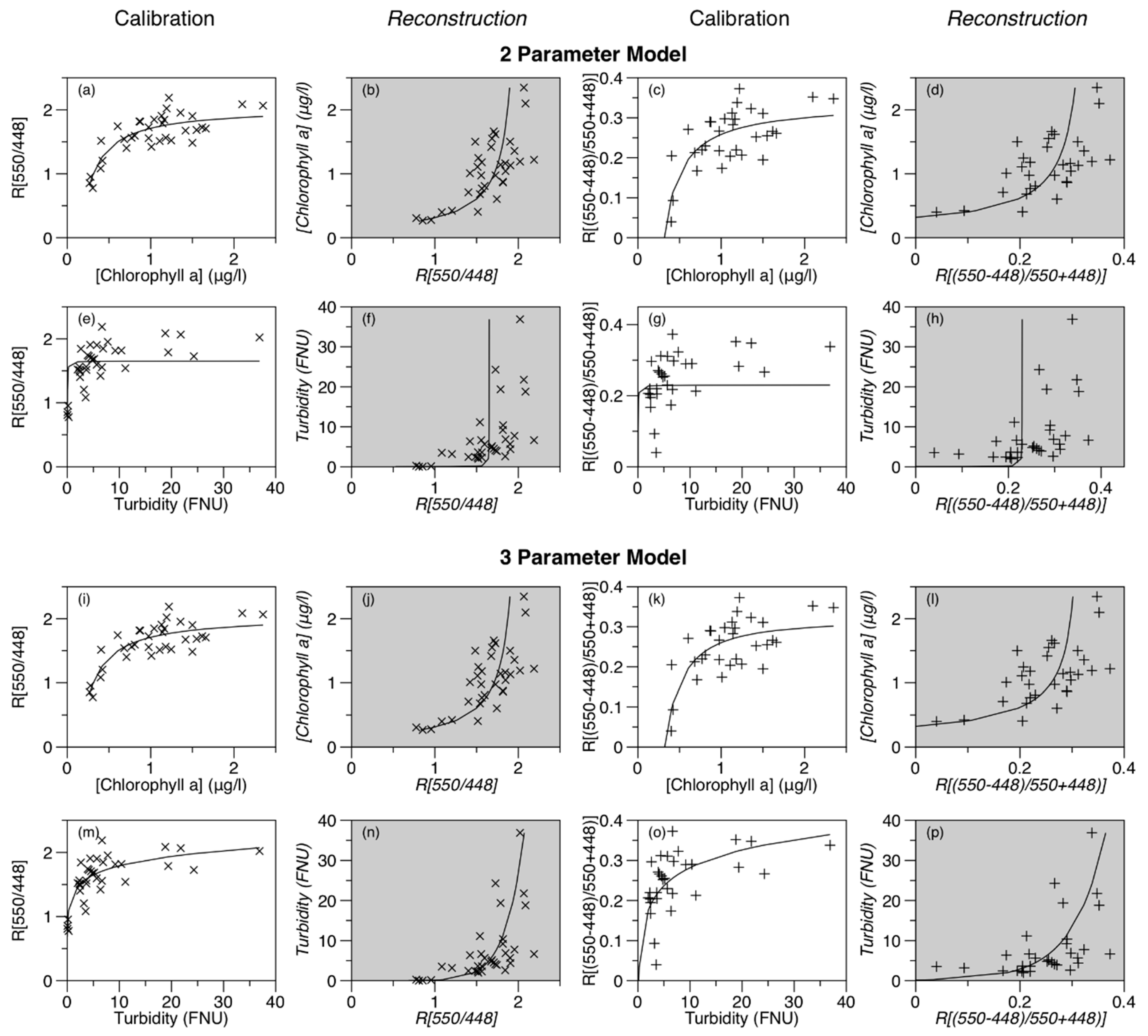
The complete results of the optimization of functions correlating calculated reflectance ratios {R(550)/R(448), R(550)/R(494), R(675)/R(448), R(675)/R(494)} or related indexes {(numerator-denominator)/(numerator+denominator)} to chlorophyll a concentration or turbidity are provided in Table 3; values for parameter estimates, their variance and their correlation matrix are presented with the percentage of variance explained by each fit, expressed as R². The best fits (represented by higher R²) were obtained in all cases with the ratio (R(550)/R(448)) and the index (R(550) − R(448))/(R(550) + R(448)); Figure 4 presents the fitted curves for these optimal cases. Regarding the case of the chlorophyll a concentration, the performances of the 2-parameter models (4 and 9) were similar to the performances of the 3-parameters models (5 and 11), i.e. fittings resulted to similar R² values. This was not the case for the turbidity for which R² doubled from the 2-parameter to the 3-parameter model fitting. It can be seen as well on Figure 4, showing that in the case of the 2-parameter turbidity model (3rd row), the curves did not fit well to the data; they were indeed characterized by a sharp increased followed by a flat curve on most of the turbidity range, hence tending to let turbidity variations being independent from the reflectance ratios and index calculations.

3.4. Calibration Results

The best fit of the 2-parameter model (Equation (10)) for the index (R(550) − R(448))/(R(550) + R(448)) was used for further calculations on [Chl-a] estimates. The 3-parameter equivalent (Equation (12)) was used for further calculations on the turbidity estimates. The best fits for the 3-parameter model was stable but the calculations of the means and the variance-covariance matrices were very unstable, due to a combination of a very high correlation between x1 and x2 (close to 1), a large dispersion of data, and the implemented bootstrap method, which theoretically requires no dependency between the error and the explanatory variable.

3.5. Model Validation

The ranges of chlorophyll a concentrations [Chl-a] were different between the 3 French sites used for validation: Site 1 in France produced the highest range in observed [Chl-a] (0.31–2.63 µg·L−1), with an average equal to 1.10 µg·L−1 (104 points). Sites 2 and 3 had smaller ranges of in-situ measured values of [Chl-a] (0.10–0.24 µg·L−1 and 0.15–0.65 µg·L−1, with averages being equal to 0.18 and 0.29 µg·L−1 for 77 and 115 points for sites 2 and 3 respectively). The calculation of the model (10) was applied to indices of reflectance measured at the French sites. The model under-estimated [Chl-a] for site 1 while overestimating values for site 3 and was quite accurate for site 2. Model results for site 1 showed the range of observed values was larger than the range of calculated values (ranging between 0.5 to 1.2 µg·L−1). It was the contrary for Site 3 (The calculated values varied between 0.3 and 2.2 µg·L−1). For site 2, the calculated values were slightly comparable in range (between 0.3 and 0.5 µg·L−1) but slightly higher in average than the observed values. For Turbidity, the values observed in France were much smaller (by almost two orders of magnitude) than values observed in the U.K., which made the validation evaluation difficult.
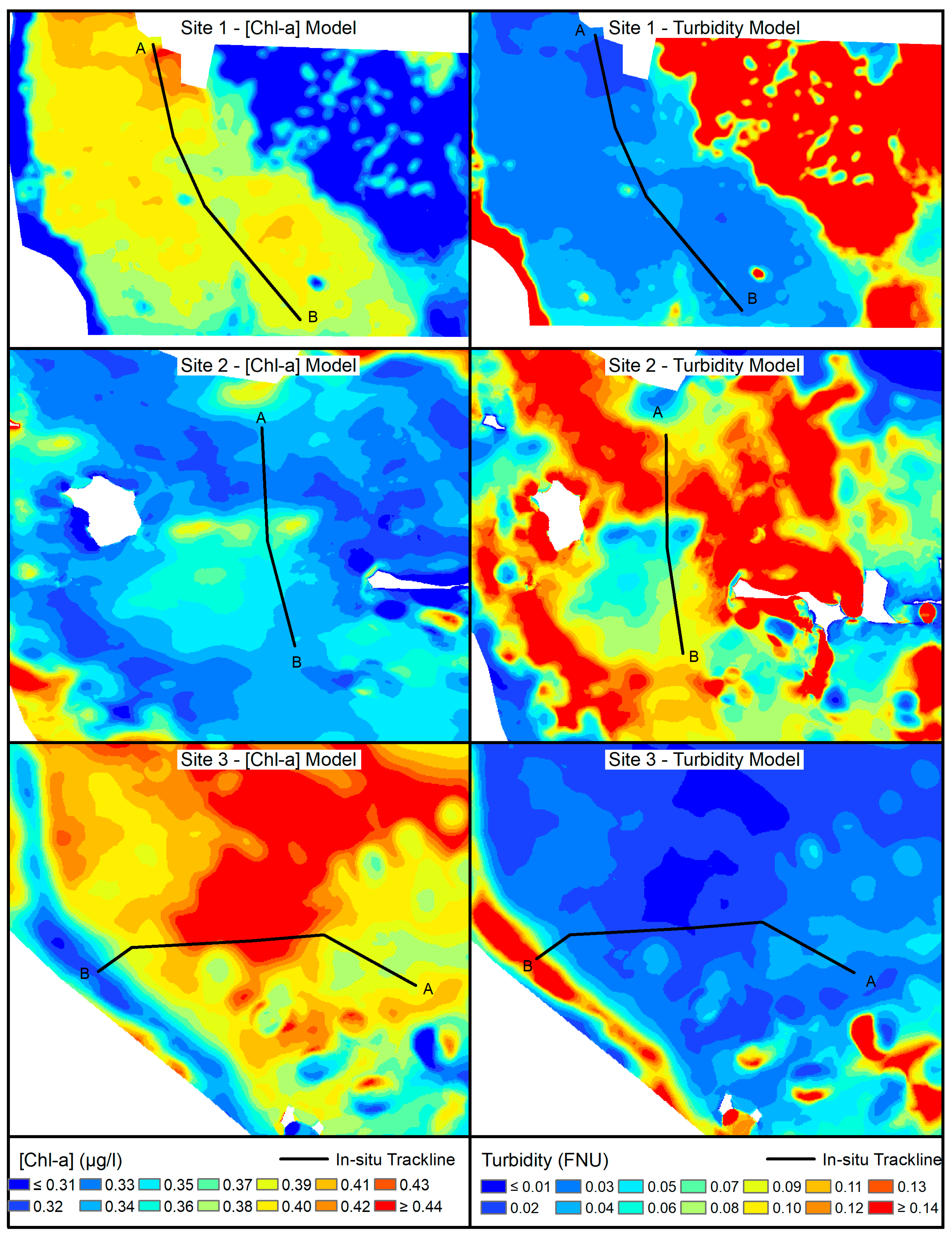
Applying inversed calibration curves of indices on the measured reflectance values led to estimates of the spatial distribution of chlorophyll a concentration and turbidity. Results are displayed in Figure 5. In the 3 cases, there is an inverse pattern of higher concentration of chlorophyll a in areas with lower turbidity. It can be seen that transects for the validation were mainly performed in areas with low turbidity.

4. Discussion

Reflectance ratios are standard proxies of environmental variables for most satellite sensor algorithms (such as OCx) while normalizing indices (such as Normalized Difference Vegetation Index, NDVI) are standard proxies of environmental variables for multispectral sensors used in the agricultural industry. Agriculture has mainly used NDVI [29] to monitor field productivity [30]. This index uses RNIR, which is the reflectance measured in a wavelength band between 0.750 nm and 1.100 nm (Near Infrared), and Rred, which is the reflectance measured in a wavelength band between 0.550 nm and 0.750 nm; NDVI is calculated as (RNIR − Rred)/(RNIR + Rred). Infrared light does not penetrate more than a meter in water masses, hence are useless for most marine applications; conversely, McKinnon and Hoff, [31] have shown that indexes based on visible spectrum, as used for water masses, cannot be applied reliably in cases of agricultural fields.
In waterbodies, there is typically stronger absorption (lower reflectance) in the lower wavelength bands, mainly centered around 448 nm (blue), but also covering a part of the 494nm wavelength band (cyan) than at 550 nm (green) and 675 nm (red). This implies that a higher reflectivity should be observed in the green and red wavebands. In addition, the minimum and maximum of reflectance in phytoplankton productive waters are around 400 nm and 550 nm respectively [32]. Our calibration results are in good agreement with the basic reflectance pattern of phytoplankton productive waters, since the best fits were achieved with a ratio and index that involved reflectance measured at wavelength bands centered around 448 nm and 550 nm. In addition, the index (R(550) − R(448))/(R(550) + R(448)) is always positive, confirming that reflectance is always higher at 550nm than at 448 nm.
The sample size used to develop the [Chl-a] algorithm was small compared to standard remote sensing studies (n = 35), but they are sufficient to produce a calibration relationship between reflectance ratios or indexes and in-situ measurements mainly for two reasons. First, to fit a 2 or 3 parameter curve requires only a minimum of 4 or 5 data points, respectively. Second, the percentage of variance explained by the fitted functions reached 78% for [Chl-a] (with a 2-parameters function) and 74% for turbidity (with a 3-parameters function). This good score is due to the fact that there are strong linear correlations between reflectance measured at any two wavelength bands; this makes the fit structurally robust. A significant non-linear correlation between multispectral measurements and in-situ turbidity measurements was found with a 3-parameters model and not with a two parameters model, suggesting that the relative distribution of the reflectance ratio or index and turbidity are skewed. This was not a problem for best parameter estimates, but the calculation of variance should be explored further since the method we implemented is sensitive to high dispersion [28].
The multispectral results from all the [Chl-a] models at the validation data at Site 1 in France revealed a “bloom” or “spike” of higher [Chl-a] that was also observed in the in-situ measurements (Figure 5). This provides strong evidence that the UAV multispectral sensors have the ability to detect changes in water quality parameters. The modeled values tend to overestimate low concentrations and underestimate high concentrations, which suggests that localized adjustments and calibrations to algorithms should be performed at each site may in order to improve [Chl-a] retrieval estimates. The poorer estimates (for sites 2 and 3) coincided with low [Chl-a] concentrations, suggesting that this technology with our methodology might be better suited for areas of higher concentrations or where large ranges in concentrations are expected.
The results from site 2 in France showed a lag in peaks of modeled and in-situ measurements. It could be explained by the time difference between the UAV survey and the in-situ measurements (approx. 30 min), together with fast changing local hydrodynamic conditions, such as induced by tides. Site 2 is located in a small estuary with a narrow channel exposed to the open ocean, and therefore changes in water quality are expected with tidal cycles. However, this explanation is weakened by the fact that correlations between simulations and observations are not significant. Overall, the distribution patterns of chlorophyll a concentration and turbidity were inversed on French sites, suggesting that production was higher in less turbid zones, but this is not in agreement with the absence of relationship that was assessed in U.K., suggesting that the link between [Chl-a] and Turbidity is complex. [Chl-a] in Site 3 in France has shown no concordance between simulations and observations. The reflectance data from this site were disturbed by the presence of shadows due to boats anchored in the bay. This artifact in the data shows up as “spots” or “bubbles” in the water quality map (site 3, Figure 5). This study did not explore the process of correcting the data biases introduced by bottom reflectance from the seabed as we determined this issue deviated too much from the initial goals of this study, which is to make an initial assessment of using multispectral sensors on UAVs to map water quality parameters.

Limitations and Future Applications

This study proposed a [Chl-a] model that can be used to detect signals and changes in water quality as seen by the results obtained from the nearshore sites in France, but localized discrepancies suggests site-specific adjustments (i.e., site-specific parameters identification) are needed. One of the major limitations for measuring water quality with UAV multispectral sensors is the issue with bottom reflectance as suggested by the results at the validation site 3. Many studies based on satellite data [33,34,35,36,37,38] have attempted to solve this problem, but there were no easy solutions proposed to remove the reflectance influence of the seabed in optically complex, shallow water environments. This issue not only will need to be addressed in future studies but requires extensive examination by many researchers in order for this application of multispectral sensor technology to be more accurate and reliable.
A comprehensive understanding of the physical and biological processes at each site is essential to grasp optical complexity of remote sensing in shallow, nearshore environments. This requires more efforts than those developed here, however, UAVs have the potential to offer benefits of low cost, high resolution data acquisition to existing and future water quality monitoring projects. This research illustrates, that to estimate water quality parameters using UAV multispectral sensors, developing site-specific algorithms or specific calibration parameters is required for surveying optically complex, nearshore waters. As Dekker, et al. [39] explains, there is no “best practice” for selecting algorithms to map water quality in optically shallow coastal waters. However, we feel that the models proposed here, based on basic properties of relationships between reflectance measurements (here strong linear correlations), are crucial steps to converge toward classes of robust models. Future studies might expand on the work presented here and not only try different algorithms for water quality estimates, but also use different sensors and experiment with different depths. This study used four wavebands to estimate water quality, 448 nm, 494 nm, 550 nm and 675 nm, and these were chosen based on common wavebands used by satellites for water quality retrievals. There is evidence that water quality estimates in very shallow waters can also be retrieved at higher wave band ranges of 700 nm–900 nm [7,18,40,41]. A specific study can be conducted making vertical profiles and estimating the vertical distribution of variables according to different combination of wavelength bands measurements.

5. Conclusions

Many technological developments are still necessary for considering the future application of water quality mapping with UAV multispectral sensors. Bottom reflectance and depth will be one of the dominating issues that should drive development of UAV multispectral imagery water quality estimations in the nearshore environment. Remote sensing studies at all scales share this problem. The ability to map water quality on a small scale would nevertheless greatly benefit impact assessment projects, including monitoring effluent from an outfall pipe, and measuring plumes from small, shallow dredging operations, or other port and harbor construction activities. Not only can a UAV be used to calculate the magnitude and spatial-temporal extents of changes in water properties in the nearshore environment, but this study illustrated that UAV mounted multispectral sensors can be used to quantify concentrations of water quality parameters as well. This study does not however, conclude that the UAV multispectral system can be used as a standalone monitoring solution, but it has shown that they can improve existing and future nearshore water quality monitoring projects in conjunction with the use of in-situ instruments.
This study attempted to measure water quality from UAV multispectral sensors using the technology that was developed originally for the agriculture industry and applied methods adapted from satellite remote sensing applications. Both fields have had decades to develop technology, tools, and methods tailored to the specific application. As the applications of UAV multispectral water quality mapping grows, so will the technology and ad hoc methods. Development is completely driven by the need for better cost-effective tools to monitor water quality. UAV multispectral sensors have the potential to collect many acres of data in the nearshore environment from a single 20-min UAV flight. This study provides a foundation to begin the development of a potentially powerful tool for environmental scientists.

Author Contributions

Conceptualization, R.M., S.H.; methodology, R.M., S.H.; validation, R.M., J.-M.G.; formal analysis, R.M.; investigation, R.M.; resources, S.H.; data curation, R.M.; writing—original draft preparation, R.M.; writing—review and editing, R.M., S.H., J.-M.G., J.C.-G.; visualization, R.M.; funding acquisition, S.H. All authors have read and agreed to the published version of the manuscript.

Funding

This research was funded by Gravity Marine LLC, Fall City, Washington, USA.

Acknowledgments

The authors would like to thank Anna Hickman and Mark Moore at the University of Southampton, for not only advising on the development and analysis of this project but for providing the opportunity to collect the offshore data in this study during a research cruise. The Authors would also like to thank Jeffery Wilson at Gravity Marine for providing technical expertise during this project.

Conflicts of Interest

The authors declare no conflict of interest.

References

  1. Smith, V.H. Eutrophication of Freshwater and Coastal Marine Ecosystems a Global Problem. Environ. Sci. Pollut. Res. 2003, 10, 126–139. [Google Scholar] [CrossRef] [PubMed]
  2. Chelsea Nagy, R.; Graeme Lockaby, B.; Kalin, L.; Anderson, C. Effects of Urbanization on Stream Hydrology and Water Quality: The Florida Gulf Coast. Hydrol. Process. 2012, 26, 2019–2030. [Google Scholar] [CrossRef]
  3. Schoonover, J.E. Channel Morphology and Sediment Origin in Streams Draining the Georgia Piedmont. J. Hydrol. 2007, 342, 110–123. [Google Scholar] [CrossRef]
  4. European Union. Directive 2008/56 edited by of the European Parliament and of the Council of 17 June 2008. In Official Journal of the European Union 164/136; European Union: Brussels, Belgium, 2008. [Google Scholar]
  5. Doxaran, D.; Froidefond, J.M.; Lavender, S.; Castaing, P. Spectral Signature of Highly Turbid Waters: Application with Spot Data to Quantify Suspended Particulate Matter Concentrations. Remote Sens. Environ. 2002, 81, 149–161. [Google Scholar] [CrossRef]
  6. Novoa, S.; Chust, G.; Valencia, V.; Froidefond, J.M.; Morichon, D. Estimation of Chlorophyll-a Concentration in Waters over the Continental Shelf of the Bay of Biscay: A Comparison of Remote Sensing Algorithms. Int. J. Remote Sens. 2011, 32, 8349–8371. [Google Scholar] [CrossRef]
  7. Odermatt, D.; Gitelson, A.; Brando, V.E.; Schaepman, M. Review of Constituent Retrieval in Optically Deep and Complex Waters from Satellite Imagery. Remote Sens. Environ. 2012, 118, 116–126. [Google Scholar] [CrossRef] [Green Version]
  8. Ouillon, S.; Petrenko, A.A. Above-Water Measurements of Reflectance and Chlorophyll-a Algorithms in the Gulf of Lions, Nw Mediterranean Sea. Opt. Express 2005, 13, 2531–2548. [Google Scholar] [CrossRef]
  9. O’Reilly, J.E.; Maritorena, S.; Mitchell, B.G.; Siegel, D.A.; Carder, K.L.; Garver, S.A.; Kahru, M.; McClain, C. Ocean Color Chlorophyll Algorithms for Seawifs. J. Geophys. Res. Ocean. 1998, 103, 24937–24953. [Google Scholar] [CrossRef] [Green Version]
  10. Kirk, J.T.O. Light and Photosynthesis in Aquatic Ecosystems; Cambridge University Press: Cambridge, UK, 1994. [Google Scholar]
  11. Moses, W.J.; Gitelson, A.A.; Perk, R.L.; Gurlin, D.; Rundquist, D.C.; Leavitt, B.C.; Barrow, T.M.; Brakhage, P. Estimation of Chlorophyll-a Concentration in Turbid Productive Waters Using Airborne Hyperspectral Data. Water Res. 2012, 46, 993–1004. [Google Scholar] [CrossRef] [Green Version]
  12. Palmer, S.C.; Kutser, T.; Hunter, P.D. Remote Sensing of Inland Waters: Challenges, Progress and Future Directions. Remote Sens. Environ. 2015, 157, 1–8. [Google Scholar] [CrossRef] [Green Version]
  13. Flynn, K.F.; Chapra, S.C. Remote Sensing of Submerged Aquatic Vegetation in a Shallow Non-Turbid River Using an Unmanned Aerial Vehicle. Remote Sens. 2014, 6, 12815–12836. [Google Scholar] [CrossRef] [Green Version]
  14. Hardin, P.; Jensen, R. Small-Scale Unmanned Aerial Vehicles in Environmental Remote Sensing: Challenges and Opportunities. GIScience Remote Sens. 2011, 48, 99–111. [Google Scholar] [CrossRef]
  15. Anderson, K.; Gaston, K.J. Lightweight Unmanned Aerial Vehicles Will Revolutionize Spatial Ecology. Front. Ecol. Environ. 2013, 11, 138–146. [Google Scholar] [CrossRef] [Green Version]
  16. Kageyama, Y.; Takahashi, J.; Nishida, M.; Kobori, B.; Nagamoto, D. Analysis of Water Quality in Miharu Dam Reservoir, Japan, Using Uav Data. IEEJ Trans. Electr. Electron. Eng. 2016, 11, S183–S185. [Google Scholar] [CrossRef]
  17. Su, T.C.; Chou, H.T. Application of Multispectral Sensors Carried on Unmanned Aerial Vehicle (Uav) to Trophic State Mapping of Small Reservoirs: A Case Study of Tain-Pu Reservoir in Kinmen, Taiwan. Remote Sens. 2015, 7, 10078–10097. [Google Scholar] [CrossRef] [Green Version]
  18. Su, T.C. A Study of a Matching Pixel by Pixel (Mpp) Algorithm to Establish an Empirical Model of Water Quality Mapping, as Based on Unmanned Aerial Vehicle (Uav) Images. Int. J. Appl. Earth Obs. Geoinf. 2017, 58, 213–224. [Google Scholar] [CrossRef]
  19. Cillero Castro, C.; Domínguez Gómez, J.A.; Delgado Martín, J.; Hinojo Sánchez, B.A.; Cereijo Arango, J.L.; Cheda Tuya, F.A.; Díaz-Varela, R. An Uav and Satellite Multispectral Data Approach to Monitor Water Quality in Small Reservoirs. Remote Sens. 2020, 12, 1514. [Google Scholar] [CrossRef]
  20. Klemas, V.V. Coastal and Environmental Remote Sensing from Unmanned Aerial Vehicles: An Overview. J. Coast. Res. 2015, 31, 1260–1267. [Google Scholar] [CrossRef] [Green Version]
  21. Zang, W.; Lin, J.; Wang, Y.; Tao, H. Investigating Small-Scale Water Pollution with Uav Remote Sensing Technology. In World Automation Congress; Puerto Vallarta, Mexico, 2012; pp. 1–4. Available online: https://www.semanticscholar.org/paper/Investigating-small-scale-water-pollution-with-UAV-Zang-Lin/767fa8b350ee6fbb79cc121da625722b012bcf59 (accessed on 12 June 2020).
  22. Yang, C. A High-Resolution Airborne Four-Camera Imaging System for Agricultural Remote Sensing. Comput. Electron. Agric. 2012, 88, 13–24. [Google Scholar] [CrossRef]
  23. Welschmeyer, N.A. Fluorometric Analysis of Chlorophyll a in the Presence of Chlorophyll B and Pheopigments. Limnol. Oceanogr. 1994, 39, 1985–1992. [Google Scholar] [CrossRef]
  24. Brown, M.; Lowe, D.G. Automatic Panoramic Image Stitching Using Invariant Features. Int. J. Comput. Vis. 2007, 74, 59–73. [Google Scholar] [CrossRef] [Green Version]
  25. Song, H.; Yang, C.; Zhang, J.; Hoffmann, W.C.; He, D.; Thomasson, J.A. Comparison of Mosaicking Techniques for Airborne Images from Consumer-Grade Cameras. J. Appl. Remote Sens. 2016, 10, 1–14. [Google Scholar] [CrossRef] [Green Version]
  26. Frouin, R.; Lingner, D.W.; Gautier, C.; Baker, K.S.; Smith, R.C. A Simple Analytical Formula to Compute Clear Sky Total and Photosynthetically Available Solar Irradiance at the Ocean Surface. J. Geophys. Res. Ocean. 1989, 94, 9731–9742. [Google Scholar] [CrossRef]
  27. Nelder, J.A.; Mead, R. A Simplex Method for Function Minimization. Comput. J. 1965, 7, 308–313. [Google Scholar] [CrossRef]
  28. Efron, B. Bootstrap Methods: Another Look at the Jackknife. Ann. Statist. 1979, 7, 1–26. [Google Scholar] [CrossRef]
  29. Tucker, C.J. Red and Photographic Infrared Linear Combinations for Monitoring Vegetation. Remote Sens. Environ. 1979, 8, 127–150. [Google Scholar] [CrossRef] [Green Version]
  30. ITU. Drones for Agriculture: E-Agriculture in Action; ITU: Geneva, Switzerland, 2018; Available online: http://handle.itu.int/11.1002/pub/8111728e-en (accessed on 14 May 2020).
  31. McKinnon, T.; Hoff, P. Comparing Rgb-Based Vegetation Indices with Ndvi for Drone Based Agricultural Sensing. Agribotix. Com. 2017, 21, 1–8. Available online: https://agribotix.com/wp-content/uploads/2017/05/Agribotix-VARI-TGI-Study.pdf (accessed on 12 June 2020).
  32. Metsamaa, L.; Kutser, T.; Strömbeck, N. Recognising Cyanobacterial Blooms Based on Their Optical Signature: A Modelling Study. Boreal Environ. Res. 2006, 11, 493–506. [Google Scholar]
  33. Cannizzaro, J.P.; Carder, K.L. Estimating Chlorophyll a Concentrations from Remote-Sensing Reflectance in Optically Shallow Waters. Remote Sens. Environ. 2006, 101, 13–24. [Google Scholar] [CrossRef]
  34. Minghelli-Roman, A.; Dupouy, C. Influence of Water Column Chlorophyll Concentration on Bathymetric Estimations in the Lagoon of New Caledonia, Using Several Meris Images. IEEE J. Sel. Top. Appl. Earth Obs. Remote Sens. 2013, 6, 739–745. [Google Scholar] [CrossRef] [Green Version]
  35. Wattelez, G.; Dupouy, C.; Mangeas, M.; Lefèvre, J.; Frouin, R. A Statistical Algorithm for Estimating Chlorophyll Concentration in the New Caledonian Lagoon. Remote Sens. 2016, 8, 45. [Google Scholar] [CrossRef] [Green Version]
  36. Minghelli-Roman, A.; Dupouy, C. Correction of the Water Column Attenuation: Application to the Seabed Mapping of the Lagoon of New Caledonia Using Meris Images. IEEE J. Sel. Top. Appl. Earth Obs. Remote Sens. 2014, 7, 2619–2629. [Google Scholar] [CrossRef] [Green Version]
  37. Schaeffer, B.A.; Hagy, J.D.; Conmy, R.N.; Lehrter, J.C.; Stumpf, R.P. An Approach to Developing Numeric Water Quality Criteria for Coastal Waters Using the Seawifs Satellite Data Record. Environ. Sci. Technol. 2012, 46, 916–922. [Google Scholar] [CrossRef] [PubMed]
  38. Barnes, B.B.; Hu, C.; Schaeffer, B.A.; Lee, Z.; Palandro, D.A.; Lehrter, J.C. Modis-Derived Spatiotemporal Water Clarity Patterns in Optically Shallow Florida Keys Waters: A New Approach to Remove Bottom Contamination. Remote Sens. Environ. 2013, 134, 377–391. [Google Scholar] [CrossRef] [Green Version]
  39. Dekker, A.G.; Phinn, S.R.; Anstee, J.; Bissett, P.; Brando, V.E.; Casey, B.; Fearns, P.; Hedley, J.; Klonowski, W.; Lee, Z.P.; et al. Intercomparison of Shallow Water Bathymetry, Hydro-Optics, and Benthos Mapping Techniques in Australian and Caribbean Coastal Environments. Limnol. Oceanogr. Methods 2011, 9, 396–425. [Google Scholar] [CrossRef] [Green Version]
  40. Nechad, B.; Ruddick, K.G.; Neukermans, G. Calibration and Validation of a Generic Multisensor Algorithm for Mapping of Turbidity in Coastal Waters. In Proceedings of the SPIE—The International Society for Optical Engineering, Berlin, Germany, 9 September 2009; p. 7473. [Google Scholar]
  41. Binding, C.E.; Jerome, J.H.; Bukata, R.P.; Booty, W.G. Suspended Particulate Matter in Lake Erie Derived from Modis Aquatic Colour Imagery. Int. J. Remote Sens. 2010, 31, 5239–5255. [Google Scholar] [CrossRef]
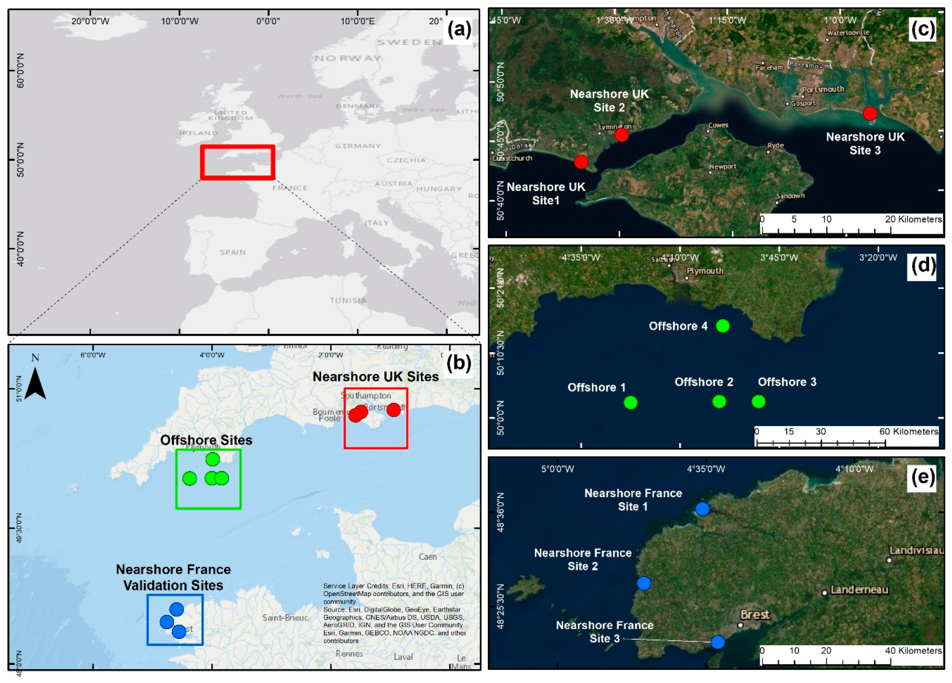
Figure 1. Geographical distribution of the sampling sites (a) Overview of the study area on the coasts of the English Channel, Europe. (b) The 3 main areas where datasets were collected in this study. (c) Three nearshore sites in the U.K. (d) Four offshore sites in the U.K. (e) Three nearshore sites in France, used as independent validation dataset for this study.
Remotesensing 12 02258 g001
Figure 2. Relationships between reflectance measurements performed at different wavelength bands {448 nm (blue), 494 nm (cyan), 550 nm (green), 675 nm (red)} and environmental variables. From left to right and top to down are represented Reflectance values (in %) as a function of (a) Temperature (°C), (b) Salinity (psu), (c) Turbidity (FNU), (d) Chlorophyll a concentration (µg·L−1) and (e) Incident light (W·m−2). The last figure ((f), lower-right) shows the relationship between Turbidity and Chlorophyll a concentration. Linear regressions did not exhibit slopes significantly different from zero (t-tests, d.o.f. = 33, p = 0.05), suggesting both low dependencies and large dispersion of the data.
Remotesensing 12 02258 g002
Figure 3. Orthogonal linear regressions between reflectance measurements performed at different wavelength band combinations using 448 nm, 494 nm, 550 nm and 675 nm respectively, (af). The regression line is represented by the solid lines and the line y = x (first bisector) is represented by the dashed lines. Parameters (slope and intersect), along with the respective determination coefficients (R²) are provided for all graphs (a to f) in Table 2.
Remotesensing 12 02258 g003
Figure 4. Calibration functions linking [Chl-a] and Turbidity to reflectance ratios and indexes calculated from reflectance measured at λ = 448 nm and λ = 550 nm. From left to right: calibration curve for the R(550)/R(448) ratio, the inversed curve to reconstruct chlorophyll a concentration and Turbidity from the reflectance ratio (grey background), calibration curve for (R(550) − R448)/(R550 + R(448)) index and inversed curve to reconstruct chlorophyll a concentration and Turbidity from the reflectance index (grey background). From top to down, Fit of the 2-parameters functions involving [Chl-a] (ad) and turbidity (eh) as explanatory variable, fit of the 3-parameters functions involving [Chl-a] (il) and turbidity (mp) as explanatory variable.
Remotesensing 12 02258 g004
Figure 5. Spatial distribution of the chlorophyll a concentration [Chl-a] (left column) and turbidity (right column) calculated from the multispectral imagery collected from the UAV at the validation sites in France, using inversed calibration function parameterized for UK sites: [Chl-a] was calculated using the 2-parameter index equation (Equation (10)) and turbidity was calculated using the 3-parameter index equation (Equation (12)). The solid black lines show the track of the in-situ measurements collected with the EXO-1 sensor towed by a boat, beginning at A and finishing at B.
Remotesensing 12 02258 g005
Table 1. Wavelength bands used to measure reflectance with the multispectral sensor installed on the UAV used in this study. Wavelength bands were limited to the visible light (λ between 400 and 700 nm) since UV (λ < 400 nm) and infrared (λ > 700 nm) bands are strongly absorbed by water, and not preferable to infer water quality indicators.
ColorCenter Wavelength (nm)Wavelength Range (nm)
Blue448438.0–458.0
Blue494484.0–504.0
Green550537.5–652.5
Red675662.5–687.5
Table 2. Band value comparison from the in-situ data collected with all 4 multispectral sensors from orthogonal regression taking wavelength bands 2 by 2 and providing slope, intercept and (R2). The corresponding plots in Figure 2 are indicated for references.
Plot in Figure 2λ1 (nm)λ2 (nm)SlopeInterceptR2
a4484941.170.130.86
b4485501.60−0.080.86
c4486751.33−0.540.86
d4945501.40−0.400.73
e4946751.29−1.350.69
f5506750.92−1.000.96
Table 3. Parameter estimates for the calibration models (2 and 3 parameters) applied to the Reflectance ratios and indexes, as functions of concentration of chlorophyll a concentration (µg·L−1) and Turbidity (FNU). Between brackets are ratios or indices combining reflectance measured at 4 different wavelength bands centered on 448, 494, 550 and 675 nm. Mean and covariance were calculated from 200 bootstrap pseudo-replicates.
[Chl-a] (2 parameters)[550/448][(550 − 448)/(550 + 448)][675/448][(675 − 448)/675 + 448)][550/494][(550 − 494)/(550 + 494)][675/494][(675 − 494)/675 + 494)]
Best(x1)2.032.021.531.501.671.691.261.25
Best(x2)−0.32−0.32−0.28−0.27−0.26−0.28−0.23−0.23
0.700.780.650.650.680.740.600.61
Mean(x1)2.032.021.531.511.681.691.251.24
Mean(x2)−0.32−0.32-0.29−0.28−0.27−0.28−0.23−0.23
Var(x1)0.000.000.000.000.000.000.000.00
Var(x2)0.000.000.000.000.000.000.000.00
Corr(x1,x2)−0.84−0.87−0.83−0.84−0.77−0.82−0.85−0.87
[Chl-a] (3 parameters)[550/448][(550 − 448)/(550 + 448)][675/448][(675 − 448)/675 + 448)][550/494][(550 − 494)/(550 + 494)][675/494][(675 − 494)/675 + 494)]
Best(x1)2.051.932.261.701.551.501.451.25
Best(x2)−0.34−0.17−1.04−0.44−0.13−0.07−0.43−0.24
Best(x3)0.971.490.380.981.482.090.651.25
0.700.780.670.660.690.750.600.61
Mean(x1)2.291.962.532.441.631.531.751.51
Mean(x2)−0.59−0.19−1.29−1.11−0.21−0.09−0.73−0.50
Mean(x3)1.041.560.591.041.562.110.791.35
Var(x1)0.840.032.9410.060.190.011.231.49
Var(x2)0.860.022.968.780.200.011.271.57
Var(x3)0.260.200.150.250.400.360.210.32
Corr(x1,x2)−1.00−0.97−1.00−1.00−1.00−0.91−1.00−1.00
Corr(x1,x3)−0.61−0.83−0.60−0.39−0.46−0.75−0.60−0.45
Corr(x2,x3)0.620.870.610.390.480.840.610.45
Turbidity (2 parameters)[550/448][(550 − 448)/(550 + 448)][675/448][(675 − 448)/675 + 448)][550/494][(550 − 494)/(550+494)][675/494][(675 − 494)/675 + 494)]
Best(x1)1.651.601.191.121.361.320.980.94
Best(x2)−0.02−0.02−0.02−0.01−0.01−0.01−0.01−0.01
0.310.340.250.250.190.150.170.14
Mean(x1)1.661.591.191.111.361.320.990.93
Mean(x2)−0.02−0.02−0.02−0.01−0.01−0.01−0.01−0.01
Var(x1)0.000.000.000.000.000.000.000.00
Var(x2)0.000.000.000.000.000.000.000.00
Corr(x1,x2)−0.17−0.46−0.18−0.42−0.31−0.41−0.29−0.38
Turbidity (3 parameters)[550/448][(550 − 448)/(550+448)][675/448][(675 − 448)/675+448)][550/494][(550 − 494)/(550+494)][675/494][(675 − 494)/675+494)]
Best(x1)−2.25−2.26−1.56−1.08−8.82−1.20−13.83−1.00
Best(x2)3.593.102.502.089.982.1914.652.00
Best(x3)−0.050.03−0.060.00−0.010.01−0.010.00
0.680.740.560.580.510.530.410.44
Mean(x1)−1.41−4.19−0.86−1.20−1.17-1.59−2.53−1.00
Mean(x2)2.734.761.782.212.302.563.312.00
Mean(x3)−0.110.02−0.140.00−0.130.00−0.170.00
Var(x1)6.4977.142.921.088.395.7827.020.00
Var(x2)6.5157.832.931.218.455.2127.230.00
Var(x3)0.000.000.010.000.010.000.020.00
Corr(x1,x2)−1.00−1.00−1.00−1.00−1.00−1.00−1.00−1.00
Corr(x1,x3)−0.70−0.64-0.68−0.58−0.61−0.53−0.65−0.74
Corr(x2,x3)0.700.640.680.590.610.530.640.73