Article

Falling Mixed-Phase Ice Virga and their Liquid Parent Cloud Layers as Observed by Ground-Based Lidars

1
School of Electronic Information, Wuhan University, Wuhan 430072, China
2
Key Laboratory of Geospace Environment and Geodesy, Ministry of Education, Wuhan 430072, China
3
State Observatory for Atmospheric Remote Sensing, Wuhan 430072, China
*
Author to whom correspondence should be addressed.
Remote Sens. 2020, 12(13), 2094; https://doi.org/10.3390/rs12132094
Submission received: 15 May 2020 / Revised: 24 June 2020 / Accepted: 24 June 2020 / Published: 30 June 2020
(This article belongs to the Special Issue Remote Sensing of Clouds)

Abstract

:
Falling mixed-phase virga from a thin supercooled liquid layer cloud base were observed on 20 occasions at altitudes of 2.3–9.4 km with ground-based lidars at Wuhan (30.5 °N, 114.4 °E), China. Polarization lidar profile (3.75-m) analysis reveals some ubiquitous features of both falling mixed-phase virga and their liquid parent cloud layers. Each liquid parent cloud had a well-defined base height where the backscatter ratio R was ~7.0 and the R profile had a clear inflection point. At an altitude of ~34 m above the base height, the depolarization ratio reached its minimum value (~0.04), indicating a liquid-only level therein. The thin parent cloud layers tended to form on the top of a broad preexisting aerosol/liquid water layer. The falling virga below the base height showed firstly a significant depolarization ratio increase, suggesting that most supercooled liquid drops in the virga were rapidly frozen into ice crystals (via contact freezing). After reaching a local maximum value of the depolarization ratio, both the values of the backscatter ratio and depolarization ratio for the virga exhibited an overall decrease with decreasing height, indicating sublimated ice crystals. The diameters of the ice crystals in the virga were estimated based on an ice particle sublimation model along with the lidar and radiosonde observations. It was found that the ice crystal particles in these virga cases tended to have smaller mean diameters and narrower size distributions with increasing altitude. The mean diameter value is 350 ± 111 µm at altitudes of 4–8.5 km.

Graphical Abstract

1. Introduction

Clouds can exhibit the essential structure of a weather system (such as frontal cloud system), sometimes providing a precursor for local precipitation [1]. Clouds are also an important part of the Earth’s climate system [2]. They regulate the balance of earth’s energy budget [3,4] in a complicated way. However, it is currently difficult to make accurate numerical cloud predictions [5]. A main reason for this situation is a considerable lack of observation-based process-level understanding on the formation, growth and phase transition of atmospheric water particles (liquid droplets and ice crystals) as well as production of precipitation. In fact, since the real cloud processes involve the complex interplay of water vapor/aerosol, atmospheric dynamics and cloud microphysical properties [6], it is actually a challenge to identify and/or isolate a fundamental process leading to cloud formation and growth from observational data [7]. Meanwhile, some microphysical processes involved in cloud and precipitation are too swift to be resolved by conventional instruments (lidar, radar and airborne in situ measurements). In addition, once a cloud has formed, significant cloud attenuation often limits an effective measurement on the in-cloud processes with ground-based lidar and radar. Therefore, at present, the observational investigations focusing on some condition-simple and detectable cloud phenomena that may facilitate unraveling the practical cloud processes.
Liquid-layer-topped ice virga have been extensively used to study ice formation process because ground-based lidar and radar can reliably detect the entire height range of ice virga and their parent cloud base [8,9,10,11,12]. It is found that in the stratiform cloud layers at temperatures above −20 °C, bulk ice particles (ice virga) occurred below after the bulk liquid phase had formed overhead [10,13,14]. It is suggested that ice heterogeneous nucleation proceeds via the freezing of supercooled droplets [14,15]. The majority of ice crystals falling from the liquid parent cloud bases are mostly pristine [11]. The observations also reveal that the vertical-air-velocity standard deviation at the parent cloud base has a strong impact on the ice formation rate as the cloud-top temperature is below −12 °C [7].
Supercooled (<0 °C) liquid water droplets are widespread in the middle tropospheric clouds [16,17,18]. They are in metastable state and susceptible to a transition to ice phase by external disturbances [19]. According to laboratory experiments, the freezing process of a supercooled water droplet must go through two stages [20]. In the first stage, the droplet temperature spontaneously rises to an equilibrium freezing temperature in tens of milliseconds [21]. In the second stage, the freezing occurs initially at the surface of the droplet (yielding a frozen shell) and then propagates inwardly. The second stage takes ~10–100 s [22]. Laboratory experiments show also that a supercooled drop larger than 100 µm in diameter may remain spherical or quasi-spherical during the freezing process [23]. The freezing of droplets with different sizes has been experimentally examined. It is shown that the larger droplets have higher freezing temperatures than the smaller ones [24].
Although the field observations and laboratory experiment studies have provided significant knowledge on the microphysical properties of the frozen droplets, the microphysical processes on the supercooled water droplets freezing in the stratiform clouds are currently not well understood [25,26]. This calls for further observational investigations. The liquid-layer-topped ice virga have been observed occasionally by ground-based lidars at Wuhan (30.5 °N, 114.4 °E), China. The evolution of hydrometeors falling from the liquid parent cloud has been re-examined by analyzing the sequence of the 3.75-m polarization lidar profiles. This paper describes first the relevant instrumentation and methodology. Section 3 presents two examples of the liquid-layer-topped ice virga observed by our lidars and relevant calculation. The discussion and conclusion are given in Section 4 and Section 5, respectively.

2. Instrumentation and Methodology

2.1. Lidar

Aerosol and cloud observations were conducted with two co-located lidars at the Wuhan University atmospheric observation site (30.5 °N, 114.4 °E, 80 m above sea level). Two lidar can simultaneously deliver the sequential profiles of the backscatter ratio, volume depolarization and water vapor mixing ratio. All of the observation sessions started with clear-sky conditions and ended when heavy precipitations occurred. This allowed us to capture liquid-layer-topped ice virga present at our mid-latitude site.

2.1.1. Polarization Lidar

Wuhan University polarization lidar and its performance have been described in detail by [27], and therefore, only a brief introduction of the lidar system together with its application to the identification of liquid and ice clouds is given here. The lidar transmitter employs a frequency-doubled Nd:YAG laser to produce an emission of ~120 mJ per pulse at 532 nm with a repetition rate of 20 Hz. A Brewster polarizer is added to improve the polarization purity of the transmitting laser (up to ~10000:1). After beam expansion, the beam with a divergence of 0.75 mrad is transmitted vertically into the atmosphere. The backscattered light is collected by a 30-cm Cassegrain telescope. The receiver field of view (FOV) is 1 mrad, which is favorable for reducing the effect of multiple scattering on lidar echo signal. After collimated, the elastically backscattered light passes an interference filter (0.3 nm bandwidth centered at 532 nm) and then incidents a polarization beam splitter prism (PBS). In order to decrease the cross talk between the two orthogonal polarization channels, two additional polarizers are placed respectively on two output sides of the PBS. The light exiting from the two polarizers is respectively focused onto two photomultiplier tubes (PMTs). The signals from the two PMTs are gathered by a PC-controlled two-channel transient digitizer (TR40–160, manufactured by Licel).
The raw lidar data were stored with a range resolution of 3.75 m and temporal resolution of 1 min. The coarser resolution was acquired simply by an integration over several bins. The lidar observation lower limit was 0.3 km, which was determined based on the overlap of the laser and the field of view of the telescope. The volume depolarization ratio δ, defined by the ratio of the perpendicular- to the parallel-polarized backscatter coefficients, can be obtained from the two-channel lidar signals along with the relative gain of the parallel and perpendicular channels. The relative gain is determined in advance using a method described by [28]. The magnitude of δ value allows us to identify whether the dominant backscattering comes from ice crystals or water droplets in a given backscatter volume [29]. Liquid water droplets suspended in the atmosphere are nearly spherical that produce a very low depolarization ratio (close to zero) for single scattering at exactly 180°, while ice crystals, usually nonspherical, generate a quite large depolarization ratio in the 180° backscattering direction. Consequently, in this study, the discrimination criteria in terms of the depolarization ratio magnitude are δ < 0.1 for water droplets and δ > 0.2 for ice crystals, respectively [30,31].
The backscatter ratio R is defined as a ratio of the sum of aerosol and molecular backscatter coefficients to the molecular one. R can be retrieved from the lidar data by the Fernald-Klett backward iteration method with an assumed lidar ratio and a reference altitude where the particulate backscatter coefficient is negligible [32]. In the presence of clouds, it is hard to find a reference altitude above cloud due to a strong cloud attenuation. In this case, a reference altitude below cloud has to be chosen and thus the Fernald-Klett forward iteration method needs to be used. With respect to the lidar ratio, two fixed values of 40 and 20 sr [33] were utilized in our retrieval respectively for the aerosol/liquid water layer and liquid water cloud. In order to distinguish whether a lidar-observed layer is an aerosol/liquid layer or a cloud layer, the authors of [34] introduced a ratio of the lidar signals at the layer peak and base. The layers with the peak-to-base ratio greater than 4.0 were registered as cloud layers [35]. According to a previous study [36], we set a similar experiential cloud criterion in terms of the retrieved backscatter ratio. The layers with R > 7.0 are called “cloud”, while those with R < 7.0 are categorized as “aerosol layer”.

2.1.2. Water Vapor Raman Lidar

The Raman lidar was built to measure the profiles of the water vapor mixing ratio (WVMR) at our site. It transmits laser pulses with ~150 mJ at 355 nm with a repetition rate of 20 Hz, and receives inelastic Raman backscatter signal from water vapor at 407 nm and nitrogen at 387 nm as well as elastic backscattered light using a 45 cm receiver telescope. The WVMR, which is defined as the mass ratio between water vapor and dry air in a given volume, can be obtained from the Raman signals of water vapor and nitrogen molecules [37]. The Raman lidar system was calibrated by accompanying local radiosonde measurements. A comparison showed that the lidar-derived water vapor mixing ratio profiles agree well with the coincident radiosonde data (the relative deviation is less than 10% when the water vapor field is horizontally homogeneous on a scale of ~20 km). During daytime, the water vapor Raman signal was very noisy due to strong sky background light so that the water vapor mixing ratio profiles became unavailable.

2.2. Radiosonde

The radiosondes (GTS1-2) made by China are launched daily at 0000 UTC (0800 LT) and 1200 UTC (2000 LT) from Wuhan Weather Station (~23.4 km away from our lidar site). Profiles of air pressure, temperature, relative humidity, wind speed, and direction from near surface up to 20–30 km height are measured. The individual temperature and relative humidity profiles from the radiosondes are used to determine the meteorological conditions for the liquid-layer-topped ice virga. Their temperature measurement error is less than 1°C, and uncertainty in the relative humidity measurement is less than 5% when temperature is higher than −10°C [38].

2.3. FY-2E

FY-2E was successfully launched by a long march-3a carrier rocket from Xichang Satellite Launch Center on December 23, 2008 [39]. FY-2E was positioned above the Equator at 105 degrees East longitude in February 2009, and it has been drifting to 86.5 degrees East longitude since 1 July 2015, providing observation services. Cloud classification (CLC) products are processed based on FY-2E cloud image data, including types such as ground, sea, stratocumulus, cirrus and cumulonimbus. CLC products can provide an hourly cloud image with a coverage range of East longitude 55 degrees to 155 degrees, latitude 55 degrees North to 45 degrees South and a resolution of 5 km per hour. CLC images are mainly used to help us understand the spatial scale of clouds in our observational cases.

2.4. Methodology

To estimate the vertical profile of ice crystals diameter in the virga, we can examine the diameter (mass) change of a falling ice particle by considering only a sublimation process (neglecting the effect of turbulence [40] and collision process between falling ice crystals and water droplets). The rate of mass change of an ice crystal particle via condensation/sublimation process is governed by the following expression [22]:
d m d t = 4 π C i Δ S i G i ( T , p ) f i v ( R e )
where m is the ice crystal mass, C i is the crystal capacitance term, Δ S i = S i 1 is the supersaturation/subsaturation with respect to ice. G i ( T , p ) = [ L i κ a T ( L i R V T 1 ) + R V T D V e s i ( T ) ] - 1 is the thermodynamic function, in which L i is the sublimation latent heat, κ a is the thermal conductivity of air, R V is specific gas constant for water vapor, D V is the diffusion coefficient or diffusivity of water vapor, e s i ( T ) is the saturation water vapor pressure over ice, T is the environmental temperature, respectively. f i v ( R e ) = 0 . 78 + 0 . 275 R e 1 / 2 is the ventilation coefficient given in [41], in which R e is the Reynolds number. Assuming that the ice crystal particles detected by the lidar is near-spherical ( m = π D 3 ρ i / 6 ), the capacitance term is C i = D / 2 (D denotes the diameter for ice particle) [42,43]. With this assumption and Equation (1), the change of ice particle radius with altitude due to vapor sublimation can be expressed as:
D v i d D d z = 4 ρ i - 1 Δ S i G i ( T , p ) f i v ( R e )
where ρ i is the ice mass density, D and v i are the diameter and the velocity of ice crystal. For calculation of ice crystal velocity, we used the method described by [44] to yield the relationship between D and v i . The resulting equation is:
v i = η R e D ρ a i r = η δ 0 2 4 ρ a i r D [ ( 1 + 4 X δ 0 2 C 0 ) 1 / 2 1 ] 2
where X = 2 m g ρ a i r D 2 / ( A η 2 ) is the Davies number [45], here ρ a i r and η are the density and the dynamic viscosity of the air, m is the mass of the ice crystal, g is gravity and A is the circumscribed area of particle, where spherical particles are represented as A = π D 2 / 4 . δ 0 is the dimensionless coefficient and C 0 is the inviscid drag coefficient for the assumed constant, and the values for hail is 9.06 and 0.292 [12]. Thus, Equation (2) can be solved by the numerical integration. Given initial velocity (or diameter) of falling ice crystals during the sublimation process, vertical profile of ice crystals diameter can be derived from the falling height of the ice crystal detected by our polarization lidar and atmospheric environment data (temperature, pressure and relative humidity) obtained by local radiosonde launched closest to the observational time. It is noting that the vertical resolution of radiosonde is lower than our lidar, linear interpolation of the radiosonde data is required to match lidar sampling points for calculation.

3. Observational Results

The liquid-layer-topped ice virga have been recognized on 20 occasions from our lidar observations from January 2011 to December 2017. They were situated at altitudes of 2.3-9.4 km and lasted for more than 2 h. In this section, two examples with steady meteorological conditions have been examined in detail. A brief review of statistics and discussion is presented in the next section.

3.1. Case Study 1 (25 January 2013)

Figure 1 shows the time-height contour plots of backscatter ratio R (a), volume depolarization ratio δ (b) measured by our 532-nm polarization lidar (1-min/30-m resolution), and the water vapor mixing ratio WVMR (c) measured by Raman Lidar (5-min/120-m resolution) on 25 January 2013. The altitude resolutions of 30 m and 120 m represent integrations on 8 and 32 bins, respectively. As seen from Figure 1, a thin high-R (R >> 7.0) cloud layer was present around the 5.5-km altitude during the period of 21:20–23:59 LT. The regional clouds-scenario shown in Figure 2 is consistent with the lidar observation that the stratocumulus completely covers Wuhan after 22:00 LT. The base height of the cloud layer can be defined as a height where the backscatter ratio value was ~7.0 (cloud criterion). At an altitude of ~26 m above the base height (~26 m into the cloud layer), the depolarization radio δ reached its minimum value (~0.04), indicating a liquid-only level therein. The precipitation streaks with high depolarization ratio values appeared continuously below the base height of the cloud layer, indicating the falling ice virga. Note that an aerosol layer with backscatter ratio R < 7.0 already existed in an altitude range of 5.2-5.8 km before the thin high-R cloud layer formed (see Figure 1a). The aerosol layer had a low depolarization ratio (δ < 0.05) and an apparently higher water vapor mixing ratio than the adjacent altitude region (Figure 1b,c), suggesting that it is an aerosol/liquid water layer similar to that observed in our previous report [36]. Interestingly, the thin high-R cloud layer began forming on the top of the aerosol/liquid water layer at 21:20 LT and showed a slow descent (Figure 1a,b).
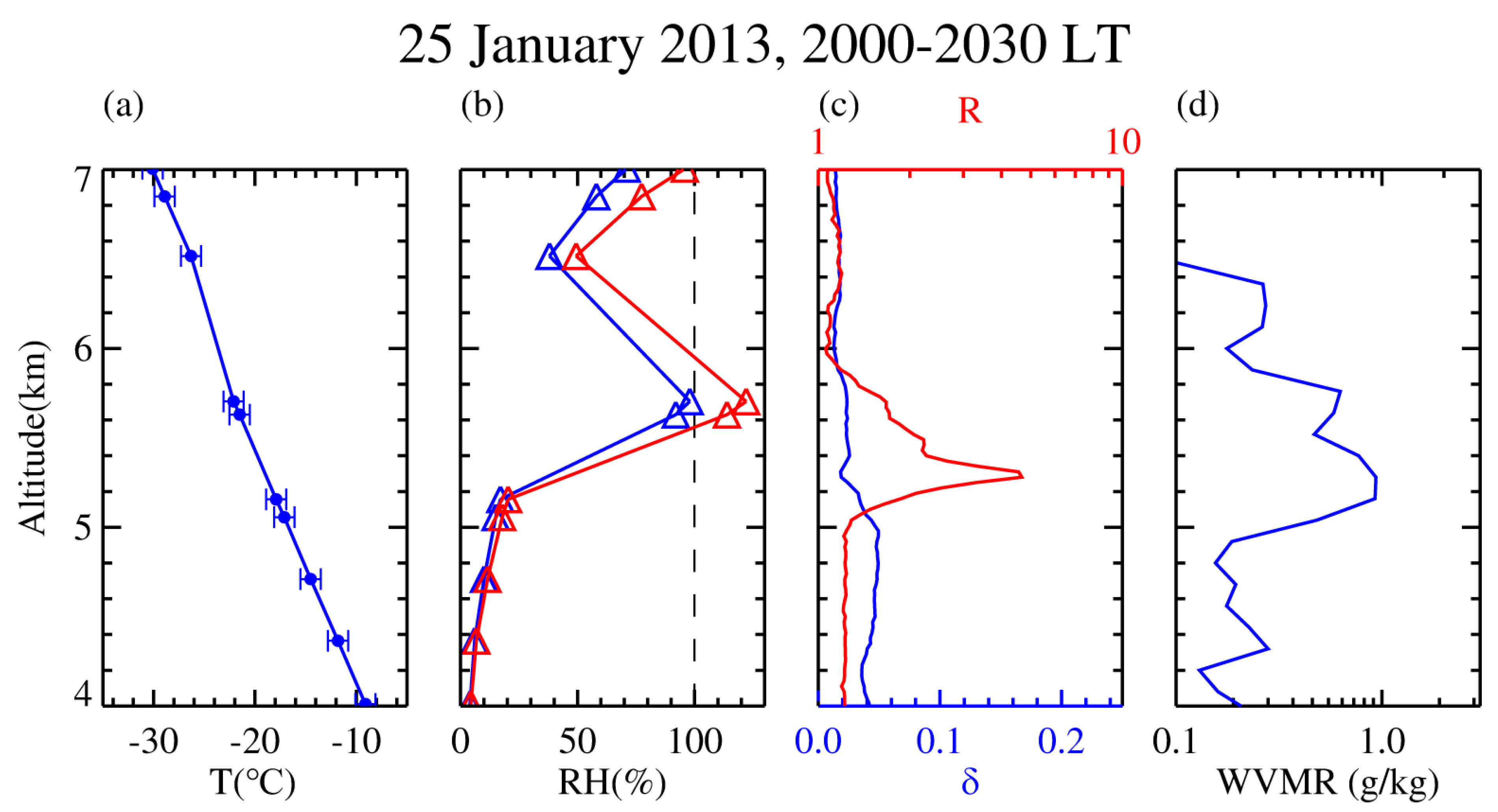
The radiosonde data from Wuhan Weather Station (~23.4 km away from our lidar site) allow us to illustrate the ambient conditions immediately before the liquid-layer-topped ice virga formed. Figure 3 plots the profiles of the temperature T and relative humidity (RH) from a conventional radiosonde around 20:00 LT on 25 January 2013. For the convenience of comparison, the average profiles of the backscatter ratio R, volume depolarization ratio δ and water vapor mixing ratio from our lidar measurements between 2000 and 2030 LT are also given. The R and δ profiles show that the aerosol/liquid water layer resided at altitudes of 5.2–5.8 km (with a peak R value of 4.7 corresponding to a δ minimum value at ~5.3 km altitude). The layer temperature ranged from −17 to −22 °C. This indicates that the liquid-only layer could form and maintain at a low ambient temperature around −17 °C. Despite a supersaturation with respect to ice water being present within the layer (at ~5.7 km altitude), no bulk ice particles were observed (as shown by the low depolarization ratio value).
As shown in Figure 1, the aerosol/liquid water layer strengthened suddenly at its top at 2119 LT, with a peak R value of ~50 and low δ value (δ < 0.05), indicating that a thin liquid-droplet cloud layer began forming on the top of the preexisting aerosol/liquid water layer. A few minutes later, the precipitation streaks occurred at altitudes below the thin liquid-droplet cloud layer. The precipitation streaks exhibited high peak depolarization ratio values (δ ~ 0.2) and slightly large peak backscatter ratio values (R ~ 10). This represents the onset of the liquid-layer-topped ice virga. It is apparent that the thin liquid-droplet cloud layer was the parent cloud of the falling ice virga. The ice virga had an altitude extension of ~300–500 m.
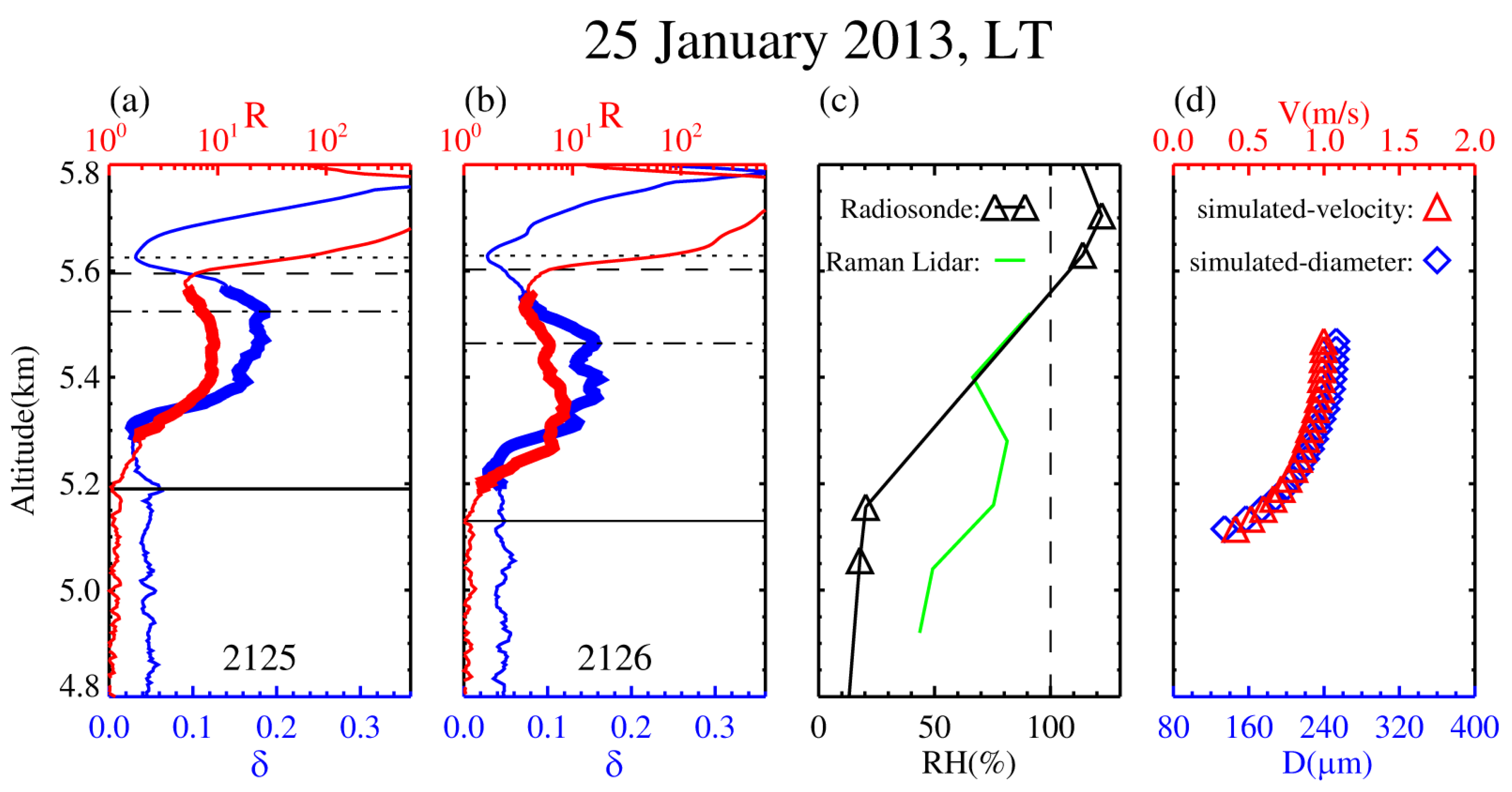
In order to illustrate the ice virga evolution process, two sequential 1-min profiles of the backscatter ratio R and depolarization ratio δ have been plotted in Figure 4 with a high altitude resolution of 3.75 m. As seen in Figure 4, the difference between the δ-minimum height (the liquid-only level) and the height of R = 7.0 changed very little from one 1-min profile to another. Furthermore, each R profile displayed a clear inflection point around the height of R = 7.0 where the slope of the R profile varied significantly. Therefore, the parent cloud base height can be well defined by the height of R = 7.0. The enhanced depolarization ratio layer below the parent cloud base height represent the falling ice virga. The ice virga layer showed similar structures (coherence) and downward shift on the two sequential 1-min δ profiles. A falling speed of bulk ice particles (~0.937 ms-1) can be estimated from the altitude difference of the ice virga layer on the two 1-min δ profiles. The speed value is consistent with the previous observations at similar altitudes [46]. Our observational results suggest that the in-virga ice particles came from the freezing of drizzle-size water drops during their gravitational sedimentation. The drizzle-size water drops formed via turbulence-induced collisions in the high-concentration (large R value) liquid-only layer immediately above the ice virga layer.
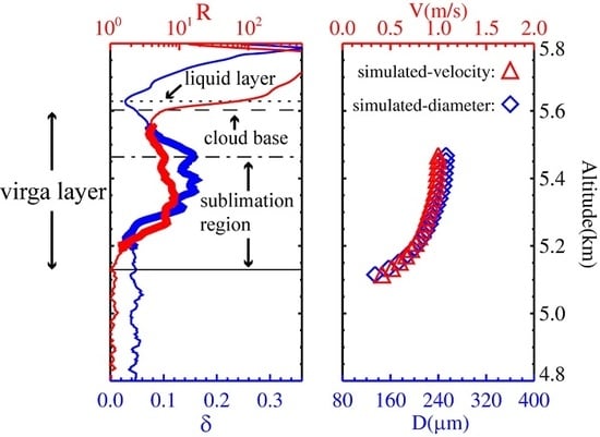
Surveying the R and δ profiles for the liquid-layer-topped ice virga from top to bottom, we can discriminate the three different stages for the ice virga process. The first stage reflects “drizzle-size liquid drop sedimentation” which is characterized by a slight enhancement in the depolarization ratio from the height of the minimum δ value down to that of the parent cloud base (~5.6km). The large liquid drops were settling to the bottom of the liquid parent cloud layer in this stage (corresponding to an altitude range of ~26 m). The second stage represents “freezing of falling liquid drops” which happened primarily in an altitude range of the δ increase from the parent cloud base down to the maximum δ value. During this stage, although most supercooled water droplets were frozen into ice crystals while remaining spherical, the δ value could increase to more than 0.2 [47]. The altitude ranges corresponding to this stage were respectively ~71 and 139 m in terms of the two sequential 1-min profiles (Figure 4a,b). Given a falling speed of ~1 ms-1 for the bulk ice crystals, the second stage had a characteristic time of 71–139 s, which was on the same order as the freezing time of a supercooled water droplet measured in laboratory environment [48]. Noticing a fact that the freezing altitude range was situated within the existing aerosol/liquid water layer, a potential mechanism for the ice crystal formation might be the contact freezing. The third stage presents “ice crystal sublimation” which is characterized by an overall δ decrease from the altitude of the maximum δ value down to that of the background δ value (e.g., ~0.04 at 5.22 km in Figure 4b). Accordingly, the backscatter ratio also dropped to a background value (~1.1) around the 5.13 km height. The “ice crystal sublimation” stage corresponds to an altitude range of ~ 330 m (a characteristic time of ~330 s). In fact, the sublimation should have begun in the second stage where the relative humidity over ice is less than 100%. But the sublimation process therein was concealed by the dominant liquid drop freezing.
In terms of the empirical formula (Equation (3)) on the relationship between the terminal velocity and particle diameter, the pristine ice crystals with the falling speed of ~1 ms-1 (0.937 ms-1) were calculated to have a diameter of ~256 µm assuming that they are near-spherical particles. The altitude variations of ice particle diameter and corresponding terminal velocity were obtained by solving Equations (2) and (3) numerically with an increment of 3.75 m (Figure 4d). The calculation was performed in an altitude range of the δ value reduction (the ice crystal sublimation stage from 5.47 km to 5.13 km) where the relative humidity was interpolated to 3.75-m grid points. The calculated results showed that the ice crystal particles on the bottom of the virga had a diameter of ~129 µm, which is similar to that detected by in situ measurement [49,50]. In addition, the altitude variation of the calculated ice particle diameter is in general similar to the lidar depolarization ratio profile in the same altitude range, suggesting that the decreasing depolarization ratio were resulting from the shrinking ice particles due to sublimation during their descent. The present calculation is actually a forward integration of Equation (2) to solve the ice particle sublimation problem. In order to determine the diameters of the ice crystal particles falling out of the liquid water cloud, a backward integration was applied to solve the ice particle sublimation problem under the assumption that the ice crystal particles on the bottom of the virga had an identical initial diameter for all the lidar profiles. The identical initial diameter was set to the value of ~129 µm from the forward integration. With the initial diameter value of the ice crystal particles, we obtained the diameters (238–632 µm) of the ice crystal particles falling out of the liquid water cloud via the backward integration to Equation (2) for all the lidar ice virga profiles shown in Figure 1.

3.2. Case Study 2 (28–29 March 2016)

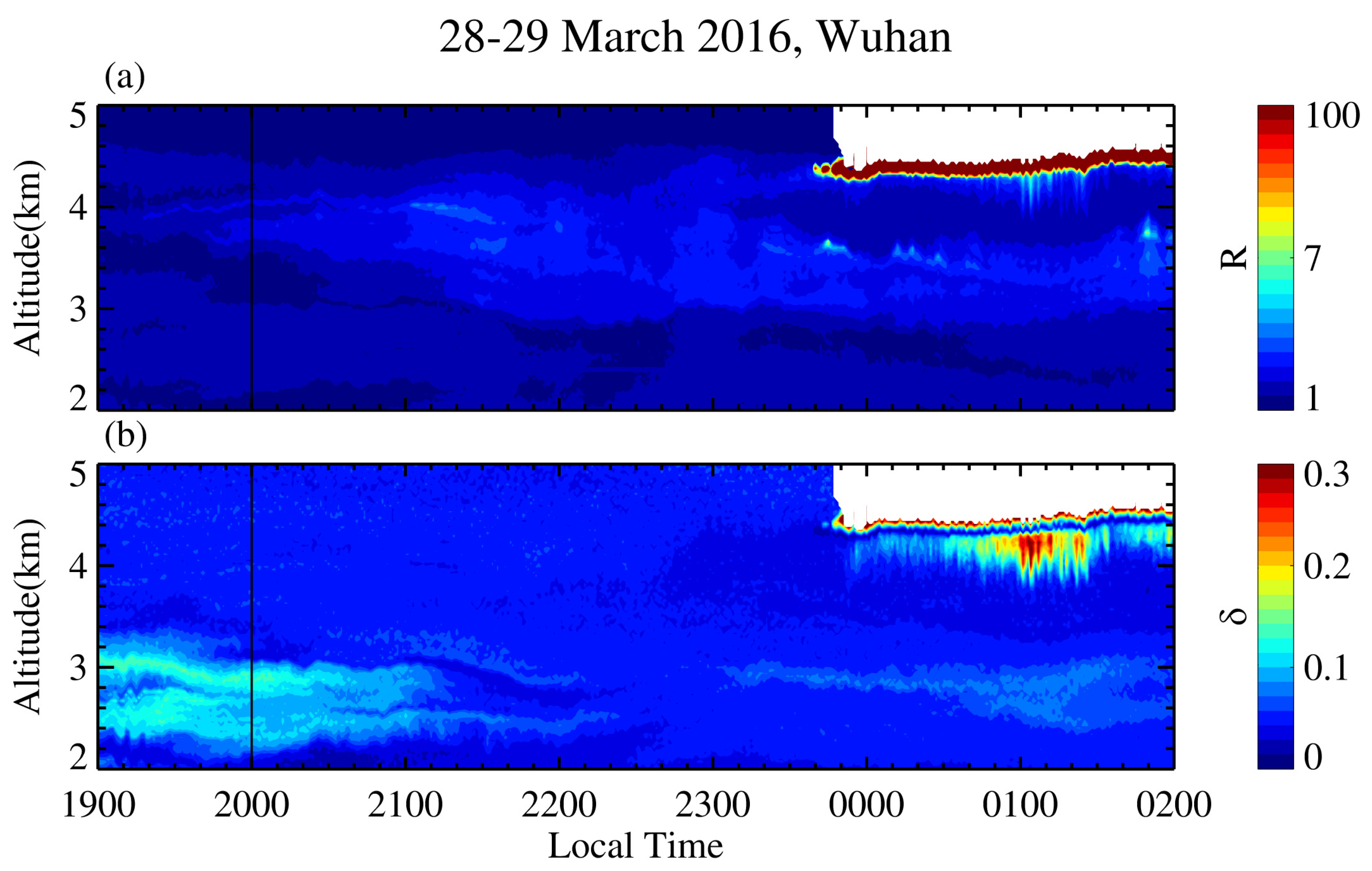
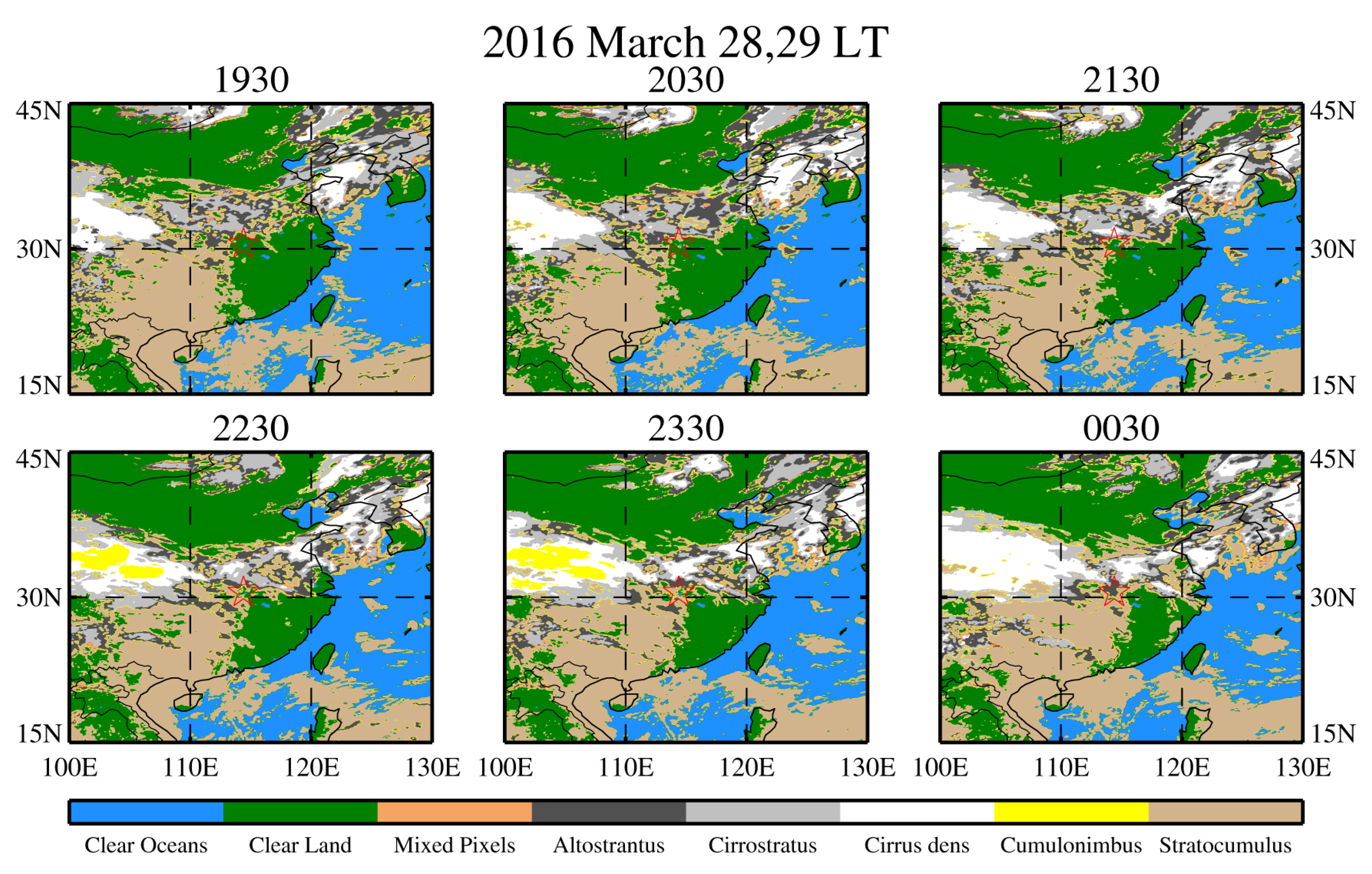
Figure 5 shows another example of the lidar-observed ice virga from 28–29 March 2016. As seen from Figure 5, a thin high-R cloud layer began forming on the top (at ~4.5-km) of a preexisting aerosol/liquid water layer at ~2340 LT. This is consistent with the first example. The ice virga was present below the base height of the cloud layer in a few minutes. The parent cloud layer and its underlying ice virga lasted for over two hours. As shown in Figure 6, the regional clouds-scenario had a greater coverage than case 1. The parent cloud layer had some features similar to the first example. An inflection point around the height of R = 7.0 is clearly discernible for each lidar R profile, which presents the cloud base of the parent cloud layer. The depolarization radio δ reached its minimum value (~0.04) at an altitude of ~29 m above the base height (~29 m into the cloud layer), indicating a liquid-only level therein. In contrast with the slow descent shown in the first example, the parent cloud layer exhibited a slow ascent. The ice virga exhibited burst-like enhancements (the ice virga had larger δ and R values and larger vertical extension) during the period from 0100 to 0130 LT.
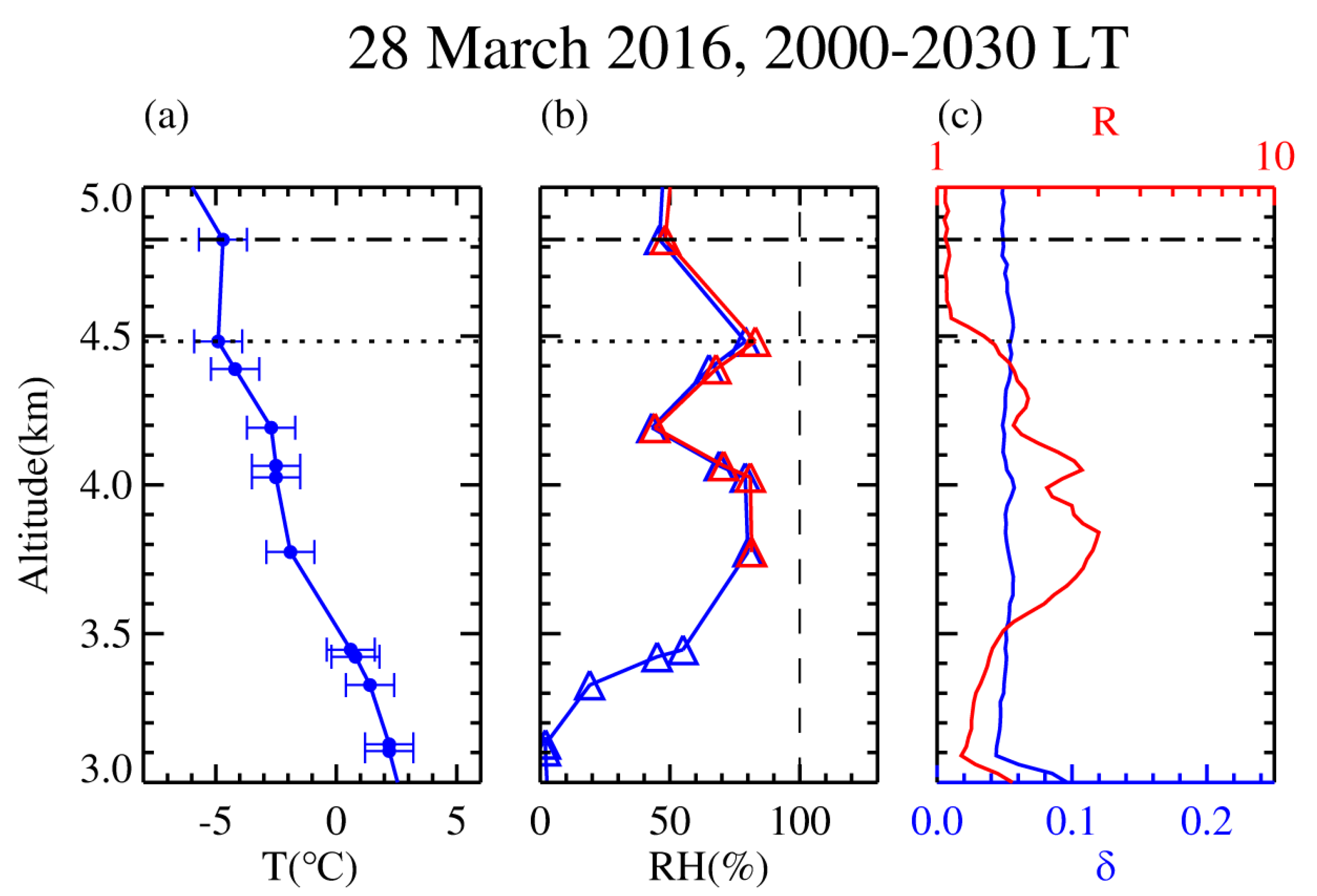
Figure 7 presents the ambient conditions and the mean R and δ profiles about 3 h before the ice virga formed. An inversion layer was discernible at altitudes of 4.5–4.8 km with a temperature minimum of ~ −4.9 °C. An aerosol layer with a maximum R value of ~3.0 occurred at altitudes of 3.5–4.5 km that was just below the inversion layer, which may be caused by the heating of cloud formation during condensation processes [51]. The aerosol layer had a relative humidity of ~80% and depolarization ratio less than 0.05, suggesting that it was an aerosol/liquid water layer. The aerosol/liquid water layer emerging prior to the thin high-R parent cloud layer represented a precursor of the ice virga.
Figure 8a,b presents two sequential 1-min profiles of backscatter ratio and depolarization ratio obtained by the polarization lidar at 0123 and 0124 LT on 29 March 2016. Similar to the first example, we could also identify the three different stages of the ice virga process from the R and δ profiles. In contrast to the first example, the δ-minimum height in the parent cloud dropped by ~30 m during the period of 0123–0124 LT. In addition, the R value of the ice virga declined persistently with decreasing altitude. Noting the similar structures and downward shift shown on the two sequential 1-min δ profiles, a falling speed of bulk ice particles (~1.5 ms-1) was estimated from the altitude difference of the ice virga layer on the two 1-min δ profiles. According to Equation (3), the pristine ice crystals with the falling speed of ~1.5 ms-1 had a diameter of ~344 µm assuming that they are near-spherical particles. The altitude variations of ice particle radius and corresponding terminal velocity were calculated based on a forward integration to the ice particle sublimation Equation (2). The results are given in Figure 8d. In the calculation, the relative humidity profile around 2000 LT on 28 March 2016 (Figure 8c) was employed and an initial diameter was set to ~344 µm at the altitude of ~4.23 km. The final diameter of the ice crystal particles on the bottom (~3.84 km) of the virga was ~110 µm. This value is close to the result (~129 µm) in the first example. Note that the R and δ values were respectively ~1.1 and ~0.04 at the altitude of ~3.84 km. Assuming that the final diameters of the ice crystal particles on the ice virga bottom were identical (~110 µm), we obtained the diameter values (242-444 µm) of the ice crystal particles at the altitudes of the maximum δ value via the backward integration to Equation (2) for all the lidar ice virga profiles shown in Figure 5.

4. Overall Statistics and Discussion

The above two observation examples have revealed some common features of the falling mixed-phase virga from supercooled liquid layer cloud base. The similar features have been discerned also on the other eighteen cases from our lidar observations between January 2011 and December 2017. Table 1 provides an overview of the liquid-layer-topped ice virga properties in all cases. Seven of these cases had an inversion layer above the ice virga similar to case 2. The maximum RH usually appeared at the top of ice virga similar to case 1. For each liquid-layer-topped ice virga observed by our lidar, the associated R and δ profiles could be divided into the three different altitude segments from top to bottom. The first is characterized by a slight enhancement in the depolarization ratio from the height of the minimum δ value down to that of the parent cloud base (the R inflection point and R = 7.0). This segment had an average thickness of ~34 m and a mean δ value ranging from 0.04 (top) to 0.07 (bottom). It might reflect that the large liquid drops were settling at the bottom of the liquid parent cloud layer. The second corresponds to the altitude range of the δ increase from the parent cloud base down to the maximum δ value. Its average thickness was ~236 m. This value is similar to the radar-observed result that mostly pristine ice crystals formed in mixed-phase layers within 350 m below the parent cloud [11]. In this segment, the enhanced δ value with decreasing altitude should primarily represent the freezing of falling liquid drops. By using the same method used above, the bulk ice particles for the total of 20 observational virga cases were estimated to have an average falling speed of ~1.45 ms-1. It is a preliminary statistical result, and the lack of vertical wind field data prevented further analysis. Given the average thickness of ~236 m for the second segment, we obtained a time scale of ~160 s for the freezing of falling liquid drops. The time scale is larger than the typical value for a single droplet freezing in constant temperature around −25 °C [21,52]. The third is characterized by an overall δ decrease from the altitude of the maximum δ value down to that of the background δ value. Furthermore, the backscatter ratio R also reached a background value at the bottom in this segment. In this segment, the declined δ value with decreasing altitude depicts the ice crystal sublimation. For each case, we estimated the altitude variations of the ice crystals diameters by the sublimation model used above, and the mean diameter of the ice crystal particles on the ice virga bottom is ~112 µm.
The R profiles of the falling mixed-phase virga have two types. One is the distorted Gaussian shape as shown in Figure 4a,b. This type occupied ~91% of the entire ice virga profiles in present study. Another is the steady attenuation curve with decreasing altitude like that shown in Figure 7a,b, which accounted for ~9%. The high percentage of the distorted Gaussian-shape profiles might suggest that the bulk hydrometeors falling from the liquid parent cloud were mostly discontinuous.
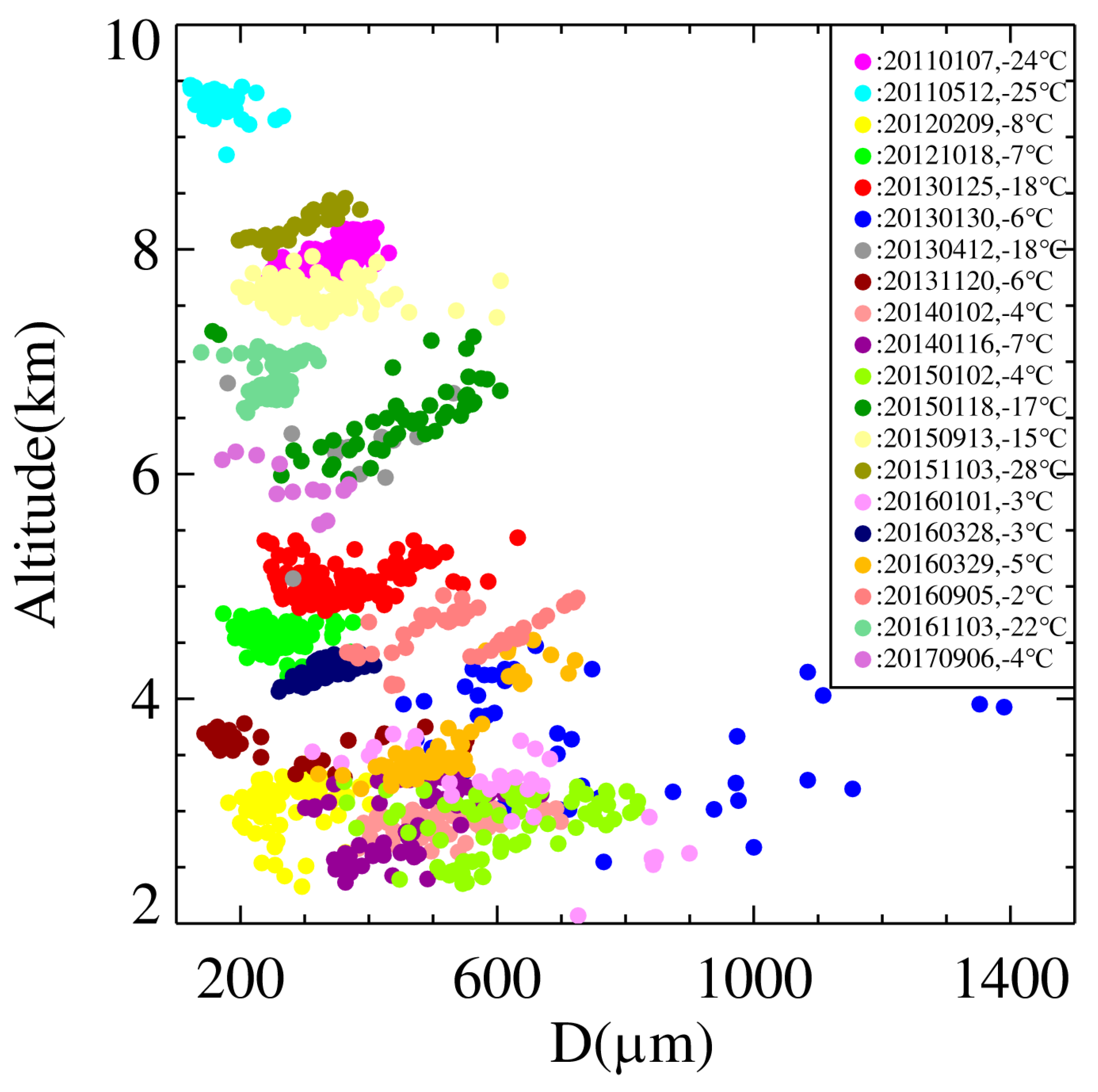
In order to obtain the statistically-significant results on the diameters of the ice crystal particles falling out of the liquid water cloud (at the altitudes of the maximum δ value), we have numerically solved Equation (2) for the remaining 18 virga cases by assuming the final diameters of the ice crystal particles on the ice virga bottom were identical (~112 µm). Figure 9 presents a plot of the calculated diameters versus altitude for all the 20 ice virga events observed by our lidar. Based on the quasi-simultaneous radiosonde data, the ambient temperatures of these ice virga range from −3 °C to −25 °C at altitudes of 2.3–9.4 km, indicating that the ice crystals formed via heterogeneous nucleation. The in-virga ice crystal particles have the diameters varying between 122 and 1390 µm, that are similar to the effective mean diameters of ice crystals at the same temperature levels [53,54]. The estimation of ice particles size is based on the relationship between diameter and the velocity of the spherical ice crystal and could be optimized by the accurate shape of the ice crystal detected by in situ measurements. A primary feature of Figure 9 is that the ice crystal particles in these virga cases tend to have smaller diameters and narrower size distributions with increasing altitude. There was only one virga case present at altitudes above 8.5 km. It had the mean diameters around 200 µm. This size (200 µm) was smallest of the 20 observed virga cases. Out of the total 20 virga cases, 11 occurred in an altitude range of 4–8.5 km. The ice crystal particles for the 11 cases had a mean diameter of 350 ± 111 µm. For the virga present at altitudes of 2–4 km, the ice crystal particles had much broader size distributions than those at higher altitudes. The large water vapor concentration and slightly-high temperature in this altitude range might be responsible for the broader size distribution [55].

5. Conclusions

The evolution of the falling mixed-phase ice virga from their liquid parent cloud base has been observed by ground-based lidars at Wuhan (30.5 °N, 114.4 °E), China. The clear liquid-layer-topped ice virga were identified on 20 occasions from our lidar measurements from January 2011 to December 2017. They were present at altitudes of 2.3–9.4 and lasted for more than 2 h. All the cases started with clear-sky conditions until obvious precipitation appeared. The thin liquid water cloud layer formation as indicated by high backscatter ratio R and low depolarization δ occurred on the top of a preexisting aerosol/liquid water layer, and the mixed-phase ice virga formation as indicated by high δ occurred continuously below the base height of the cloud layer.
For illustrating the ice virga evolution process, two observations with steady meteorological conditions were presented in detail as examples. They exhibited some common features of the liquid-layer-topped ice that are similar in the remaining 18 cases. According to the characteristics of the associated R and δ profiles observed by our lidar, each falling mixed-phase virga with their liquid parent cloud layer could be divided into the three different altitude segments from top to bottom. The first segment (an average thickness of ~34 m) is characterized by a slight enhancement in the depolarization ratio from the height of minimum δ value (~0.04) down to that of the parent cloud base. Herein the cloud base is well-defined by the height of R = 7.0 where is generally the inflection point of the backscatter ratio R profile. In this segment, a liquid-only level existed on the top and the large liquid drops sedimentation was formed around the parent cloud layer base. The second corresponds to the altitude range of the depolarization ratio δ increase significantly from the parent cloud base down to the maximum δ value. It is suggested that most falling liquid drops down from cloud were rapidly frozen into ice crystals in the virga situated within the existing aerosol/liquid water layer, and the potential mechanism for ice crystal formation might be the contact freezing. This segment has an average thickness of ~236 m. The third segment is characterized by an overall δ decrease from the altitude of the maximum δ value down to the background δ value where the backscatter ratio R also reach a background value simultaneously. In this segment, the ice virga gradually weakened in intensity and no bulk ice particles were detected on the bottom. The main physical processes in these three altitude segments from top to bottom are corresponding to the three stages of the water droplets phase transition: drizzle-size liquid drop sedimentation, freezing of falling liquid drops and ice crystal sublimation.
Based on the two sequential 1-min temporal resolution and 3.75 m vertical resolution profiles of the backscatter ratio R and depolarization ratio δ during the strong virga, the falling speed of bulk ice particles can be estimated from the downward shift of similar structures (coherence) on ice virga layer. Furthermore, we calculated the altitude variations of the ice crystals diameters in the virga by the relationship between the terminal velocity and particle diameter and ice particle sublimation model along with the lidar and radiosonde observations. In terms of a statistics from all the 20 ice virga events, the ice virga occurred at ambient temperatures from −3 °C to −25 °C which is similar to the result from the earlier observations [56]. The in-virga ice crystal particles have the diameters varying between 122 and 1390 µm and tend to have smaller diameters and narrower size distributions with increasing altitude. More than half of the cases occurred in an altitude range of 4–8.5 km, and the mean diameter value is 350 ± 111 µm therein.

Author Contributions

Conceptualization, C.C. and F.Y.; methodology, C.C. and F.Y.; data curation, C.C.; writing—original draft preparation, C.C.; writing—review and editing, F.Y.; funding acquisition, F.Y. All authors have read and agreed to the published version of the manuscript.”

Funding

This research is funded by the National Natural Science Foundation of China through grants 41927804. The Meridian Space Weather Monitoring Project (China) also provides financial support for the lidar maintenance.

Acknowledgments

The authors extend particular thanks to the University of Wyoming for providing the Wuhan radiosonde data at the website (http://weather.uwyo.edu/upperair/sounding.html) and thanks to the National Satellite Meteorological Center for providing the satellite images at the website (http://data.cma.cn/data/detail/dataCode/SK.0261.001.html). Data used to generate the results of this paper are available from the authors upon request (E-mail:[email protected]).

Conflicts of Interest

The authors declare that we have no financial and personal relationships with other people or organizations that can inappropriately influence our work and that this paper was not published before, the funding sponsors had no role in the design of the study; in the collection, analyses, or interpretation of data; in the writing of the manuscript, and in the decision to publish the results.

References

  1. Thompson, G.; Field, P.R.; Rasmussen, R.M.; Hall, W.D. Explicit Forecasts of Winter Precipitation Using an Improved Bulk Microphysics Scheme. Part II: Implementation of a New Snow Parameterization. Mon. Weather. Rev. 2008, 136, 5095–5115. [Google Scholar] [CrossRef]
  2. Muelmenstaedt, J.; Sourdeval, O.; Delanoe, J.; Quaas, J. Frequency of occurrence of rain from liquid-, mixed-, and ice-phase clouds derived from A-Train satellite retrievals. Geophys. Res. Lett. 2015, 42, 6502–6509. [Google Scholar] [CrossRef] [Green Version]
  3. Matus, A.V.; L’Ecuyer, T.S. The role of cloud phase in Earth’s radiation budget. J. Geophys. Res. Atmos. 2017, 122, 2559–2578. [Google Scholar] [CrossRef]
  4. Stephens, G.L.; Li, J.; Wild, M.; Clayson, C.A.; Loeb, N.; Kato, S.; L’Ecuyer, T.; Stackhouse, P.W., Jr.; Lebsock, M.; Andrews, T. An update on Earth’s energy balance in light of the latest global observations. Nat. Geosci. 2012, 5, 691–696. [Google Scholar] [CrossRef]
  5. Zhang, D.; Wang, Z.; Liu, D. A global view of midlevel liquid-layer topped stratiform cloud distribution and phase partition from CALIPSO and CloudSat measurements. J. Geophys. Res. Atmos. 2010, 115. [Google Scholar] [CrossRef] [Green Version]
  6. Morrison, H.; de Boer, G.; Feingold, G.; Harrington, J.; Shupe, M.D.; Sulia, K. Resilience of persistent Arctic mixed-phase clouds. Nat. Geosci. 2012, 5, 11–17. [Google Scholar] [CrossRef]
  7. Buhl, J.; Seifert, P.; Engelmann, R.; Ansmann, A. Impact of vertical air motions on ice formation rate in mixed-phase cloud layers. NPJ Clim. Atmos. Sci. 2019, 2, 36. [Google Scholar] [CrossRef]
  8. Ansmann, A.; Tesche, M.; Seifert, P.; Althausen, D.; Engelmann, R.; Fruntke, J.; Wandinger, U.; Mattis, I.; Muller, D. Evolution of the ice phase in tropical altocumulus: SAMUM lidar observations over Cape Verde. J. Geophys. Res. Atmos. 2009, 114, D17. [Google Scholar] [CrossRef] [Green Version]
  9. De Boer, G.; Eloranta, E.W.; Shupe, M.D. Arctic Mixed-Phase Stratiform Cloud Properties from Multiple Years of Surface-Based Measurements at Two High-Latitude Locations. J. Atmos. Sci. 2009, 66, 2874–2887. [Google Scholar] [CrossRef] [Green Version]
  10. Westbrook, C.D.; Illingworth, A.J. Evidence that ice forms primarily in supercooled liquid clouds at temperatures >−27 °C. Geophys. Res. Lett. 2011, 38. [Google Scholar] [CrossRef]
  11. Bühl, J.; Seifert, P.; Myagkov, A.; Ansmann, A. Measuring ice- and liquid-water properties in mixed-phase cloud layers at the Leipzig Cloudnet station. Atmos. Chem. Phys. 2016, 16, 10609–10620. [Google Scholar] [CrossRef] [Green Version]
  12. Buhl, J.; Seifert, P.; Radenz, M.; Baars, H.; Ansmann, A. Ice crystal number concentration from lidar, cloud radar and radar wind profiler measurements. Atmos. Meas. Tech. 2019, 12, 6601–6617. [Google Scholar] [CrossRef] [Green Version]
  13. Ansmann, A.; Tesche, M.; Althausen, D.; Mueller, D.; Seifert, P.; Freudenthaler, V.; Heese, B.; Wiegner, M.; Pisani, G.; Knippertz, P.; et al. Influence of Saharan dust on cloud glaciation in southern Morocco during the Saharan Mineral Dust Experiment. J. Geophys. Res. Atmos. 2008, 113, D4. [Google Scholar] [CrossRef]
  14. De Boer, G.; Morrison, H.; Shupe, M.D.; Hildner, R. Evidence of liquid dependent ice nucleation in high-latitude stratiform clouds from surface remote sensors. Geophys. Res. Lett. 2011, 38. [Google Scholar] [CrossRef] [Green Version]
  15. Ansmann, A.; Mattis, I.; Muller, D.; Wandinger, U.; Radlach, M.; Althausen, D.; Damoah, R. Ice formation in Saharan dust over central Europe observed with temperature/humidity/aerosol Raman lidar. J. Geophys. Res. Atmos. 2005, 110, D18. [Google Scholar] [CrossRef]
  16. Rosenfeld, D.; Woodley, W.L. Deep convective clouds with sustained supercooled liquid water down to −37.5  °C. Nature 2000, 405, 440–442. [Google Scholar] [CrossRef] [PubMed]
  17. Sassen, K.; Khvorostyanov, V.I. Microphysical and radiative properties of mixed-phase altocumulus: A model evaluation of glaciation effects. Atmos. Res. 2007, 84, 390–398. [Google Scholar] [CrossRef]
  18. Nevzorov, A.N. Internal mechanism of metastable liquid water crystallization and its effects on intracloud processes. Izv. Atmos. Ocean. Phys. 2006, 42, 765–772. [Google Scholar] [CrossRef]
  19. Murray, B.J.; O’Sullivan, D.; Atkinson, J.D.; Webb, M.E. Ice nucleation by particles immersed in supercooled cloud droplets. Chem. Soc. Rev. 2012, 41, 6519–6554. [Google Scholar] [CrossRef] [Green Version]
  20. Phillips, V.T.J.; Patade, S.; Gutierrez, J.; Bansemer, A. Secondary Ice Production by Fragmentation of Freezing Drops: Formulation and Theory. J. Atmos. Sci. 2018, 75, 3031–3070. [Google Scholar] [CrossRef]
  21. Hindmarsh, J.P.; Russell, A.B.; Chen, X.D. Experimental and numerical analysis of the temperature transition of a suspended freezing water droplet. Int. J. Heat Mass Transf. 2003, 46, 1199–1213. [Google Scholar] [CrossRef]
  22. Pruppacher, H.R.; Klett, J.D. Microphysics of Clouds and Precipitation; Kluwer Academic Publishers: Dordrecht, The Netherlands, 1997. [Google Scholar]
  23. Korolev, A.V.; Bailey, M.P.; Hallett, J.; Isaac, G.A. Laboratory and in situ observation of deposition growth of frozen drops. J. Appl. Meteorol. 2004, 43, 612–622. [Google Scholar] [CrossRef]
  24. Zobrist, B.; Koop, T.; Luo, B.P.; Marcolli, C.; Peter, T. Heterogeneous ice nucleation rate coefficient of water droplets coated by a nonadecanol monolayer. J. Phys. Chem. C 2007, 111, 2149–2155. [Google Scholar] [CrossRef]
  25. Yang, J.; Wang, Z.E.; Heymsfield, A. On the freezing time of supercooled drops in developing convective clouds over tropical ocean. Atmos. Res. 2018, 211, 30–37. [Google Scholar] [CrossRef]
  26. Khain, A.P.; Beheng, K.D.; Heymsfield, A.; Korolev, A.; Krichak, S.O.; Levin, Z.; Pinsky, M.; Phillips, V.; Prabhakaran, T.; Teller, A.; et al. Representation of microphysical processes in cloud-resolving models: Spectral (bin) microphysics versus bulk parameterization. Rev. Geophys. 2015, 53, 247–322. [Google Scholar] [CrossRef]
  27. Kong, W.; Yi, F. Convective boundary layer evolution from lidar backscatter and its relationship with surface aerosol concentration at a location of a central China megacity. J. Geophys. Res. Atmos. 2015, 120, 7928–7940. [Google Scholar] [CrossRef]
  28. Freudenthaler, V.; Esselborn, M.; Wiegner, M.; Heese, B.; Tesche, M.; Ansmann, A.; MüLler, D.; Althausen, D.; Wirth, M.; Fix, A.; et al. Depolarization ratio profiling at several wavelengths in pure Saharan dust during SAMUM 2006. Tellus B Chem. Phys. Meteorol. 2009, 61, 165–179. [Google Scholar] [CrossRef] [Green Version]
  29. Shupe, M.D. A ground-based multisensor cloud phase classifier. Geophys. Res. Lett. 2007, 34, 5. [Google Scholar] [CrossRef] [Green Version]
  30. Intrieri, J.M.; Shupe, M.D.; Uttal, T.; McCarty, B.J. An annual cycle of Arctic cloud characteristics observed by radar and lidar at SHEBA. J. Geophys. Res. Oceans 2002, 107, C10. [Google Scholar] [CrossRef]
  31. Shupe, M.D.; Daniel, J.S.; de Boer, G.; Eloranta, E.W.; Kollias, P.; Long, C.N.; Luke, E.P.; Turner, D.D.; Verlinde, J. A Focus ON Mixed-Phase Clouds The Status of Ground-Based Observational Methods. B Am. Meteorol. Soc. 2008, 89, 1549. [Google Scholar] [CrossRef] [Green Version]
  32. Fernald, F.G. Analysis of atmospheric lidar observations: Some comments. Appl. Optics 1984, 23, 652–653. [Google Scholar] [CrossRef] [PubMed]
  33. O’Connor, E.J.; Illingworth, A.J.; Hogan, R.J. A technique for autocalibration of cloud lidar. J. Atmos. Ocean. Tech. 2004, 21, 777–786. [Google Scholar] [CrossRef]
  34. Wang, Z.; Sassen, K. Cloud type and macrophysical property retrieval using multiple remote sensors. J. Appl. Meteorol. 2001, 40, 1665–1682. [Google Scholar] [CrossRef]
  35. Morille, Y.; Haeffelin, M.; Drobinski, P.; Pelon, J. STRAT: An automated algorithm to retrieve the vertical structure of the atmosphere from single-channel lidar data. J. Atmos. Ocean. Tech. 2007, 24, 761–775. [Google Scholar] [CrossRef] [Green Version]
  36. Wu, C.; Yi, F. Local ice formation via liquid water growth in slowly ascending humid aerosol/liquid water layers observed with ground-based lidars and radiosondes. J. Geophys. Res. Atmos. 2017, 122, 4479–4493. [Google Scholar] [CrossRef]
  37. Whiteman, D.N.; Melfi, S.H.; Ferrare, R.A. Raman lidar system for the measurement of water vapor and aerosols in the Earth’s atmosphere. Appl. Opt. 1992, 31, 3068–3082. [Google Scholar] [CrossRef]
  38. Nash, J.; Oakley, T.; Vömel, H.; Li, W. WMO Intercomparison of High Quality Radiosonde Systems; WMO Tech.Doc.WMO/TD-1580; WMO: Geneva, Switzerland, 2011; p. 238. [Google Scholar]
  39. Huang, Y.; Meng, Z.; Li, J.; Li, W.; Bai, L.; Zhang, M.; Wang, X. Distribution and Variability of Satellite-Derived Signals of Isolated Convection Initiation Events Over Central Eastern China. J. Geophys. Res. Atmos 2017, 122, 11357–11373. [Google Scholar] [CrossRef]
  40. Jost, A.; Szakáll, M.; Diehl, K.; Mitra, S.K.; Hundertmark, A.; Klug, B.S.; Borrmann, S. The Effect of Turbulence on the Accretional Growth of Graupel. J. Atmos. Sci. 2019, 76, 3047–3061. [Google Scholar] [CrossRef]
  41. Seifert, A.; Beheng, K.D. A two-moment cloud microphysics parameterization for mixed-phase clouds. Part 1: Model description. Meteorol. Atmos. Phys. 2006, 92, 45–66. [Google Scholar] [CrossRef]
  42. Cotton, W.R.; Tripoli, G.J.; Rauber, R.M.; Mulvihill, E.A. Numerical Simulation of the Effects of Varying Ice Crystal Nucleation Rates and Aggregation Processes on Orographic Snowfall. J. Clim. Appl. Meteorol. 1986, 25, 1658–1680. [Google Scholar] [CrossRef] [Green Version]
  43. Harrington, J.Y.; Meyers, M.P.; Walko, R.L.; Cotton, W.R. Parameterization of Ice Crystal Conversion Processes Due to Vapor Deposition for Mesoscale Models Using Double-Moment Basis Functions. Part I: Basic Formulation and Parcel Model Results. J. Atmos. Sci. 1995, 52, 4344–4366. [Google Scholar] [CrossRef] [Green Version]
  44. Heymsfield, A.J.; Westbrook, C.D. Advances in the Estimation of Ice Particle Fall Speeds Using Laboratory and Field Measurements. J. Atmos. Sci. 2010, 67, 2469–2482. [Google Scholar] [CrossRef] [Green Version]
  45. Böhm, H.P. A General Equation for the Terminal Fall Speed of Solid Hydrometeors. J. Atmos. Sci. 1989, 46, 2419–2427. [Google Scholar] [CrossRef]
  46. Barrett, A.I.; Westbrook, C.D.; Nicol, J.C.; Stein, T.H.M. Rapid ice aggregation process revealed through triple-wavelength Doppler spectrum radar analysis. Atmos. Chem. Phys. 2019, 19, 5753–5769. [Google Scholar] [CrossRef] [Green Version]
  47. Roth, N.; Frohn, A. Size and polarization behaviour of optically levitated frozen water droplets. Atmos. Environ. 1998, 32, 3139–3143. [Google Scholar] [CrossRef]
  48. Johnson, D.A.; Hallett, J. Freezing and shattering of supercooled water drops. Q. J. R. Meteorol. Soc. 1968, 94, 468–482. [Google Scholar] [CrossRef]
  49. Crosier, J.; Bower, K.N.; Choularton, T.W.; Westbrook, C.D.; Connolly, P.J.; Cui, Z.Q.; Crawford, I.P.; Capes, G.L.; Coe, H.; Dorsey, J.R.; et al. Observations of ice multiplication in a weakly convective cell embedded in supercooled mid-level stratus. Atmos. Chem. Phys. 2011, 11, 257–273. [Google Scholar] [CrossRef] [Green Version]
  50. Mioche, G.; Jourdan, O.; Delanoe, J.; Gourbeyre, C.; Febvre, G.; Dupuy, R.; Monier, M.; Szczap, F.; Schwarzenboeck, A.; Gayet, J.F. Vertical distribution of microphysical properties of Arctic springtime low-level mixed-phase clouds over the Greenland and Norwegian seas. Atmos. Chem. Phys. 2017, 17, 12845–12869. [Google Scholar] [CrossRef] [Green Version]
  51. Dennis, A.S. Weather Modification by Cloud Seeding; Academic Press: Cambridge, MA, USA, 1980; Volume 24. [Google Scholar]
  52. Bauerecker, S.; Ulbig, P.; Buch, V.; Vrbka, L.; Jungwirth, P. Monitoring Ice Nucleation in Pure and Salty Water via High-Speed Imaging and Computer Simulations. J. Phys. Chem. C 2008, 112, 7631–7636. [Google Scholar] [CrossRef]
  53. Das, S.K.; Nee, J.B.; Chiang, C.W. A LiDAR study of the effective size of cirrus ice crystals over Chung-Li, Taiwan. J. Atmos. Sol. Terr. Phys. 2010, 72, 781–788. [Google Scholar]
  54. Westbrook, C.D.; Illingworth, A.J. The formation of ice in a long-lived supercooled layer cloud. Q. J. Roy. Meteor. Soc. 2013, 139, 2209–2221. [Google Scholar] [CrossRef] [Green Version]
  55. Leroy, D.; Fontaine, E.; Schwarzenboeck, A.; Strapp, J.W.; Korolev, A.; McFarquhar, G.; Dupuy, R.; Gourbeyre, C.; Lilie, L.; Protat, A.; et al. Ice Crystal Sizes in High Ice Water Content Clouds. Part II: Statistics of Mass Diameter Percentiles in Tropical Convection Observed during the HAIC/HIWC Project. J. Atmos. Oceanic. Technol. 2017, 34, 117–136. [Google Scholar]
  56. Myagkov, A.; Seifert, P.; Wandinger, U.; Buhl, J.; Engelmann, R. Relationship between temperature and apparent shape of pristine ice crystals derived from polarimetric cloud radar observations during the ACCEPT campaign. Atmos. Meas. Tech. 2016, 9, 3739–3754. [Google Scholar] [CrossRef] [Green Version]
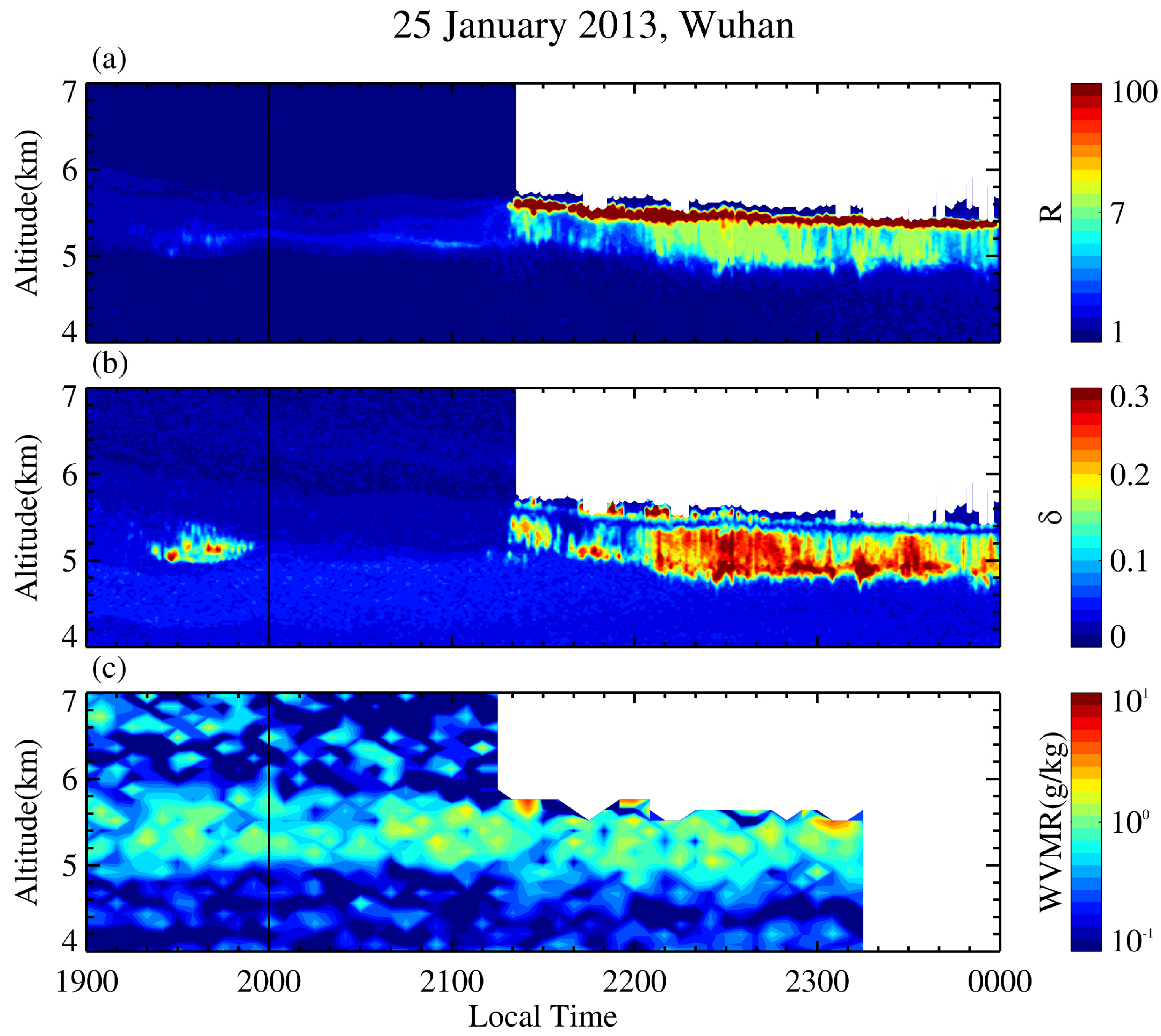
Figure 1. Time-height contour plots of backscatter ratio R (a), volume depolarization ratio δ (b) measured by our 532-nm polarization lidar (1-min/30-m resolution), and the water vapor mixing ratio water vapor mixing ratio (WVMR) (c) measured by Raman Lidar (5-min/120-m resolution) on 25 January 2013. The vertical line at 20:00 LT show the launch time of radiosonde from Wuhan Weather Station. Note that a liquid-layer-topped ice virga is visible from 21:20 to 23:59 LT.
Remotesensing 12 02094 g001
Figure 2. Hourly cloud classification satellite image from the FY-2E geostationary meteorological satellite from 1800 LT to 2300 LT on 25 January 2013. The red star denotes the location of Wuhan. Note that the development of stratocumulus is from dispersion to concentration around Wuhan.
Remotesensing 12 02094 g002
Figure 3. Profiles of (a) temperature T, (b) relative humidity (RH) over liquid water (blue) and over ice (red), measured by radiosonde launched around 2000 LT on 25 January 2013, (c) backscatter ratio (red) and depolarization ratio (blue) obtained by the polarization lidar, and (d) water vapor mixing ratio obtained by the Raman lidar during 2000–2030 LT. The WVMR is not shown at altitudes above 6.5 km because of a low signal-to-noise ratio (SNR).
Remotesensing 12 02094 g003
Figure 4. Two sequential 1-min profiles of backscatter ratio (red) and depolarization ratio (blue) obtained by the polarization lidar at (a) 2125 and (b) 2126 LT on 25 January 2013, (c) Profiles of relative humidity over ice from local radiosonde (black with triangle) at 2000 LT and our Raman lidar (green) around 2125 LT, and (d) altitude variations of ice particle diameter (blue diamond) and corresponding terminal velocity (red triangle) calculated with a conventional ice particle sublimation model mentioned in Section 2.3. The parent cloud base height (R ~ 7.0) and δ -minimum height are indicated by dash and dotted lines, respectively. The depolarization ratio had values larger than 0.15 at altitudes of 5.3–5.5 km, showing the presence of ice crystals. Note that the ice virga layer (~5.25–5.55 km) showed coherent structure (bold line) and altitude shift as seen from the two sequential 1-min δ profiles. This allowed us to estimate the falling speed of bulk ice crystals.
Remotesensing 12 02094 g004
Figure 5. Time-height contour plots of backscatter ratio R (a), volume depolarization ratio δ (b) measured by our 532-nm polarization lidar (1-min/30-m resolution) from 1900 LT on 28 March to 0200 LT on 29 March 2016. The water vapor mixing ratio was not available because the Raman Lidar was on maintenance.
Remotesensing 12 02094 g005
Figure 6. Hourly cloud classification satellite image from the FY-2E geostationary meteorological satellite from 1930 LT on 28 March to 0030 LT on 29 March 2016. The red star denotes the location of Wuhan. Note that stratocumulus covers most of central and western China and spread through Wuhan after 2230 LT.
Remotesensing 12 02094 g006
Figure 7. Profiles of (a) temperature T, (b) relative humidity over liquid water RH (blue) and over ice (red), measured by radiosonde launched around 2000 LT on 28 March 2016, (c) backscatter ratio (red) and depolarization ratio (blue) obtained by the polarization lidar during 2000–2030 LT on the same day. An inversion layer was marked by dotted line.
Remotesensing 12 02094 g007
Figure 8. Two sequential 1-min profiles of backscatter ratio (red) and depolarization ratio (blue) obtained by the polarization lidar at (a) 0123 and (b) 0124 LT on 29 March 2016, (c) Profile of relative humidity over ice from local radiosonde (black with triangle) around 2000 LT on 28 March 2016, and (d) altitude variations of ice particle radius (blue diamond) and corresponding terminal velocity (red triangle) calculated with a conventional ice particle sublimation model mentioned in Section 2.3. The parent cloud base height (R ~ 7.0) and δ -minimum height are indicated by dash and dotted lines, respectively. The depolarization ratio had values larger than 0.2 at altitudes of 4.1–4.3 km, showing the presence of ice crystals. Note that the ice virga layer (~3.9–4.35 km) showed coherent structure and altitude shift as seen from the two sequential 1-min δ profiles. This allowed us to estimate the falling speed of bulk ice crystals.
Remotesensing 12 02094 g008
Figure 9. Altitude dependence of the diameters of the ice crystal particles for all the 20 ice virga events observed by our lidar. Each color stands for one event and each circle denotes a diameter over the 1-min profiles. The mean corresponding temperatures of events are also marked in the legend. Only profiles of the strong ice virga (maximum δ > 0.15) were involved in the calculations and statistics. The diameters were obtained by numerically solving the ice particle sublimation equation under the assumption that the final diameters of the ice crystal particles on the ice virga bottom were identical (observation-based value). Note that the ice crystal particles in these virga cases tend to have smaller diameters and narrower size distributions with increasing altitude.
Remotesensing 12 02094 g009
Table 1. Case data obtained by our lidar and radiosonde are listed below. Thickness is the height difference between liquid layer top and cloud base. Cloud base height and thickness represent the mean values of each case. The inversion layer all occurs at the height of the liquid cloud layer and Max RH refers to the maximum RH over ice within the ice virga layer. The last three terms are estimated by the method of the previous two cases.
Case DateCloud Base Height (km) 1Thickness (m)1Inversion Intensity (°C) 2Max RH (%)2Fall Speed (m/s) 1Time of Freezing Stage (s) 1Ice Diameter on the Virga Bottom (μm) 1,2
7 January 20118.2929.7N/A791.56170103
12 May 20119.6232.50.61150.63174120
9 February 20123.2834.2N/A981.3816488
18 October 20124.9830.52.41031.19216119
25 January 20135.5229.6N/A1100.94260117
30 January 20133.4429.6N/A981.5208122
12 April 20136.8930.2N/A881.0391115
20 November 20133.6430.3N/A971.5065148
2 January 20143.2030.3N/A812.3174118
16 January 20143.4730.73.61082.0185107
2 January 20153.4532.30.81031.519390
18 January 20156.8032.5N/A872.1320792
13 September 20157.8034.9N/A801.0619799
3 November 20158.4835.1N/A600.85298136
1 January 20163.5835.11.4981.44201119
28 March 20164.5034.60.2811.3790129
29 March 20163.5434.5N/A981.7511096
5 September 20164.9232.51.4802.56103105
3 November 20167.1532.4N/A980.84267112
6 September 20176.3032.1N/A1021.50119100
1 According to data from lidar, 2 According to data from radiosonde.