Abstract
This article presents a case study that demonstrates the applicability of unmanned aerial vehicle (UAV) photogrammetric data to land surface deformation monitoring in areas affected by underground mining. The results presented include data from two objects located in the Upper Silesian Coal Basin in Poland. The limits of coordinate and displacement accuracy are determined by comparing UAV-derived photogrammetric products to reference data. Vertical displacements are determined based on differences between digital surface models created using UAV imagery from several measurement series. Interpretation problems related to vegetation growth on the terrain surface that significantly affect vertical displacement error are pointed out. Horizontal displacements are determined based on points of observation lines established in the field for monitoring purposes, as well as based on scattered situational details. The use of this type of processing is limited by the need for unambiguous situational details with clear contours. Such details are easy to find in urbanized areas but difficult to find in fields and meadows. In addition, various types of discontinuous deformations are detected and their development over time is presented. The results are compared to forecasted land deformations. As a result of the data processing, it has been estimated that the accuracy of the determination of XY coordinates and the horizontal displacements (RMS) in best case scenario is on the level of 1.5–2 GSD, and about 2–3 GSD for heights and subsidence.
1. Introduction
Surface deformations caused by underground mining operations constitute a significant source of danger to building structures [1,2,3,4,5]. For this reason, they have been subject to geodetic observations for many decades. These observations allow for monitoring of their scope and scale and, if necessary, preventive action in the interest of public safety. Monitoring methods have changed as science and technology have advanced. Classical geodetic measurements aimed at identifying deformation indicators are carried out using observation lines along selected terrain profiles [6,7]. They are usually performed quite precisely using fixed points, which is expensive and time consuming. The need to minimize financial and time expenditures means that the number of such profiles observed is usually small and their location is often adjusted to fit the existing road network. Despite their advantages, the results of such measurements offer only a limited picture of deformation development.
In recent years, the Sentinel-1 satellites have become a popular data source. They provide free and often precise data from interferometric measurements and are commonly used to observe land deformation development [8,9,10]. Observations made by satellites allow one to find subsidence along profiles and determine displacement fields, which is extremely valuable. Both the intervals and resolutions of these observations under favorable conditions are sufficient for determining vertical displacements. In many cases, they provide a substantially better view of the development and extent of deformation than classical measurements. These observations also allow one to estimate the effects of mining tremors [11,12,13], which are impossible to assess practically via classical geodetic methods [14,15]. However, the use of satellite data has some limitations associated with the imaging data processing (e.g., DInSAR, PSInSAR, SBAS, and InSAR). Most important are the strong dependence of the possibility of obtaining reliable results on the state of vegetation and the limited opportunity to determine horizontal displacements. In many cases, the capabilities of this method are significantly limited, especially in agricultural areas, and interpretation of results can be difficult or impossible. The recently developed processing method Intermittent Small Base Line Subset (ISBAS) [16], based on the SBAS method [17], can improve the coherence in non-urban and rural areas. Utilize of ISBAS method can increase the coherent pixels coverage of processed regions from 4–12% in case of SBAS method up to 39–99% in ISBAS method [18].
In mining, airborne (ALS) and terrestrial (TLS) laser scanning are used to determine land surface subsidence caused by underground mining operations. ALS is used to determine the extent of continuous deformations (subsidence basins) and their changes over time [19]. TLS allows one to monitor selected objects or sections of land that are influenced by mining operations in greater detail [20]. However, there is no shortage of attempts to use TLS to monitor entire subsidence basins [21,22]. The use of laser scanning to determine vertical displacements requires one to classify point clouds for digital elevation model (DEM) extraction [23,24]. Compared to classic surveying methods, the use of scanning data to create a subsidence basin model allows one to obtain rich information about land surface deformations. However, it is not without flaws such as high data acquisition costs. For this reason, this approach is currently being replaced by application of other sources of spatial data, particularly the previously mentioned satellite data.
Another increasingly popular measurement method is aerial photogrammetry, which uses unmanned aerial vehicles (UAVs) as camera carriers. In this case, the measuring device is a visible light (RGB) digital camera. Laser scanners (LIDAR) [25] can also be used to observe the geometry of the ground surface using a UAV as a platform. However, high costs limit the use of this solution. For this reason, in the remainder of the paper, the term UAV will be used in the context of a device fitted with a digital visible light camera and not other possible sensors. The use of such a UAV to determine the terrain geometry and identify deformations is driven by the numerous advantages that this data acquisition method offers. They include relatively low acquisition costs, high operational capabilities, the spatial nature of the observations, high-resolution images, and accuracy that is sufficient for many purposes. Both the measurement technology and data processing resources are becoming better, cheaper, and more available. However, this method has several weaknesses. Among them is the impact of vegetation on data obtained for the purpose of monitoring changes in surface geometry. Due to the extremely high resolution of UAV imagery, this problem is not as severe as in the case of InSAR technology, but it still has a significant impact.
One feature of this method is that there is no need to fix the measurement points. On the one hand, this feature significantly reduces the cost of obtaining data. On the other hand, determining horizontal displacements requires a different approach from that used in classical methods. One must find points or characteristic objects (with clear contours) and use them to determine horizontal displacements. The analyses carried out so far have identified a wide range of land deformation-related issues that can be solved using UAVs with various types of sensors [26].
Comparative analyses of spatial data obtained in mining areas using various geodetic measuring technologies (total station, global navigation satellite systems (GNSS), and LIDAR) and UAVs indicate that the methods offer similar precision levels when used to determine mining area subsidence. However, UAV technology prevails over the others in terms of measurement and data processing speed [27,28]. In practical terms, it turns out to be the most beneficial. UAV technology also allows observation of short-term dynamic land surface changes [29]. The frequency of UAV missions depends only on the detectable deformations expected. Research conducted thus far indicates that the UAV-derived point cloud obtained can be successfully used to determine subsidence and other parameters from the land surface deformation model [30]. In order to increase the precision of the resulting digital terrain model (DTM), point classification and filtering were performed using an algorithm [31]. The algorithm removed areas covered with dense vegetation and filled empty areas via interpolation using a flattening function.
UAV technology is already widely used to inventory open-pit mines [32,33]. UAV photogrammetric data allow one to determine the volume of material exploited and the stabilities of slopes. The concept of georeferencing a model generated from images is also interesting [32]. Ground control points (GCP) were selected based on the point cloud obtained via TLS. The scale-invariant feature transform (SIFT) algorithm was used to search for points that the UAV orthomosaics and TLS point cloud had in common. This approach allows the use of points located in dangerous areas (steep-sloped open-pit mines) to georeference UAV products using TLS, thus minimizing the number of points designated in the field via GNSS.
Land surface deformation can be caused by factors other than mining. Often, this phenomenon is caused by natural factors such as (mass) landslide movements [34,35,36,37,38,39]. Most studies have not focused on analysis of land surface displacements, but rather have analyzed earth movement from point clouds generated using data from several measurement series.
The research presented in this paper describes the spectrum of possibilities for use of UAV technology to monitor areas affected by mining operations. As in previous studies, field measurements were performed using both the tested technology and reference methods. In addition to subsidence analysis, this study contains a proposed methodology for determining horizontal terrain displacements and a comparison of analytical results to those from theoretical modeling. Development targets and ideas for adaptation of existing techniques are also proposed in order to increase the applications for and improve the use of UAVs. The main purpose of the study was to assess the accuracy of determining coordinates and displacements of points of the land surface using UAV. The study also made it possible to find strengths and weaknesses of the UAV photogrammetry and the limitations of its use in determining the displacement field.
2. Materials and Methods
The data presented contain observations from two independent study areas located in Poland within the Upper Silesian Coal Basin (USCB). Research in both areas has been carried out for many years [7]. The results of this research allow for an unambiguous assessment that the main source of land deformations is underground mining. Observations of both areas were performed using UAVs and classic surveying techniques such as static and kinematic GNSS measurements [40], total station measurements, and precise leveling.
The first research area contained demolished buildings from the now defunct coal mine in Piekary Śląskie. This area was affected by the underground mining of hard coal deposits once found within the protective pillar of the mining buildings. The observed impacts were difficult to associate with current mining operations due to the simultaneously revealed effects of undocumented, historical underground mining of shallow zinc and lead ore deposits. This undocumented mining activity caused large anomalies including the appearance of discontinuous deformations in several areas.
The second data set was related to the Jaworzno area, which included an underground hard coal mining area. Studies of land surface deformation have been conducted in this area by the co-authors of the paper since 2009 [41]. In the analyzed period, i.e., starting in April 2016, deformations caused by the operation of three long walls in two seams: A (depth 607 m under terrain surface, average thickness 3.75 m) and B (depth 635 m under terrain surface, average thickness 2.8 m) were revealed on the ground surface. The locations of the walls considered during land deformation modeling are shown in in the figure in the Section 2.2.2. Walls A1 and A2 in seam A were exploited during 09.2015–04.2016 (840 m runway) and 03.2017–07.2017 (590 m runway). Underground mining of wall B1 in seam B took place from 08.2019 and until 26.02.2020 produced an 860 m runway.
2.1. Description of Measurements and Unmanned Aerial Vehicle (UAV) Data Processing
This research includes the results of UAV measurements for four measurement series in Piekary Śląskie. They are denoted as: Piekary 03.2016, Piekary 09.2016, Piekary 11.2016, and Piekary 04.2017. It also includes two measurement series carried out in Jaworzno and denoted as Jaworzno 04.2016 and Jaworzno 02.2020.
The UAV used to conduct the photogrammetric flights in the Piekary area and Jaworzno 04.2016 was a DJI S1000 octocopter with an A2 flight controller manufactured by the DJI Company (Shenzhen, China). The platform was fitted with a Sony ILCE A7R camera equipped with a Sony Zeiss Sonnar T* FE 35 mm F2.8 ZA lens (Tokyo, Japan) whose position was stabilized by a Zenmuse Z15-A7 gimbal (DJI, Shenzhen, China). The sensor used in the digital camera was 35.8 mm × 23.9 mm in size with a resolution of 7360 × 4912 px.
A UAV BIRDIE (Fly Tech UAV, Krakow, Poland) was used to conduct the photogrammetric flights in Jaworzno 02.2020. It was a fixed-wing system with a GNSS PPK (postprocessing kinematic) module for high-accuracy positioning [42]. The platform was fitted with a Sony DSC-RX1RM2 camera equipped with a Carl Zeiss Sonnar T* 35 mm F2 lens. The sensor used in the digital camera was 35.9 mm × 24.0 mm in size with a resolution of 7952 × 5304 px. A double perpendicular grid was used for flights in Jaworzno 02.2020 to increase photo overlap.
The photogrammetric mission plans were prepared after considering the specifications of the surveying equipment used, the site characteristics, the target ground sample distances (GSDs), and on-board UAV instrument errors, which were diagnosed [43]. Forward and side overlaps and flight altitudes were determined based on these parameters (Table 1). Because of the UAV flight duration, the missions were divided into parts. The GCP coordinates were obtained using the GNSS real time kinematic (RTK) method. The 3D accuracy of reference point coordinate determination was determined based on the instrument specification at 20–30 mm. The time dedicated to fieldwork did not exceed 1 day in any case (Table 1), including time spent establishing and measuring the GCPs.

Table 1.
Summary of the unmanned aerial vehicles (UAV) photogrammetric missions.
Data processing was performed using Agisoft Metashape Professional v. 1.6.2 build 10247 (Agisoft LLC, St. Petersburg, Russia). Aerotriangulation was performed at the high level of accuracy, which means that the program worked on images of the original size. To improve the image alignment quality, outliers were removed using the gradual selection tool in the software. Optimization was performed in the next stage, including a realignment of the aerotriangulatory block and determination of camera calibration parameters. The root mean square (RMS) spatial errors for the GCPs are presented in Table 1. A dense point cloud was generated at the high-detail level, which means that the software algorithm sought to determine spatial coordinates for each group of four pixels in the image (2 × 2 pixels).
2.2. Reference Measurements
2.2.1. Piekary Site
In order to assess the accuracy of UAV-derived coordinate determination, 34 Piekary 11.2016 measurement series check points were measured using GNSS RTK. These check points were located along the P profile that runs in the west–east direction along the railway track. This route is marked with blue dots in Figure 1. Checkpoint coordinate determination accuracy was estimated to be about 1 cm in the XY plane and about 1.5 cm for height based on the instrument specifications.
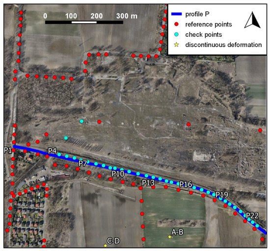
Figure 1.
Piekary site: sketch of the observation network against the background of an unmanned aerial vehicle (UAV)-derived orthomosaic.
For the Piekary Śląskie study area, the coordinates of points within the network of observation lines shown as red dots in Figure 1 were used as reference data when estimating the displacement determination accuracy. The observations, which were used to determine reference point coordinates, were obtained as two measurement series performed in parallel with the UAV missions marked Piekary 03.2016 and Piekary 09.2016. There were 93 reference points in the range of the UAV missions. Horizontal distances between reference points in the observation line network were approximately 25 m along traffic routes and 50 m in green areas.
The horizontal coordinates of the points that constituted this observation network were determined based on measurements performed using a precision total station (Leica TCRA 1102+, Canton St. Gallen, Switzerland). The total station measurements were tied to the points determined via static GNSS measurements performed using two Active Geodetic Network––European Position Determination System (ASG-EUPOS) network reference stations. The measurement vector lengths did not exceed 20 km. The RMS error in determining the horizontal coordinates of network points never exceeded 10 mm, and was less than 4 mm in most cases.
Reference point heights were determined with an accuracy of 1–2 mm (RMS error) using precision leveling (Leica DNA 03) tied to points beyond the range of the impact of mining operations. The set of reference points could be divided into 58 points located in urban areas (asphalt, concrete, and cobblestones) and 35 points located in areas covered by vegetation (meadows, green areas, wooded areas). The estimated accuracy (RMS) of displacement component determination in the XY plane for each point was not worse than 15 mm and ~3–4 mm for height.
2.2.2. The Jaworzno Site
For the Jaworzno study area, 63 points were included in the reference measurement (Figure 2). Of these, eight were measured in two series (04.2016 and 02.2020) and the others were measured only in the 02.2020 series. The points measured in both series are marked in red and identified as W1–W8 in Figure 2, while the remaining points are light blue. The distance between points on the observation lines is approximately 25 m for most points but 50 m in a few cases.
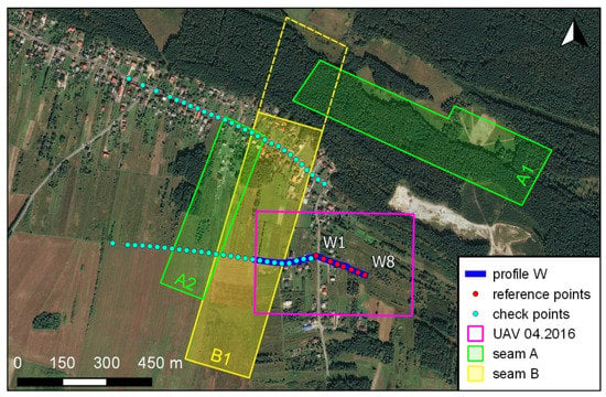
Figure 2.
Jaworzno site: sketch of the observation network used for two measurement series against the background of a UAV-derived orthomosaic and locations of mining walls in the study area.
The coordinates of the reference points in the Jaworzno 02.2020 series were determined based on GNSS RTK measurements. In addition, angular-linear measurements using a total station (Geodimeter 650 Pro, Zeiss, Oberkochen, Germany) and precision leveling (Zeiss DiNi 012, Sunnyvale, Kalifornia, USA) were performed at each point (Figure 2). The base station used for GNSS RTK measurements was tied via static GNSS measurements to two ASG-EUPOS network reference stations (KATO, KRA1), which were located ~23 km and 44 km from the measured point, respectively. As a result of this adjustment, the position determination uncertainty (RMS) for the reference points was estimated to be ~1.5–2 cm for both the XY plane and height.
The coordinates of reference points in the Jaworzno 04.2016 series were determined based only on the GNSS RTN measurements conducted in reference to the ASG-EUPOS network. The estimated accuracy (RMS) for these coordinates was about 2–3 cm in the XY plane and about 3–4 cm for height.
The estimated accuracy (RMS) of displacement component determination is not worse than 3–4 cm in the XY plane and about 4 cm in the vertical plane for each point.
2.3. Determining and Estimating the Accuracies of Coordinates Obtained Using Unmanned Aerial Vehicles (UAVs)
When acquiring and processing data from UAVs, it is assumed that each detail is visible on a minimum of three photos. However, most objects are visible on a much larger number of photos due to their large front and side overlaps. Thanks to direct measurement of pixel coordinates on many photos, it is possible to determine 3D coordinates from the intersection of several rays that converge at the measured point, i.e., using a photogrammetric intersection. This approach to determining point coordinates is called AERO in this article. However, most UAV photogrammetry users use DSMs and orthogonal processes that form orthomosaics instead of performing measurements of photos. Thus, it is possible to obtain horizontal coordinates from orthomosaics and heights from DSMs. This method of determining coordinates from UAV measurements will hereinafter be referred to as ORTO.
The advantages of ORTO measurement are speed and ease of measurement, because any geographic information system (GIS) can be used for this purpose. In general, it is always worth measuring orthomosaics because many images are used for each pixel when they are created. The AERO measurement mentioned earlier is theoretically more accurate because its data processing path is shorter in comparison with ORTO method. It includes errors in image orientation elements obtained via aerotriangulation and errors in identification and measurement of points on the images. From this point of view, ORTO measurements should produce less accurate results in relation to AERO measurement because they are performed using a data source of lower quality than photos. In addition, the accuracy of the ORTO method depends on the quality of the dense point cloud from which the DSM is generated and that is used to orthorectify the UAV images.
Coordinates of points from UAV data used in the presented research were obtained via both ORTO and AERO. This allowed us to compare the actual accuracies of both methods using the observation data and to make decisions regarding data processing optimization in later parts of the study. The accuracy analysis included a comparison of the errors of the two methods (ORTO and AERO), as determined by comparing their results to the coordinates determined via reference methods.
For the Piekary 11.2016 site, the analysis was based on the coordinates of 34 points measured via RTK GNSS. Most of these points were located along the railway embankment and thus on hard ground not covered by vegetation (Figure 1, blue dots). In the case of the Jaworzno site, an analogous analysis of coordinate determination accuracy was performed using the data from the Jaworzno 02.2020 series. In total, 63 points divided into two sets were used for the analysis: 28 points were on hard ground and 35 points were in fields (Figure 2, blue and red dots).
2.4. Determining and Estimating the Accuracies of Displacements Obtained Using UAVs
In order to estimate the uncertainties of spatial (3D) displacements determined based on UAV measurements, their values were compared to reference values. The analysis included the 93 points from the Piekary site (series 03.2016 and 09.2016) that are marked in red in Figure 1. For the Jaworzno site, displacements of eight reference points measured during both measurement series (04.2016 and 02.2020) and marked with red dots in Figure 2 were analyzed.
Only displacements were compared; point coordinates from the series were not compared. This seems justified, given the purpose of these types of measurements. In addition, not all points were visible in the UAV images (in the case of the Piekary site). In such cases, displacements of characteristic points located not more than 5 m from the measurement point were determined. Characteristic points included sewage wells, lines separating road lanes, kinks in curbs, etc.
In order to highlight the potential of the UAV photogrammetric method for both research sites, many situational details located far from existing observation lines were also identified and their horizontal displacements determined. These points generally formed an even grid over the entire research site. They were selected in such a way that they were clearly identifiable and visible on images collected for all observation series.
2.5. Identifying Discontinuous Deformations
Detection of discontinuous deformations at the Piekary site was performed via visual analysis of DSM models, DSM differential models, and orthomosaics. First, the DSMs of the first and last measurement series (03.2016 and 04.2017) were compared. Areas that indicated discontinuous deformations were verified using orthomosaics for exclusion of possible vegetation influence. Then, we searched for these discontinuous deformation areas in the intermediate series (09.2016 and 11.2016).
In the case of the Jaworzno site, extensive discontinuous deformation was identified during a field inspection at the beginning of 2009. This was confirmed via measurement of spatial observation network point displacement near the deformation. At that time, it was not possible to determine the course of this deformation and its changes over time. In 2016, UAV mission results made this analysis possible. The development of DSM provided the basis for determining the location and extent of discontinuous deformation (imaging of spatial data via the shaded relief method). Obtaining the subsidence of the ground surface based on subsequent UAV missions (04.2016 and 02.2020) made it possible to study further deformation geometry changes and their impacts on development of continuous terrain surface deformations.
3. Results
3.1. Assessment of Point Coordinate Determination Accuracy
Analysis of the results indicates that the RMS accuracy of determination of horizontal coordinates is approximately 3–5 cm at the Piekary site (Table 2) and 1.5 cm at the Jaworzno site. There is a clear correspondence between accuracy and the size of the GSD, which is about twice as large at the Piekary site as at the Jaworzno site (Table 1). It is also worth noting the lack of correlation between land cover and horizontal coordinate accuracy. The accuracies of points located in fields and on asphalt are similar.

Table 2.
RMS coordinate determination errors.
The height determination situation is different, as land cover is of some importance. For the Jaworzno site, the height determination errors for points located along an asphalt (~2 cm) are about half the size of those for points located on dirt road (~3 cm). The accuracy differences are small but noticeable here. This is probably closely related to the season in which the measurement is performed (winter) and the associated vegetation conditions.
Comparison of the accuracies of the heights of points obtained in the two research areas reveals a significant dependence on the GSD, as is noted with horizontal coordinates. The height errors are larger at the Piekary site (about 3 cm) than for comparable land cover (asphalt) at the Jaworzno site (about 2 cm).
Further analysis of the results summarized in Table 2 shows that there is no improvement in accuracy when using the AERO method of determining coordinates instead of ORTO method. In some cases, errors obtained via the ORTO method are even smaller than those from the AERO method. For this reason, it was decided to perform further analyses using only the ORTO method.
3.2. Determination and Assessment of Point Displacement Accuracy
Given the results of the analysis of coordinate determination accuracy, the analysis of displacement determination accuracy was performed using only the ORTO method. It was performed using the displacement values determined for 93 points from the Piekary site (series 03.2016 and 09.2016) and eight points from the Jaworzno site (series 04.2016 and 02.2020). During development of UAV data from the Piekary site, we were unable to determine displacements for one point located on hard ground and three points located in green areas. This means that a total of 89 points were used to calculate error values for this area. Of these, 57 were located on hard surfaces and 32 were in green areas. In the case of the Jaworzno site, the analysis was performed on all points that were observed in both series. According to the methodology applied, if it was impossible to directly indicate a point, an attempt was made to find and determine the displacement of a situational detail located within 5 m. However, it was not always possible to find such a detail. The reference values of displacements at the Piekary site ranged from 0.00 m to −1.80 m vertically and reached 0.50 m horizontally. At the Jaworzno site, reference vertical displacements ranged from −0.17 m to −0.42 m, while horizontal displacements were within the range of 0.12 m to 0.24 m. Appendix A contains Figure A1, Figure A2, Figure A3 and Figure A4 that summarize the differences between displacement values determined via the UAV photogrammetric (ORTO) and reference methods.
Table 3 presents the RMS errors of displacement determination for both sites as a function of the land cover on which the analyzed points are located. This parameter reaches approximately 1.5–2 times the GSD (Table 1) for horizontal coordinates and ~2–3 times the GSD for heights. This analysis also shows the differences associated with the characteristics of the land cover on which the point is fixed, especially in the case of height determination. The displacement determination accuracy at the Piekary site is noticeably worse in the areas covered by vegetation. This is particularly apparent from the errors of the respective vertical displacements.

Table 3.
RMS displacement determination errors.
Differences between DSMs developed for individual measurement series allow us to determine approximate subsidence value distributions. However, these subsidence values are affected by the influence of vegetation, the significance of which depends on the type, density, and vegetation cycle. Under favorable conditions, such imaging can allow us to determine the range of land surface deformation and the maximum subsidence. It also allows us to reveal possible land deformation anomalies.
Figure 3 presents differential imagery (DSM differences) of the Piekary site during the periods 03.2016–09.2016, 03.2016–11.2016, and 03.2016–04.2017. The results of this analysis may contain disturbances associated with periodic variability of the vegetation that covers the area. When creating differential images, data for which apparent uplifts exceeded 25 cm were omitted. These areas are therefore presented in white. This is clearly visible in the image of the developing subsidence basin in the north-western part of the area. Comparing the 03.2016 and 09.2016 series reveals significant gaps in data related to afforestation in the area, which was still producing vegetation gains in September. Comparison of the 03.2016 and 11.2016 series allows us to perform a wider analysis due to the partial lack of foliage, while comparing the data obtained from both series during early spring allows us to obtain the best results. The image of the subsidence basin that is formed in the south-eastern part of the study area is not significantly disturbed because of a lack of large clusters of high vegetation.
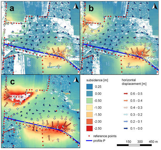
Figure 3.
Displacements determined using UAV photogrammetry at the Piekary site during: (a) 03.2016–09.2016, (b) 03.2016–11.2016, and (c) 03.2016–04.2017.
Figure 3 also presents values and directions of horizontal displacements in the form of vectors determined based on identification of characteristic situational details. These details cover the entire area of the Piekary site fairly evenly. The only exceptions to this are arable fields and meadows, where there are often no clear points. It can be assumed that the accuracy of point displacement determination is similar to that presented in Table 3. The directions and lengths of the displacement vectors correspond well to the approximate subsidence values determined via DSM differences.
Figure 4 shows DSM differences for the Jaworzno site (series 04.2016 and 02.2020). As with the Piekary site, the influence of vegetation is visible and dominates the observed subsidence values in most of the analyzed area. As the base and current series were measured in April (spring) and February (winter), respectively, the influence of vegetation is visible here with a sign that is the opposite of that noted in the Piekary site. Vegetation disturbs the subsidence values, increasing them by up to half a meter. This is particularly evident in the eastern part of the area subject to UAV measurement. As the analysis of reference measurements shows that this area is already beyond the reach of underground mining, we can easily identify these errors. The clear, almost rectilinear border between colors visible in the northwestern part of Figure 4 is the result of a discontinuous deformation in this part of the area, which manifests as a long “hump”. This deformation and its impact are described in detail in subsequent sections.
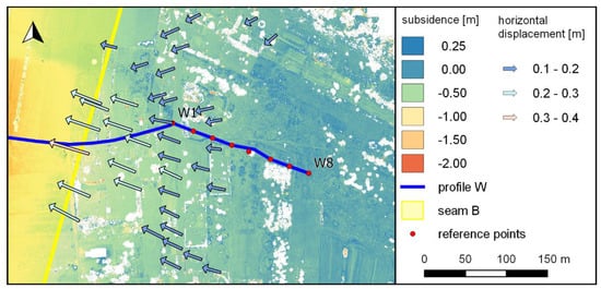
Figure 4.
Jaworzno site displacements determined using UAV photogrammetry for 04.2016–02.2020.
As with the Piekary site, horizontal displacements of selected, generally evenly distributed situational details are identified and determined. The analysis of displacement vector length and direction corresponds well to the approximate subsidence values determined from DSM differences as well as to the mining performed between the series. In this area, it is not possible to locate clear objects in agricultural and forest areas. However, finding such details in urban areas is easy.
Profiles were generated along the observation lines based on the DSMs created. These are marked with blue lines in Figure 3 and Figure 4 as profiles P and W, respectively. When processing UAV data, the profiles can be used as an additional tool to facilitate the interpretation of results. They also facilitate the assessment of noise levels in selected areas of the DSMs. Figure 5 shows a profile of changes in terrain heights at the Piekary site relative to reference data (points P1–P24). Profile line disturbances related to vegetation are clearly visible, and sometimes reach up to ±0.50 m. For most of the profile, the measurement noise associated with the accuracy of the method and the influence of vegetation does not exceed ±0.10 m.
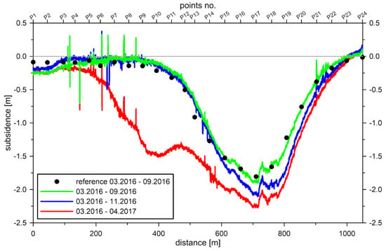
Figure 5.
A profile of Piekary site subsidence along the P profile (marked by blue line in Figure 1) based on UAV photogrammetric data is compared to reference measurements.
Figure 6 shows Jaworzno site terrain subsidence along the W line (points W1–W8). There is a clear difference between the more regular course in the western part of the subsidence profile and the eastern part, which has larger subsidence value fluctuations. The first part of the profile, which is about 200 m long, runs along a partly asphalted field road, while the remainder runs through an area covered in tall grass.
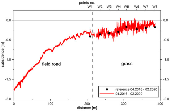
Figure 6.
A profile of Jaworzno site subsidence along the W profile (marked by blue line in Figure 2) based on UAV photogrammetric data is compared to reference measurements.
3.3. Detection of Discontinuous Deformations and Analysis of Their Development over Time
In the case of the Piekary site, the occurrence of discontinuous deformations in the form of sinkholes over voids in the rock mass produced by shallow mining of zinc and lead ores during the 19th century is common. Several such sinkholes were found in the study area during the site visit, while others were found during orthomosaic analysis. Figure 7, Figure 8, Figure 9 and Figure 10 show the development of two selected discontinuous deformations.
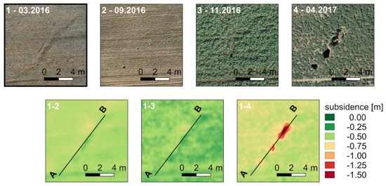
Figure 7.
Development of an A–B discontinuous deformation (Piekary site).
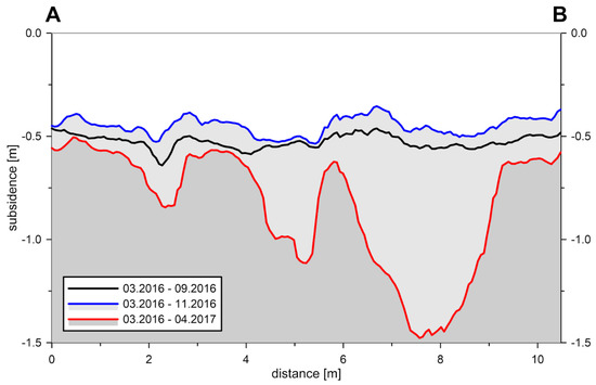
Figure 8.
Subsidence profiles along an A–B discontinuous deformation based on results obtained using UAV photogrammetry (Piekary site).
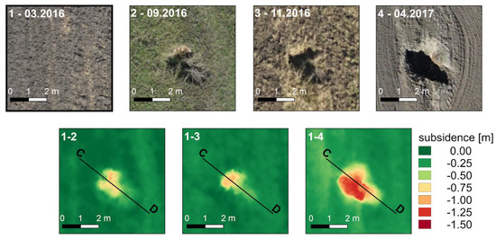
Figure 9.
Development of a C–D discontinuous deformation (Piekary site).
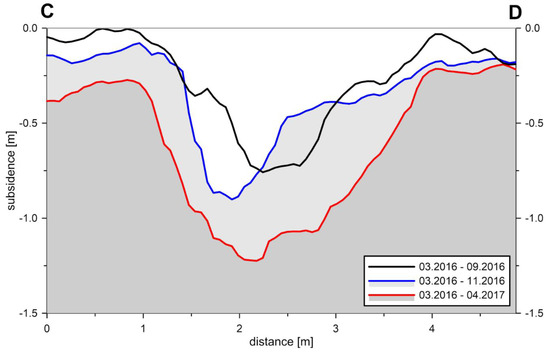
Figure 10.
Subsidence profiles along a C–D discontinuous deformation based on results obtained using UAV photogrammetry (Piekary site).
Figure 7 and Figure 8 document the development of the A–B sinkhole located in the southern part of the study area. A disturbance in the relief of the terrain associated with the developing deformation is visible in the first orthomosaic (03.2016). In the 09.2016 and 11.2016 orthomosaics, only a small sinkhole is visible. The rest of the developing deformation is effectively masked by agricultural works and vegetation. In the last series, the deformation grows and is clearly visible in both the orthomosaic and the DSM differential image despite vegetation.
The impact of vegetation on UAV documentation of this deformation is particularly visible in Figure 8. Comparison of height differences between 03.2016 and 09.2016 measurements, as well as between 03.2016 and 11.2016 measurements, may suggest an uplift of about 10 cm. However, this is the result of the presence of vegetation in the 11.2016 series, which disturbs the results. In the 04.2017 series measurement, the impact of vegetation on the measurement result becomes irrelevant due to the scale of the terrain deformation that is revealed.
The second of the discontinuous deformations denoted C–D (Figure 1) is located on the southern edge of the study area. Its development is presented in Figure 9 and Figure 10 in a manner analogous to that used before. There are no signs of a developing discontinuous deformation in the first measurement. In the 09.2016 and 11.2016 series, slow deformation development is noticeable to some extent but masked by vegetation. Orthomosaics generated based on UAV imagery collected during the 04.2017 series allow one to note significant deformation development relative to previous measurement series. These observations are confirmed in the images that show the differences between DSMs and the C–D profile created on this basis (Figure 10).
Due to the geological structure of the mining area, the Jaworzno site also exhibits a tendency towards discontinuous deformations. However, these deformations are not caused by shallow historical mining. Geophysical surveys performed in this area show that discontinuous deformations appear in places with discontinuous geological and tectonic structures. These areas also have a thin overburden layer of loose quaternary, paleogene, and neogen rocks, under which a thick bench of concise Triassic rocks dominated by limestone is located [44].
The deformation presented in Figure 11 was initially identified when deformation measurements were carried out in this area in 2009. Originally its length was estimated to be about 200 m. It has the form of a linearly extended hump. Geophysical research performed using electrical resistivity tomography suggests that this form is the result of rock mass deformation, which leads to squeezing of plastic rocks (such as clays) to fill the spaces created by specific dislocation systems (faults) or karst forms that occur within more rigid limestone blocks. Therefore, it has a completely different character and is larger than discontinuous deformations described previously. Its full range can be determined only after the UAV DSM analysis is performed (Figure 11). Repeated UAV measurements allow for analysis of changes in the geometry of this deformation.
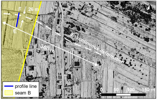
Figure 11.
A discontinuous deformation identified at the Jaworzno site using 02.2020 series data collected via UAV.
At its most visible point (E–F profile), the deformation cross section has a width of about 26 m and a relative height that ranges from 0.8 m to 1.8 m (Figure 12). To the southeast of this area, the hump dimensions decrease and the deformation gradually disappears.
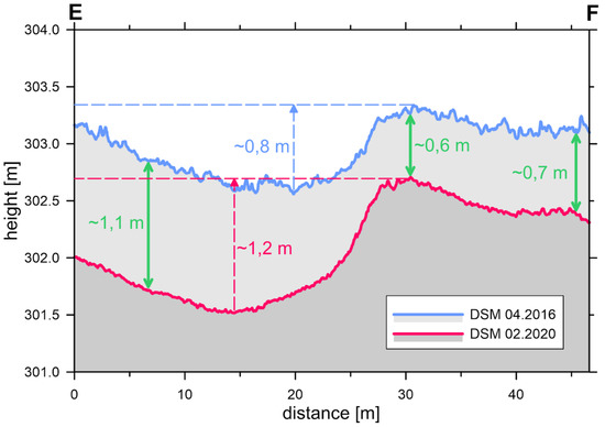
Figure 12.
Morphology of the discontinuous deformation and its cross-sectional change (E–F profiles) between 04.2016 and 02.2020 (Jaworzno site).
Changes in discontinuous deformation morphology against the background of land surface subsidence caused by underground mining in 2016–2020 are shown in Figure 12. Analyzing the terrain profiles and land surface subsidence distributions on both sides of the deformation and at the deformation site (in several cross sections) lets one identify heterogeneous deformation terrain surfaces in the deformation area. Subsidence is greater on the southern side of the hump than on the northern side. On the other hand, the deformation itself exhibits little subsidence, which may indicate further extrusion of the plastic material during discontinuous deformation formation.
4. Discussion
The accuracies of coordinate and displacement determination summarized in Table 2 and Table 3 should be treated as limit values that can be obtained only under favorable conditions. In practice, height RMS error values of two to three times the GSD are achieved only for selected points. These are objects with clear contours or areas for which the influence of vegetation is quite small or even negligible. During the development of Piekary site UAV data, it is not possible to determine the displacements using UAV-derived products for four points on the observation lines (one on hard ground and three in green areas). For these points, it is not possible to identify clear details located less than 5 m from the analyzed point. However, at the Jaworzno site, a comparison of coordinates indicates that two observation line points located on hard ground are not visible in the UAV data. When planning similar future observations, it will be necessary to ensure that points are visible on aerial images when designing classical observation lines.
A comparison of coordinate determination accuracy using the AERO and ORTO methods does not show significant differences. Given the speed of data acquisition, the use of ORTO is sufficient, especially for ground elements on roads and pavements.
In most green areas, the accuracies of terrain height and subsidence determinations are significantly burdened by the impact of vegetation. The height model obtained from the raw measurement data is DSM, not DEM. The difference in the heights between DSM and DEM often reaches tens of centimeters for meadows and fields and several meters for bushes and trees. These values are many times greater than the internal errors (noise) associated with the measurement methods themselves. The transition from DSM to DEM requires additional data processing to minimize the impact of vegetation. This approach is often referred to in the literature as vegetation filtration or ground filtering and is the subject of many past and current studies. Most of the studies performed in this field target algorithms used with LIDAR data [45,46,47,48]. However, these data have characteristics that are different from UAV photogrammetric data. On the one hand, the resolution of LIDAR data is lower. On the other hand, LIDAR data support the analysis of many reflections. For this reason, there is a need to create and develop algorithms dedicated to filtration and classification of UAV-derived point clouds [49,50,51].
When determining vertical displacements, the impact of vegetation causes systematic errors whose sign depends on the phase of the vegetation–cultivation cycle that occurs in the base series versus subsequent series. The most favorable conditions from this point of view are usually in the winter months or early spring, provided that the area is not covered with snow. The least favorable conditions with regard to determining the terrain height, and thus vertical displacement, prevail in the summer months when both the vegetation density and height are maximized. Unfortunately, the measurement periods used to monitor surface geometries are often imposed in advance. For this reason, the development and use of algorithms that can minimize the impact of vegetation is important.
Our research also allows one to estimate the accuracy with which underground mining-driven surface horizontal displacements are determined. The fact that the results obtained are promising can be seen in both the analysis of horizontal coordinates and the horizontal displacement RMS error values. Thus, one can conclude that UAV-derived photogrammetric products allow determination of horizontal displacements with an accuracy of two to three times the GSD. The values listed in Table 3 were determined using observation lines located both on hard surfaces and in areas covered with grass. However, clearly identified points are selected for the analysis. These are usually observation line points visible on orthomosaic or terrain details near a measuring point that cannot be identified effectively (or at all) on an orthomosaic.
Interesting results were also obtained when analyzing horizontal displacements against the background of differential models made via UAV-derived DSM (Figure 3 and Figure 4). The results obtained correspond well with the image of the developing subsidence basin. The points analyzed are details that are uniquely identifiable from UAV orthomosaics of various measurement series. In this way, quasi-surface data showing horizontal displacements and their changes over time are obtained. One can assume that the accuracy of the determined parameters is comparable to those produced when analyzing the observation line results. In both cases, horizontal displacements of points that could be identified clearly on orthomosaics are determined. However, finding and identifying points for these analyzes is problematic and time-consuming. The solution to this problem is the implementation of algorithms that perform automatic comparison of orthomosaics from different measurement series to determine horizontal displacements. Image-matching algorithms based on cross-correlation or feature detection (such as SIFT, SURF (speeded up robust features), ORB (oriented features from accelerated segment test (FAST), and rotated binary robust independent elementary features (BRIEF)), and BRISK (binary robust invariant scalable keypoints) may be particularly useful for this purpose [52,53,54]. However, one must consider that aforementioned algorithms were created to combine photos that are usually taken simultaneously. When analyzing orthomosaics from different measurement periods, it is necessary to solve problems related to changes in various objects over time that are not the result of mining operations. The main sources of error include vegetation, as its development and variability are associated with the growing season. For this reason, the impact of vegetation should be minimized when conducting analyzes. One of possible approaches to this problem is image segmentation. The results of this process allow for elimination of pixels with vegetation from the further processing. One can also limit the use of UAV products in horizontal displacement determination to developed areas.
Similar analyzes can be performed based on satellite images. However, their resolution is lower than that provided by UAV orthomosaics. High-resolution satellite imagery has a GSD of 0.3 m (WorldView-4), while free satellite data has significantly lower resolutions (e.g., 10 m for Sentinel). Therefore, only horizontal displacements with large values can be detected using these data.
The detection of discontinuous deformations was performed manually using DSM and orthomosaic analysis. Determining precise dimensions in the horizontal plane is possible when a change occurs but becomes difficult when an object is overgrown with vegetation. With deep, collapsed structures, it is also problematic to faithfully recreate the shape of an object’s bottom due to frequent shading of these structures during UAV missions. The clear advantages of this method with regard to detection of discontinuous deformations include the possibility of measuring a large area in a relatively short time and the lack of need for physical access to the deformation area. Considering the safety risks associated with conducting such inventories, this advantage appears important. Automated detection processes are an important field of research in discontinuous deformation detection. One possible approach is the creation of a hybrid system that combines the detection of potential discontinuous deformations via other methods, e.g., InSAR [55], with detailed verification and inventory using images obtained from UAV platforms.
Forecasting the influence of mining operations on land deformations is of fundamental importance to the safety of building structures in mining areas. These forecasts predict the sizes of continuous land surface deformations and are used to assess the risk of damage to building structures [56]. Deformation forecasts require verification as they do not consider all factors involved in deformation formation. In many cases, results from surveying of observation lines are still used for this purpose. UAV measurements allow verification of a whole deformation forecast area using points outside of existing observation networks. The ability to determine the parameters of calculation models based on this type of data can significantly improve the reliability of forecasted results. One important feature is the ability to detect anomalous deformations that deviate from the direct mining influences predicted by theoretical models.
For example, the results of UAV measurements at the Jaworzno site were subject to additional analysis via comparison with mining deformation modeling results. Model calculations were made for the period (04.2016–02.2020) for which deformations were determined using UAV measurements.
Deformation rates were calculated using Knothe model which is the most widespread in Poland [57,58]. The parameter values were determined based on subsidence recorded on observation lines at the Jaworzno site. Measurement data from 2009–2012 were used to determine the parameters.
The resulting image of model vertical and horizontal displacements (Figure 13) considers only direct and continuous impacts because Knothe’s theory only allows modeling of such deformations. Comparison of modeling and geodetic measurement results provides a basis for verification of the computational model [59] and for detection of terrain surface deformation anomalies, i.e., the occurrence of indirect influences or discontinuous deformations that result from the geological and tectonic structures of a given area.
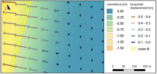
Figure 13.
Forecasted subsidence and horizontal displacement at the Jaworzno site.
The discrepancies between modeled and UAV-determined vertical and horizontal displacements are presented in Figure 14. This colored map includes subsidence differences and vectors that illustrate horizontal displacement differences. In the case of subsidence, the discrepancies between the modeled and UAV-determined values range from −0.5 m to +0.4 m. To a large extent, these discrepancies result from the impact of vegetation, but they are also affected by forecasting uncertainty [60]. However, the influence of discontinuous deformation is quite clear in the northwest section. The deformation shape detected via UAV data is much clearer than it would be if only observation lines data were used for this purpose.
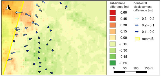
Figure 14.
Differences between forecasted and observed subsidences (color map) and horizontal displacements (differential vectors).
Comparison of the calculated and observed horizontal displacements is possible at points where displacement vectors are determined via UAV imagery analysis (see Figure 4). The difference vector lengths range from 0.01 m to 0.22 m. The changes in difference vector directions visible in Figure 14 result from the effects of discontinuous deformation. It is a barrier to deformation propagation on the surface. For this reason, the nature of the displacement on one side of this deformation is different from that noted on the other side. This can be seen by comparing the displacement vector fields in Figure 4 and Figure 13. The modeled horizontal displacement vectors generally do not change direction in the analyzed area, while the displacement vectors obtained via UAV point in different directions on opposite sides of the discontinuous deformation.
5. Conclusions
In recent years, technical and scientific advances have made UAVs increasingly inexpensive, accessible, and versatile measurement tools. The accuracies of coordinates and displacements determined based on UAV photogrammetry are already sufficient for many purposes, including surface monitoring of mining areas. UAV photogrammetry can be treated as another tool available for observation of surface geometries and their changes, especially as it allows collection of surface data.
In UAV photogrammetry, the main limitations on accuracy and the ability to use the measured data are largely associated with vegetation coverage in the monitored areas. For this reason, one important focus in the development of this technology is minimization of the impact of vegetation during processing of measurement results. Other important research directions are automation of displacement determination and discontinuous deformation detection.
This study showed that UAV photogrammetry can be used to determine many key parameters associated with the current state of land deformation caused by underground mining operations. In the coming years, dynamic development is expected to expand the range of use for this technology and further automate the processing of collected data.
Author Contributions
Conceptualization, P.Ć. and W.G.; methodology, P.Ć. and T.S.; formal analysis, P.Ć. and T.S.; investigation, P.Ć., W.G., T.S., E.P. and D.M.; resources, P.Ć., W.G., T.S., E.P., D.M., W.M., K.M., M.N., P.S. and A.W.; data curation, P.Ć.; writing—original draft preparation, P.Ć. and W.G.; writing—review and editing, P.Ć., W.G., T.S., E.P., D.M., W.M., K.M., M.N., P.S. and A.W.; visualization, D.M.; supervision, P.Ć. and W.G. All authors have read and agreed to the published version of the manuscript.
Funding
This research was funded by the research subvention of AGH University of Science and Technology, grant number 16.16.150.545.
Conflicts of Interest
The authors declare no conflict of interest.
Appendix A
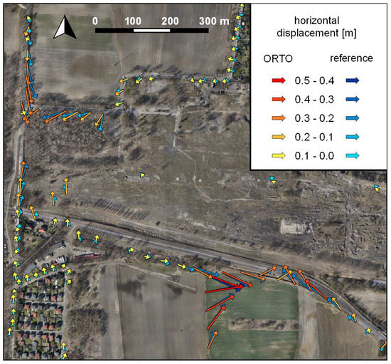
Figure A1.
Horizontal displacements determined via the UAV photogrammetric method (ORTO method) and reference measurements at the Piekary site.
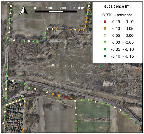
Figure A2.
Discrepancies between vertical displacements determined via the UAV photogrammetric method (ORTO method) and reference measurements at the Piekary site.
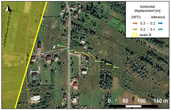
Figure A3.
Horizontal displacements determined via the UAV photogrammetric method (ORTO method) and reference measurements at the Jaworzno site.
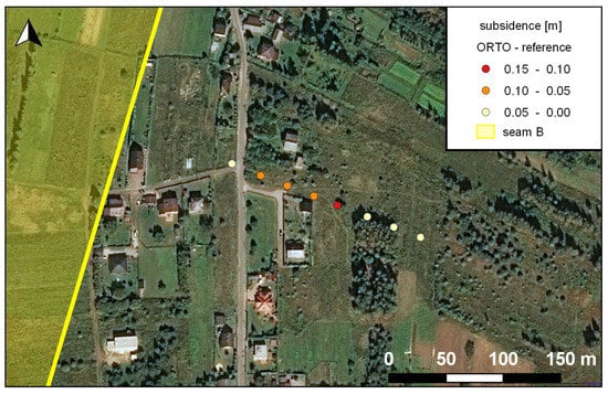
Figure A4.
Discrepancies between vertical displacements determined via the UAV photogrammetric method (ORTO method) and reference measurements at the Jaworzno site.
References
- Kratzsch, H. Mining Subsidence Engineering; Springer: Berlin/Heidelberg, Germany; New York, NY, USA, 1983; ISBN 978-3-642-81925-4. [Google Scholar]
- Bell, F.G.; Stacey, T.R.; Genske, D.D. Mining subsidence and its effect on the environment: Some differing examples. Environ. Geol. 2000, 40, 135–152. [Google Scholar] [CrossRef]
- Reddish, D.J.; Whittaker, B.N. Subsidence: Occurrence, Prediction and Control; Elsevier Science: Amsterdam, The Netherlands, 2012; ISBN 9780444598349. [Google Scholar]
- Ren, F.; Zhang, D.; Cao, J.; Yu, M.; Li, S. Study on the Rock Mass Caving and Surface Subsidence Mechanism Based on an in Situ Geological Investigation and Numerical Analysis. Math. Probl. Eng. 2018, 2018, 1–18. [Google Scholar] [CrossRef]
- Rusek, J. The point nuisance method as a decision-support system based on Bayesian inference approach. Arch. Min. Sci. 2020, 65, 117–127. [Google Scholar]
- Peng, S.S.; Ma, W.M.; Zhong, W.L. Surface Subsidence Engineering; Society for Mining, Metallurgy, and Exploration: Littleton, CO, USA, 1992; ISBN 0873351142. [Google Scholar]
- Stoch, T. Hirizontal Displacement in Mining Area Protection; AGH University of Science and Technology Press: Kraków, Poland, 2019; ISBN 978-83-66364-19-6. [Google Scholar]
- Blachowski, J.; Jiránková, E.; Lazecký, M.; Kadlečík, P.; Milczarek, W. Application of satellite radar interferometry (PSInSAR) in analysis of secondary surface deformations in mining areas. Case studies from Czech Republic and Poland. Acta Geodyn. Geomater. 2018, 15, 173–185. [Google Scholar] [CrossRef]
- Ilieva, M.; Polanin, P.; Borkowski, A.; Gruchlik, P.; Smolak, K.; Kowalski, A.; Rohm, W. Mining deformation life cycle in the light of InSAR and deformation models. Remote Sens. 2019, 11, 745. [Google Scholar] [CrossRef]
- Pawluszek-Filipiak, K.; Borkowski, A. Integration of DInSAR and SBAS Techniques to Determine Mining-Related Deformations Using Sentinel-1 Data: The Case Study of Rydułtowy Mine in Poland. Remote Sens. 2020, 12, 242. [Google Scholar] [CrossRef]
- Malinowska, A.A.; Witkowski, W.T.; Guzy, A.; Hejmanowski, R. Mapping ground movements caused by mining-induced earthquakes applying satellite radar interferometry. Eng. Geol. 2018, 246, 402–411. [Google Scholar] [CrossRef]
- Milczarek, W. Application of a Small Baseline Subset Time Series Method with Atmospheric Correction in Monitoring Results of Mining Activity on Ground Surface and in Detecting Induced Seismic Events. Remote Sens. 2019, 11, 1008. [Google Scholar] [CrossRef]
- Rudziński, Ł.; Mirek, K.; Mirek, J. Rapid ground deformation corresponding to a mining-induced seismic event followed by a massive collapse. Nat. Hazards 2019, 96, 461–471. [Google Scholar] [CrossRef]
- Popiołek, E.; Ostrowski, J.; Czaja, J.; Mazur, J. The impact of a strong mining tremor on the subsidence of the area surface in the Legnica-Glogow Copper Area. In Proceedings of the 10th FIG International Symposium on Deformation Measurements, International Federation of Surveyors, Orange, CA, USA, 19–22 March 2001; pp. 77–80. [Google Scholar]
- Szczerbowski, Z.; Jura, J. Mining induced seismic events and surface deformations monitored by GPS permanent stations. Acta Geodyn. Geomater. 2015, 12, 237–248. [Google Scholar] [CrossRef]
- Sowter, A.; Bateson, L.; Strange, P.; Ambrose, K.; Fifiksyafiudin, M. Dinsar estimation of land motion using intermittent coherence with application to the south derbyshire and leicestershire coalfields. Remote Sens. Lett. 2013, 4, 979–987. [Google Scholar] [CrossRef]
- Bernardino, P.; Fornaro, G.; Lanari, R.; Sansosti, E. A new algorithm for surface deformation monitoring based on small baseline differential SAR interferograms. IEEE Trans. Geosci. Remote Sens. 2002, 40, 2375–2383. [Google Scholar] [CrossRef]
- Cigna, F.; Sowter, A. The relationship between intermittent coherence and precision of ISBAS InSAR ground motion velocities: ERS-1/2 case studies in the UK. Remote Sens. Environ. 2017, 202, 177–198. [Google Scholar] [CrossRef]
- Yu, H.; Lu, X.; Cheng, G.; Ge, X. Detection and volume estimation of mining subsidence based on multi-temporal LiDAR data. In Proceedings of the 2011 19th International Conference on Geoinformatics, Shanghai, China, 24–26 June 2011; pp. 1–6. [Google Scholar]
- Lian, X.; Hu, H. Terrestrial laser scanning monitoring and spatial analysis of ground disaster in Gaoyang coal mine in Shanxi, China: A technical note. Environ. Earth Sci. 2017, 76, 287. [Google Scholar] [CrossRef]
- Ao, J.; Wu, K.; Wang, Y.; Li, L. Subsidence Monitoring Using Lidar and Morton Code Indexing. J. Surv. Eng. 2016, 142, 6015002. [Google Scholar] [CrossRef]
- Gu, Y.; Zhou, D.; Zhang, D.; Wu, K.; Zhou, B. Study on subsidence monitoring technology using terrestrial 3D laser scanning without a target in a mining area: An example of Wangjiata coal mine, China. Bull. Eng. Geol. Environ. 2020, 1–9. [Google Scholar] [CrossRef]
- Yu, H.; Lu, X.; Ge, X.; Cheng, G. Digital terrain model extraction from airborne LiDAR data in complex mining area. In Proceedings of the 2010 18th International Conference on Geoinformatics, Beijing, China, 18–20 June 2010; pp. 1–6. [Google Scholar]
- Song, B.; Zheng, N.; Li, D.; Chen, R.; Li, L. Reconstructing DEM using TLS point cloud data and NURBS surface. Trans. Nonferrous Met. Soc. China 2015, 25, 3165–3172. [Google Scholar] [CrossRef]
- Brede, B.; Lau, A.; Bartholomeus, H.M.; Kooistra, L. Comparing RIEGL RiCOPTER UAV LiDAR derived canopy height and DBH with terrestrial LiDAR. Sensors 2017, 17, 2371. [Google Scholar] [CrossRef]
- Ren, H.; Zhao, Y.; Xiao, W.; Hu, Z. A review of UAV monitoring in mining areas: Current status and future perspectives. Int. J. Coal Sci. Technol. 2019, 6, 320–333. [Google Scholar] [CrossRef]
- Gasperini, D.; Allemand, P.; Delacourt, C.; Grandjean, P. Potential and limitation of UAV for monitoring subsidence in municipal landfills. Int. J. Environ. Technol. Manag. 2014, 17, 1–13. [Google Scholar] [CrossRef]
- Stupar, D.I.; Rošer, J.; Vulić, M. Investigation of unmanned aerial vehicles-based photogrammetry for large mine subsidence monitoring. Minerals 2020, 10, 186. [Google Scholar]
- Zhou, D.; Qi, L.; Zhang, D.; Zhou, B.; Guo, L. Unmanned Aerial Vehicle (UAV) Photogrammetry Technology for Dynamic Mining Subsidence Monitoring and Parameter Inversion: A Case Study in China. IEEE Access 2020, 8, 16372–16386. [Google Scholar]
- Pal, A.; Rošer, J.; Vulić, M. Surface Subsidence Prognosis above an Underground Longwall Excavation and Based on 3D Point Cloud Analysis. Minerals 2020, 10, 82. [Google Scholar] [CrossRef]
- Streutker, D.R.; Glenn, N.F. LiDAR measurement of sagebrush steppe vegetation heights. Remote Sens. Environ. 2006, 102, 135–145. [Google Scholar] [CrossRef]
- Tong, X.; Liu, X.; Chen, P.; Liu, S.; Luan, K.; Li, L.; Liu, S.; Liu, X.; Xie, H.; Jin, Y.; et al. Integration of UAV-based photogrammetry and terrestrial laser scanning for the three-dimensional mapping and monitoring of open-pit mine areas. Remote Sens. 2015, 7, 6635–6662. [Google Scholar] [CrossRef]
- Ge, L.; Li, X.; Ng, A.H. UAV for mining applications: A case study at an open-cut mine and a longwall mine in New South Wales, Australia. In Proceedings of the 2016 IEEE International Geoscience and Remote Sensing Symposium (IGARSS), Beijing, China, 10–15 July 2016; pp. 5422–5425. [Google Scholar]
- Dang, K.; Sassa, K.; Fukuoka, H.; Sakai, N.; Sato, Y.; Takara, K.; Quang, L.H.; Loi, D.H.; Van Tien, P.; Ha, N.D. Mechanism of two rapid and long-runout landslides in the 16 April 2016 Kumamoto earthquake using a ring-shear apparatus and computer simulation (LS-RAPID). Landslides 2016, 13, 1525–1534. [Google Scholar] [CrossRef]
- Hsieh, Y.C.; Chan, Y.C.; Hu, J.C. Digital elevation model differencing and error estimation from multiple sources: A case study from the Meiyuan Shan landslide in Taiwan. Remote Sens. 2016, 8, 199. [Google Scholar] [CrossRef]
- Lindner, G.; Schraml, K.; Mansberger, R.; Hübl, J. UAV monitoring and documentation of a large landslide. Appl. Geomat. 2016, 8, 1–11. [Google Scholar] [CrossRef]
- Rossi, G.; Tanteri, L.; Tofani, V.; Vannocci, P.; Moretti, S.; Casagli, N. Multitemporal UAV surveys for landslide mapping and characterization. Landslides 2018, 15, 1045–1052. [Google Scholar] [CrossRef]
- Yu, M.; Huang, Y.; Zhou, J.; Mao, L. Modeling of landslide topography based on micro-unmanned aerial vehicle photography and structure-from-motion. Environ. Earth Sci. 2017, 76, 520. [Google Scholar] [CrossRef]
- Wang, D.; Wang, Z.; Li, Y.; Fan, T.; Ouyang, C.; Ji, F. Characteristics and dynamic process analysis of the 2018 Mabian consequent landslide in Sichuan Province, China. Bull. Eng. Geol. Environ. 2020, 1–23. [Google Scholar] [CrossRef]
- Maciuk, K.; Lewińska, P. High-rate monitoring of satellite clocks using two methods of averaging time. Remote Sens. 2019, 11, 2754. [Google Scholar] [CrossRef]
- Stoch, T. Spatial observation network for measuring surface deformation in mining areas. In Proceedings of the Wyd. Monograficzne Konferencji: X Dni Miernictwa Górniczego i Ochrony Terenów Górniczych, Kraków, Poland, 28–29 May 2009; pp. 387–394. [Google Scholar]
- Maciuk, K. Satellite clock stability analysis depending on the reference clock type. Arab. J. Geosci. 2019, 12, 28. [Google Scholar] [CrossRef]
- Ćwiąkała, P. Testing procedure of unmanned aerial vehicles (UAVs) trajectory in automatic missions. Appl. Sci. 2019, 9, 3488. [Google Scholar] [CrossRef]
- Niedojadło, Z.; Piwowarski, W.; Mościcki, W.; Sopata, P.; Stoch, T.; Bania, G.; Ćwiklik, M. The impact of local surface geological structure on ground deformation under the conditions of underground mining exploitation. Przegląd Górniczy 2016, 72, 18–26. [Google Scholar]
- Şerifoğlu Yilmaz, C.; Güngör, O. Comparison of the performances of ground filtering algorithms and DTM generation from a UAV-based point cloud. Geocarto Int. 2018, 33, 522–537. [Google Scholar] [CrossRef]
- Şerifoğlu Yilmaz, C.; Yilmaz, V.; Güngör, O. Investigating the performances of commercial and non-commercial software for ground filtering of UAV-based point clouds. Int. J. Remote Sens. 2018, 39, 5016–5042. [Google Scholar] [CrossRef]
- Zhang, Z.; Gerke, M.; Vosselman, G.; Yang, M.Y. Filtering Photogrammetric Point Clouds Using Standard Lidar Filters Towards Dtm Generation. ISPRS Ann. Photogramm. Remote Sens. Spat. Inf. Sci. 2018, 4, 319–326. [Google Scholar] [CrossRef]
- Zeybek, M.; Şanlıoğlu, İ. Point cloud filtering on UAV based point cloud. Measurement 2019, 133, 99–111. [Google Scholar] [CrossRef]
- Gruszczyński, W.; Matwij, W.; Ćwiąkała, P. Comparison of low-altitude UAV photogrammetry with terrestrial laser scanning as data-source methods for terrain covered in low vegetation. ISPRS J. Photogramm. Remote Sens. 2017, 126, 168–179. [Google Scholar] [CrossRef]
- Yilmaz, V.; Konakoglu, B.; Serifoglu, C.; Gungor, O.; Gökalp, E. Image classification-based ground filtering of point clouds extracted from UAV-based aerial photos. Geocarto Int. 2018, 33, 310–320. [Google Scholar] [CrossRef]
- Gruszczyński, W.; Puniach, E.; Ćwiąkała, P.; Matwij, W. Application of convolutional neural networks for low vegetation filtering from data acquired by UAVs. ISPRS J. Photogramm. Remote Sens. 2019, 158, 1–10. [Google Scholar] [CrossRef]
- Debella-Gilo, M.; Kääb, A. Sub-pixel precision image matching for measuring surface displacements on mass movements using normalized cross-correlation. Remote Sens. Environ. 2011, 115, 130–142. [Google Scholar] [CrossRef]
- Tareen, S.A.K.; Saleem, Z. A comparative analysis of SIFT, SURF, KAZE, AKAZE, ORB, and BRISK. In Proceedings of the 2018 International Conference on Computing, Mathematics and Engineering Technologies (iCoMET), Sukkur, Pakistan, 3–4 March 2018. [Google Scholar]
- Liu, C.; Liu, H.; Liu, Y.; Li, T.; Wang, T. Normalized cross correlation image stitching algorithm based on minimum spanning tree. Optik 2019, 179, 610–616. [Google Scholar] [CrossRef]
- Malinowska, A.A.; Witkowski, W.T.; Hejmanowski, R.; Chang, L.; van Leijen, F.J.; Hanssen, R.F. Sinkhole occurrence monitoring over shallow abandoned coal mines with satellite-based persistent scatterer interferometry. Eng. Geol. 2019, 262, 105336. [Google Scholar] [CrossRef]
- Firek, K.; Rusek, J. Partial least squares method in the analysis of the intensity of damage in prefabricated large-block building structures. Arch. Min. Sci. 2017, 62, 269–277. [Google Scholar] [CrossRef][Green Version]
- Knothe, S. Observations of surface movements under influence of mining and their theoretical interpretation. In Proceedings of the European Congress on Ground Movement, Leeds, UK, 9–12 April 1957; pp. 210–218. [Google Scholar]
- Malinowska, A.; Hejmanowski, R.; Dai, H. Ground movements modeling applying adjusted influence function. Int. J. Min. Sci. Technol. 2020, 30, 243–249. [Google Scholar] [CrossRef]
- Kwinta, A.; Gradka, R. Analysis of the damage influence range generated by underground mining. Int. J. Rock Mech. Min. Sci. 2020, 128, 104263. [Google Scholar] [CrossRef]
- Gruszczyński, W.; Niedojadło, Z.; Mrocheń, D. Influence of model parameter uncertainties on forecasted subsidence. Acta Geodyn. Geomater. 2018, 15, 211–228. [Google Scholar] [CrossRef]
© 2020 by the authors. Licensee MDPI, Basel, Switzerland. This article is an open access article distributed under the terms and conditions of the Creative Commons Attribution (CC BY) license (http://creativecommons.org/licenses/by/4.0/).