Article

3D Registration and Integrated Segmentation Framework for Heterogeneous Unmanned Robotic Systems

1
Department of Mechanics, Royal Military Academy, 1000 Brussels, Belgium
2
Department of Automatic Control and Electronics, Faculty of Electrical Engineering, 71000 Sarajevo, Bosnia and Herzegovina
3
ITS Research and Technology, AVL List GmbH, 8010 Graz, Austria
4
Department of Electrical Engineering and Information Technology, University of Naples Federico II, 80125 Napoli, Italy
*
Author to whom correspondence should be addressed.
Remote Sens. 2020, 12(10), 1608; https://doi.org/10.3390/rs12101608
Submission received: 13 March 2020 / Revised: 3 May 2020 / Accepted: 8 May 2020 / Published: 18 May 2020
(This article belongs to the Special Issue Advances and Innovative Applications of Unmanned Aerial Vehicles)

Abstract

:
The paper proposes a novel framework for registering and segmenting 3D point clouds of large-scale natural terrain and complex environments coming from a multisensor heterogeneous robotics system, consisting of unmanned aerial and ground vehicles. This framework involves data acquisition and pre-processing, 3D heterogeneous registration and integrated multi-sensor based segmentation modules. The first module provides robust and accurate homogeneous registrations of 3D environmental models based on sensors’ measurements acquired from the ground (UGV) and aerial (UAV) robots. For 3D UGV registration, we proposed a novel local minima escape ICP (LME-ICP) method, which is based on the well known iterative closest point (ICP) algorithm extending it by the introduction of our local minima estimation and local minima escape mechanisms. It did not require any prior known pose estimation information acquired from sensing systems like odometry, global positioning system (GPS), or inertial measurement units (IMU). The 3D UAV registration has been performed using the Structure from Motion (SfM) approach. In order to improve and speed up the process of outliers removal for large-scale outdoor environments, we introduced the Fast Cluster Statistical Outlier Removal (FCSOR) method. This method was used to filter out the noise and to downsample the input data, which will spare computational and memory resources for further processing steps. Then, we co-registered a point cloud acquired from a laser ranger (UGV) and a point cloud generated from images (UAV) generated by the SfM method. The 3D heterogeneous module consists of a semi-automated 3D scan registration system, developed with the aim to overcome the shortcomings of the existing fully automated 3D registration approaches. This semi-automated registration system is based on the novel Scale Invariant Registration Method (SIRM). The SIRM provides the initial scaling between two heterogenous point clouds and provides an adaptive mechanism for tuning the mean scale, based on the difference between two consecutive estimated point clouds’ alignment error values. Once aligned, the resulting homogeneous ground-aerial point cloud is further processed by a segmentation module. For this purpose, we have proposed a system for integrated multi-sensor based segmentation of 3D point clouds. This system followed a two steps sequence: ground-object segmentation and color-based region-growing segmentation. The experimental validation of the proposed 3D heterogeneous registration and integrated segmentation framework was performed on large-scale datasets representing unstructured outdoor environments, demonstrating the potential and benefits of the proposed semi-automated 3D registration system in real-world environments.

1. Introduction

The registration of 3D point clouds of outdoor environments is an important aspect in field robotics. In the past few years, many research efforts have been made to improve the performance and capabilities of the existing registration methods. The main concern is to obtain a more accurate and complete 3D model of the outdoor environment based on a fusion of data taken from different sensors as well as from different heterogeneous multi-robot systems [1,2]. The high complexity of outdoor environments poses a special challenge for the existing autonomous robotic technologies. One of the main challenges of such a task is the optimal and timely fusion of 3D data in order to improve the perception capabilities and the scene understanding. Particular attention is paid to exploit the advantages of deploying ground and aerial robotic platforms equipped with different perceptual sensor systems.
The potential of deploying heterogeneous multi-robot systems composed of UAVs and UGVs could have an important benefit in various application scenarios, ranging from military to commercial applications [3]. Aforementioned systems increasingly attract the focus of the research and robotics community, especially because of the many advantages which could be achieved by merging the capabilities of each vehicle into a singular collaborative system [4]. This can be especially true in complex and difficult safety-critical applications like search and rescue missions. The value of such a heterogeneous robot system in a disaster scenario has been presented in [5], where important tasks are the exploration, perception, and mapping of an unknown environment in timely sensitive manner. These tasks could also be accomplished also by deploying a single vehicle, either a ground or an aerial system. However, each platform imposes its own limitations. The ground vehicles can sometimes be incapable of traversing and perceiving the entire environment with limited or even unviewable vantage points. On the other hand, the aerial systems typically have limited payload capacities and can only operate during short time durations. Each of the robotic platforms also has its own advantages. The ground robots can interact with the environment, support a higher weight and thus typically more sophisticated sensor payloads, and they have the capability to execute longer-duration missions (often for multiple hours) because of their larger battery capacity. The main advantages of the aerial robots are that they can be used in order to traverse the environment more easily and provide a better vantage point.
It is clear that complex operations such as search and rescue missions could be more efficiently accomplished by combining these single robots into a heterogeneous team [6]. Such a configuration can often achieve a complementary increase in the performance and may be better balanced to obtain higher quality and more complete information while guaranteeing robustness to the challenges imposed by the hard environmental conditions in the search and rescue context. Using an aerial robot, we can obtain a dense 3D model of the area on a larger scale, the acquisition time is shorter, and data of the larger environment can be acquired with more rich information like texture. The ground 3D model, collected with the ground robot, allows us to generate more accurate 3D models of the environment, but for a smaller-scale area [7,8]. A logical step would be to fuse these two point clouds into one comprehensive environmental representation.
The problem of fusing data coming from different robotic platforms and sensors, with the aim to generate consistent 3D models, is becoming increasingly widespread within the research community [7,9,10]. In our paper, we will introduce the 3D heterogeneous registration and integrated segmentation framework for co-registering and segmenting 3D maps data coming from a heterogeneous UGV-UAV systems. The proposed framework is generic in the sense that it can accept any kind of 3D data from aerial and ground based robotic systems. The most widespread purpose for the fusion of ground and aerial based data is to increase the accuracy and completeness of the generated 3D map, since the data are combined from a ground and aerial point of view. Once aligned, the global map is used to perform more high-level processing tasks like ground object segmentation and color segmentation. The process of fusing two heterogeneous 3D datasets is a challenging task. In order to overcome the limitations of dealing with 3D data sets coming from different sensor systems (lasers, cameras) and different perspectives of the environment (ground-UGV and air-UAV), we propose an automated and robust 3D registration process based on the Scale Invariant Registration Method (SIRM) with scale adaptation and fine point cloud alignment, allowing us to consistently align two or more heterogeneous point clouds. The novelty of this method lies in its capability to cope with an arbitrary scale difference between the point clouds, without any information about their initial position and orientation. Furthermore, the SIRM method does not require having a good initial overlap between two heterogeneous datasets. That is one of the advantage of the SIRM method over most pairwise registration and groupwise registration algorithms [8,11,12] which require a rough pre-alignment of the different point sets. Moreover, the proposed SIRM method is robust to errors in the process of selecting the corresponding pairs of points in both point clouds.
In the case of 3D point cloud generation from the UGV, the matching and displacement estimation of two consecutive point cloud measurements are solved in our paper by our novel method named Local Minima Escape ICP (LME-ICP). It allows a fast and accurate registration of 3D models of large-scale outdoor environments without any prior known pose estimation information acquired from sensing systems. The main advantage of LME-ICP method over other existing ICP based methods is its ability to estimate the local minima from the new environmental scan and escape from them in case of unstructured large-scale outdoor environments. Due to the open loop and iterative nature of the ICP algorithm, it is not possible to guarantee the avoidance of local minima [7]. Recently, there have been some efforts in solving the local minima problem, as presented in [13] and [14]. These approaches produce an accurate 3D map of outdoor environments with detecting and escaping from local minima situations. However, they are used for smaller environments. In contrast to above-mentioned approaches, our proposed LME-ICP method provides a precise 3D model of large-scale outdoor environments for sufficient larger number of points (over 31,000,000) with efficient local minima detection and escape. The performance of this method was verified along a comparison with several ICP based methods. In addition, we have validated our framework with reference ground truth data calculated with high accuracy geodetic precision.
In order to improve 3D registration process, the effective algorithm for detecting and removing outliers in 3D input scans is introduced in this paper. The presence of outliers represents a significant problem for automated 3D laser scanning system [15]. The 3D model obtained from the point clouds with outliers typically misses many details and/or reconstructs wrong geometry. It is very important to provide a fast outliers detection in 3D input scans prior to the filtering of points in the point cloud due to negative effects which outliers have on the output of filtering algorithms. The main shortcomings of traditional methods are coping with a high dimensionality of the data in large 3D point clouds and satisfying real-time requirements for the outliers removal in the large 3D point clouds [16]. Our proposed filtering algorithm includes the Voxel-subsampling and Fast Cluster Statistical Outlier Removal (FCSOR) approaches. The introduced FCSOR represents an extension of the Statistical Outliers Removal (SOR) method [17]. The FCSOR simultaneously provides improvement of the accuracy and the computational tractability of the widely used SOR method. Therefore, it is time efficient for outlier analysis and removal in arbitrary large datasets, including millions of points. This filtering process eliminates the erroneous points provided by the scanner: points generated at infinity (spread points), outliers (points outside the scene), and noise (due to reflections and shiny surfaces).
The 3D registration process using the measurements of UAV sensors is based on the well known Structure from Motion (SfM) approach. The SfM algorithm is designed to extract 3D relief information and generate a point cloud of the environment based on the matched features from a set of acquired overlapping images [18]. Once aligned, the resulting homogeneous ground-aerial point cloud is further processed by a segmentation module. For this purpose, we developed a system for integrated multi-sensor based segmentation of 3D point clouds. This system follows a two-step sequence: ground-object segmentation and color-based region-growing segmentation. It should be underlined that our heterogeneous system is fully independent. While many of the existing approaches are more focused on the collaboration between the aerial and ground robots [19,20,21], our focus is on the data fusion of the cluttered 3D spaces. Experimental validation is performed within an unstructured outdoor environment, demonstrating that the proposed 3D matching pipeline efficiently overcomes the constraints of the different sensor systems and different vantage points of the environment and thereby demonstrating its usefulness in large-scale real-world environments.
There are many areas of application where the proposed heterogeneous 3D registration system can be exploited, such as agriculture, cultural heritage, safety-critical applications, civil protection, military applications, etc. Our registration system can be used for damage detection in cultural heritage, an inspection and diagnosis of heritage constructions, structural condition assessment, etc. In the case of safety-critical and civil protection applications, it could be employed for different search and rescue missions, e.g., rescue of persons from collapsed buildings, wildfire detection, detection and disposal of mines, monitoring an area for intruders, etc. The potential military applications of our registration system involve border surveillance, ground reconnaissance, and offensive missions.

2. Related Work

In recent years, there have been significant achievements and contributions in the domain of multi-robot systems. The interest in this field is motivated by several advantages that such systems exploit in comparison to a single robot system, i.e., tasks can be executed more efficiently by a team than by a single robot. Indeed, using multiple robots increases robustness through fault tolerance or taking advantage of distributed perception and motion possibilities [4]. Therefore, this heterogeneous system can achieve a promising performance and higher quality, acquiring more complete information of the environment versus individual robot. The focus in our work will be on heterogenoeus system which consist of aerial and ground-based robots. A lot of research has been performed in this field, aiming to combine the strengths of the unmanned aerial vehicles and unmanned ground vehicles [22,23,24]. Cooperation approaches where the ground vehicle uses the data gathered by the aerial vehicle have been proposed in [25]. In the research proposed by [25], the aerial platform is used as an eye in the sky acquiring the data from above and providing a global view for the ground vehicle. With the aerial data, the traversability analysis and path planning are computed for the ground vehicle. Besides the perception tasks, heterogeneous aerial and ground vehicles have been deployed in a cooperative manner manipulating objects in an industrial environment. This work has been presented in [26], where a group of ground robots are guided by an aerial vehicle and a human operator, moving in a coordinated way in a formation, while carrying objects within an industrial area. Although deploying a group of heterogeneous aerial and ground vehicles has become an extensive topic within the research community, very little research has addressed the problem of fusing the 3D data coming from different types of robotics platforms as well as from different sensors.
The 3D map registration is a challenging problem when dealing with heterogeneous UGV-UAV robots [1,27,28]. These robots are of different sizes, shapes, and with different sense-act capabilities. The problems of registering ground and aerial 3D point clouds are related to the different vantage perspectives of the ground and aerial robots. Another problem is the different spatial resolution obtained by the heterogeneous perception systems [1,7,13]. In our case, two different sensor modalities are used: a lidar rangefinder (UGV) and a digital camera (UAV). Having in mind the different spatial resolution levels, it is not possible to have a single point to point registration; it is a one to many registration approach. Nevertheless, efforts of combining 3D data from heterogeneous robots is under research and not adequately addressed. An example of an indoor scenario has been demonstrated in [5], showing the advantages of using a heterogeneous robotic system in a disaster situation (earthquake-damaged building). A team of aerial and ground vehicles are performing a collaborative 3D mapping of the building indoors. The task was successfully accomplished and the team of robots was able to provide an insight in the degree of damage which affected the building.
Nevertheless, the problem gets more complex if the heterogeneous systems are deployed outdoors in a large-scale unstructured environment, which is targeted as a validation environment for our proposed work. In that context, some work has been proposed in [27], where the authors introduced a method for localization of the unmanned aerial vehicle with respect to the ground vehicle in close range. It provides a global alignment of the aerial and ground point clouds based on the Monte Carlo localization. Their proposed method requires an overlap between the aerial and ground maps and a 3D structure in the scene. Another limitation factor is that, for a completely flat environment, the method does not converge. The validation of the proposed system is done for an outdoor environment without information about its size and complexity, where the registration accuracy is not provided. Some of the current rear algorithms that deal with a problem of 3D registration of outdoor environment based on heterogeneous UGV and UAV point clouds are presented in [1,29]. In [1], authors address cooperative UAV-UGV environment reconstruction problem in agricultural scenarios. The introduced approach built upon a multimodal environment representation that uses the semantics and the geometry of the target field, and a data association strategy solved as a LDOF problem. The framework for the automated registration of heterogeneous point clouds using 2D local feature points in the images taken from UAVs and UGVs was presented in [29]. These point clouds were initially scaled and registered with a transformation matrix computed from the 3D points corresponding to the 2D feature matching points. The initially aligned point clouds were subsequently adjusted by the ICP algorithm. Our proposed framework successfully handles the limitations for an overlap between the aerial and ground point clouds, and it is also not dependent on any environmental characteristics. It is capable of dealing with a large-scale outdoor environments with high geometrical accuracy, as validated with ground-truth data.
Therefore, for any type of the registration technique, when there is a weak overlap between the two data scans, a probable convergence to the local minima is impossible to avoid. It is evident that, in a local minimum situation, the registration of the data scans does not correspond to a good alignment. A possible approach for solving the local minima would be an effective initial estimation (e.g., odometry of the robot) of the transformation. However, it is not an easy task to guarantee that an initial estimation is a good one, especially when we are dealing with unstructured outdoor environments. There are some efforts of solving the local minima problem, as proposed in [13] with a global optima ICP (Go-ICP) solution. However, due to the high computational requirements, this method is not useful for large-scale outdoor environment data sets. Enhanced ICP registration system to achieve optimal registration based on early warning mechanism to perceive the local minimum and a heuristic escape scheme is introduced in [14]. The performance of this system was verified for outdoor environment represented by at most 212,000 points.
Furthermore, the appearance of a noise and outliers in point clouds causes serious problems in reconstruction of 3D environmental model, especially for the large-scale environments with rough terrain. It is very important to detect outliers in 3D input scans prior to the filtering of points in the point cloud due to negative effects which have outliers on the output of traditional filtering algorithms [30]. Wavelet transformations and AI based methods can be an alternatives to the traditional methods. In order to identify outliers, the wavelet-based methods transform the space and find them in the non-dense regions in transformed space [31]. In the field of AI, the following methods are mostly used: neural networks [32], support vector machines [33] and fuzzy logic [34]. The main advantage of these methods is requiring poor or no a priori assumption on the considered data in datasets.
In our approach, we have designed and implemented a registration pipeline for aligning 3D maps coming from a heterogeneous robotics system (UGV and UAV). The aerial map is generated using a photogrammetric structure from a motion approach, taking as an input a set two-dimensional digital image sequences and as a final output a three-dimensional scene reconstruction. The ground vehicle provides a 3D-map using an on-board lidar rangefinder. The two heterogeneous maps are combined into a consistent global map providing an extended view over the large-scale outdoor environment.

3. 3D Heterogeneous Registration and Integrated Segmentation

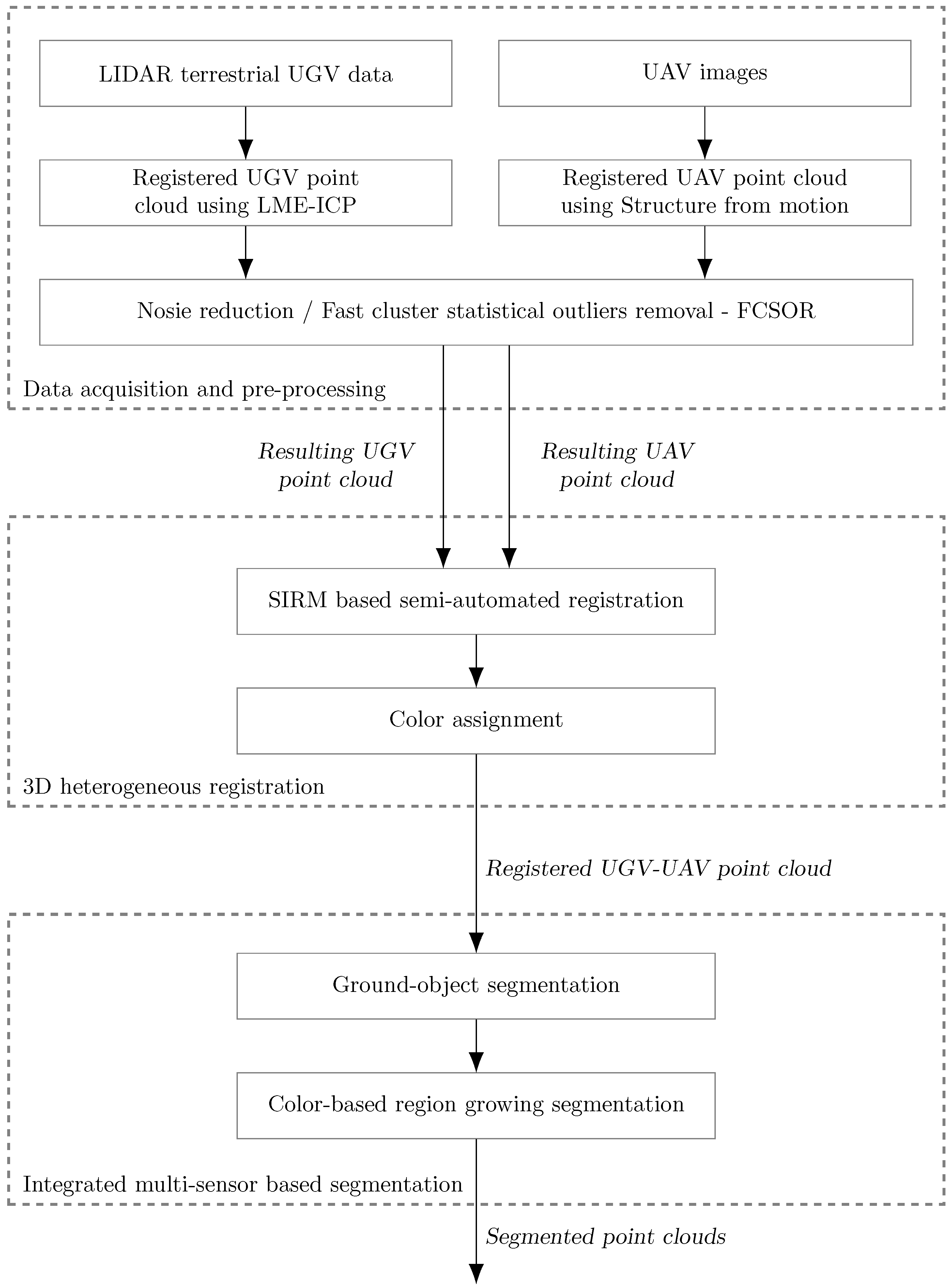
This section presents the overall proposed architecture for the 3D registration and segmentation framework as shown in (Figure 1) enabling the alignment of the data coming from heterogeneous robots and sensors. The proposed framework is briefly elaborated here, showing the pipeline of the algorithm, whereas detailed descriptions of the framework parts will be given in Section 4, Section 5 and Section 6. The proposed 3D registration framework involves the following three-step process:
  • Data acquisition and pre-processing,
  • Semi-automated UGV-UAV 3D registration,
  • Integrated multi-sensor based segmentation.
The first part in the data acquisition and pre-processing process involves a proposed novel 3D model registration framework based on the lidar terrestrial UGV data. This 3D model registration schema, named LME-ICP, introduces the following four-step process: data handling and preparation, ICP fine alignment, local minima estimation, and local minima escape. The advantage of this approach is the ability to deal with large-scale outdoor environment data sets, while providing a fast registration, map building and a precise pose estimation. The second part provides 3D model building based on UAV data using the structure from motion (SfM) approach. The generated 3D point clouds from UGV and UAV are then filtered out due to negative effects which have outliers on the output of filtering algorithms. In the paper [35], we have proposed the novel FCSOR method, which is time efficient for outlier analysis and removal in arbitrary large datasets, including millions of points. This method is based on a clusterization and dimensional reduction of the 3D space. It decreases a computational complexity, provides faster computation, and saves memory resources for further steps in 3D environment modelling. The detection and reduction of outliers is an important step to make further processing in the 3D model reconstruction lighter computationally and more accurately.
Then, the generated 3D spatial data coming from the UAV will be fused with the precise laser rangefinder based 3D data sets collected with the unmanned ground vehicle. For 3D registration of outdoor environments combining heterogeneous datasets acquired from unmanned aerial (UAV) and ground (UGV) vehicles, we introduced a novel Scale Invariant Registration Method (SIRM) for semi-automated registration of 3D point clouds. This method is primarily used to align the UAV and UGV point cloud datasets in order to obtain an accurate registration. It includes a scale adaptation and consistent alignment of two heterogeneous point clouds.
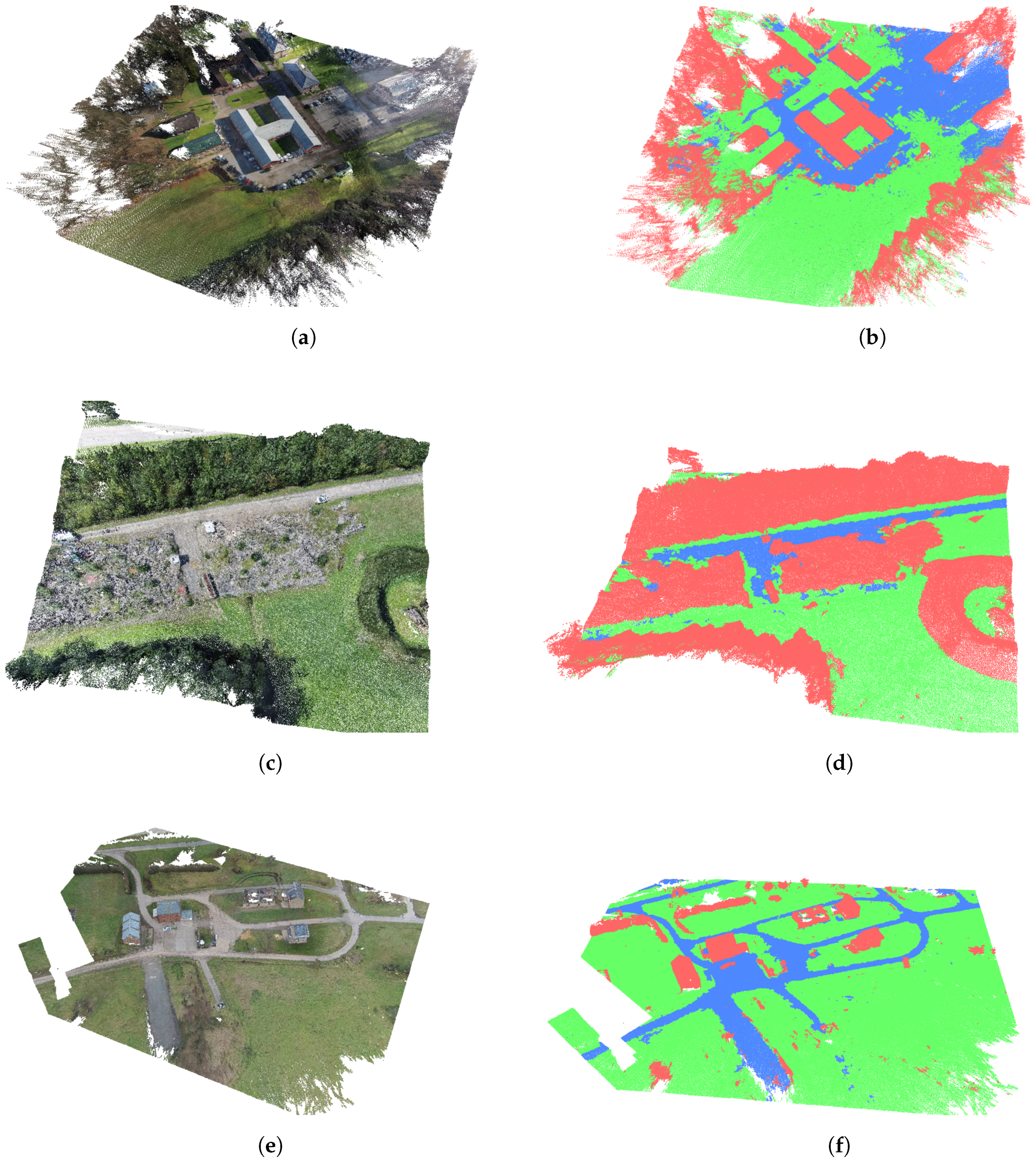
The third module within the proposed framework is an integrated multi-sensor based segmentation. The segmentation process proposed here can be presented as a two-step process: ground-object segmentation and color based region growing segmentation. In the first step, we segment the ground and non-ground points from the point cloud, and the resulting output represents the ground-object segmentation. After that, we perform a color-based segmentation and interpret the scene and assign a label to each 3D area. The idea is to highlight the ground infrastructure and automatically identify landmarks like roads, grass areas, plains, etc. Each of these modules will be described separately in more details in Section 4, Section 5 and Section 6.

4. Data Acquisition and Pre-Processing

In the first step, the data acquisition and pre-processing of the input 3D data is performed. This step is done for both datasets coming from heterogeneous sensors. Terrestrial data acquired by the laser rangefinder, mounted on a ground vehicle, are fused into a consistent terrestrial map. This approach was based on our novel 3D mapping framework named LME-ICP which will be described in the next subsection. The ground matching framework is based on an improved ICP algorithm hierarchically organized into a multi-level processing schema allowing fast and accurate registration of 3D environmental models. A crucial contribution of our framework is the error evaluation process, allowing for overcoming the local minima problem and achieving an optimal registration.
Aerial data acquired from a photogrammetric structure-from-motion approach with digital images collected by an UAV are combined in a parallel and separated processing step, generating a 3D environmental model. This step will be described in Section 4.2. After the two global maps are reconstructed, data handling and preparation of the input 3D scans are performed. This process includes noise reduction through filtering and downsampling for both datasets. This two-step process is described in Section 4.1.1 and Section 4.3 and includes the Voxe-subsampling and FCSOR subprocesses. The data preparation step is necessary in order to filter out noisy measurements and to get more unified dense datasets, thereby saving computational and memory resources in further processing steps.

4.1. Registered UGV Point Cloud Using an LME-ICP Method

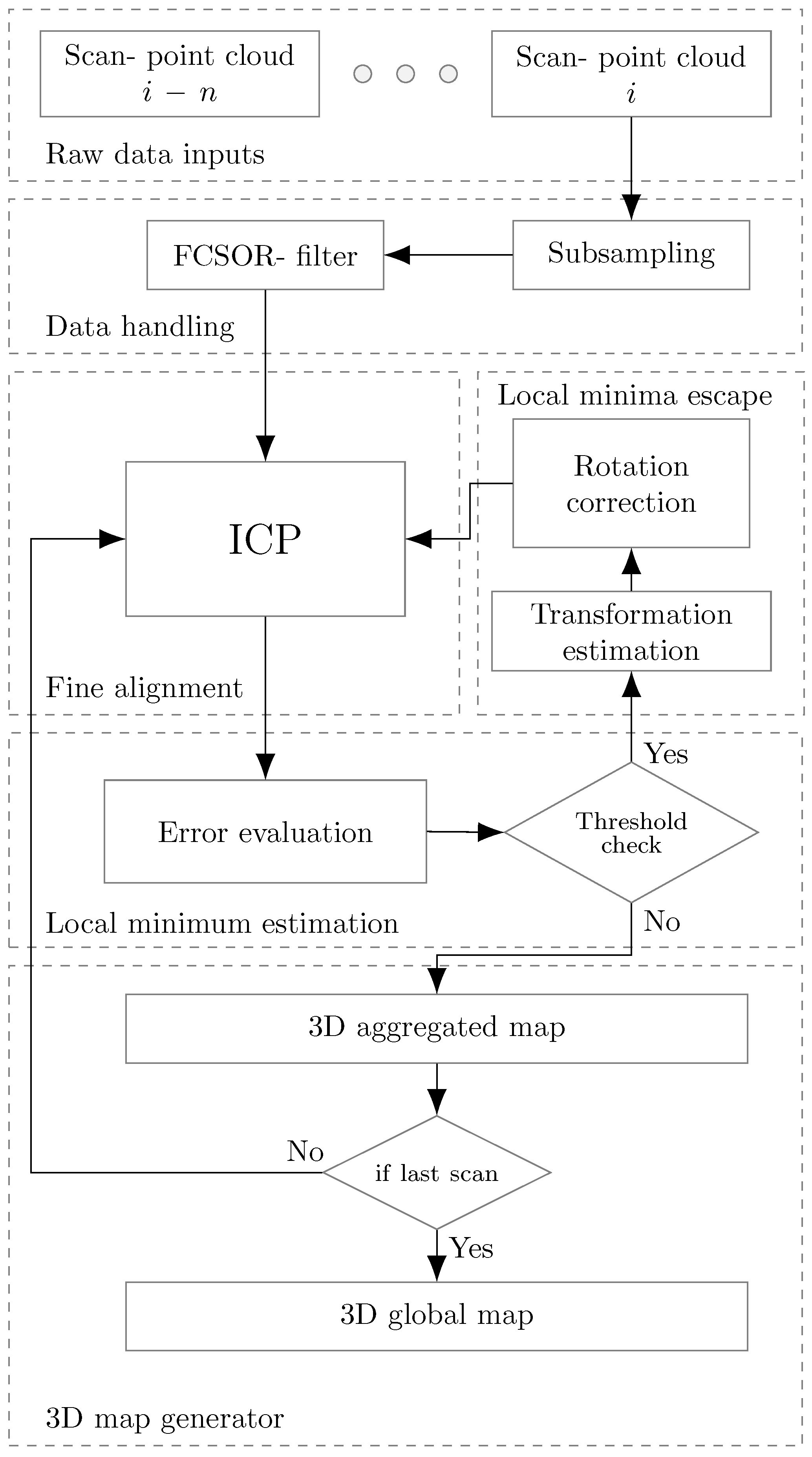
This section describes a novel 3D model registration framework based on our proposed LME-ICP method. To explain the methodology, the framework is elaborated here, showing the pipeline of the algorithm for each of the processing steps, as illustrated in Figure 2. The 3D model registration schema introduces the following four-step process:
  • Data handling and preparation.
  • ICP fine alignment.
  • Local minima estimation.
  • Local minima escape.

4.1.1. Data Handling and Preparation

The data handling and preparation module includes noise reduction through filtering and downsampling for input datasets (point clouds). The 3D point cloud is taken from laser scanner mounted on the UGV platform. This module is necessary to filter out noisy measurements and to get more unified dense datasets, thereby saving computational and memory resources in further processing steps. The output of this framework is the filtered point cloud. It is also input to the post-processing module or 3D modelling process. In this subsection, only voxel-subsampling part is explained, while the FCSOR subprocess will be described in Section 4.3.
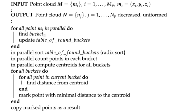
The purpose of the downsampling data is to obtain a highly uniform point density between different point clouds, which represent inputs to the proposed framework. This is required because the scanning technique used for the terrestrial datasets tends to gather clouds whose density changes with range measurement. The solution is based on the voxelized grid decomposition [36]. In our paper, the 3D space of the input point cloud is decomposed into a set of voxels using a constant size of the voxel. After the decomposition step, in each voxel, all points present will be approximated with their centroid. The output of 3D voxel-subsampling algorithm is the uniformed point cloud with decreased number of points. This approach is a bit slower than approximating them with the closest point to the center of the voxel, but it represents the underlying 3D model more accurately. By changing the size of the voxels, different densities of the input data can be achieved.
Algorithm 1 represents the pseudo code of the voxel-subsampling procedure [9].
Algorithm 1: 3D Voxel-subsampling algorithm
Remotesensing 12 01608 i001

4.1.2. ICP Fine Alignment

The ICP approach is one of the most popular registration methods for unorganized 3D data sets [37]. The algorithm is based on an iterative gradient descent method which estimates the optimal transformation between two adjacent 3D scans using a Euclidean distance error between their overlapping areas. The Euclidian distance d between two 3D points p 1 = x 1 , y 1 , z 1 and p 2 = x 2 , y 2 , z 2 can be represented as:
d ( p 1 , p 2 ) = ( x 1 x 2 ) 2 + ( y 1 y 2 ) 2 + ( z 1 z 2 ) 2 1 2
In order to find correspondences between the nearest point pairs in two adjacent 3D scans, it would be impossible to presume that every point in one scan has a known correspondence in the second scan. Therefore, it becomes crucial to design techniques that can robustly estimate good correspondence [17]. The ICP algorithm can be presented with a two step approach [38]:
  • In the first step, it is necessary to compute the correspondences between the two data scans (Nearest Neighbor Search).
  • The second step computes a transformation which minimizes distance between the corresponding points.
Iteratively repeating the previous described two steps will typically result in convergence to the desired transformation, minimizing an alignment error.
More formally, the standard ICP algorithm can be defined as follows [13]. Let two 3D data scans M m o d e l = m i , i = 1 , , M p and P s o u r c e = p j , j = 1 , , N p , where m i , p j R 3 are point coordinates, be the model dataset and source dataset with M p and N p points, respectively. Furthermore, the model dataset M m o d e l represents a set of previously scanned points which is kept fixed and it is called the reference or target. The other dataset P s o u r c e is a dataset of new points from the current scan called the s o u r c e . The source dataset is transformed to best match the reference dataset. If M p > N p , the ICP algorithm should find the sub-point sets M s u b M m o d e l that are most similar to the reference model P s o u r c e . The goal is to estimate the rigid motion with rotation R S O ( 3 ) and translation t R 3 based on a minimum of the error function E. The error function E can be expressed as:
E = f R , t , M m o d e l , P s o u r c e
where R is the rotation component and t the translation component of the transformation matrix presented in Equation (4). The error function E can be rewritten as:
E ( R , t ) = i = 1 M p j = 1 N p e i ( R , t ) 2 = i = 1 M p j = 1 N p w i j ( R p j + t ) m i 2
where w i j is assigned to one if the i-th point of M m o d e l correspond to the j-th point in P s o u r c e in terms of minimum distance, otherwise w i j = 0 .
Given initial transformation R and t can be represented with the transformation matrix
T = R t 0 3 1 s . t . R T R = I 3 , det ( R ) = 1
where I 3 is ( 3 × 3 ) unit matrix and 0 3 is ( 1 × 3 ) null vector. Combining Equations (3) and (4) gives the following minimization criteria:
argmin i M p j N p T · p j m i 2
The ICP algorithm iteratively solves the above minimization (5) by alternating between estimating the transformation (4), and finding the closest-point matches p j P s o u r c e for each m i M m o d e l . Due to the iterative nature of ICP algorithm, it can only guarantee the convergence to a local minimum.
Instead of computing the correspondences between the two data scans for all pairs searched in step 1, usually a robust technique could be exploited to discard certain number of pairs by analyzing the statistics of the distances. In order to implement this, a maximum matching threshold d m a x is set to decide whether to accept a pair or not. Choosing the parameter d m a x is not a trivial task, because it represents a direct trade-off between the convergence and accuracy. Additional information which should be taken into account while defining the d m a x is the initial alignment of the data scans. Setting the d m a x to a lower value can lead to a slow convergence and poor alignments of the data scans. Similar to that, setting the d m a x to a higher value may result in the local minima situation. For example, the initial value of d m a x can be set as two times the average distance between consecutive data scans. The pseudocode of the ICP registration process is given in [17].

4.1.3. Local Minima Estimation

As we mentioned earlier, it is not possible to guarantee the avoidance of local minima using the ICP algorithm. Additional drawbacks of the ICP approach are a small convergence domain and the requirement for a high number of iteration steps until convergence is reached. If the ICP algorithm gets trapped into a local minimum, this leads to erroneous estimations which can be far away from a global optimal solution. Most usual cases where the ICP algorithm fails are poor initial alignment of the data scans and additional noise coming from the unstructured outdoor environments. A possible approach for solving the local minima in such a situation would be providing a good initial estimation (e.g., via the odometry of the robot) of the transformation. However, it is not an easy task to guarantee that the initial estimation is good, especially when dealing with harsh environments. Because of that, our proposed 3D mapping framework doesn’t rely on any prior known pose estimation information (like odometry, GPS, IMU). In order to overcome situations where the estimation transformation of the 3D registration method is far from a global optimal solution, we have introduced an error evaluation mechanism to perceive the local minimum situation. Using this mechanism, we define a cost function which in our case represents the mean sum of the squared Euclidean distances between corresponding points of the source P s o u r c e = p i , and the reference M m o d e l = m i , datasets, where i = 1 , , N p .
The mean square error e function is defined as:
e = i = 1 N r m i p i 2 N r
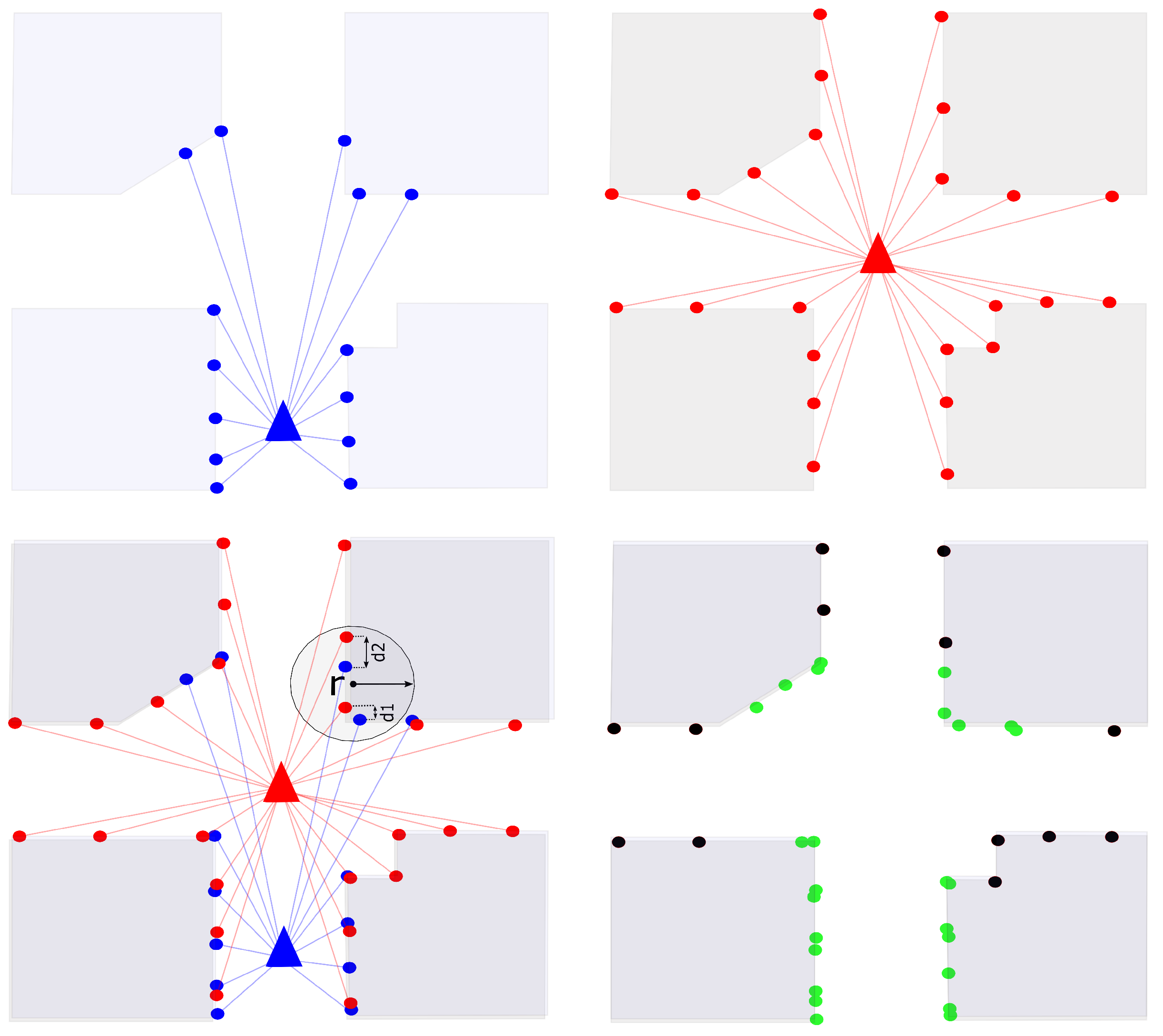
where m i and p i represent the nearest corresponding points between the reference and source dataset, respectively. The corresponding pair points are found by utilizing the K - d tree nearest neighbor search algorithm [17]. Using the distance measure between the corresponding pair points ( m i , p i ) , we can calculate the mean squared error between the scans. Nevertheless, this measure does not accurately represent the error. Each new scan will incrementally increase the global map by adding new environmental information. Some of the new points will not have corresponding overlapping points in the global map and they introduce a large distance error. In order to get a better error estimation, we calculate the pair of corresponding points ( m i , p i ) only in an overlapping area which is defined within a certain radius r.
An example of such situation is shown in Figure 3. Two successive scans are presented with the blue and red point clouds. The overlapping area contains a subsite of N r points between the two scans. In Figure 3, the overlapping area is represented by the green colored points, with a number of N r = 24 points in total. In this case, the overlap radius is taken as a fixed value of r between two points and the error estimation is computed. As already mentioned, defining a radius is necessary in order to avoid error accumulation of points which represent new data of the global map.
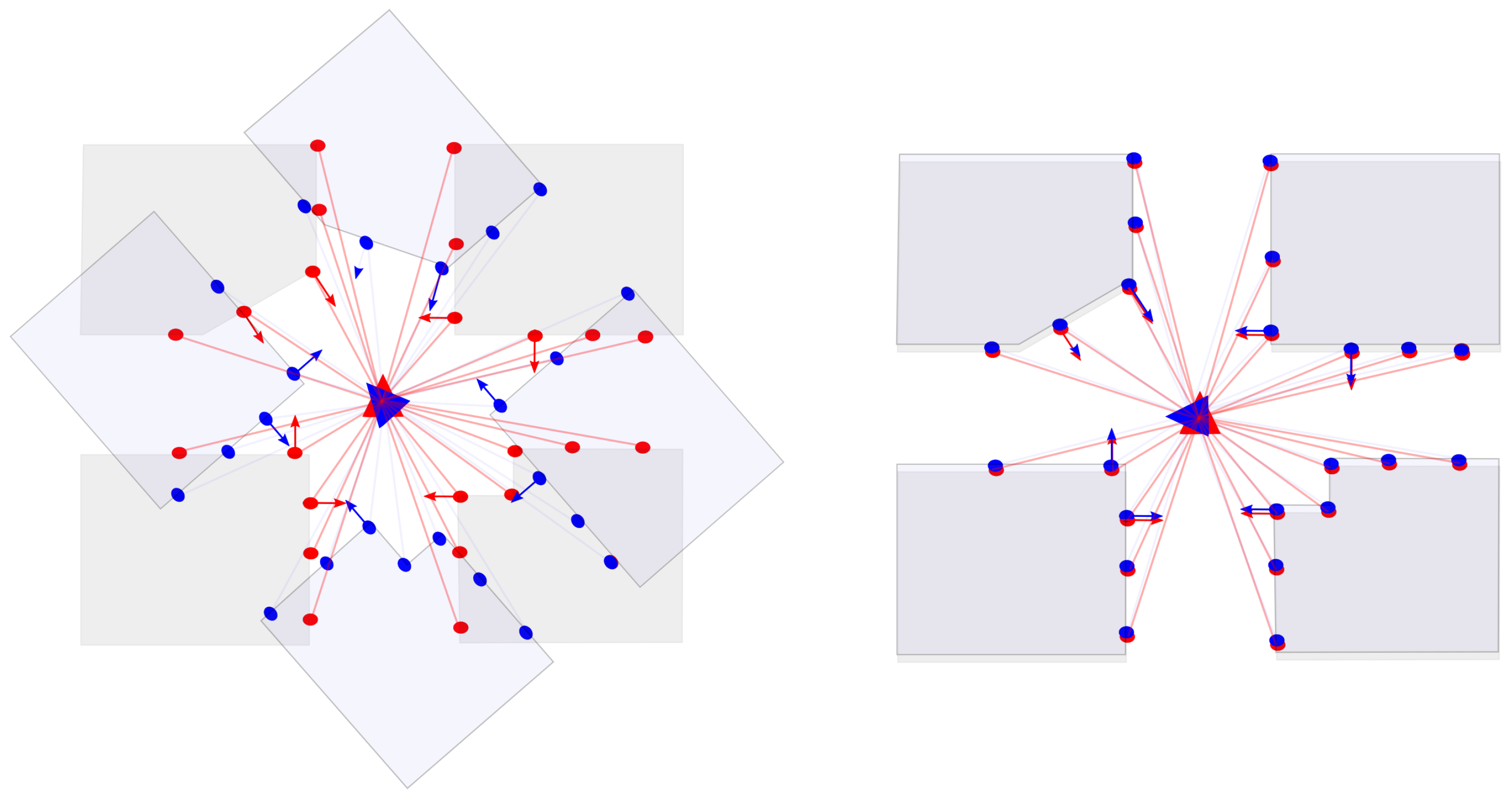
By tracking the error, we can determine if the matching has achieved an accurate registration result or if it has been trapped into a local minimum. Figure 4 shows a situation where the system has detected a local minimum situation. In this figure, we can see a sudden change in the angle of rotation of the position of the scan ( 90 degrees ) which is indicated with the blue scan. In this case, the error has significantly increased and the system is trapped into the local minima as shown in the right part of Figure 4. Evaluating the error, we can usually anticipate that a higher value of the error means that the registration processes has reached a local minimum situation, while a lower value indicates that the registration is successful. However, due to sensor noise, a perfect registration is usually not possible to obtain. Therefore, we need to define a threshold value thError in order evaluate the computed error. If the evaluated error is below a given threshold (which is empirically evaluated using scan evaluation and is usually between 0.5 and 0.7 ), the alignment is good and the new scan can be merged into the global map. If not, the local minima avoidance mechanism will be activated (described in the next subsection).

4.1.4. Local Minima Escape

If the new scan was trapped in a local minimum as shown in Figure 4, a new transformation is computed which is going to move the scan out of the local minimum situation. First, we find all the overlapping points between the global map and the new scan by utilizing the nearest neighbor search [39]. In the second step, the surface normals [40] are computed on the new scan point cloud and overlapping points from the global map as shown in Figure 5. This gives an additional robustness to the transformation as we take in consideration the type of surfaces. For example, points from a wall will be matched only to other points in a wall and so on. The surface normals are directly estimated from the point cloud dataset. The general idea of estimating the normal to a point on the surface is approximated by the normal estimation of a tangent plane to the surface. In general, this becomes a least-square plane fitting estimation problem. This computation can be done by calculating the covariance matrices of the points and then extracting the eigenvalues and eigenvectors. By analyzing the eigenvalues and eigenvectors, we can define the surface normals of a point. Pseudocode of the implemented surface normal estimation is presented in Algorithm 2.
Algorithm 2: Pseudocode representation of the surface normals estimation process
Remotesensing 12 01608 i002
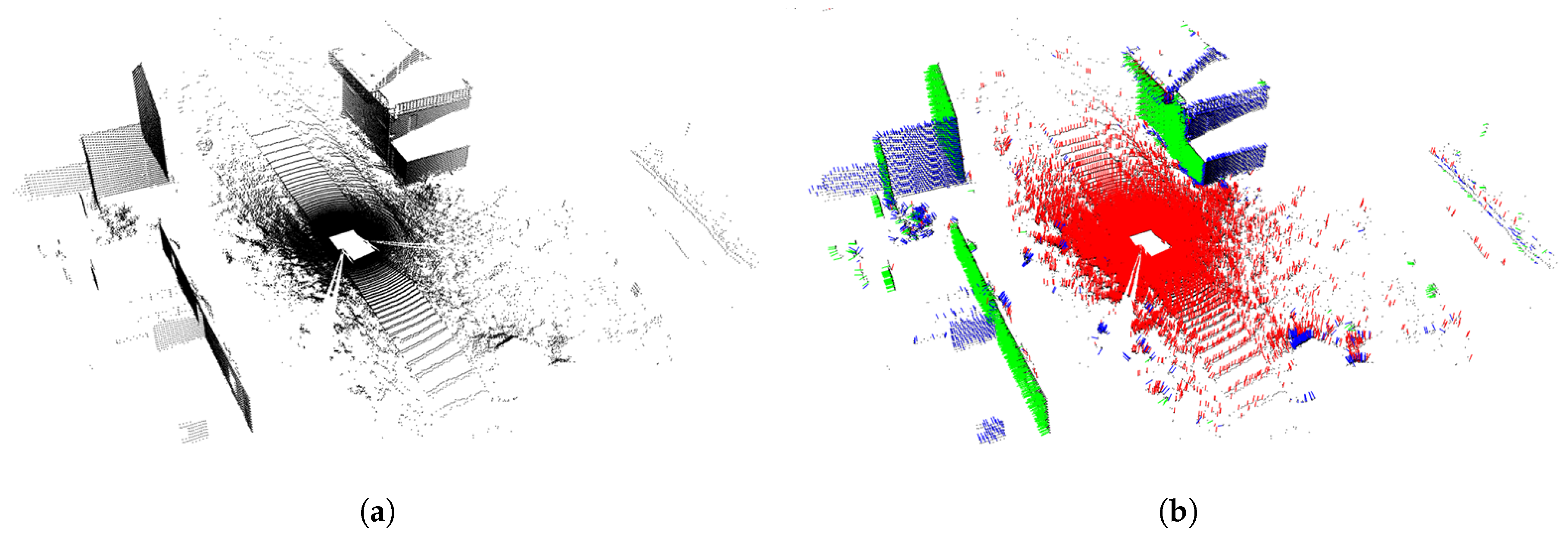
The results of the previously described process of surface normal analysis are shown in Figure 6. The right side of the figure represents the raw data scan (around 137,115 points). The left side shows the developed surface normal estimation method that performs normal vector computation (in parallel) for each query point. The orientation of the normal vectors is shown with different colors—in that way, vectors ( x , y , z ) are represented by the blue color (around 9805 points), green color (around 14,849 points), and red color (around 112,461 points), respectively. After the surface normal estimation, we extract pairs of points from the new scan and overlapping points from the map that have similar normals. After the pairs of points with similar normals have been extracted from the new scan and global map, we calculate a rigid transformation between the pairs. With this transformation, we are able to bring the new scan closer to the global map and avoid the local minima. An additional step has been added to improve the transformation efficiency. Because most of the matched pairs come from around the center of the new scan, the new transformation will be close to the local minima. Therefore, we avoid using these points all together. As a result, the new transformation places the new scan further away from the local minima. Algorithm 3 shows the local minima escape pseudocode.
Algorithm 3: Pseudocode representation of the Local minima escape process
Remotesensing 12 01608 i003
Our proposed LME-ICP was compared with three concurrent methods: Standard ICP, Generalized ICP, Nonlinear ICP in [41]. For the first evaluation step, we have analyzed the convergence of our proposed mapping framework and the three other ICP methods for a scan-byscan registration approach using as an input two random successive scans. After the scan-by-scan evaluation, a global map registration analysis was performed. The mentioned three ICP-based methods generate inconsistent and poor global maps due to a lack of the local minima escape. On the contrary, the proposed LME-ICP method produces a comprehensive map fulfilling the necessary requirements to accurately match all the scans. Producing these good results was directly linked to the problem of the local minima escape which was the main advantage of the LME-ICP method. Therefore, the G-ICP and NL-ICP methods spent much more time in processing of data for map reconstruction from the scans than the ICP and the proposed LME-ICP methods. The ICP method required less time in comparison to our method, but it has no ability to generate a consistent 3D global map.

4.2. Registered UAV Point Cloud Using the SfM Method

The Structure from Motion (SfM) is the process of reconstructing (estimating) the 3D spatial structure of an imaged scene from a set of 2D images [42,43]. It allows that the coordinates of 3D points corresponding to the matched image feature points and estimating camera motion (poses and orientation) as well as the intrinsic and extrinsic parameters for the camera to be computed simultaneously using only corresponding points in each view [44]. The SfM has been one of the most popular image-based 3D modeling algorithms rooted in the computer vision domain. It is widely applicable in many areas including augmented and virtual reality, autonomous navigation and guidance, motion capture, hand-eye calibration, image and video processing, image-based 3D modeling, remote sensing and aerial photogrammetry, segmentation and recognition, and military applications [45]. Therefore, the SfM represents a fast, inexpensive and highly automated method, able to produce 3D information from unstructured aerial images.
The 3D scene reconstruction of SfM approach contains two main steps: camera pose estimation and 3D point cloud reconstruction (point cloud extraction). Key-points (points of interest) in multiple images are matched using Random Sample Consensus (RANSAC) algorithm [46]. In the other words, RANSAC is employed to calculate the homography between two images by using two sets of SIFT points and to compute the transformation which minimizes the re-projection error. In addition, the one of advantages of the RANSAC algorithm is its capability to eliminate any outliers which may still be contained within matched points.
After detecting the point correspondences between different images (feature matching) through the comparison of two sets of feature descriptors, we estimate the fundamental matrix and from that obtain the essential matrix. These matrices completely describe the geometric relationship between corresponding points of multiple images. Since we used uncalibrated camera, computation of fundamental matrix is required. It is estimated using the eight-point algorithm [47]. This algorithm uses eight correspondences in two views and compute parameters of fundamental matrix with them using the least-square method. When the essential matrix is obtained, we know where each camera is positioned in space, and where it is looking. In order to determine points in the 3D world frame, the current projection matrix is computed from decomposition of the essential matrix (SVD). Based on the obtained projection matrix, 3D points are determined by triangulation.
When the triangulation is done and the 3D model is reconstructed, the bundle adjustment module is used to optimize and refine the 3D structure of the reconstructed scene and the estimated camera poses. Since we are working with uncalibrated cameras, the bundle adjustment algorithm optimizes over the camera intrinsics as well. The final outputs of processed UAV images by applying the SfM approach are a dense point cloud, digital surface, and terrain models as well as high-accuracy digital orthophotos. In the case of generating 3D UAV point cloud data, we have used existing software solution (Agisoft PhotoScan (St. Petersburg, Russia)) based on a structure from motion approach, allowing 3D reconstruction based on 2D images.

4.3. Fast Cluster Statistical Outlier Removal

Due to the massive amount of data generated by the 3D acquisition devices, there will be several points which do not respect the homogeneity of the dense surrounding neighbors. Such points do not provide a good representation of the underlying sampled environment. Thus, points which are rather isolated are likely to be outliers. Removing these noisy measurements, e.g., outliers, from a point cloud dataset leads to an overall faster computation, due to the reduced error. Therefore, in this work, we propose an extension on the statistical outliers removal (SOR) method presented in [17]. The motivation for extending the previously mentioned method is naturally related with the heterogeneity of large datasets (several million points) we are dealing with. The datasets coming from airborne and terrestrial point clouds, acquired by different type of sensor systems, imposes uneven point density and measurement errors. Another motivation for the extension of the classical statistical outliers’ removal method is the high computational time necessary to process such type of datasets with the traditional SOR method.
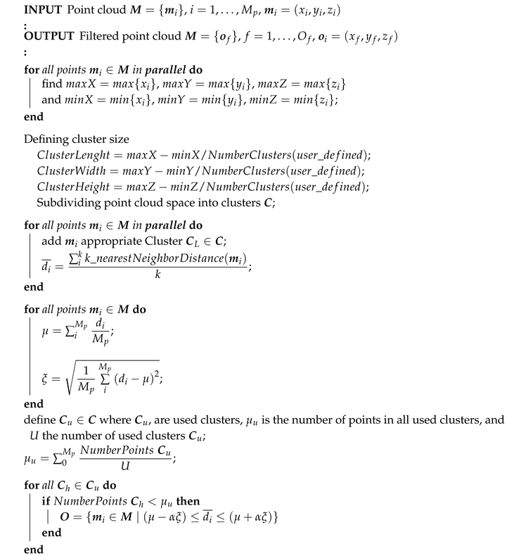
Based on the previous mentioned limitations, our proposed solution relies on a clusterization and dimensional reduction method of the 3D space that lowers the computational complexity. This section proposes an original extension of the SOR method, which we are calling Fast Cluster Statistical Outlier Removal (FCSOR), and the pseudocode is given in Algorithm 4.
Algorithm 4: 3D data filtering—FCSOR method
Remotesensing 12 01608 i004
The implementation allows for performing computations partially in parallel and in that way we reduce the computational time. The 3D space of the input point cloud is divided into equal number of clusters C. For each point p i P where P is the input dataset, the average squared Euclidean distance d i to its k-nearest neighbors is first computed and each p i is added to the appropriated cluster c L C . The dimensional reduction of the 3D space is done by firstly computing the mean number of points μ u from all clusters c L . If the number of points in a particular cluster is higher than the average μ u , that cluster is rejected from the further computation. By reducing the number of clusters, we can greatly speed up the computation as we have less points to search. The resulting filtered point cloud P * is estimated from the remaining clusters as in the SOR method.
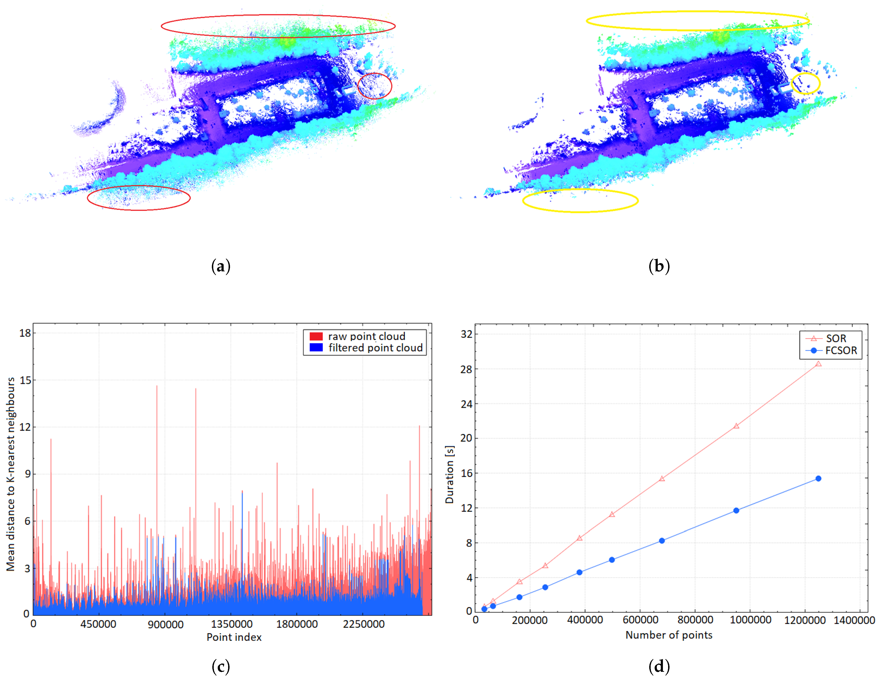
The resulting procedure of the outliers (noises) removal using the FCSOR method is shown in Figure 7. A raw point cloud dataset with noisy measurements, e.g., outliers, is shown in Figure 7a, where identified outliers are marked with red circles. The resulting 3D point cloud obtained by using the proposed FCSOR filter is presented in Figure 7b, indicating the effect of removing the outliers (with number of points left: 8,891,294 out of 9,109,169, i.e., 97.60 % ). For the purpose of these experiments, the value of α (threshold factor) was set to 2 and the number of k-neighbors to 25. The graph presented in Figure 7c shows the relation between the filtered and non-filtered point cloud datasets. It can be noted immediately from the figure that the mean distance to the k-nearest neighbors is drastically reduced in the filtered version.
The execution time comparison between the classical SOR and our improved FCSOR method is shown in Figure 7d. The figure clearly shows that the proposed FCSOR method is about twice faster than the traditional SOR method and thereby proposes a viable alternative for the traditional method. When handling larger datasets, the FCSOR is more efficient in terms of time complexity, since SOR requires O ( n 2 ) running time per number of input points, whereas the FCSOR is O ( n ) .

5. Semi-Automated Heterogeneous UGV-UAV 3D Registration

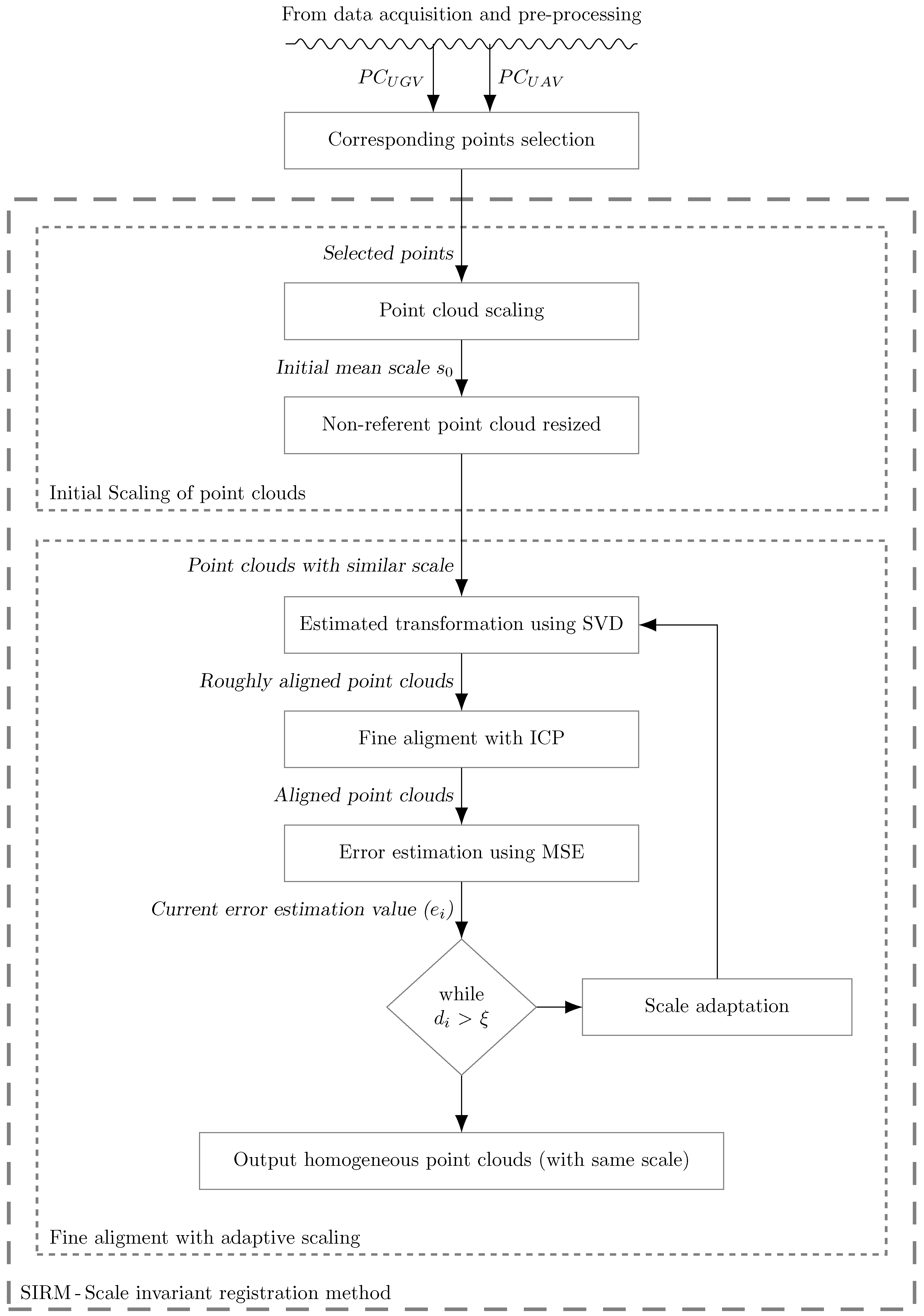
In order to overcome limitations of dealing with 3D data sets from different sensors and different perspectives of the environment, we propose a semi-automated and robust 3D registration approach based on the SIRM method. The proposed semi-automated 3D registration method is shown in Figure 8.
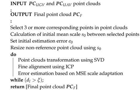
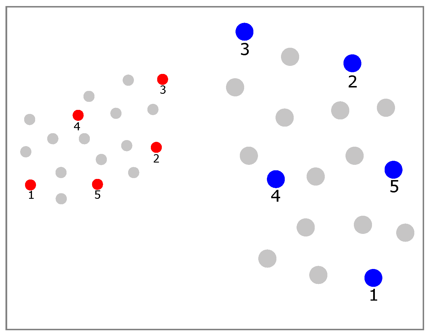
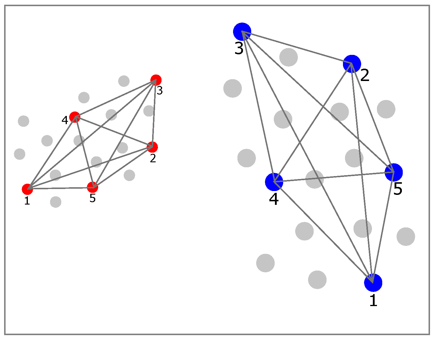
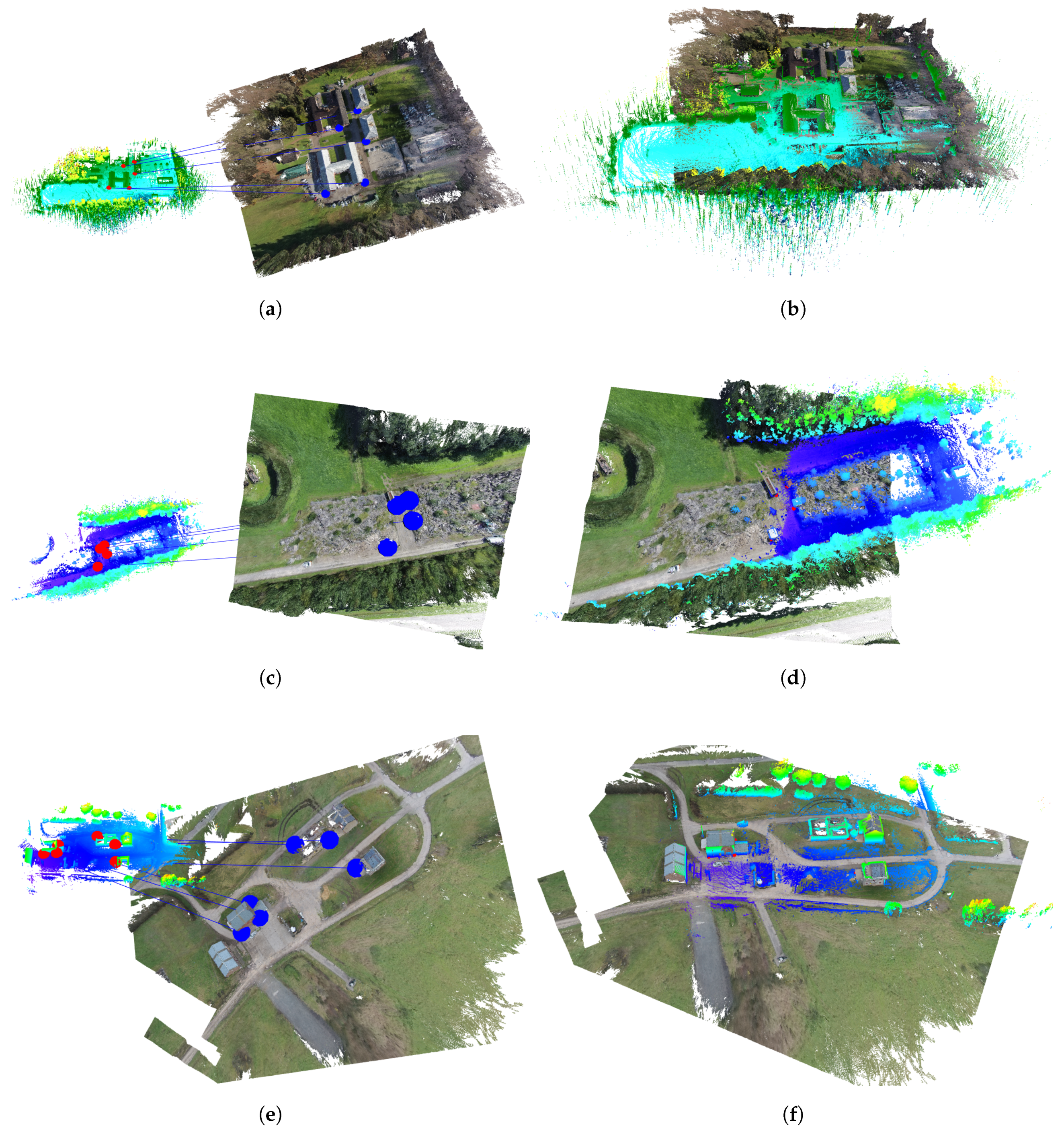
The SIRM method is primarily used to align the UAV and UGV point cloud datasets in order to obtain an accurate registration. Its main parts are initial scaling of point clouds and fine alignment with adaptive scaling. The SIRM method is used to solve the problems of displacement, orientation, and scale difference between the point clouds. The proposed approach is based on manually marking at least three corresponding point pairs in both point clouds. The transformation between the point clouds is computed, and the SIRM method is performed. Therefore, the SIRM is capable of coping with an arbitrary scale difference between the point clouds, without any information about their initial position and orientation. Before applying the SIRM, we manually select K p s of corresponding points within the two heterogeneous point clouds, acquired by the UGV and UAV. Let R = { r k } and B = { b k } , k = 1 , , K p be sets of corresponding points in the UGV and the UAV point cloud, respectively, where K p is the number of points in each point cloud and K p s 3 . The set R M m o d e l and B P s o u r c e , where M m o d e l = { m i } , i = 1 , , M p and P s o u r c e = { p j } , j = 1 , , N p are respectively the UGV and UAV point clouds. The selection of the corresponding points is based on some recognized landmarks, e.g., edge of a house, roof, etc. It is very important to note that the proposed SIRM method overcomes the error between the selection of the corresponding points of heterogeneous point clouds in a range of few meters. This is shown in Figure 9, where K p s = 5 preselected red points representing the corresponding points within the UGV point cloud. The same number of points are selected within the UAV point cloud, which are blue in color. It is obvious that the UAV point cloud has a larger scale and a translational displacement.

5.1. Initial Scaling of Point Clouds

After selecting corresponding points, the next step is to determine the initial scale. This step is important because we want to achieve homogeneity of the two point clouds by firstly getting them to a similar scale. The initial scale is computed using the mean distances of all possible connections between the selected points as shown in Figure 10.
We have introduced the following expression for the initial scale:
s 0 = i = 1 K p s j = i + 1 K p s r i r j b i b j N p s
where r i r j and b i b j are the Euclidean distances between two corresponding points in the same point cloud and N p s is number of all possible connections of the preselected points, N p s = k ( k 1 ) 2 .
Once the first initial scale s 0 is computed, we apply its value to resize the UAV (blue) point cloud to be close to the similar scale as the UGV (red) point cloud. In our case, we rescale the UAV point cloud and use the UGV point cloud as a reference model. Then, we obtain two point clouds with a relative similar scale which allows us to proceed to the second module of the proposed 3D registration approach, the fine alignment with adaptive scaling.

5.2. Fine Alignment and Adaptive Scaling

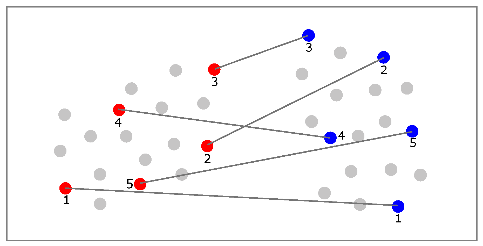
After obtaining the similar scale of the two heterogeneous point clouds, a transformation between them is calculated using the singular value decomposition (SVD) [48]. An initial transformation has registered two point clouds relatively close to each other. However, this kind of registration is dependent on the precision of the pre-selected corresponding points and the initial scale computation. Therefore, a good selection of the corresponding points in both point clouds can have a major impact on the scale computation and the final registration results. In order to minimize the error, introduced by the user while selecting the corresponding points, a fine alignment based on an ICP method [37] is exploited. In every iteration, the ICP will improve the point clouds alignment. Further improvement is obtained by fine-tuning the initial scale computation and transformation registration. For this purpose, the proposed SIRM involves a mechanism for adaptive scale tuning of the mean scale s. It produces the correcting scale factor s c which is related to the relative difference between two consecutive mean square errors of the two heterogeneous point clouds. The computed value of s c is then added to the previous mean scale s. After each iteration, the s c is adjusted and a new transformation between the two points clouds is calculated. The performed transformation is illustrated with black lines in Figure 11.
In order to evaluate the registration quality, the displacement between the two point clouds in every iteration is computed using a mean squared error (MSE). It is based on the Euclidean distance between the nearest neighboring points from the M m o d e l and P s o u r c e point cloud. The mean square error e is expressed by the following equation:
e = i = 1 N m i p i 2 N
In addition, only point pairs with distances shorter than a predefined radius r are taken into account. This radius based error computation is introduced because a significant error is generated by points from the target point cloud which are not captured in the source point cloud, i.e., only the points in the overlapping area with radius r are considered. In each iteration of the adaptive scaling and fine alignment step, we estimated the current error value e l in accordance with Equation (8). Then, the previous error value e l 1 is subtracted from the current obtained error value e l , where the initial error is set to a large value. The difference between them is given by:
d l = e l e l 1
The updated mean scale s is computed in each iteration by using the following relation:
s l = s l 1 + s c l
where s c l is correcting scale factor and l is the number of the current iteration. This correcting factor is updated in each iteration based on d l and error ratio e l and e l 1 :
s c l = d l · ( e l / e l 1 )
This adaptive mechanism continues to operate until the error difference d l becomes larger than the predefined threshold value ξ . The s c l factor indicates the quality of point clouds alignment with respect to ones in the previous iteration. The smaller values of s c l mean the better quality of point clouds alignment. This performance index has a smaller value in the case of a simultaneous smaller value of the current e l and larger value of d l .
The proposed semi-automated 3D registration obtains relatively accurate initial point clouds alignment when the selected points are corresponding in both point clouds. In this case, the scale adaptive mechanism will very quickly provide accurate point clouds matching with a small mean square error in few iterations. The main power of the SIRM lies in the fast error convergence in heterogeneous point clouds alignment when the selected points from both point clouds are non-corresponding. The initial error alignment is larger than in the first case, but the scale adaptive mechanism will reduce the error in several iterations and produce a very precise final point cloud. It will be concluded that the scale adaptive mechanism ensures fast convergence of the alignment error and provides very accurate final point cloud. The pseudocode of the proposed semi-automated registration is presented in Algorithm 5.
Algorithm 5: Semi-automated 3D registration method
Remotesensing 12 01608 i005

5.3. Heterogeneous to Homogeneous Color Assignment

Combining heterogeneous data models into homogeneous ones requires the transfer of properties from one data model to the other. In this work, we focus on the combination of heterogeneous datasets acquired by a laser rangefinders (installed on UGVs) and a digital camera (installed on UAVs). The UGV laser rangefinder is only capable of acquiring structural data about the environment and has no color-texture information, whereas the photogrammetric 3D reconstruction approach applied on the UAV data enables the acquisition of structural and color data. In order to obtain a unified homogeneous 3D model, we thus need to transfer the color data from the UAV point cloud to the UGV point cloud. The transfer of the color is important because we have based the proposed segmentation method on the color properties within the resulting point cloud.
The proposed color assignment algorithm is simple and very effective. It requires a good alignment between the two point clouds. The main concept of the algorithm is to transfer the RGB color value from one point cloud to another based on the nearest neighbor search problem. In that case, the average RGB value of the N n nearest neighbors from the UAV point cloud is computed and assigned to the RGB value of a query point u i within the UGV pointcloud. The pseudocode of the proposed color transformation algorithm is shown in Algorithm 6.
Algorithm 6: Pseudocode representation of the point cloud color assignment
Remotesensing 12 01608 i006
After applying the color assignment as presented by Algorithm 6, a homogeneous and integrated point cloud is obtained. This integrated homogeneous point cloud is now ready to be further exploited, as discussed in the following section.

6. Integrated Multi-Sensor Based Segmentation

In this section, we introduce a method for color point-based segmentation of 3D point clouds. The segmentation process of 3D point clouds can be defined as a grouping of points in regions based on similarity criteria (object classification). The group of regions can be generated by using different criteria parameters, such as color, slope, size, etc. [49]. Segmentation is a very important step in processing the point clouds. Indeed, combining the point clouds from the aerial and ground vehicles generates a very dense global map of the environment with many millions of points. In some cases, processing the data on the dense global map itself can be sufficient for doing measurements and volumetric calculations. However, in many cases, more advanced point cloud processing steps, including automatic segmentation, are required in order to process additional information into planes or more complex geometric regions. This step is certainly necessary if it is required to perform scene interpretation and if semantic labels need to be added to each of the 3D point cloud segments such as roads, ground, buildings, trees, etc. The segmentation process proposed here can be seen as a two-step process: ground-object segmentation and color based region growing segmentation.
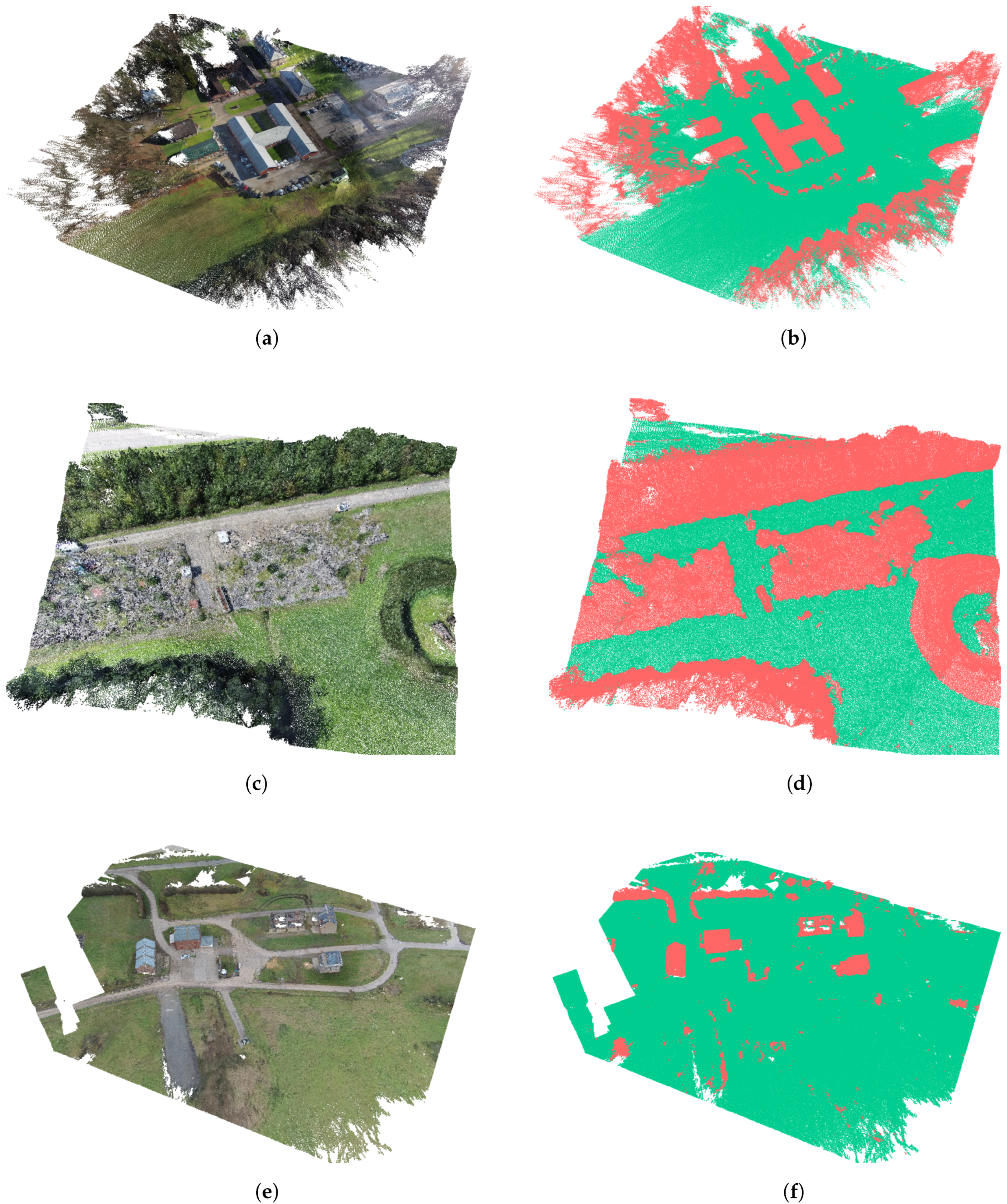
In the first step, we segment the ground and non-ground points from the point cloud, and the resulting output represents the ground-object segmentation. The progressive morphological filtering (PMF) algorithm [50] is able to segment different sized non-ground points such as objects, trees, buildings, etc. and keep only the ground points. This process is done by gradually increasing the window size and elevation difference thresholds. The use of the progressive morphological filtering algorithm is described in Section 6.1. After the progressive morphological filter is applied and the ground and non-ground points are segmented, the ground data can be further used in order to add an additional level of processing. We perform a color-based segmentation and interpret the scene and assign a label to each 3D area. The idea is to highlight the ground infrastructure and automatically identify landmarks like roads, grass areas, plains, etc.

6.1. Ground-Object Segmentation

In the first step of the segmentation, we separate the point cloud between ground and non-ground points. A lot of different ground segmentations methods have been introduced in [51]. Choosing an appropriate segmentation method depends on the type of features which are dominant in the point cloud datasets. One example of a segmentation method is the slope based filtering algorithm proposed in [50]. In that approach, the author is suggesting to use slope differences between nearby points where the segmentation of ground and non-ground points is estimated solely by comparing height differences between a point and its neighbors. A point is segmented as ground point if the highest value of the slopes between that point and its neighbors is smaller than a predefined threshold. The smaller the value of the threshold that is set, the more objects will be segmented as non-ground.
In our case, we decided to use the progressive morphological filter (PMF) [52] and implement it into our proposed the semi-automated 3D registration system. The motivation of choosing the PMF method is that the segmentation process is working well in cases where the point cloud datasets have abrupt changes in the geometric continuity of the scene (e.g., if there is a need to segment buildings and other objects like trees and bridges from the ground points). The progressive morphological filter belongs to the group of slope based segmentation methods, and it depends on the dilation and erosion operations, which are used in mathematical morphology. The dilation and erosion operations are applied in order to increase or decrease the size of the objects. Combinations of these operations lead to opening and closing operations [52]. In order to achieve the segmentation, the PMF works on a gridded surface, which is created from the point cloud. The grid cell sizes correspond to the minimum height value of the point cloud within the grid cell. Then, a morphological opening operation is applied iteratively in order to segment the grid surface. For each segmentation step, only the objects with a size larger than each window size are preserved. This operation is iteratively repeated by gradually increasing the window size and using a difference elevation threshold. With the gradual growth of the window sizes and the elevation difference threshold which also changes accordingly, the points belonging to the ground will be segmented gradually by applying the morphological criteria. The final output of the progressive morphological filter is a point cloud with points segmented into two class sets representing ground and non-ground points. The implementation of the PMF was based on an open source Point Cloud Library (PCL) [36].

6.2. Color Based Region Growing Segmentation

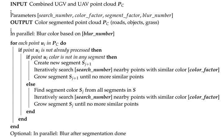
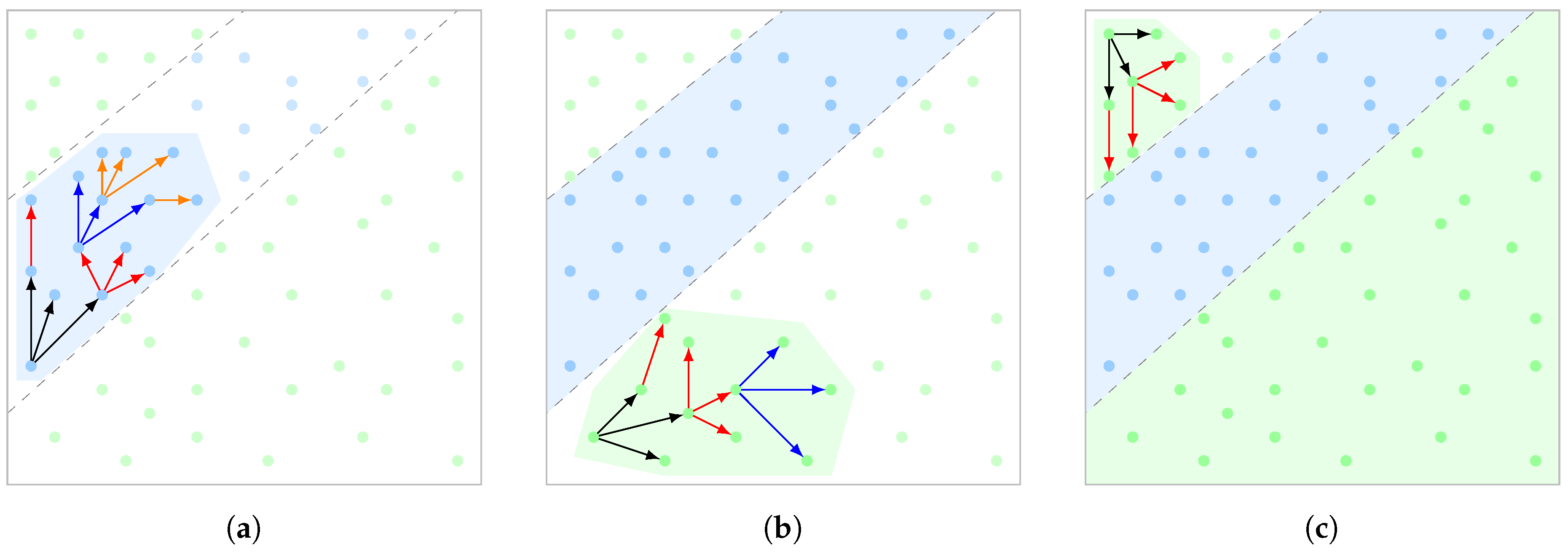
After performing the segmentation between ground and objects from the point cloud, the ground data can be further used to highlight infrastructure. The purpose of doing this is to help the user identify landmarks like roads, plains, etc. Here, we propose a segmentation method based on the color information for each segment. The main concept is to iteratively traverse through the point cloud and assign each point based on its color to an appropriate segment or create a new segment. This is shown in Figure 12a, where the algorithm iteratively checks each point and its neighbors if they are belonging to an already existing segment, denoted with a blue color. The algorithm will grow through the segment until no more similar point colors are detected like shown in Figure 12b. The previous steps will be repeated until no more points are left in the complete point cloud shown in Figure 12c.
The inputs to the algorithms are:
  • search_number is the number for neighboring points used for the region growing.
  • color_factor, which defines the allowed deviation from the initial color for each region.
  • segment_factor, deviation from new points and existing segments.
  • blur_number, used for blurring the image before and after the segmentation.
The blurring of the image is executed in parallel. Furthermore, for each new point located outside of the existing region, the algorithm checks its color similarity with points in the neighborhood for the possible assignment to an existing segment. If this is positive, then we use this segment color and grow the region. If there are no segments with a similar color, then a new segment is created and the region is grown until there are no more similar points in the neighborhood.
The pseudocode of the proposed color based region growing segmentation algorithm is shown in Algorithm 7.
Algorithm 7: Pseudocode representation of the color region growing
Remotesensing 12 01608 i007

7. Experimental Results

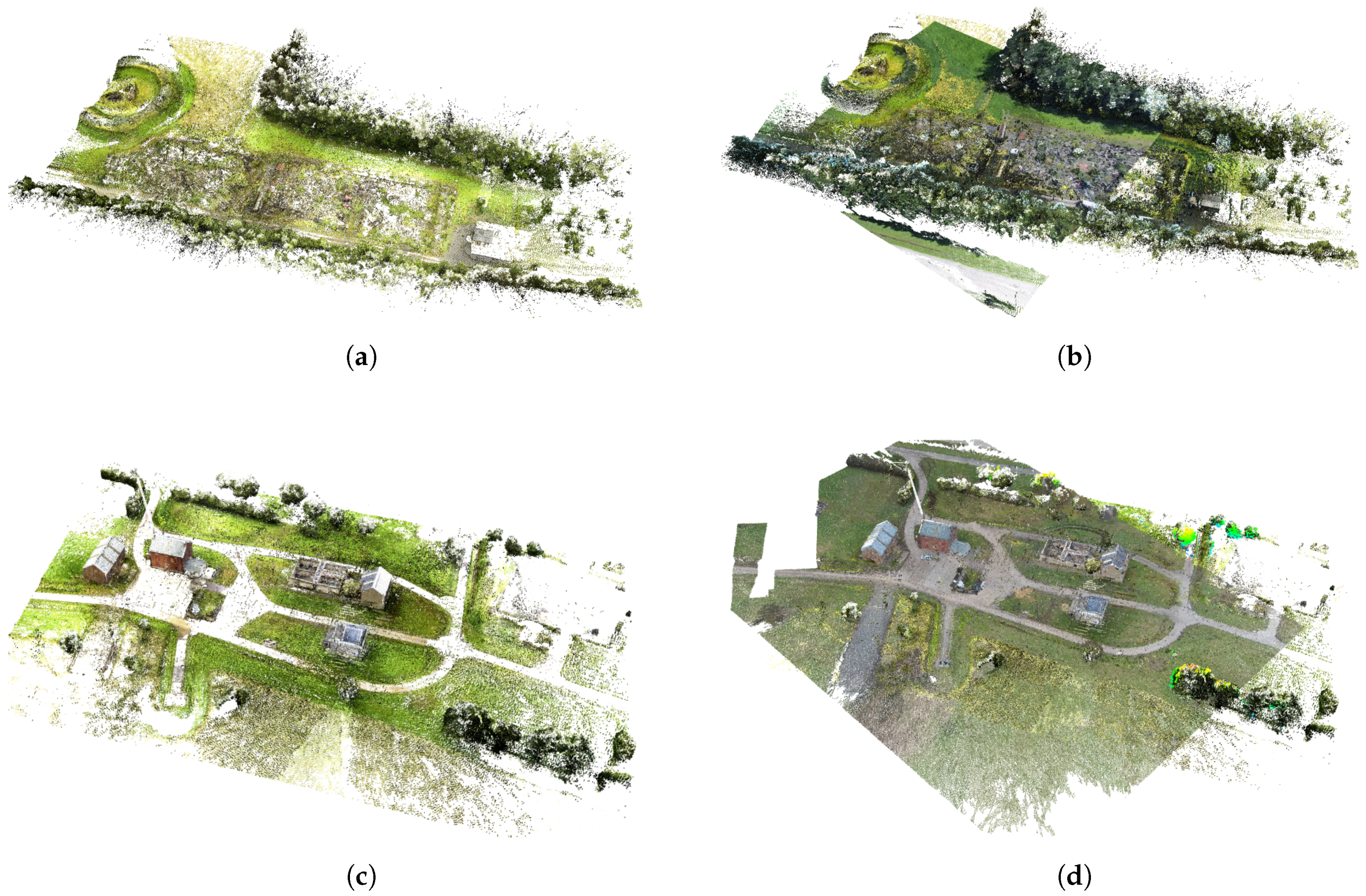
The effectiveness of the proposed framework will be verified in this section for three large scale outdoor environments, entitled Village, Rubble, and Dovo. Dimensions of the mapped environments are significantly large (Rubble and Village: 600 m × 200 m ; Dovo: 300 m × 250 m ). We have performed a qualitative and quantitative evaluation by randomly introducing additional scale, translational, and rotational errors. The performance of the proposed method was assessed by two different experiments considering the difference between the selected corresponding points in the heterogeneous point clouds. In addition, performance analysis is done by using an additional set of parameters: number of selected points, computation time, and required computer resources (CPU load) for the completion of the specified task. Therefore, for the final evaluation, we used an accurate ground truth reference model created by a terrestrial geodetic laser system. We have compared the registered UGV-UAV data with the proposed SIRM method with respect to the ground truth using the least square method (LSM). Furthermore, the experimental validation of the proposed 3D heterogeneous registration and integrated segmentation framework was performed on large-scale datasets representing unstructured outdoor environments, demonstrating the potential and benefits of the proposed semi-automated 3D registration system in real-world environments.

7.1. Experimental Setup

In this section, we will describe the used experimental setup which consists of a UGV robot equipped with a 3D mapping system and UAV platform with a 3D mapping system.

7.1.1. UGV Platform and 3D Mapping System

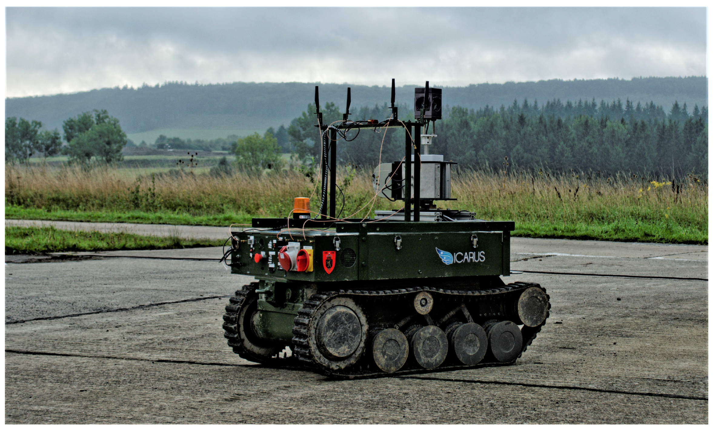
In order to provide required perceptual data input for environmental perception and navigation assistance, a depth sensing system was integrated on the UGV (RMA tEODor UGV) [39]. This exteroceptive 3D mapping system is dedicated to gathering 3D data of the mission environment. The RMA tEODor UGV (Figure 13) has excellent maneuverability over the rough terrains and good off-road performance through its tracked system. During the mapping process the RMA tEODor UGV usually traverses 4–5 m between each scan. The distance between scans is one of the key parameters in the mapping framework because this allows a good overlap between the scans. For each scan of the environment, the laser scanner needs to perform a full revolution which usually takes around 10 sec. It means that the traverse speed of the tEODor UGV is about 0.5 m/s in our experiment. During the experiments, all the 3D environmental data were gathered online on an embedded PC, directly integrated on the RMA tEODor UGV platform (Intel i7-2650 4 Core @2.4 GHz CPU (Santa Clara, CA, United States) with 16 GB of RAM). The software framework was developed using the C++ programming language, and it was based on the Robot Operating System (ROS) [53] and Point Cloud Library (PCL) [36]. In addition, all the data are backed up via the ROS-bag mechanism. The size of the mapped area we worked on during our experiments is approximately 600 m × 200 m. Afterwards, the iterative 3D mapping framework is applied performing point cloud registration, where the latest scan is localized and matched to previous scans increasing the overall 3D map of the environment. The process is repeated until a complete 3D map is constructed.
In order to assess the proposed 3D mapping framework, we have used an accurate geodetic reference model of the scanned area created by a terrestrial geodetic laser system Z+F IMAGER 5010 (Wangen im Allgäu, Germany) and registered with geodetic precision. Due to the high precision and accuracy ( 1 mm ) of the geodetic reference model, we were able to use it as ground truth in order to compare it with the generated model by our 3D mapping framework.

7.1.2. UAV Platform and 3D Mapping System

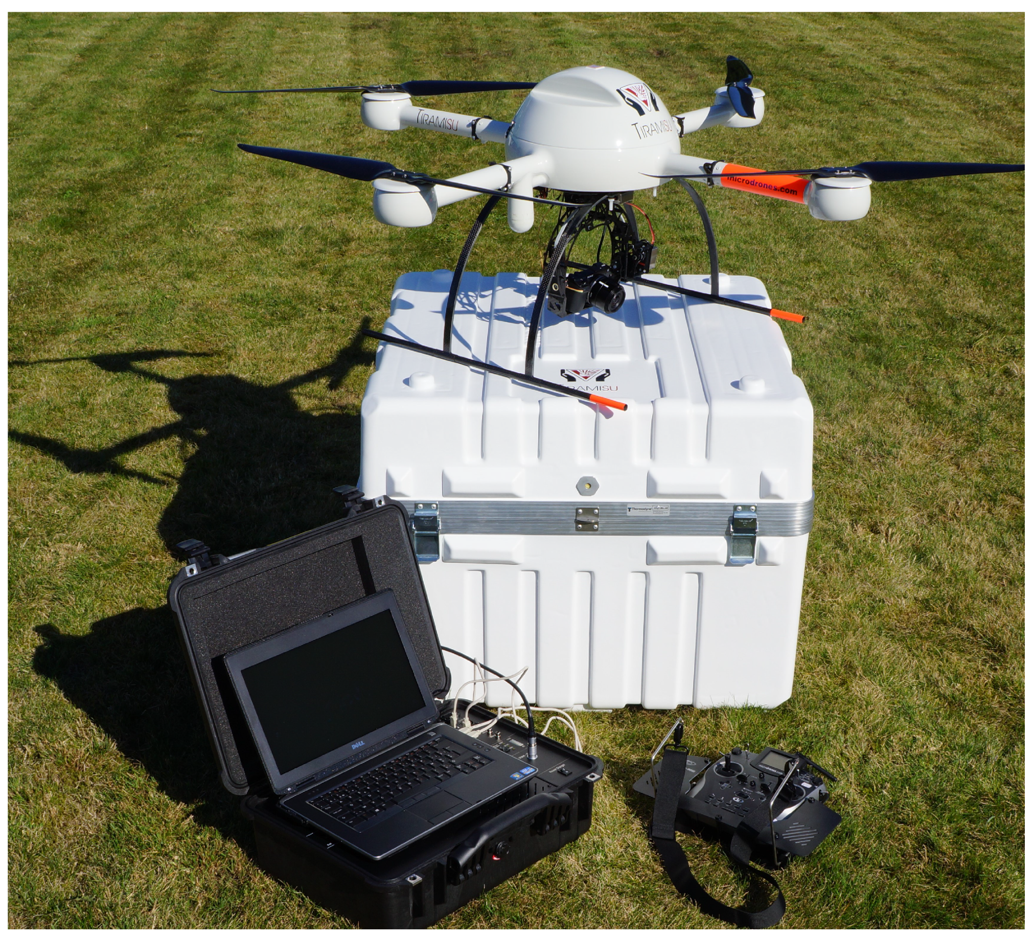
The experimental UAV system used in this work is a small vertical take-off aerial system md4-1000 from Microdrones (Siegen, Germany) (Figure 14). This UAV is a quadrotor-based aerial system, with 1030 mm diameter and complete carbon body with a maximum payload of around 2 kg. The four gearless brushless electric motors are powered by lithium batteries. Depending on the weight of the payload, state of the batteries, environmental, and flight conditions, the UAS can fly for about 35–40 min (the technical specification is claiming more than 70 min). The autopilot is built on a small micro-processor collecting aerodynamics information through a set of tightly coupled sensors (GPS module, 3D-magnetometer, three-axis gyroscope, three-axis accelerometer and a barometric pressure sensor), allowing to fly autonomously waypoint based flights. The UAV system is equipped with a Sony NEX-7 24.3 megapixel digital camera (Minato City, Tokyo, Japan) with an 18mm lens. The camera is mounted below the UAV on a 2-axis gimbal with high precision tilt and roll stabilization (because of the strong and multidirection wind) in real time to provide better images for aero triangulation and mapping.

7.2. Validation Protocol

In this section, we have used the UGV and UAV point clouds produced in Section 4.1 and Section 4.2. Here, we validate how these heterogeneous point clouds are integrated into a homogeneous one, by using the proposed 3D heterogeneous registration and integrated segmentation framework shown in Figure 1. The effectiveness and robustness of the proposed framework will be verified through real-world experiments for three large scale environments: Village, Rubble, and Dovo. It is very important to note that the dimensions of the mapped environments used in these experiments are significantly large (Rubble and Village: approximately about 600 m × 200 m ; Dovo: about 300 m × 250 m ), which additionally validates the effectiveness and robustness of the proposed semi-automated 3D registration system on large-scale environments. Moreover, we have performed a qualitative and quantitative evaluation of our proposed framework by randomly introducing additional scale, translational, and rotational errors. In addition, we used a geodetic high precision and high accuracy ( 1 mm ) reference model as ground truth in order to compare the homogeneous point cloud produced by our framework with the ground truth. Therefore, the computation time and CPU occupancy for the reconstruction of the 3D global map from acquired scans were analyzed.

7.3. Obtained Results with the Proposed Semi-Automated 3D Registration System

In order to evaluate the effectiveness and robustness of our proposed semi-automated registration process of the ground and aerial datasets, comprehensive experiments including ten different scenarios are conducted. In this subsection, only the robustness of the proposed framework is validated, while its accuracy will be verified in Section 7.4 with respect to the ground-truth model. In general, the registration is depending on the precision of the pre-selected corresponding points by the user in the heterogeneous point clouds. However, our proposed 3D registration system has the intention to overcome the dependence of the 3D registration quality based on the selection of the corresponding points between the heterogeneous point clouds. The introduced SIRM method with the scale adaptive mechanism tries to solve that problem.
The performance of the proposed 3D registration system was assessed by two different experiments considering the difference between the selected corresponding points in the heterogeneous point clouds. In the first experimental study, the user has visually selected the good matching points in both point clouds. A good corresponding point represents the paired points from both point clouds which are selected from the set of recognized landmarks, e.g., edge of a house, roof, etc., with satisfactory small displacement between them (usually in a cm range). The second study considers the situation where the user failed in the selection of the corresponding points between the two point clouds in a range of several meters, which is a significant translation error for the scale and registration procedures.
Each of the considered scenarios in these experimental studies has been evaluated on the Dovo dataset, introducing a randomly generated scale and transformation displacement error on the non-referent point cloud, in our case the UAV point cloud. The scale error coefficient k s e which represents the scale differences between the two point clouds, was generated up to ten times and it took respectively the following values k s e = [ 1 , 10 ] . The transformation displacement error e t d = [ e t , e r ] T represents the displacement error between the two heterogeneous point clouds, as a vector with two components, translational and rotational errors. The range for the translational error was introduced with values of e t [ 50 m , + 50 m ] for the all Cartesian coordinates ( x , y , z ). For the rotational error the ϕ , θ , a n d ψ (roll, pitch, yaw) angles were randomly assigned within the range of e r [ 75 , + 75 ] for each axis, respectively.
The quality and computational efficiency of the proposed 3D framework in both experimental studies were evaluated, and the performance analysis is presented. For the qualitative analysis, the following evaluation indicators are used for translation, rotation, and scale:
  • Average error μ for Cartesian coordinates x, y and z and ϕ , θ , ψ angles.
  • Average Euclidian error ρ for average coordinate errors and angles.
  • Minimal and maximal error m i n and m a x .
  • Standard deviation and variance of the error σ and σ 2 .
The qualitative analysis was performed for the Dovo dataset in both experimental studies for ten different scenarios.
The performance analysis was performed considering all three datasets (Dovo, Rubble, and Village) and measured by the following indicators:
  • Computation time.
  • Required computer resources (CPU load) for the completion of the specified task.
In the next subsections, we will present the results of the previously described experimental studies. Firstly, we will analyze the case when the user has selected good corresponding points (Section 7.3.1), while, in the second study (Section 7.3.2), the user failed in the selection of the corresponding points between two the point clouds.

7.3.1. Experimental Study with Good Pre-Selected Corresponding Points

In this study, for the Dovo dataset, we have analyzed the case when the user has pre-selected four good corresponding points in both point clouds, of the Dovo dataset. The translation error between the pairs of theses points is approximately around 10 cm . The experiment was repeated ten times with different range of error values e t d and scale error coefficient k s e , as defined earlier (Section 7.3). The obtained results are shown in Table 1.
As can be noticed from the results presented in Table 1, the proposed semi-automated 3D registration system provides satisfactory matching between the heterogeneous point clouds, regardless of the introduction of large displacement errors for scale, translation, and rotation.
In the considered Dovo scenario, the average translational errors for the Cartesian coordinates are respectively 0.61 m , 0.59 m , and 0.65 m , while the average angular errors are 0.30 , 0.48 , and 0.28 degrees and while the average scale value is 0.04 . The computed average Euclidean translational and rotational errors ( 1.07 m and 0.63 degrees ) are relatively low, having in mind that the introduced translation error was in a range of [ 50 m , + 50 m ] and the rotational error [ 75 , + 75 ] for all Cartesian coordinate axes with a scale difference of up to 10 times.
The obtained results for the average Euclidean translational and rotational errors can be treated as a very good outcome of the proposed 3D semi-automated 3D registration framework. This statement will be confirmed in the Section 7.3, where we will perform a quantitative evaluation of our proposed 3D registration system with respect to a geodetic high precision reference model, including all three datasets (Dovo, Rubble, Village). In summary, the proposed semi-automated 3D registration system with good pre-selected corresponding points exhibits a promising robustness against large introduced displacement errors for translation and rotation as well as a large scale differences. All the qualitative indicators have noticeable small values which guarantees a good matching accuracy of the considered heterogeneous point clouds.

7.3.2. Experimental Study with Uncertainty in Selection of Corresponding Points

This experimental study is related to the uncertainty in the process of the manual selection of the corresponding points in both point clouds. It uses the same ten scenarios with the same conditions, as in the previous study, but the error of the pre-selected corresponding points is between 2– 3 m . This is a remarkable large displacement error in the pre-selected points, and it has a significant impact on an accuracy of the heterogeneous point cloud scale and alignment.
The obtained values of the considered quantitative indicators by using the proposed semi-automated 3D registration framework are listed in Table 2.
The obtained quantitative indicators values validate the robustness of the proposed 3D registration system against an uncertainty due to an error in the manual selection of the corresponding points in both heterogeneous point clouds.
The error values of the considered indicators are logically a bit larger than in the previous experimental study (Table 1) with good pre-selected corresponding points. However, taking into account the significantly large error value in the selection of the corresponding points between point clouds, the obtained results are very satisfactory. The main reason for obtaining the good 3D registration results is the proposed SIRM method, which includes the scale adaptive mechanism for tuning the optimal scale and the error evaluation including the ICP method for the fine alignment of the heterogeneous point clouds. These SIRM modules are executed iteratively until a satisfactory scale and alignment between considered point clouds is produced. The algorithm runs until a predefined small difference between two consecutive alignment errors is found, which is a powerful mechanism in our proposed 3D registration system. The SIRM method provides well-aligned point clouds, even in the case of large errors in the selection of corresponding points and with large introduced displacement errors for scale, translation, and rotation.

7.3.3. Performance Analysis

Apart from the analytic validation procedures on ten considered scenarios, presented above, we have also applied our proposed semi-automated 3D registration system based on SIRM on all three data sets, Dovo, Rubble, and Village. For each scenario dataset, we have used a different number of selected corresponding points. The minimum number of points used in the rubble field scenario is four, while the maximum number of points used for the Village scenario was six. In addition, we have introduced the range for the translational error with values of e t [ 50 m , 250 m ] for all the Cartesian coordinates (x, y, z) and the rotational error the ϕ , θ , ψ (roll, pitch, yaw) angles were assigned within the range of e r [ 25 , + 25 ] for each axis, respectively. The scale error coefficient was set to k s e = 2 . All these errors were introduced for each dataset (Dovo, Rubble, and Village) on of the UAV point clouds. Each of the UGV point clouds was set as the reference model while the UAV point clouds were registered on it.
To evaluate the performance of the proposed framework, we use an additional set of parameters:
  • Number of selected points.
  • Computation time (CT).
  • Required computer resources (CPU load) for the completion of the specified task.
The computational time is the time needed for the registration of the UAV and UGV datasets into a comprehensive global map.
The obtained values of these parameters for our proposed method are listed in Table 3. The obtained results indicate that the proposed semi-automated 3D registration system requires between three and half and ten minutes of time to register the datasets in both experimental studies, with and without uncertainty in the pre-selected corresponding points. It is important to note that our 3D registration system requires this amount of time because of two reasons. The first one is that our datasets have a high density with millions of points in both point clouds. The second reason is that we used the proposed scale adaptive mechanism for fine-tuning of the scale and transformation. Therefore, the proposed adaptive mechanism is running through the iteration in order to minimize the alignment error between the UGV and UAV data set. The CPU load needed for the global map registration is between 27– 35 % . The hardware we used was an PC with an Intel i7- 4650 4 Core @ 1.7 GHZ CPU and 16 GB of RAM.
The abbreviations in Table 3 are: SP—selected points, PSCPs—pre-selected corresponding points, UCCPs—uncertainty in selection of corresponding points, and CT—computation time.
The resulting semi-automated registered global UAV-UGV maps using the proposed semi-automated 3D registration system based on the SIRM method are shown in Figure 15. The total number of the points in the final homogeneous point cloud are shown in Table 4.
Figure 15a,c,e present the non-registered UGV and UAV point clouds. The obtained maps in these figures show the visual representation of all three considered datasets with good pre-selected corresponding points in both point clouds. Every similar visual representation is obtained in the case of an introduced error about 3 m while selecting the corresponding points. This is a remarkably large displacement error in the pre-selected points, and it has a significant impact on an accuracy of the heterogeneous point cloud scale and alignment. The reason for this is the small deviation of the scale and alignment errors between the point clouds. Therefore, the visual representation of the resulting maps is not shown.
In Figure 15, the UGV point cloud is represented with the elevation (height) map colored with blue and green, while the UAV point cloud is the colorized map. The red dots are the selected corresponding points in the UGV dataset and the blue dots the pre-selected corresponding points in the UAV point cloud. Each selected point in one point cloud should have a complementary pair point in the other point cloud. Figure 15b,d,f show the resulting output as a registered UGV-UAV global map. It can be noticed that the UAV dataset is scaled and transformed and a good initial alignment is achieved. It can be concluded that the proposed semi-automated 3D registration system produces a comprehensive global map fulfilling the necessary requirements to accurately register the UAV and UGV datasets. However, producing good results also depends on the user’s ability to select corresponding points from both datasets.

7.4. Ground Truth Data Evaluation of the Combined UGV-UAV Registration

In order to assess the effectiveness of the semi-automated and fully automated 3D registration systems of the UGV-UAV datasets, an accurate geodetic reference model of the scanned area is used. The ground truth reference model was created by a terrestrial geodetic laser system and registered with geodetic precision. The same approach was applied for separate evaluation of the UGV and UAV datasets in Section 4. The geodetic approach allows for an accurate benchmark process for registration methods by providing ground truth data as a basis for our quantitative evaluation. We compared the registered UGV-UAV data sets for both registration methods with respect to the ground truth using the least square method (LSM). The obtained maps on basis available UGV-UAV datasets using a proposed semi-automated method for rubble field and village scenarios, and the ground truth data are shown in Figure 16.
The results of the different registration systems used are presented in Table 5. In this case, we have calculated the distances between points from the ground truth reference model and the co-registered UGV-UAV datasets generated by our proposed semi-automated 3D registration system, as well as with the fully automated approach [36]. For the fully automated, we have used two scenarios with non-optimal alignment parameters and optimal estimated alignment parameters. The ground truth validation is performed for both datasets, the rubble and village. It is shown that the proposed semi-automated 3D registration system yielded good results, where 90 % of the points are within the distance of 0.51 m and 0.59 m , for the rubble and village scenarios, respectively. The average error for the rubble scenario is 0.23 m and for the village scenario 0.25 m as shown in Table 5.
The fully automated 3D registration system with the non-optimal alignment parameters has failed to register the point clouds. Non-optimal alignment parameters are parameters obtained in one of the intermediate phases during the process of their manual adjustment estimation. Consequently, with those parameters, we exhibit a failure in the alignment of the point clouds. This is because the fully automated 3D registration requires accurate alignment parameters for each individual dataset registration. After repeating the procedure of tuning those parameters many times, we obtained optimal values of these parameters, which provides satisfactory registration results. Tuning those parameters was done by a trial and error method and took us sometimes multiple hours. Because of that, in terms of computational time analysis, our proposed semi-automated registration system is superior in comparison with fully-automated system with optimal alignment parameters. It is worth noting that the real-time requirement imposed on our system in case of co-registration UGV and UAV 3D point clouds being between 3 and 11 min depending on dataset size. From obtained results shown in Table 3, it is obvious that our system successfully generates an accurate 3D model within the required time. For the fully automated 3D registration system with the optimal alignment parameters, the results show that 90 % of the points are within the distance of 0.72 m and 0.60 m , for the rubble and village scenarios, respectively, while the average error for the rubble scenario is 0.34 m and for the village scenario 0.24 m . Besides these satisfactory registration results obtained by the fully automated 3D registration system using the optimal alignment parameters, the proposed semi-automated 3D registration system exhibited the better accuracy results, which is obvious from Table 5.
Table 5 clearly indicates that the proposed UGV-UAV data combination methodology succeeds in leveraging the advantage of the high-accuracy input UGV data. Indeed, for all datasets, the accuracy of the UGV-UAV combined model was more or less identical to the model produced using UGV data only (see Section 4.1). As can be noted in the final column of Table 5, the UGV-UAV approach succeeds in maintaining this accuracy, while augmenting the dataset in average by 35 % , as compared to the input reference UGV model. Moreover, the combination of UGV and UAV 3D information opens the door for interesting post-processing modalities, as will be presented in the next section.

7.5. Heterogeneous to Homogeneous Color Assignment

Figure 17a,c,e show two point clouds as a consistently registered UGV-UAV map. It can be noted that the UAV dataset contains a fully colored point cloud, whereas the UGV point cloud is a height colored dataset. After applying the proposed color transformation algorithm presented in Section 5.3, the resulting color transfer from the aligned UAV to the UGV point clouds is shown in Figure 17b,d,f. As it can be noted in Figure 17d,f, the color could not be transferred in some regions of the UGV point cloud. This is because in this region there were no overlapping points of the UAV point cloud from which the color could be computed and transferred.

7.6. Integrated Multi-Sensor Based Segmentation

In this subsection, we will present the obtained results for both ground-object segmentation and color based region growing segmentation.

7.6.1. Ground-Object Segmentation

In order to verify the quality of the ground-object segmentation method, presented in Section 6.1, we exploit it on the three different large-scale datasets. Figure 18a,c,e are showing the co-registered UGV-UAV datasets serving as an input for the ground-object segmentation method, while Figure 18b,d,f are showing the resulting output of the applied method on the three datasets. It is obvious from the outputs of all considered datasets that the method has successfully detected most of the non-ground points which are colored with the red color with respect to the ground points colored in green color. Table 6 shows for each of the three scenarios the number of points detected as objects-obstacles as well as the number of points which are detected as ground (traversable area).

7.6.2. Color Based Region Growing Segmentation

Figure 19a,c,e present the co-registered UGV-UAV datasets serving as an input for the color based region growing segmentation algorithm, while Figure 19b,d,f illustrate the resulting output of the region growing segmentation algorithm applied on the three datasets. The outputs of the color based region growing segmentation algorithm, as presented in Section 6.2, are multiple regions which are represented by different colors. Blue points represent the roads while the green points represent the grass and field area. The red points are the objects–obstacles obtained by the algorithm described in Section 6.1.
From the results, presented by Figure 19b,d,f, it is clear that the proposed color-based region growing segmentation approach succeeds in labeling the different areas within the 3D point cloud in a meaningful way, which opens the door for semantic interpretation and reasoning using the extracted data.

8. Conclusions

In this paper, we have presented a novel heterogeneous 3D registration and integrated segmentation framework for large-scale outdoor environments, which combines datasets from unmanned aerial and ground vehicles (UAV and UGV). This framework involves three modules: a data acquisition and pre-processing module, a semi-automated 3D registration system and an integrated multi-sensor segmentation system. The first module generates both 3D point clouds from UGV and UAV robots for large-scale natural terrain and complex environments. For UGV registration, we have proposed the LME-ICP method that is also capable of estimating local minima and escape from them. In case of UAV registration, a well known SfM method is used. Both 3D point clouds are filtered using a novel FCSOR method which provides a fast and effective outlier (noise) detection and removal. The second module involves the 3D heterogeneous registration framework based on our SIRM method. It combines a scale invariant method and the ICP algorithm and performs initial scaling of point clouds and iterative fine alignment with a scale adaptive mechanism. The proposed adaptive mechanism optimizes the scale based on the relative difference between two consecutive mean square errors of the heterogeneous point clouds. The SIRM is capable of coping with an arbitrary scale difference between the point clouds, without any information about their initial position and orientation. Furthermore, it does not require having a good initial overlap between two heterogeneous UGV and UAV point clouds. Once registered, the resulting ground-aerial point cloud is then further processed by the proposed integrated multi-sensor based segmentation system following a two-step procedure: ground-object segmentation and our color based region growing segmentation. The algorithm iteratively traverses through the point cloud and assigns each point based on its color to an appropriate segment or creates a new segment. The proposed 3D heterogeneous registration and integrated segmentation framework are validated using large scale datasets, acquired in an unstructured outdoor environments using the UGV equipped with a lidar sensor and the UAV equipped with a visual camera. Moreover, a quantitative validation of the reconstruction result was performed by using a reference ground truth data model obtained using the high accuracy geodetic precision measurement system. The presented results and analyses show an effective performance of the proposed 3D registration and segmentation framework, demonstrating its potential in real world environments.

Author Contributions

Conceptualization, H.B. (Haris Balta), J.V., H.B. (Halil Beglerovic), G.D.C., and B.S.; methodology, H.B. (Haris Balta), J.V., G.D.C., and B.S.; software, H.B. (Haris Balta) and H.B. (Halil Beglerovic); validation, H.B. (Haris Balta) and H.B. (Halil Beglerovic), formal analysis, H.B. (Haris Balta), J.V., G.D.C., and B.S.; investigation, H.B. (Haris Balta); resources, H.B. (Haris Balta) and G.D.C.; writing—original draft preparation, H.B. (Haris Balta) and J.V.; writing—review and editing, H.B. (Halil Beglerovic), G.D.C., and B.S.; visualization, H.B. (Haris Balta) and H.B. (Halil Beglerovic); supervision, H.B. (Haris Balta), J.V., G.D.C., B.S.; project administration, G.D.C.; funding acquisition, H.B. (Haris Balta) and G.D.C. All authors have read and agreed to the published version of the manuscript.

Funding

This research was funded by the European Union Seventh Framework Programme (FP7/2007-2013) under grant agreement number 285417 (ICARUS), 284747 (TIRAMISU) and the internal funding of the Belgium Ministry of Defense.

Acknowledgments

The authors specifically want to thank the institutional support of the Royal Military Academy of Belgium and Belgium Ministry of Defense for the necessary support and infrastructure in order to perform the research leading to these results.

Conflicts of Interest

The authors declare no conflict of interest.

References

  1. Potena, C.; Khanna, R.; Nieto, J.; Siegwart, R.; Nardi, D.; Pretto, A. AgriColMap: Aerial-ground collaborative 3D mapping for precision farming. IEEE Robot. Autom. Lett. 2019, 4, 1085–1092. [Google Scholar] [CrossRef] [Green Version]
  2. Gawel, A.; Dubé, R.; Surmann, H.; Nieto, J.; Siegwart, R.; Cadena, C. 3D registration of aerial and ground robots for disaster response: An evaluation of features, descriptors, and transformation estimation. In Proceedings of the IEEE International Symposium on Safety, Security, and Rescue Robotics, Shanghai, China, 11–13 October 2017; pp. 27–34. [Google Scholar]
  3. Zacarias, I.; Schwarzrock, J.; Gaspary, L.P.; Kohl, A.; Fernandes, R.Q.A.; Stocchero, J.M.; de Freitas, E.P. Enhancing mobile military surveillance based on video streaming by employing software defined networks. Wirel. Commun. Mob. Comput. 2018, 2018, 1–12. [Google Scholar] [CrossRef]
  4. Garzón, M.; Valente, J.; Zapata, D.; Barrientos, A. An aerial-ground robotic system for navigation and obstacle mapping in large outdoor areas. Sensors 2013, 13, 1247–1267. [Google Scholar] [CrossRef] [Green Version]
  5. Michael, N.; Shen, S.; Mohta, K.; Mulgaonkar, Y.; Kumar, V.; Nagatani, K.; Okada, Y.; Kiribayashi, S.; Otake, K.; Yoshida, K.; et al. Collaborative mapping of an earthquake-damaged building via ground and aerial robots. J. Field Robot. 2012, 29, 832–841. [Google Scholar] [CrossRef]
  6. Delmerico, J.; Mintchev, S.; Giusti, A.; Gromov, B.; Melo, K.; Horvat, T.; Cadena, C.; Hutter, M.; Ijspeert, A.; Floreano, D.; et al. The current state and future outlook of rescue robotics. J. Field Robot. 2019, 36, 1171–1191. [Google Scholar] [CrossRef]
  7. Pomerleau, F.; Colas, F.; Siegwart, R. A Review of point cloud registration algorithms for mobile robotics. Found. Trends Robot. 2015, 4, 1–104. [Google Scholar] [CrossRef] [Green Version]
  8. Zhu, H.; Guo, B.; Zou, K.; Li, Y.; Yuen, K.; Mihaylova, L.; Leung, H. A review of point set registration: From pairwise registration to groupwise registration. Sensors 2019, 19, 1191. [Google Scholar] [CrossRef] [Green Version]
  9. Balta, H.; Bedkowski, J.; Govindaraj, S.; Majek, K.; Musialik, P.; Serrano, D.; Alexis, K.; Siegwart, R.; De Cubber, G. Integrated data management for a fleet of search-and-rescue robots. J. Field Robot. 2017, 34, 539–582. [Google Scholar] [CrossRef]
  10. Dubé, R.; Cramariuc, A.; Dugas, D.; Sommer, H.; Dymczyk, M.; Nieto, J.; Siegwart, R.; Cadena, C. SegMap: Segment-based mapping and localization using data-driven descriptors. Int. J. Robot. Res. 2020, 39, 339–355. [Google Scholar] [CrossRef] [Green Version]
  11. Lin, B.; Tamaki, T.; Zhao, F.; Raytchev, B.; Kaneda, K.; Ichii, K. Scale alignment of 3d point clouds with different scales. Mach. Vis. Appl. 2014, 25, 1989–2002. [Google Scholar] [CrossRef]
  12. Mellado, N.; Dellepiane, M.; Scopigno, R. Relative scale estimation and 3D registration of multi-modal geometry using growing least squares. IEEE Trans. Vis. Comput. Graph. 2016, 22, 2160–2173. [Google Scholar] [CrossRef] [PubMed]
  13. Yang, J.; Li, H.; Jia, Y. Go-ICP: Solving 3D registration efficiently and globally optimally. In Proceedings of the IEEE International Conference on Computer Vision, Sydney, Australia, 1–8 December 2013; pp. 1457–1464. [Google Scholar]
  14. Han, J.; Yin, P.; He, Y.; Gu, F. Enhanced ICP for the registration of large-scale 3D environment models: An experimental study. Sensors 2016, 16, 228. [Google Scholar] [CrossRef] [PubMed]
  15. Nurunnabi, A.; West, G.; Belton, D. Outlier detection and robust normal-curvature estimation in mobile laser scanning 3D point cloud data. Pattern Recognit. 2015, 48, 1404–1419. [Google Scholar] [CrossRef] [Green Version]
  16. Ummenhofer, B.; Brox, T. Global, dense multiscale reconstruction for a billion points. In Proceedings of the International Conference on Computer Vision, Santiago, Chile, 11–18 September 2015; pp. 1341–1349. [Google Scholar]
  17. Rusu, R.B. Semantic 3D Object Maps for Everyday Manipulation in Human Living Environments. Ph.D. Thesis, University of Munich, Munich, Germany, September 2009. [Google Scholar]
  18. Lisein, J.; Linchant, J.; Lejeune, P.; Bouch, P.; Vermeulen, C. Aerial surveys using an unmanned aerial system (UAS): Comparison of different methods for estimating the surface area of sampling strips. Trop. Conserv. Sci. 2013, 6, 506–520. [Google Scholar] [CrossRef] [Green Version]
  19. Fankhauser, P.; Bloesch, M.; Krusi, P.; Diethelm, R.; Wermelinger, M.; Schneider, T.; Dymczyk, M.; Hutter, M.; Siegwart, R. Collaborative navigation for flying and walking robots. In Proceedings of the IEEE/RSJ International Conference on Intelligent Robots and Systems, Daejeon, Korea, 9–14 October 2016; pp. 2859–2866. [Google Scholar]
  20. Shen, C.; Zhang, Y.; Li, Z.; Gao, F.; Shen, S. Collaborative airground target searching in complex environments. In Proceedings of the IEEE International Symposium on Safety, Security and Rescue Robotics, Shanghai, China, 11–13 October 2017; pp. 230–237. [Google Scholar]
  21. Miki, T.; Khrapchenkov, P.; Hori, K. UAV/UGV autonomous cooperation: UAV assists UGV to climb a cliff by attaching a tether. In Proceedings of the IEEE International Conference on Robotics and Automation, Montreal, QC, Canada, 20–24 May 2019; pp. 8041–8047. [Google Scholar]
  22. Hsieh, M.A.; Anthony, C.; Keller, J.F.; Chaimowicz, L.; Grocholsky, B.; Kumar, V.; Taylor, C.J.; Endo, Y.; Arkin, R.C.; Jung, B.; et al. Adaptive teams of autonomous aerial and ground robots for situational awareness. J. Field Robot. 2007, 24, 991–1014. [Google Scholar] [CrossRef] [Green Version]
  23. Tanner, H. Switched uav-ugv cooperation scheme for target detection. In Proceedings of the IEEE International Conference on Robotics and Automation, Rome, Italy, 10–14 April 2007; pp. 3457–3462. [Google Scholar]
  24. Grocholsky, B.; Keller, J.; Kumar, V.; Pappas, G. Cooperative air and ground surveillance. IEEE Robot. Autom. Mag. 2006, 13, 16–25. [Google Scholar] [CrossRef] [Green Version]
  25. Stentz, A.; Kelly, A.; Herman, H.; Rander, P. Integrated air/ground vehicle system for semi-autonomous off-road navigation. In Proceedings of the AUVSI Unmanned Systems Symposium, Disney’s Coronado Springs Resort, Lake Buena Vista, FL, USA, 9–11 July 2002; pp. 11–15. [Google Scholar]
  26. El Houssein Chouaib, H.; Guerin, F.; Guinand, F.; Brethe, J.F.; Pelvillain, H. UAV-UGV cooperation for objects transportation in an industrial area. In Proceedings of the IEEE International Conference on Industrial Technology, Seville, Spain, 17–19 March 2015; pp. 547–552. [Google Scholar]
  27. Forster, C.; Pizzoli, M.; Scaramuzza, D. Air-ground localization and map augmentation using monocular dense reconstruction. In Proceedings of the IEEE/RSJ International Conference on Intelligent Robots and Systems, Tokyo, Japan, 3–7 November 2013; pp. 3971–3978. [Google Scholar]
  28. Saeedi, S.; Trentini, M.; Seto, M.; Li, H. Multiple-robot simultaneous localization and mapping: A review. J. Field Robot. 2016, 33, 3–46. [Google Scholar] [CrossRef]
  29. Park, J.; Kim, P.; Choa, Y.K.; Kang, J. Framework for automated registration of UAV and UGV point clouds using local features in images. Autom. Constr. 2019, 98, 175–182. [Google Scholar] [CrossRef]
  30. Baligh, J.; Valadan, M.; Mohammadzadeh, M.; Sadeghian, S. A novel filtering algorithm for bare-earth extraction from airborne laser scanning data using an artificial neural network. IEEE J. Sel. Top. Appl. Earth Obs. Remote. Sens. 2011, 4, 836–843. [Google Scholar] [CrossRef]
  31. Kern, M.; Preimesberger, T.; Allesch, M.; Pail, R.; Bouman, J.; Koop, R. Outlier detection algorithms and their performance in GOCE gravity field processing. J. Geod. 2005, 78, 509–519. [Google Scholar] [CrossRef]
  32. Zhang, X.; Zhang, Y. Outlier detection based on the neural network for tensor estimation. Biomed. Signal Process. Control. 2014, 13, 148–156. [Google Scholar] [CrossRef]
  33. Jordaan, E.; Smits, G. Robust outlier detection using SVM regression. In Proceedings of the IEEE International Joint Conference on Neural Networks, Budapest, Hungary, 25–29 July 2004; pp. 2017–2022. [Google Scholar]
  34. Cateni, S.; Colla, V.; Vannucci, M. A fuzzy logic-based method for outlier detection. In Proceedings of the IASTED International Multi-Conference, Innsbruck, Austria, 13–15 February 2007; pp. 561–566. [Google Scholar]
  35. Balta, H.; Velagic, J.; De Cubber, G.; Bosschaerts, W.; Siciliano, B. Fast statistical outlier removal based method for large 3D point clouds of outdoor environments. In Proceedings of the IFAC Symposium on Robot Control, Budapest, Hungary, 27–30 August 2018; pp. 348–353. [Google Scholar]
  36. Rusu, R.B.; Cousins, S. 3D Is Here: Point Cloud Library (PCL). In Proceedings of the IEEE International Conference on Robotics and Automation, Shanghai, China, 9–13 May 2011; pp. 1–4. [Google Scholar]
  37. Besl, P.J.; McKay, N.D. A method for registration of 3-D shapes. IEEE Trans. Pattern Anal. Mach. Intell. 1992, 14, 239–256. [Google Scholar] [CrossRef]
  38. Segal, A.; Haehnel, D.; Thrun, S. Generalized-ICP. In Proceedings of the Robotics: Science and Systems, Seattle, WA, USA, 28 June–1 July 2009; pp. 1–8. [Google Scholar]
  39. De Cubber, G.; Balta, H.; Lietart, C. Teodor: A semi-autonomous search and rescue and demining robot. In Proceedings of the Advanced Concepts on Mechanical Engineering Conference, Iasi, Romania, 12–13 June 2014; pp. 599–605. [Google Scholar]
  40. EOD Robot tEODor. Available online: https://www.telerob.com/de/produkte/teodor (accessed on 1 May 2020).
  41. Balta, H.; Velagic, J.; De Cubber, G.; Bosschaerts, W.; Siciliano, B. Fast iterative 3D mapping for large-scale outdoor environments with local minima escape mechanism. In Proceedings of the IFAC Symposium on Robot Control, Budapest, Hungary, 27–30 August 2018; pp. 298–305. [Google Scholar]
  42. Jebara, T.; Azarbayejani, A.; Pentland, A. 3D structure from 2D motion. IEEE Signal Process. Mag. 1999, 16, 66–84. [Google Scholar] [CrossRef]
  43. Hartley, R.; Zisserman, A. Multiple View Geometry in Computer Vision; Cambridge University Press: Cambridge, UK, 2004. [Google Scholar]
  44. Robertson, D.P.; Cipolla, R. Structure from motion. In Practical Image Processing and Computer Vision; John Wiley: Hoboken, NJ, USA, 2009. [Google Scholar]
  45. Turner, D.; Lucieer, A.; Watson, C. An automated technique for generating georectified mosaics from ultrahigh resolution unmanned aerial vehicle (UAV) imagery, structure from motion (SfM) point clouds. Remote Sens. 2012, 12, 1392–1410. [Google Scholar] [CrossRef] [Green Version]
  46. Fischler, M.A.; Bolles, R.C. random sample consensus: A paradigm for model fitting with applications to image analysis and automated cartography. Commun. ACM 1981, 24, 381–395. [Google Scholar] [CrossRef]
  47. Longuet-Higgins, H.C. A computer algorithm for reconstructing a scene from two projections. Nature 1981, 293, 133–135. [Google Scholar] [CrossRef]
  48. Arun, K.S.; Huang, T.S.; Blostein, S.D. Least squares fitting of two 3-D point sets. IEEE Trans. Pattern Anal. Mach. Intell. 1987, 9, 698–700. [Google Scholar] [CrossRef] [Green Version]
  49. Pérez-García, J.L.; Delgado, J.; Cardenal, J.; Colomo, C.; Ureña, M.A. Progressive densification and region growing methods for LIDAR data classification. Int. Arch. Photogramm. Remote. Sens. Spat. Inf. 2012, 39, 155–160. [Google Scholar] [CrossRef] [Green Version]
  50. Vosselman, G. Slope based filtering of laser altimetry data. Int. Arch. Photogramm. Remote. Sens. 2000, 33, 935–942. [Google Scholar]
  51. Serifoglu, C.; Gungor, O.; Yilmaz, V. Performance evaluation of different ground filtering algorithms for uav-based point clouds. Int. Arch. Photogramm. Remote. Sens. Spat. Inf. Sci. 2016, 41, 245–251. [Google Scholar] [CrossRef]
  52. Zhang, K.; Chen, S.C.; Whitman, D.; Shyu, M.L.; Yan, J.; Zhang, C. A progressive morphological filter for removing nonground measurements from airborne LIDAR data. IEEE Trans. Geosci. Remote. Sens. 2003, 41, 872–882. [Google Scholar] [CrossRef] [Green Version]
  53. Quigley, M.; Conley, K.; Gerkey, B.; Faust, J.; Foote, T.; Leibs, J.; Berger, E.; Wheeler, R. ROS: An open-source robot operating system. In Proceedings of the IEEE International Conference on Robotics and Automation, Kobe, Japan, 12–17 May 2009; pp. 1–6. [Google Scholar]
Figure 1. A flowchart of the proposed 3D heterogeneous registration and integrated segmentation framework.
Remotesensing 12 01608 g001
Figure 2. Novel 3D model registration framework scheme.
Remotesensing 12 01608 g002
Figure 3. Scan registration sequence, upper left and right illustrations are showing two successive scans, the left lower figure is showing the overlapping area with the error estimation in certain radius r, the right lower figure shows a registered scan where green points representing the overlapping points and the black point are the new added point from the second scan (red).
Remotesensing 12 01608 g003
Figure 4. Local minima situation caused by a significant change of the angle of rotation.
Remotesensing 12 01608 g004
Figure 5. Local minima escape, computation of surface normals, and two-step local minima escape.
Remotesensing 12 01608 g005
Figure 6. Surface normal estimation of an example dataset. (a) raw data scan; (b) vectors (x, y, z) are represented by colors blue, green, and red, respectively (Dataset: Military-base Marche–en–Famenne).
Remotesensing 12 01608 g006
Figure 7. (a) Raw input point cloud P; (b) FCSOR filtered point cloud P * (around 2.40 % points rejected); (c) relationship between the raw input and filtered output point cloud, (d) execution time comparison between FCSOR and SOR methods for different density 3D input (Dataset: Military-base Marche-en-Famenne, Belgium).
Remotesensing 12 01608 g007
Figure 8. Proposed architecture of the semi-automated 3D registration based on SIRM.
Remotesensing 12 01608 g008
Figure 9. Illustration of the corresponding point selection.
Remotesensing 12 01608 g009
Figure 10. Illustration of the initial scale estimation process.
Remotesensing 12 01608 g010
Figure 11. Fine alignment tuning and registration.
Remotesensing 12 01608 g011
Figure 12. Illustration of the color based region growing segmentation. (a) initial segment detection and growing; (b) similar point colors detection; (c) complete point cloud.
Remotesensing 12 01608 g012
Figure 13. RMA tEODor UGV with the 3D mapping hardware.
Remotesensing 12 01608 g013
Figure 14. UAV used for the data gathering.
Remotesensing 12 01608 g014
Figure 15. Semi-automated 3D registration with preselected points and registered UAV-UGV global maps, where (a,c,e) show the manually selected points, the red points represent the UGV dataset, where the blue points represents the UAV dataset, while (b,d,f) show the final output where the semi-automated 3D registration system is applied and the two datasets are registred.
Remotesensing 12 01608 g015
Figure 16. Comparison of the reference ground truth model (multi-colored) and resulting UGV-UAV datasets. (a,b) rubble field scenario and (c,d) village scenario. Dataset: Military-base Marche en Famenne, Belgium.
Remotesensing 12 01608 g016
Figure 17. Color transformation from the UAV point cloud to the UGV point cloud. The different scenarios are represented as follows: Dovo (a,b), Rubble (c,d) and Village (e,f).
Remotesensing 12 01608 g017
Figure 18. Ground-object segmentation, the red points represent the segmented objects, while the green points represent the ground area. The different scenarios are represented as follows: Dovo (a,b), Rubble (c,d) and Village (e,f).
Remotesensing 12 01608 g018
Figure 19. Outputs of the color based region growing segmentation algorithm, blue points represent the roads while the green points represent the grass and field area. The red points are the obstacles. The different scenarios are represented as follows: Dovo (a,b), Rubble (c,d), and Village (e,f).
Remotesensing 12 01608 g019
Table 1. Analytical representation of the results with good pre-selected corresponding points (Dataset Dovo).
Dataset Dovo
Parameters x [ m ] y [ m ] z [ m ] ϕ [ deg ] θ [ deg ] ψ [ deg ] Scale
μ 0.610.590.650.300.480.280.04
m i n 0.300.010.100.050.000.090.01
m a x 1.001.421.570.860.890.470.10
σ 0.240.550.420.260.270.130.03
σ 2 0.060.300.170.070.070.020.00
Translational Error [m]Rotation Error [deg]
ρ 1.070.63
Table 2. Analytical representation of the results with uncertainty in selection of corresponding points (Dataset Dovo)—the error of selected corresponding points is approximately between 2–3 m.
Dataset Dovo
Parameters x [ m ] y [ m ] z [ m ] ϕ [ deg ] θ [ deg ] ψ [ deg ] Scale
μ 0.920.980.690.590.670.540.15
m i n 0.510.810.130.150.540.130.13
m a x 1.151.251.251.381.291.010.21
σ 0.290.190.600.580.340.400.04
σ 2 0.080.040.360.340.110.160.00
Translational Error [m]Rotation Error [deg]
ρ 1.521.04
Table 3. Performance analysis for the semi-automated registered global UAV-UGV maps.
DatasetNumber of SPGood PSCPsUSCPs
CT (s)CPU Load (%)CT (s)CPU Load (%)
Dovo5223.5735.05229.1236.34
Rubble4606.7826.95628.2331.12
Village6301.5232.35312.4134.51
Table 4. Homogeneous point cloud properties.
DatasetNumber of PointsResolution (m)
Dovo31,124,1010.04
Rubble17,160,2880.03
Village19,204,9870.03
Table 5. Quantitative representation of the point to point evaluation for the semi-automated 3D registration and the fully automated 3D registration systems (both scenarios Rubble, Village).
Type of Registration90% of the Points Are within
Rubble (m)Village (m)Rubble Average (m)Village Average (m)
UGV LME-ICP0.530.580.230.22
UAV-SfM0.590.600.290.29
UGV-UAV proposed semi-automated reg. based on SIRM0.510.590.230.25
UGV-UAV fully-automated registration with non-optimal alignment parameters////
UGV-UAV fully-automated registration with with optimal alignment parameters0.720.600.340.24
Table 6. Number of estimated object and ground points for each scenario with its percentage with the respect to the total number of points in datasets.
Number of Points Detected as Object/ObstacleNumber of Points Detected as Ground
Dovo12,866,703 (41.34%)18,241,835 (58.66%)
Rubble11,399,579 (66.43%)5,760,708 (33.57%)
Village2,669,493 (13.90%)16,535,493 (86.10%)