Soil Moisture Retrieval Model for Remote Sensing Using Reflected Hyperspectral Information

Abstract

1. Introduction
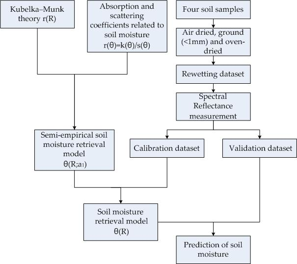
2. Materials and Methods
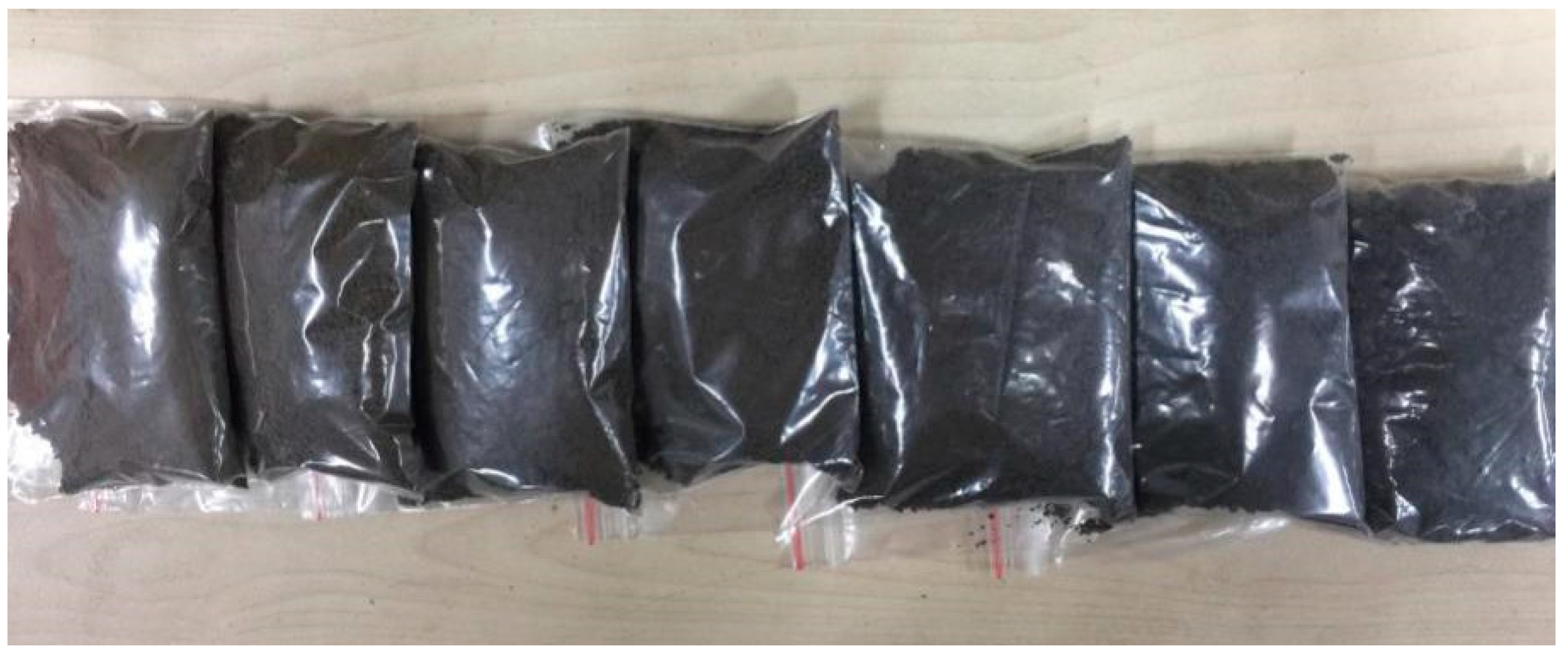
2.1. Soil Sample Preparation and Rewetting Experiment
2.2. Spectral Measurement and Pre-Processing
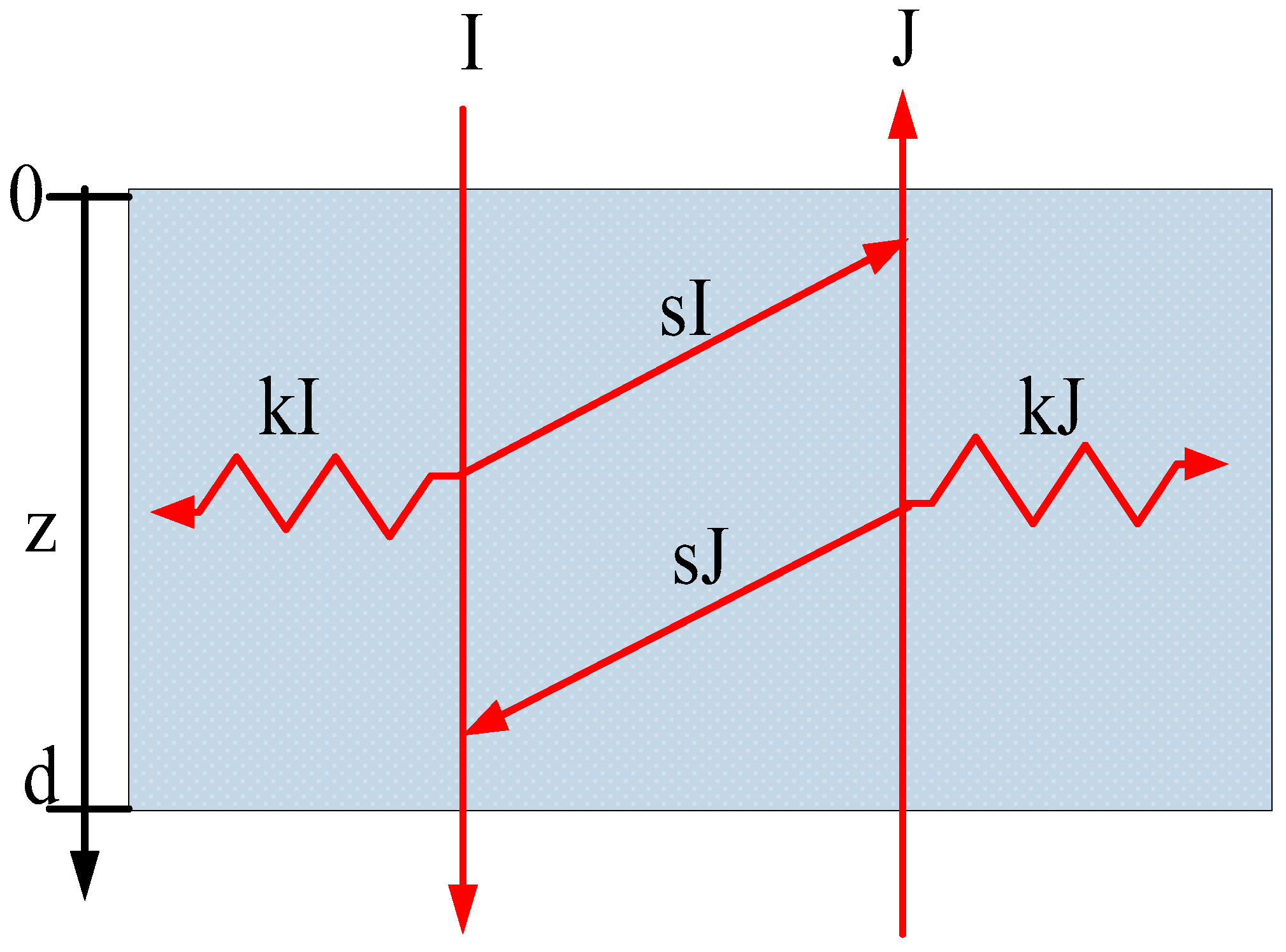
2.3. KM Model
2.4. SM Retrieval Model
2.5. Calibration and Validation
2.6. Unknown Parameter Acquirement
3. Results
3.1. Descriptive Statistics of SM
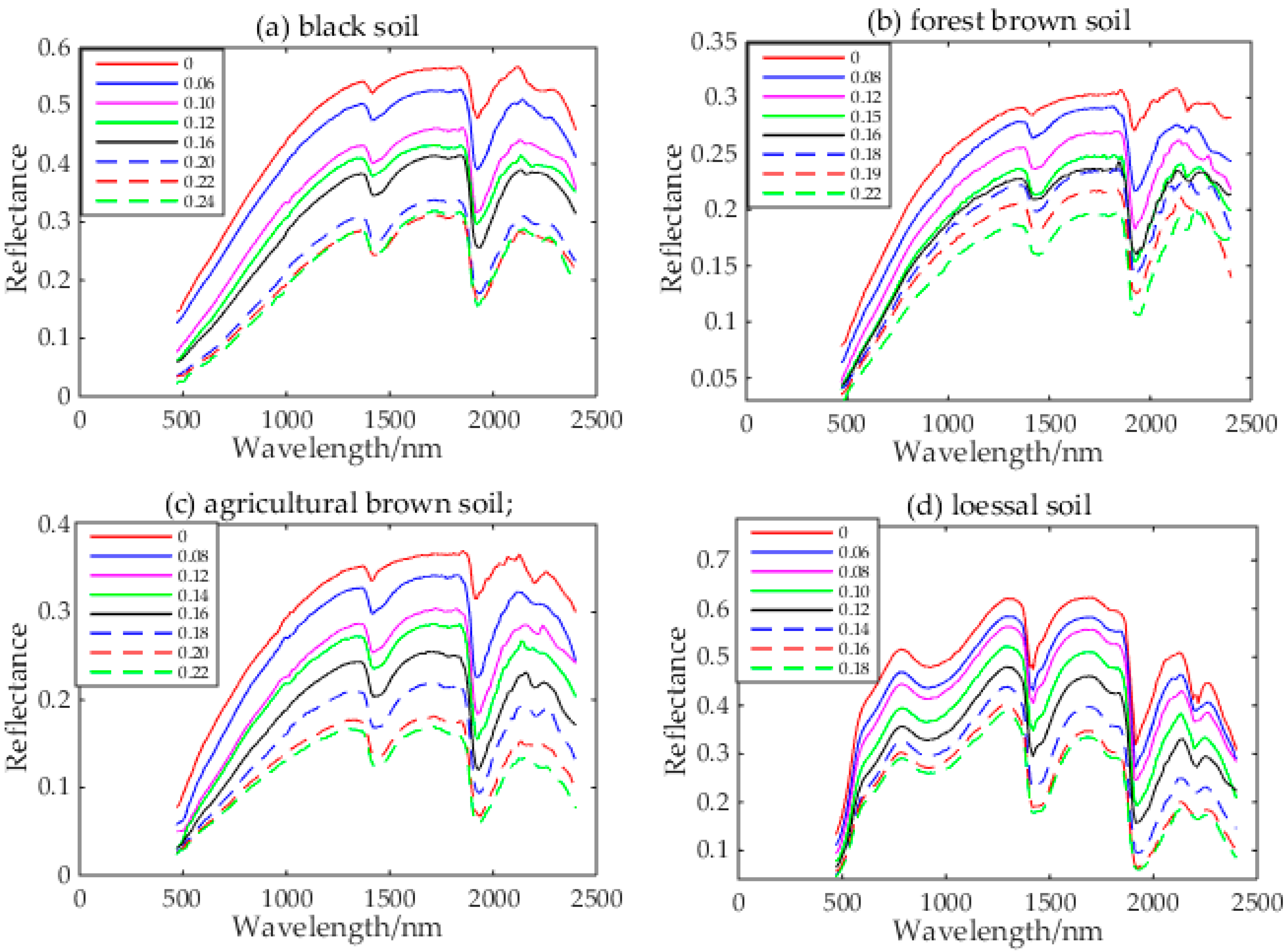
3.2. Reflectance Spectral Feature of Four Soils at Different SM Levels
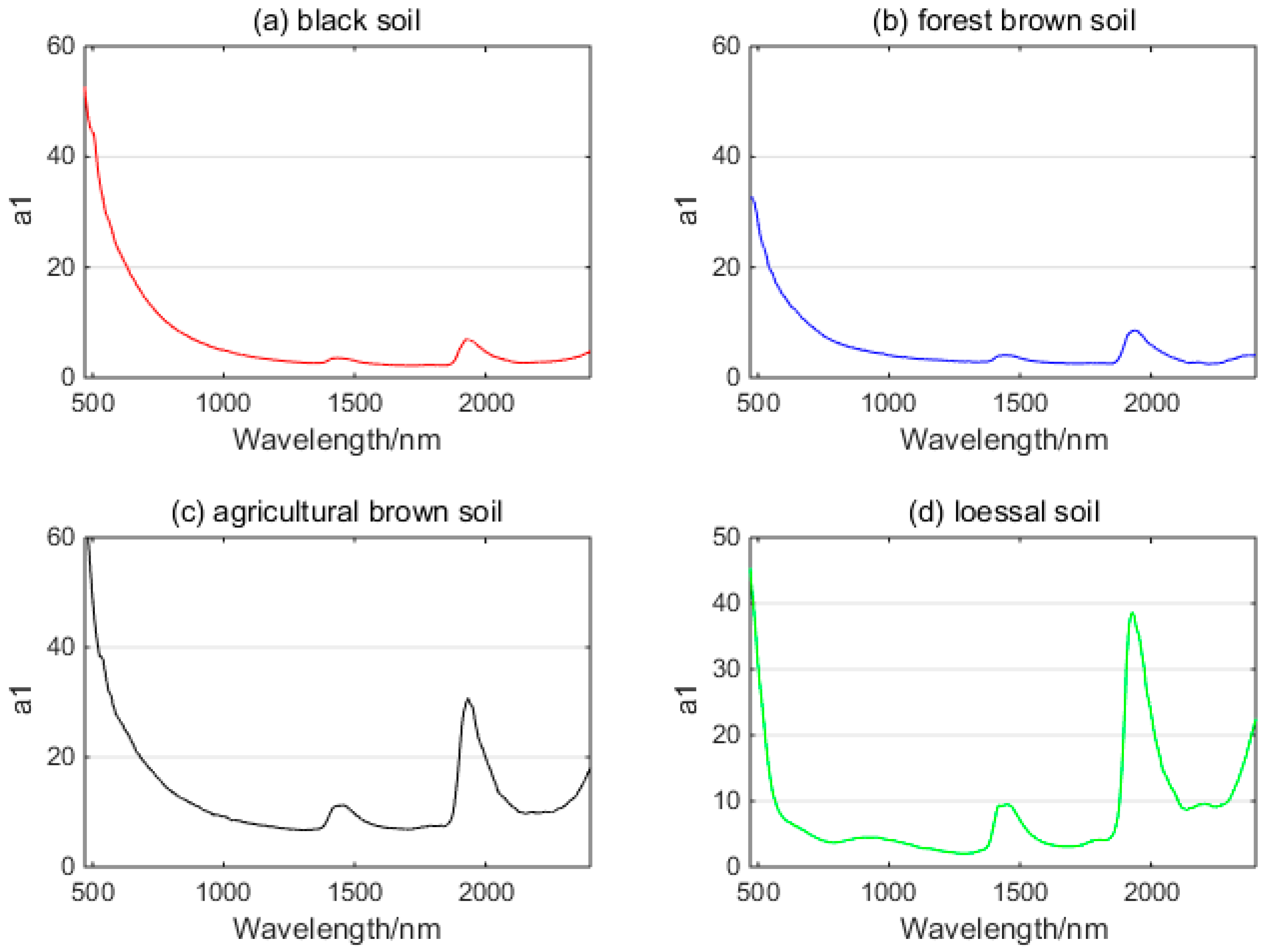
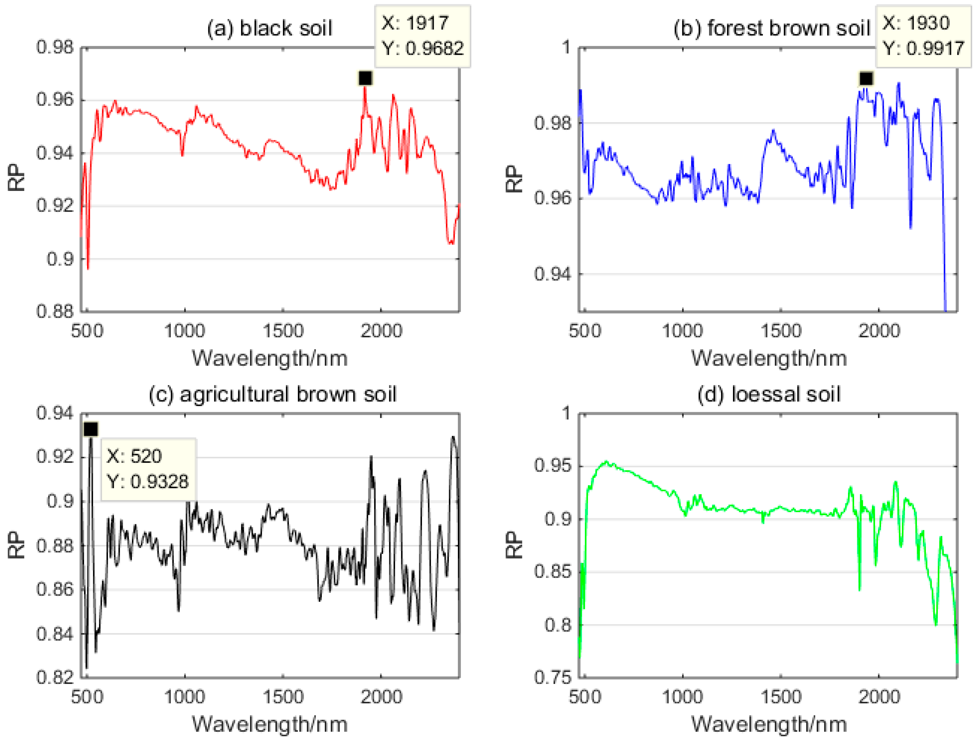
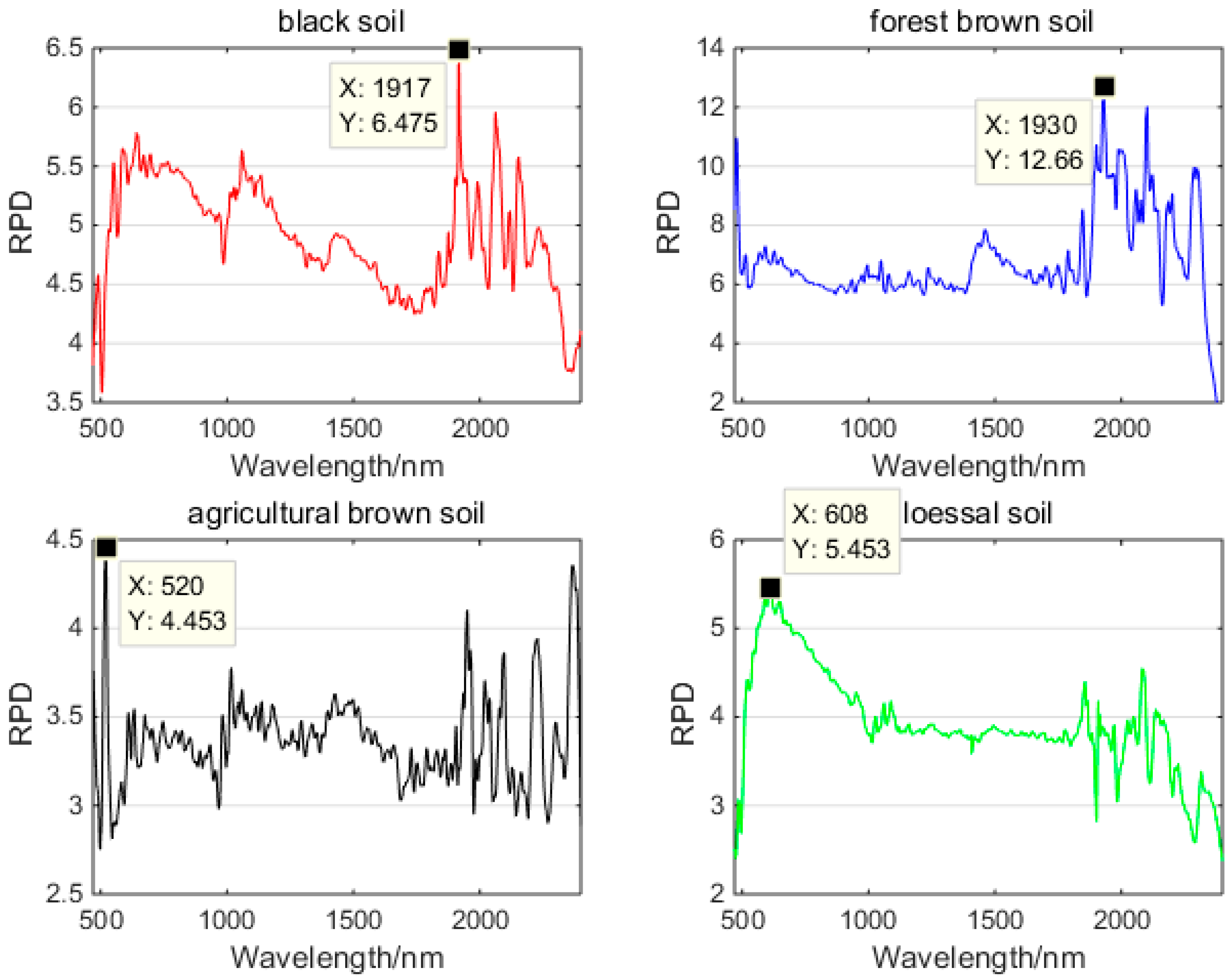
3.3. SM Retrieval Model
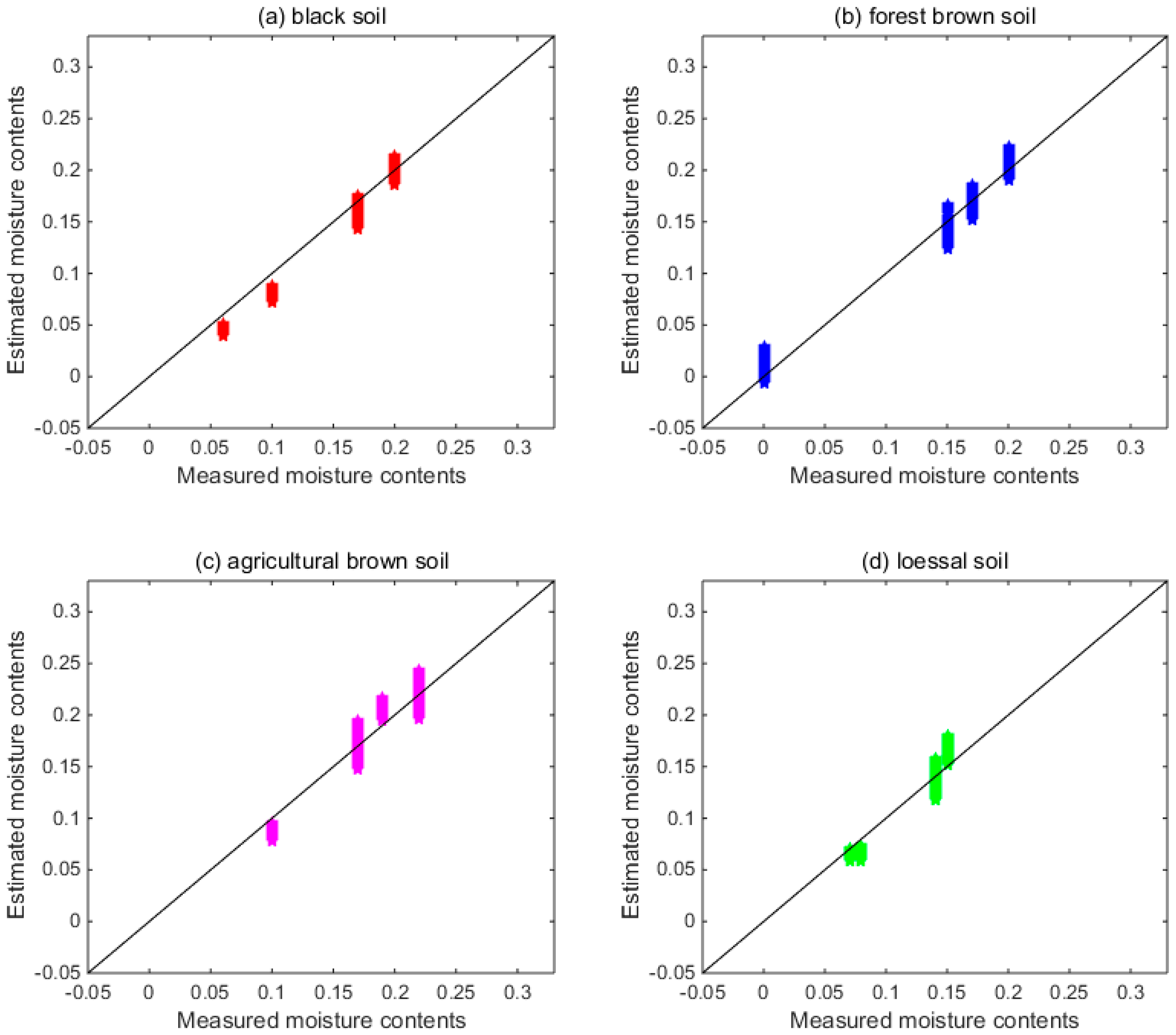
3.4. SM Estimation
4. Discussion
5. Conclusions
Author Contributions
Funding
Conflicts of Interest
References
- Zhao, C.J.; Yang, G.J.; Xue, X.Z.; Feng, H.K.; Shi, C.Y. Temporal-spatial analysis of farmland evapotranspiration based on complementary relationship model and IKONOS data. Trans. CSAE 2013, 29, 115–124. [Google Scholar]
- Jarihani, A.A.; Larsen, J.R.; Callow, J.N.; McVicar, T.R.; Johansen, K. Where does all the water go? Partitioning water transmission losses in a data-sparse, multi-channel and low-gradient dryland river system using modelling and remote sensing. J. Hydrol. 2015, 529, 1511–1529. [Google Scholar] [CrossRef]
- Merlin, O.; Escorihuela, M.J.; Mayoral, M.A.; Hagolle, O.; Al Bitar, A.; Kerr, Y. Self-calibrated evaporation-based disaggregation of SMOS soil moisture: An evaluation study at 3 km and 100 m resolution in Catalunya, Spain. Remote Sens. Environ. 2013, 130, 25–38. [Google Scholar] [CrossRef]
- Piles, M.; Camps, A.; Vall-llossera, M.; Corbella, I.; Panciera, R.; Rudiger, C. Downscaling SMOS-derived soil moisture using MODIS visible/infrared data. IEEE Trans. Geosci. Remote Sens. 2011, 49, 3156–3166. [Google Scholar] [CrossRef]
- Song, D.S.; Zhao, K.; Guan, Z. Advances in Research on Soil Moisture by Microwave Remote Sensing in China. Chin. Geogr. Sci. 2007, 17, 186. [Google Scholar] [CrossRef]
- Ghulam, A.; Qin, Q.M.; Zhan, Z.M. Designing of the perpendicular drought index. Environ. Geol. 2007, 52, 1045. [Google Scholar] [CrossRef]
- Lou, W.; Zhang, Y.B.; Alborz, F.; Zoltán, G.; Aydogan, O. Pixel super-resolution using wavelength scanning. Light Sci. Appl. 2016, 5, e16060. [Google Scholar] [CrossRef]
- Wang, L.S.; Lu, C.P.; Wang, R.J.; Huang, W.; Guo, H.Y.; Wang, Y.B.; Lin, Z.D.; Wang, J.; Jiang, J.; Song, L.T. Optimization for Vis/NIRS prediction model of soil available nitrogen content. Chin. J. Lumin. 2018, 39, 1016–1023. [Google Scholar] [CrossRef]
- Ma, J.W.; Song, X.N.; Li, X.T.; Leng, P.; Li, S.; Zhou, F.C. Estimation of surface soil moisture from ASAR dual-polarized data in the middle stream of the Heihe River Basin. Wuhan Univ. J. Nat. Sci. 2013, 2, 163–170. [Google Scholar] [CrossRef]
- Etienne, M.; Henri, D. Modeling soil moisture-reflectance. Remote Sens. Environ. 2001, 76, 173–180. [Google Scholar]
- Wijewardane, N.K.; Ge, Y.F.; Morgan, C.L.S. Moisture insensitive prediction of soil properties from VNIR reflectance spectra based on external parameter orthogonalization. Geoderma 2016, 267, 92–101. [Google Scholar] [CrossRef]
- Kornelsen, K.C.; Coulibaly, P. Advances in soil moisture retrieval from synthetic aperture radar and hydrological applications. J. Hydrol. 2013, 476, 460–489. [Google Scholar] [CrossRef]
- Wang, D.C.; Zhang, G.L.; Rossiter, D.G.; Zhang, J.H. The prediction of soil texture from visible-near-infraredspectra under varying moisture conditions. Soil Sci. Soc. Am. J. 2016, 80, 420–427. [Google Scholar] [CrossRef]
- Lievens, H.; Verhoest, N.E.C. Spatial and temporal soil moisture estimation from RADARSAT-2 imagery over Flevoland, The Netherlands. J. Hydrol. 2012, s456–s457, 44–56. [Google Scholar] [CrossRef]
- Yuan, J.; Wang, X.; Yan, C.X. A Semi-empirical Model for Reflectance Spectral of Black Soil with Different Moisture Contents. Spectrosc. Spectr. Anal. accepted.
- Hapke, B.W. Theory of Reflectance and Emittance Spectroscopy, 2nd ed.; Cambridge University Press: Cambridge, UK, 2012. [Google Scholar]
- Liu, W.D.; Frederic, B.; Zhang, B.; Zheng, L.F.; Tong, Q.X. Extraction of soil moisture information by hyperspectral remote sensing. Acta Pedologica Sinica 2004, 41, 700–706. [Google Scholar]
- Deng, R.R.; Tian, G.L.; Liu, Q.H. Research on remote sensing model for soil water on rough surface. J. Remote Sens. 2004, 8, 75. [Google Scholar]
- Whiting, M.L.; Li, L.; Ustin, S.L. Predicting water content using Gaussian model on soil spectra. Remote Sens. Environ. 2004, 89, 535–552. [Google Scholar] [CrossRef]
- Yang, G.J.; Zhao, C.J.; Huang, W.J. Extension of the Hapke bidirectional reflectance model to retrieve soil water content. Hydrol. Earth Syst. Sci. 2011, 15, 2317–2326. [Google Scholar] [CrossRef]
- Sadeghi, M.; Jones, S.B.; Philpot, W.D. A linear physically-based model for remote sensing of soil moisture using short wave infrared bands. Remote Sens. Environ. 2015, 164, 66–76. [Google Scholar] [CrossRef]
- Ångström, A. The albedo of various surfaces of ground. Geogr. Ann. 1925, 7, 323–342. [Google Scholar]
- Lekner, J.; Dorf, M.C. Why some things are darker when wet. Appl. Opt. 1988, 27, 1278–1280. [Google Scholar] [CrossRef] [PubMed]
- Bach, H.; Mauser, W. Modeling and model verification of the spectral reflectance ofsoils under varying moisture conditions. Proc. IEEE IGARSS 1994, 4, 2354–2356. [Google Scholar]
- Kimmel, B.W.; Baranoski, G.V.G. A novel approach for simulating light interaction with particulate materials: Application to the modeling of sand spectral properties. Opt. Express 2007, 15, 9755–9777. [Google Scholar] [CrossRef] [PubMed]
- Philpot, W.D. Symposium: Art, Science and Applications of Reflectance Spectroscopy (ASARS); Analytical Spectral Devices, Inc.: Boulder, CO, USA, 2010; pp. 23–25. [Google Scholar]
- Sun, Y.J.; Zheng, X.P.; Qin, Q.M.; Meng, Q.Y.; Gao, Z.L.; Ren, H.Z.; Wu, L.; Wang, J.; Wang, J.H. Modeling soil spectral reflectance with different mass moisture content. Spectrosc. Spectr. Anal. 2015, 35, 2236–2240. [Google Scholar]
- Hassan Esfahani, L.; Torres-Rua, A.; Jensen, A.; Mc Kee, M. Assessment of surface soil moisture using high-resolution multi-spectral imagery and artificial neural net-works. Remote Sens. 2015, 7, 2627–2646. [Google Scholar] [CrossRef]
- Zaman, Z.; Mc Kee, M.; Neale, C.M.U. Fusion of remotely sensed data for soil moisture estimation using relevance vector and support vector machines. Int. J. Remote Sens. 2012, 33, 6516–6552. [Google Scholar] [CrossRef]
- Wu, L.G.; Wang, S.L.; He, J.G.; Kazuhiro, N. Soil moisture mechanism and establishment of model based on hyperspectral imaging technique. Chin. J. Lumin. 2017, 38, 1366–1376. [Google Scholar]
- Wang, R.J.; Chen, T.J.; Wang, Y.B.; Wang, L.S.; Xie, C.J.; Zhang, J.; Li, R.; Chen, H.B. Soil near-infrared spectroscopy prediction model based on deep sparse learning. Chin. J. Lumin. 2017, 38, 109–116. [Google Scholar] [CrossRef]
- Wang, X.Q.; Sun, X.B.; Zhang, L.Y.; Wang, J.J.; Xie, Q.R.; Ye, S. Experimental study on visible and near-infrared spectrum polarization characteristic of soil moisture. Infrared Laser Eng. 2015, 44, 3288–3292. [Google Scholar]
- Zhao, Y.Q.; Pan, Q.; Chen, Y.M. Imaging Spectropolarimetric Remote Sensing and Application, 1st ed.; National Defence Industry Press: Beijing, China, 2011; pp. 104–105. ISBN 978-7-118-07397-3. [Google Scholar]
- Conforti, M.; Buttafuoco, G.; Leone, A.P.; Aucelli, P.P.C.; Robustelli, G.; Scarciglia, F. Studying the relationship between moisture-induced soil erosion and soil organic matter using vis-nir spectroscopy and geomorphological analysis: A case study in southern Italy. Catena 2013, 110, 44–58. [Google Scholar] [CrossRef]
- Kubelka, P.; Munk, F. Ein Beitrag zur Optik der Farbanstriche. Zeitschrift fürTechnische Physik 1931, 12, 593–601. [Google Scholar]
- Vargas, W.E.; Niklasson, G.A. Applicability conditions of the Kubelka–Munk theory. Appl. Opt. 1997, 36, 5580–5586. [Google Scholar] [CrossRef] [PubMed]
- Wendlandt, W.W.; Hecht, H.G. Reflectance Spectroscopy; John Wiley & Sons: New York, NY, USA, 1966. [Google Scholar]
- Ciani, A.; Goss, K.U.; Schwarzenbach, R.P. Light penetration in soil and particu-late minerals. Eur. J. Soil Sci. 2005, 56, 561–574. [Google Scholar] [CrossRef]
- Le Hors, L.; Hartemann, P.; Dolfi, D.; Breugnot, S. A phenomenological model of paints for multispectral polarimetric imaging. Proc. SPIE 2001, 4370, 94–105. [Google Scholar]
- Barron, V.; Torrent, J. Use of the Kubelka–Munk theory to study the influence of iron oxides on soil color. J. Soil Sci. 1986, 37, 499–510. [Google Scholar] [CrossRef]
- Hu, X.; Johnston, W.M. Concentration additivity of coefficients for maxillofacial elastomer pigmented to skin colors. Dent. Mater. 2009, 25, 1468–1473. [Google Scholar] [CrossRef] [PubMed]
- Terhoeven-Urselmans, T.; Vagen, T.-G.; Spaargaren, O.; Shepherd, K.D. Prediction of soil fertility properties from a globally distributed soil mid-infrared spectral library. Soil Sci. Soc. Am. J. 2010, 74, 1792–1799. [Google Scholar] [CrossRef]
- Chang, C.W.; Laird, D.A.; Mausbach, M.J.; Hurburgh, C.R. Near-infrared reflectance spectroscopy–principal components regression analyses of soil properties. Soil Sci. Soc. Am. J. 2001, 65, 480–490. [Google Scholar] [CrossRef]
- Liu, Y.; Ding, X.; Liu, H.J.; Zhang, X.L.; Qu, C.X.; Hu, W.; Zang, H.T. Quantitative analysis of reflectance spectrum of black soil as affected by soil moisture for prediction of soil moisture in black soil. Acta Pedol. Sin. 2014, 51, 1021–1026. [Google Scholar]
- Yang, M.; Fang, Y.H.; Wu, J.; Cui, F.X. Study of polarized reflectance properties based on six-component pBRDF model for ground-feature’s background. Acta Opt. Sin. 2018, 38, 0526001. [Google Scholar] [CrossRef]
- Zhan, H.Y.; David, G.V.; Xiao, X.F.; Cho, S.Y. Polarization-based complex index of refraction estimation with diffuse scattering consideration. Polariz. Sci. Remote Sens. VII 2015, 96130. [Google Scholar] [CrossRef]
- Pope, R.M.; Fry, E.S. Absorption spectrum (380–700 nm) of pure water. II. Integrating cavity measurements. Appl. Opt. 1997, 36, 8710–8723. [Google Scholar] [CrossRef] [PubMed]
- Segelstein, D.J. The Complex Refractive Index of Water. Master’s Thesis, Department of Physics, University of Missouri-Kansas City, Kansas City, MO, USA, 1981. [Google Scholar]
- Haubrock, S.N.; Chabrillat, S.; Lemmnitz, C.; Kaufmann, H. Surface soil moisture quantification models from reflectance data under field conditions. Int. J. Remote Sens. 2008, 29, 3–29. [Google Scholar] [CrossRef]


| Optical Model | Author | Key Results |
|---|---|---|
| Semi-empirical model | Liu et al. (2004) | Adopted the methods of relative reflectance, first-order differential and difference in the prediction and modeling of soil surface moisture. |
| Deng et al. (2004) | Established a moisture content model of rough soil based on the physical process of soil spectral scattering. | |
| Whiting et al. (2004) | Fitted an inverted Gaussian function to the continuum and calibrated the area below the curve to soil moisture content (SMC). | |
| Yang et al. (2011) | Established the soil water parametric (SWAP)–Hapke model by introducing the soil water content information into the soil bidirectional reflectance model (SOILSPECT). | |
| Sadeghi et al. (2015) | Proposed a model based on the Kubelka–Munk (KM) two-flux radiative transfer model. | |
| This study | Established a SM retrieval model using the absorption coefficient and scattering coefficient related to SM based on KM theory. | |
| Physical model | Ångström (1925) | Proposed a simple model where a wet soil is regarded as a dry soil covered with a thin film of liquid water. |
| Lekner and Dorf (1988) | Improved the Ångström model by using the Fresnel coefficients instead of Snell’s law | |
| Bach and Mauser (1994) | Introduced the Beer–Lambert–Bouguer law to account for light absorption in the water layer and extended the model to the visible light-short-wave infrared (VIS-SWIR) | |
| Kimmel and Baranoski (2007) | Published a ray tracing model called SPLITS (spectral light transport model for sand) | |
| Philpot (2010) | Proposed a simple waterborne soil reflectance spectrum simulation model | |
| Sun et al. (2015) | Improved the Philpot model by exploring the relationship between the soil water content and two parameters | |
| Empirical/statistical model | Zaman et al. (2012) | Established a moisture content model using relevance vector machines and support vector machines |
| Hassan Esfahani et al. (2015) | Developed an artificial neural network (ANN) model to quantify the effectiveness of using spectral images to estimate surface SM | |
| Wang et al. (2017) | Proposed a soil near-infrared spectroscopy prediction model based on deep sparse learning | |
| Wang et al. (2015) | Developed a regression model between polarization and SM. | |
| Wu et al. (2015) | Developed a SM prediction model with multiple linear regression, principal component regression, and partial least-squares regression, respectively |
| Soil Name | Sand Contents/% | Silt Contents/% | Clay Contents/% | Mineralogical Composition |
|---|---|---|---|---|
| Black soil | 40.63 | 24.87 | 34.50 | Illite, montmorillonite |
| Forest brown soil | 19.22 | 40.06 | 40.72 | Hydromica, montmorillonite, and kaolinite |
| Agricultural brown soil | 26.92 | 45.01 | 28.07 | Hydromica, kaolinite, and vermiculite |
| Loessial soil | 28.36 | 17.89 | 53.75 | Kaolinite, illite, and montmorillonite |
| Soil | Dataset Name | Number | Maximum | Minimum | Mean | SD | CV (%) |
|---|---|---|---|---|---|---|---|
| Black soil | whole | 14 | 0.24 | 0 | 0.1421 | 0.0662 | 46.6 |
| calibration | 10 | 0.24 | 0 | 0.1460 | 0.0701 | 48.02 | |
| validation | 4 | 0.2 | 0.06 | 0.1325 | 0.0640 | 48.28 | |
| Forest brown soil | whole | 14 | 0.22 | 0 | 0.1393 | 0.0566 | 40.66 |
| calibration | 10 | 0.22 | 0.08 | 0.1430 | 0.0440 | 30.76 | |
| validation | 4 | 0.2 | 0 | 0.1300 | 0.0891 | 68.51 | |
| Agricultural brown soil | whole | 15 | 0.23 | 0 | 0.1493 | 0.0649 | 43.43 |
| calibration | 11 | 0.23 | 0 | 0.1418 | 0.0698 | 49.24 | |
| validation | 4 | 0.22 | 0.1 | 0.1700 | 0.0510 | 30.00 | |
| Loessial soil | whole | 13 | 0.18 | 0.04 | 0.1092 | 0.0427 | 39.10 |
| calibration | 9 | 0.18 | 0.04 | 0.1089 | 0.0459 | 42.20 | |
| validation | 4 | 0.15 | 0.07 | 0.1100 | 0.0408 | 37.11 |
| Soil | Moisture Contents | RMSE |
|---|---|---|
| Black soil | 0.06 | 0.0159 |
| 0.10 | 0.0181 | |
| 0.17 | 0.0088 | |
| 0.02 | 0.0063 | |
| Forest brown soil | 0.00 | 0.0218 |
| 0.15 | 0.0130 | |
| 0.17 | 0.0054 | |
| 0.20 | 0.0062 | |
| Agricultural brown soil | 0.10 | 0.0171 |
| 0.17 | 0.0118 | |
| 0.19 | 0.0189 | |
| 0.22 | 0.0118 | |
| Loessial soil | 0.07 | 0.0061 |
| 0.08 | 0.0160 | |
| 0.14 | 0.0053 | |
| 0.15 | 0.0118 |
| Wavelength | 480 nm | 560 nm | 660 nm | 830 nm | 1650 nm | 2210 nm | |
|---|---|---|---|---|---|---|---|
| Black soil | Concentration gradient | 0.0148 | 0.0116 | 0.0119 | 0.0112 | 0.0147 | 0.0134 |
| Minimum | 0.0106 | 0.0083 | 0.0087 | 0.0062 | 0.0107 | 0.0102 | |
| Maximum | 0.0335 | 0.0225 | 0.0220 | 0.0209 | 0.0254 | 0.0230 | |
| Mean | 0.0260 | 0.0149 | 0.0149 | 0.0152 | 0.0180 | 0.0182 | |
| Forest brown soil | Concentration gradient | 0.0082 | 0.0135 | 0.0131 | 0.0150 | 0.0136 | 0.0117 |
| Minimum | 0.0025 | 0.0059 | 0.0046 | 0.0069 | 0.0109 | 0.0099 | |
| Maximum | 0.0283 | 0.0188 | 0.0183 | 0.0201 | 0.0261 | 0.0358 | |
| Mean | 0.0168 | 0.0121 | 0.0117 | 0.0135 | 0.0220 | 0.0297 | |
| Agricultural brown Soil | Concentration gradient | 0.0155 | 0.0176 | 0.0159 | 0.0154 | 0.0156 | 0.0135 |
| Minimum | 0.0034 | 0.0067 | 0.0078 | 0.0054 | 0.0072 | 0.0121 | |
| Maximum | 0.0284 | 0.0236 | 0.0220 | 0.0215 | 0.0195 | 0.0275 | |
| Mean | 0.0141 | 0.0170 | 0.0164 | 0.0152 | 0.0161 | 0.0181 | |
| Loessial soil | Concentration gradient | 0.0152 | 0.0087 | 0.0077 | 0.0090 | 0.0106 | 0.0121 |
| Minimum | 0.0055 | 0.0048 | 0.0029 | 0.0040 | 0.0053 | 0.0075 | |
| Maximum | 0.0257 | 0.0151 | 0.0132 | 0.0125 | 0.0157 | 0.0144 | |
| Mean | 0.0160 | 0.0101 | 0.0086 | 0.0084 | 0.0121 | 0.0123 | |
© 2019 by the authors. Licensee MDPI, Basel, Switzerland. This article is an open access article distributed under the terms and conditions of the Creative Commons Attribution (CC BY) license (http://creativecommons.org/licenses/by/4.0/).
Share and Cite
Yuan, J.; Wang, X.; Yan, C.-x.; Wang, S.-r.; Ju, X.-p.; Li, Y. Soil Moisture Retrieval Model for Remote Sensing Using Reflected Hyperspectral Information. Remote Sens. 2019, 11, 366. https://doi.org/10.3390/rs11030366
Yuan J, Wang X, Yan C-x, Wang S-r, Ju X-p, Li Y. Soil Moisture Retrieval Model for Remote Sensing Using Reflected Hyperspectral Information. Remote Sensing. 2019; 11(3):366. https://doi.org/10.3390/rs11030366
Chicago/Turabian StyleYuan, Jing, Xin Wang, Chang-xiang Yan, Shu-rong Wang, Xue-ping Ju, and Yi Li. 2019. "Soil Moisture Retrieval Model for Remote Sensing Using Reflected Hyperspectral Information" Remote Sensing 11, no. 3: 366. https://doi.org/10.3390/rs11030366
APA StyleYuan, J., Wang, X., Yan, C.-x., Wang, S.-r., Ju, X.-p., & Li, Y. (2019). Soil Moisture Retrieval Model for Remote Sensing Using Reflected Hyperspectral Information. Remote Sensing, 11(3), 366. https://doi.org/10.3390/rs11030366