1. Introduction
With the rapid development of robotics, the localization and navigation of mobile robots have attracted the attention of many scholars [
1,
2], and it has become a hot-spot in the field of robotics research. Currently, the localization and navigation of robots mainly rely on SLAM (Simultaneous Localization and Mapping) [
3], which can conduct real-time localization and environmental reconstruction in the unknown environment.
The current SLAM technology mainly includes Lidar-based SLAM [
4] and Vision-based SLAM [
5]. Laser SLAM is a relatively mature method of SLAM, which has been successfully applied to a variety of commercial products. However, the map information constructed by Lidar-based SLAM is too simple to enable the robot to obtain more abundant environmental information for other intelligent tasks. Visual SLAM has been a rapidly developing SLAM solution in the past ten years, which can reconstruct 3D environment maps using a camera sensor. Besides, the image contains a wealth of object information which can help the robot complete a variety of intelligent tasks based on vision. ORB-SLAM [
6], proposed in 2015, is the representative of visual SLAM. With the support of various optimization mechanisms, its real-time and positioning accuracy is at a high level, but there are still some problems, such as monocular scale uncertainty and tracking loss. ORB-SLAM2 [
7], which was proposed in 2016 as an improved version of ORB-SLAM, added support for the stereo camera and RGB-D camera, as well as improved robustness against environmental changes and violent movement; however, when the target platform is a mobile robot, ORB-SLAM2 has the following disadvantages:
Slow start-up. The ORB-SLAM2 system needs to read a large-scale text format vocabulary for loop closure detection during start-up, but after testing, the process is very time-consuming and takes up most of the time spent in the start-up process.
The vocabulary has a large amount of invalid data when the robot’s working environment is relatively fixed. ORB-SLAM2 provides a vocabulary based on a large dataset, which enables ORB-SLAM2 to maintain high accuracy in different environments. However, when the working environment of the robot is relatively fixed, it still takes much time to read a large amount of invalid data in the vocabulary.
The map cannot be saved and reused. ORB-SLAM2 cannot save and load maps, so the robot needs to "relearn" its work environment when it starts up every time. If the ORB-SLAM2 system could save the map and reuse it, it would save many computing resources and improve the efficiency of the robot.
Lack of offline visualization of map and trajectory. ORB-SLAM2 provides real-time visualization, but users usually do not pay attention to the real-time status of the mapping but view the map and track information after the system is finished. However, ORB-SLAM2 does not provide offline visualization of maps and mapping trajectories.
Because of the above disadvantages of the ORB-SLAM2 system, this paper proposed a rapid relocation method for the mobile robot based on an improved ORB SLAM2 algorithm.
The main contributions of this paper are summarized as follows:
A binary-based vocabulary storage method is designed to convert the text-format vocabulary into a binary format without data loss. This method can improve the vocabulary loading speed of the system.
A vocabulary training algorithm is proposed based on an improved ORB operator, which is used to train the small-scale vocabulary to improve localization accuracy and reduce vocabulary size.
An offline map construction algorithm is proposed based on map elements and a keyframe database, and we also designed a fast relocation method based on the offline map.
We designed an offline visualization method for the map and mapping trajectory of the ORB-SLAM2 system.
The rest of the paper is organized as follows.
Section 2 is a review and analysis of related research.
Section 3 introduces the main threads and core algorithms of ORB-SLAM2.
Section 4 presents our improvements to the ORB-SLAM2 algorithm. In
Section 5, we test and analyze the method of this paper based on the robot platform.
Section 6 summarizes this paper and discusses future research directions.
2. Related Work
In order to make Visual SLAM better for mobile robots, Davison et al. proposed MonoSLAM [
8] as the first high frame-rate, real-time Monocular SLAM solution. The algorithm creates a sparse but stable map of landmarks based on a probabilistic framework, and solved the problem of monocular feature initialization, among others. However, as this work was based on the EKF (Extended Kalman Filter) algorithm [
9], it caused a problem with error drift; the landmarks map are also sparse, making it easy for the system to lose tracking. In order to solve the linearization error caused by the EKF, UKF (Unscented Kalman Filter) [
10] and improved UKF [
11] were proposed and applied to Visual SLAM to improve the linearization uncertainty. Moreover, Sim et al. [
12] proposed a particle filter-based monocular SLAM algorithm to avoid linearization. However, although the above method improves accuracy, it also greatly increases the computational complexity. Klein and Murray et al. [
13] proposed a keyframe-based monocular SLAM algorithm, called PTAM (parallel tracking and mapping). The algorithm introduced a keyframe extraction method, and for the first time, divided the tracking and mapping into two parallel threads. Besides, PTAM used nonlinear optimization instead of the EKF method to eliminate the linearization error problem, which improved the location accuracy of the system. However, this study did not pay attention to the global optimization problem of the PTAM, which caused the system to lose tracking easily in a large-scale environment. Engel et al. proposed the Large-Scale Direct Monocular SLAM (LSD-SLAM) [
14] algorithm, which is the monocular SLAM algorithm based on the direct method. LSD-SLAM can construct a semi-dense global consistent map, which is a more complete representation of the environmental structure than a point-cloud map based on the feature method. In addition, LSD-SLAM presents a novel direct tracking method which can accurately detect scale drift, and the algorithm can run in real time on the Central Processing Unit (CPU). However, this work still did not solve the gray-scale invariant hypothesis of the direct method, which made the performance of LSD-SLAM decrease rapidly when the robot was working in an environment with frequent illumination changes.
Focusing on the localization and navigation of the robot in an indoor environment, Brand et al. [
15] proposed an on-board SLAM algorithm for mobile robots operating in an unknown indoor environment, where the algorithm introduced local 2.5D maps which could be directly employed for fast obstacle avoidance and local path planning, and which also constituted a suitable input for a 2D grid map SLAM. Lee et al. [
16] proposed a SLAM algorithm based on autonomous detection and the registration of objects. This algorithm helps the robot to identify the object without relying on any a priori information, and inserts the detected objects as landmarks into the grid map. The new map has a certain improvement in positioning and navigation accuracy compared to the traditional pure visual SLAM. However, both studies ignored the importance of the 3D map, and they also cannot reconstruct a complete environmental structure, which made them lose the most important advantage of visual SLAM. Considering how the sparse map cannot be applied to obstacle avoidance and navigation, Qiang et al. [
17] proposed a dense 3D reconstruction method based on the ORB-SLAM algorithm. The method enables the ORB-SLAM system to construct an octomap [
18] based on the octrees and probabilistic occupancy estimation, and the improved ORB-SLAM can complete the map reconstruction in real time using a Kinect 2.0 camera in the real world. However, this work cannot express the working environment intuitively because of the use of octomap, so we could not directly check the mapping effect, which reduced the interactivity of the robot.
Researchers have made a lot of effort to try and optimize the performance of ORB-SLAM2. Wang et al. [
19] proposed a monocular SLAM algorithm based on the fusion of IMU (Inertial Measurement Unit) information and ORB-SLAM2 pose information. The algorithm can determine the scale information and make-up for the pose information when the pure monocular visual SLAM tracking is lost. Caldato et al. [
20] proposed a tightly sensor fusion method to improve the tracking results of visual odometry when the robot works in featureless environments. This algorithm integrated image data and odometer data to improve graph constraints between frames and prevent tracking loss. However, although the above two studies improved the robustness of the ORB-SLAM2 system, they increased the occupation of robot computing resources. The improvements of the two papers were also mainly focused on dealing with unexpected situations of tracking, and did not improve the performance of the system under a normal tracking state. In order to solve the problem of how ORB-SLAM2 cannot distinguish 3DOF (degrees of freedom) image frames and 6DOF image frames, Zeng et al. [
21] proposed a 6DOF keyframe selection method to avoid wrong triangulation to 3DOF keyframes. However, since the 3DOF keyframes are filtered out, the number of keyframes in the map or keyframe database is reduced, thereby reducing the accuracy of loop detection and relocation, which ultimately leads to degradation of the performance of the ORB-SLAM2 system. Senbo et al. [
22] introduced a unified spherical camera model to extend the ORB-SLAM2 framework. The model enables the system to obtain a larger perceiving region by using fisheye cameras. In addition, it proposed a semi-dense feature-matching method, which can make use of high-gradient regions as semi-dense features to construct the semi-dense map, thereby providing richer environment information than a sparse feature map. However, the mapping error is relatively high when the robot is working in a large-scale environment, and although this work reconstructed a complete environment, it ignored the extended application and reuse of semi-dense map information.
3. ORB-SLAM2
ORB-SLAM2 [
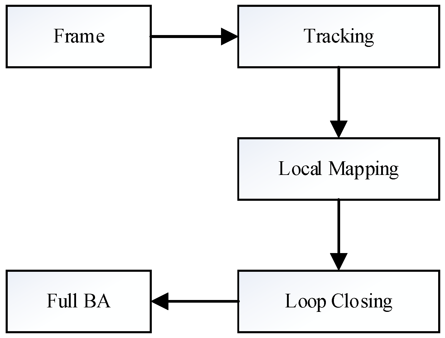
7], which was proposed by R Mur-Artal, added support for the stereo camera and RGB-D camera outside of the monocular camera. As shown in
Figure 1, the system framework of ORB-SLAM2 mainly contains three parallel threads: Tracking, Local Mapping, and Loop Closing.
3.1. Tracking
The main task of the tracking thread is to estimate the camera pose for each frame of the input image based on the feature method. There are three tracking models in the tracking thread: the motion model, keyframe model, and relocation model. The tracking state of the system is affected by factors such as environmental changes, and the tracking thread selects the tracking model according to different tracking states.
ORB-SLAM2 estimates the camera pose by building a PnP (Perspective-
n-Point) [
23] model. There are several methods for the PnP problem, such as P3P [
24], DLT (Direct Linear Transformation) [
25], EPnP (Efficient PnP) [
26], etc. EPnP is the pose estimation algorithm used by the relocation tracking model, and it is also one of the best accurate PnP problem-solving algorithms.
3.2. Local Mapping
The local mapping thread is mainly responsible for receiving and processing new keyframes, checking new map points, maintaining the accuracy of local maps, and controlling the quality and scale of keyframe sets. The workflow is as follows:
(1) Process new keyframes: First, calculate the BoW (Bag-of-Words) [
27] vector of the current keyframe, update the map point observation values of the keyframe, and put these map points on the new map point list; then, update the Covisibility graph and Essential graph, and add the current keyframe to the map.
(2) Filter map points: Rule out redundant points by checking the list of new map points. The culling rules are as follows: (a) The map point is marked as a bad point; (b) the number of keyframes that can observe the map point is no more than 25% or three (the threshold is two when the sensor is a monocular camera).
(3) Restore new map points based on the current keyframe: First, select the keyframes connected to the current keyframe from the Covisibility graph, and then perform feature-matching on the current keyframe and the selected keyframes, and calculate the pose of the current keyframe by the epipolar geometry; after that, the feature-point depth is restored by the triangulation method. Finally, the re-projection error of the new map point is calculated according to the depth of the feature point obtained, and whether the map point is eliminated or not is determined according to the relationship between the error and the given threshold value.
(4) Local BA (Bundle Adjustment): When new keyframes are added to the Covisibility graph, iterate optimization is performed and the outer points are removed to optimize the pose of the locally connected keyframes.
(5) Filter local keyframe: The rule for ORB-SLAM2 to remove redundant keyframes is, if 90% of the map points observed by the keyframe can be observed by the other three or more keyframes simultaneously, delete this keyframe.
3.3. Loop Closing
Loop Closing contains loop detection and loop correction.
The task of loop detection is to screen and confirm the loop closure. First, calculate the BoW score of the current keyframe and the connected keyframe, and select the closed-loop candidate frame by the lowest threshold. The independent keyframes of low quality are eliminated by calculating the number of shared words and the cluster score, and the remaining candidate keyframes are continuously detected. After detecting the loop closure, the similarity transformation Sim3 is solved by the RANSAC (Random Sample Consensus) [
28] framework, and then Sim3 is optimized by re-matching and g2o (General Graphic Optimization) [
29] to correct the pose of the current keyframe.
Loop correction is responsible for eliminating global cumulative errors. First, adjust the pose of the keyframe connected to the current keyframe by the propagation method. Then, project the updated map points to the corresponding keyframes and fuse the matching map points. Finally, update the connection relationship of keyframes according to the adjusted map points. After the map fusion is completed, perform the pose graph optimization by the essential graph.
4. Improved ORB-SLAM2 Algorithms
In this section, we proposed an improved ORB-SLAM2 algorithm to improve the disadvantages of ORB-SLAM2 mentioned above. The specific improvements include the binary-based vocabulary storage method, vocabulary training algorithm for improved ORB operator, offline map construction and preservation method, and robot relocation method, based on the offline map.
4.1. Binary-Based Vocabulary Storage Method
ORB-SLAM2 provides a vocabulary for training through large-scale data, and the authors implemented a function to save the vocabulary as a text format in order to enable the system to load the vocabulary directly. However, the text file needs to process the data format and line breaks during the loading process, and the time consumption is very large when the vocabulary data size is large. At the same time, we noticed that the binary file is non-interpretable and can be read directly without complicated data conversion and line-break processing, so it has high reading efficiency. Based on the above facts, in order to improve the vocabulary loading speed of the ORB-SLAM2 system, a binary-based vocabulary storage method (Algorithm 1) is proposed.
| Algorithm 1: Binary-Based Vocabulary Storage Method |
Input: A text format vocabulary
Output: A binary format vocabulary
- 1)
Load the vocabulary data in text format and create a vector Vnode that includes all the nodes, then read the number of nodes Nnode and the size of nodes Nsize; - 2)
Create an empty binary file Fb; - 3)
Write the Nnode, Nsize, number of branches K, vocabulary tree depth L, node weight type Wnode, similarity score calculation method Ssim into Fb; - 4)
For each node Vinode ∈ Vnode (i from 1 to Nnode): - a)
Write the parent node of Vinode into Fb; - b)
Write the feature descriptor of Vinode into Fb; - c)
Write the weight of Vinode into Fb; - d)
Write a Boolean value to indicate the node property to know whether it is a leaf node.
- 5)
Save Fb as the binary format vocabulary.
|
In Step 1 of Algorithms 1, we used the class of
TemplatedVocabulary provided by DBoW2 [
30] to load the vocabulary. In Step 3, the value of
K,
L,
Wnode, and
Ssim are inherited from the text vocabulary. In Step 4, if the Boolean value is true, that means the node is a leaf. In practical application, the system also needs to load the binary vocabulary file. As the loading is the inverse process of the above vocabulary saving method, we will not describe it in detail.
4.2. Vocabulary Training Algorithm Based on Improved ORB Operator
When the working environment of the robot is relatively fixed, there are large amounts of data that cannot be used in the large-scale vocabulary provided by ORB-SLAM2. Therefore, in order to obtain a small-scale vocabulary for a relatively fixed environment, we proposed a vocabulary training algorithm based on the improved ORB operator, where the specific steps are shown in Algorithm 2.
| Algorithm 2: Vocabulary training algorithm based on improved ORB operator |
Input: Training dataset X of images for the vocabulary
Output: A binary vocabulary, V, of the given training dataset, X
- 1)
Establish the dataset X using RGB images. - 2)
Initialize a null feature vector F. - 3)
For each image Xi∈X: - a)
Read image Xi, and then apply the improved ORB feature extractor to get the feature vector Fi of image Xi; - b)
F = F∪Fi;
- 4)
Use the K-means++ [ 31] algorithm to deal with feature vector F to obtain the vocabulary tree Vtree; - 5)
Call the function create() provided by DBoW2 to create the vocabulary V by creating leaf nodes of the vocabulary tree Vtree and assigning the weight of each node. The weight type is set to be TF-IDF (Term Frequency-Inverse Document Frequency). - 6)
Output the vocabulary V.
|
In Step 1, the images are captured from a relatively fixed environment. In Step 3, the improved ORB feature extractor is a part of ORB-SLAM2, which employs the quadtree to extract features to improve the quality and distribution of the feature.
In Step 5, we followed the original rules of ORB-SLAM2 in terms of the vocabulary parameter setting, where the weight type was TF-IDF (Term Frequency-Inverse Document Frequency) [
32].
TF represents the degree of differentiation of a feature in an image, and
IDF indicates the degree of discrimination of a word in the vocabulary. Therefore, for the word
in an image, its weight
can be calculated as follows:
where
is the number of times the word
appears in an image
A,
represents the sum of the number of occurrences of all words in image
A,
indicates the number of all features in the vocabulary, and
is the number of features included in
of the vocabulary. For the image
A, after calculating the word weight, the BoW vector
containing
N words can be expressed as:
We set the similarity calculation method to the L1-norm. Therefore, for two images
A and
B, the similarity
is calculated as follows:
4.3. Offline Map Construction Method
In order to enable the system to load offline data and restore to the previous running state, we proposed a method for constructing offline maps (Algorithm 3), and the method flow is shown in
Figure 2.
| Algorithm 3: Offline Map Construction Method |
Input: Map and keyframe database.
Output: Binary format offline map.- 1)
Create an empty binary file Fmapb to save the data of the offline map; - 2)
Read the data from the threads: 3D Map points M, keyframes K in the map, Covisibility Graph and Spanning tree of keyframes, the storage vector VKFDB of keyframe database; - 3)
For each map point Mi∈M: - a)
Write the index of Mi to Fmapb; - b)
Write the coordinates of Mi in the world coordinate system to Fmapb;
- 4)
For each keyframe Ki∈K: - a)
Write the pose of Ki to Fmapb; - b)
Write all feature descriptors of Ki to Fmapb; - c)
Write the index of all map points connected to Ki to Fmapb; - d)
Write the Covisibility Graph and Spanning tree of Ki to Fmapb;
- 5)
Write the VKFDB to Fmapb; - 6)
Output Fmapb as a binary file.
|
In Step 2, we first checked the data in the map and keyframe database, and ended the system when the data to be saved was empty. In Steps 3 to 5, the map contains M, K, Covisibility graph, and Spanning tree; VKFDB is a collection of all keyframes corresponding to each word in the ORB dictionary. It is used for relocation and loop detection, providing data support for global positioning tracking after the system restarts. In Step 4, because the BoW vector of keyframes can be obtained by calculating the feature descriptor, we did not save them. In Step 6, the binary file is the obtained offline map. Considering the need to save the association of map such as the Covisibility Graph, we used the binary file to store the offline map.
In the implementation of Algorithm 3, we used a serialization method to build the offline map to ensure that the data could be recovered correctly by deserialization.
4.4. Robot Fast Relocation Method Based on Offline Map
In order to be able to use the offline map constructed by the previous method, this section presents a robotic fast relocation algorithm based on offline maps to fit the data of two adjacent runs of the system to avoid repeated mapping. Specific steps are shown in Algorithm 4.
| Algorithm 4: Fast Relocation Method Based on Offline Map |
- 1)
Start the ORB-SLAM2 system, and load the offline map file Fmapb; - 2)
If Fmapb is null, then: - 3)
Load the vocabulary, and construct the storage vector VKFDB using the index of words in the vocabulary and the keyframe database in Fmapb; - 4)
Calculate the BoW vector of the keyframes to completely restore the data of the previous run; - 5)
Initialize and start up all threads; - 6)
Set the tracking state mState=LOST to touch off the relocation tracking model; - 7)
Call the relocation function Relocalization() to restore the position of the robot; - 8)
Return.
|
ORB-SLAM2 designed a relocation model to restore tracking for tracking lost conditions. In Step 5, we proposed a new triggering mechanism for the relocation tracking model, where the system enters the tracking lost state directly when the data in Fmapb is restored successfully.
4.5. Offline Visualization Method for Map and Mapping Trajectory
In order to enable users to view the mapping effect and the tracking trajectories of the robot while being offline, this section proposes an offline visualization method for the map and mapping trajectory; the specific steps are shown in Algorithms 5 and 6.
| Algorithm 5: Offline visualization method of map elements |
- 1)
Load the parameters file Fva, which includes the camera intrinsic matrix; - 2)
Load map data Map of offline map file Fmapb; - 3)
If Map= NULL, then Return; - 4)
Read observation parameters ViewpointX, ViewpointY, ViewpointZ, and camera parameter ViewpointF from Fva; - 5)
Create a map visualization window ViewerMap; - 6)
Based on the MapDrawer class of ORB-SLAM2, and using mpMap and Fva as parameters: - a)
Call the member function DrawMapPoints() to draw map points and reference map points in ViewerMap; - b)
Call the member function DrawKeyFrames() to draw the poses and connection relationship of keyframes in ViewerMap;
- 7)
Output the visual map file.
|
In Step 2, data such as map points and keyframes that need to be visualized belong to the map element, so the data of the keyframe database is not loaded; in Step 5, the visualization window is created by the open source library Pangolin; in Step 7, users can view the 3D map in the visualization window or export the JPG file from a fixed perspective.
| Algorithm 6: Offline visualization method of mapping trajectory |
1) Load keyframes file FKT;
2) Create a pose vector VP;
3) For each line data ∈FKT
a) Create rotation quaternion q and a transport vector t;
b) Construct keyframe pose P using q and t;
c) Save P to VP;
4) Create a trajectory visualization window ViewerTrajectory;
5) For each pose Pi∈VP
a) Set drawing color and line format;
b) Draw Pi to ViewerTrajectory in 3D point format;
6) Output trajectory file. |
In Step 1, the keyframe file FKT is automatically saved by the ORB-SLAM2 system at the end of the run. In Step 3, each row of data in FKT is composed of a time stamp, displacement, and rotation, where displacement and rotation can be constructed into a pose.
5. Experiments and Results Analysis
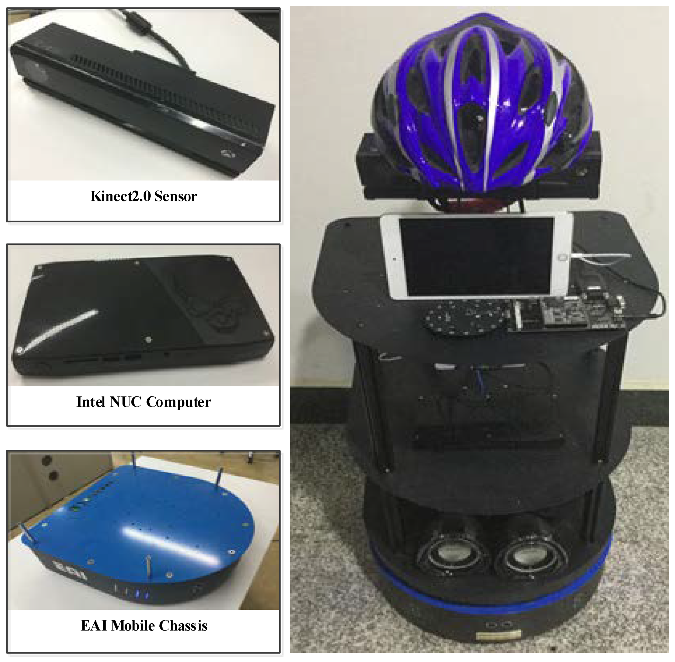
5.1. Platform of the Used Robot
In order to test the performance of the proposed algorithm, we built a social robot platform, the MAT social robot [
33], as shown in
Figure 3. The platform consists of mobile chassis, host computer, sensors, and mechanical bracket, etc. The mobile chassis is the EAI DashGO B1 ((The manufacturer of the equipment is the EnjoyAI company in Shenzhen, China)), which is capable of remote mobile control and provides a 5V-24V independent power interface. The audio sensor is the ring microphone array board (The manufacturer of the equipment is the iFLYTEK company in Hefei, China). The vision sensor is a depth camera Kinect 2.0 with a maximum resolution of 1920*1080 and a transmission frame rate of 30fps. The host computer of the service robot is a Next Unit of Computing (NUC) produced by Intel Corporation, and it has a Core i7-6770HQ processor that has 2.6-3.5GHz frequency, and the graphics processor is the Intel IRIS Pro. Besides, for the host computer, we installed 16 GB of memory with 2133 Mhz frequency.
We implemented the proposed algorithms with C++ programming and integrated the implemented algorithms with the ORB-SLAM2 system to obtain an improved ORB-SLAM2 system. Finally, we installed the improved system in the Ubuntu16.04 system on the MAT social robot’s host computer.
In particular, before the experiments, we performed an intrinsic matrix calibration of the depth camera according to the steps of the official document. Kinect2.0 and Intel NUC were powered by mobile chassis.
5.2. Experimental Design
In order to evaluate the performance of the improved ORB-SLAM2 system, we designed the following experiments:
(1) The impact of different formats’ vocabulary on the system startup speed and scale. Considering that loading the vocabulary is the most time-consuming part of the system startup process when testing the system startup speed, we compared the time it took for the system to read the different formats of the vocabulary.
(2) Performance comparison between small-scale vocabulary based on the algorithm of this paper and original large-scale vocabulary of ORB-SLAM2. The training and test data used in the experiments were from the public RGB-D dataset provided by Technische Universität München (TUM) [
34]:
fr1_room,
fr1_xyz,
fr1_360,
fr2_rpy,
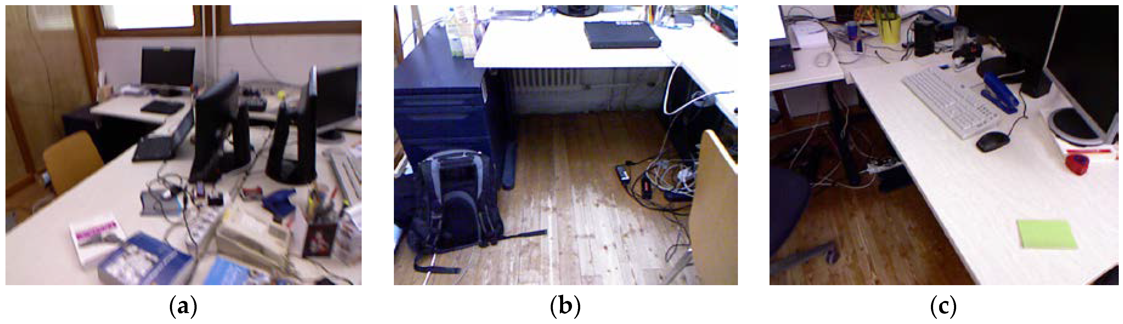
fr2_desk. The reason why we used this database was that every sequence of the TUM database contained the real trajectory file, so we could compare the test results with the real situation. We used the
fr1_room sequence as an input to the vocabulary training algorithm, where the
fr1_room contains 1362 RGB images taken by the Kinect 1.0 depth camera, the image sequence collection environment is a complete indoor office environment, and
Figure 4 is part of the scene. Also, in order to visualize the comparison results, we used the root mean square error (RMSE) of the actual mapping trace and the real trace as a performance comparison metric.
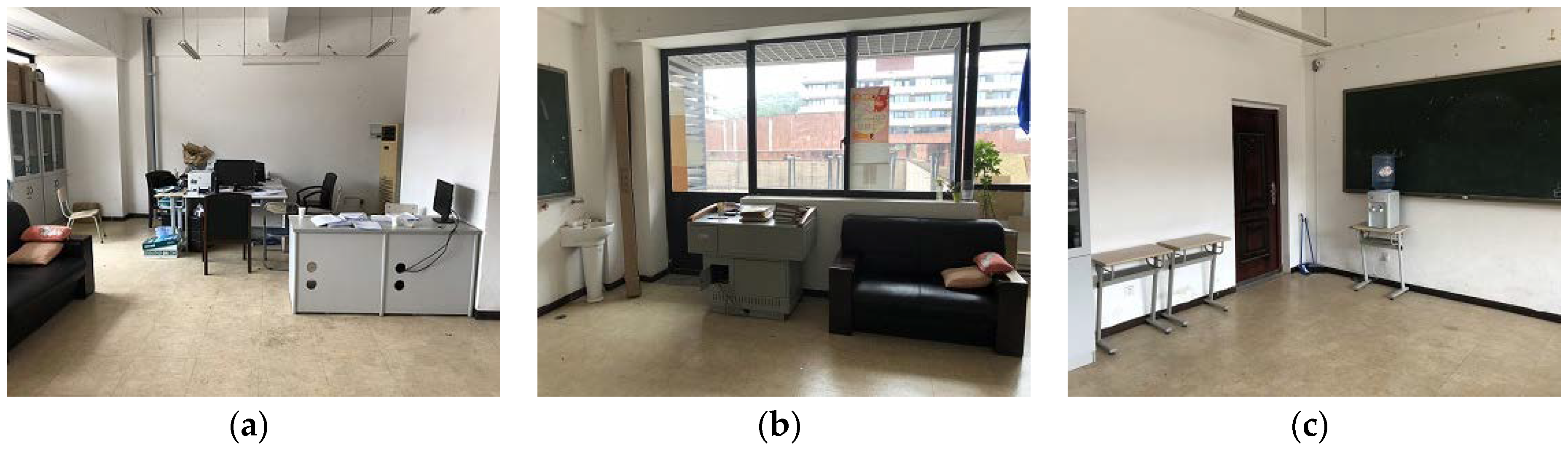
(3) Offline map construction and fast relocation experiments. In the real world, we ran the robot to test whether the system could build an offline map, and whether it could load the offline map to quickly relocate the robot after rebooting. In addition, based on the saved offline map and keyframes file, we will verify that the method in this paper can visualize the map elements and mapping trajectory offline.
In this experiment, the actual test environment we used is shown in
Figure 5. The office is a typical indoor office environment of approximately 43 square meters. The interior includes desks, chairs, computers, printers, etc. The wall is white and contains large transparent glass windows, so there will be a change in the number of feature points extracted and changes in illumination in the tracking process of the system, which will have an impact on the accuracy of localization and mapping. However, in reality, the working environment of mobile robots is usually non-idealized, so our test environment is of practical significance.
(4) Restore mapping experiment. We took into consideration that in actual applications, the working environment of the robot will be dynamic, e.g., chairs will often move. Therefore, in order to test whether the proposed method could adapt to such environmental changes, we designed a restore mapping experiment based on the expected results of Experiment 3. The experimental environment is shown in
Figure 6. This is an empty room with a relatively regular ground marking. The reason for choosing this environment was that it was easy to observe changes in the map. We placed several objects of different shapes and colors on the blackboard to ensure that the system could detect enough feature points. In addition, as seen in
Figure 6b, we set the motion area of the robot to be the light-colored track portion on the ground and kept the robot’s viewing angle unchanged during the motion. These settings are for visual comparison of the actual environment and the map.
In the experiment, we first started the improved ORB-SLAM2 system and controlled the robot to move on the track to complete the construction. After completing the mapping task, we controlled the robot to stop moving to keep the map data stable, and closed the system to construct an offline map. Next, we restarted the system for rapid relocation of the robot, and added an “obstacle” (a person sitting in a chair) to the visible range of the robot to change the original environment, as shown in
Figure 6c. Then, we started the mapping mode in the system’s real-time visual interface, and controlled the robot to continue to move on the track, while observing the real-time changes of the map data.
5.3. Experimental Results Analysis
5.3.1. Optimization Experiment in Binary Format Vocabulary
We converted the original text format vocabulary
TVOC of ORB-SLAM2 to the binary format,
BVOC using the method of this paper, and the size comparison of the two vocabularies is shown in
Table 1. Then, we used two kinds of vocabulary to start the system five times each. Time cost statistics are shown in
Table 2.
The results in
Table 1 show that when the vocabulary is converted to binary format, the volume of the vocabulary is reduced by 69.44%, which is a reduction from 145.3 MB to 44.4 MB, thus greatly saving the space occupied by the vocabulary and helping the system to be lightweight.
The results in
Table 2 show that reading the binary format vocabulary takes an average of 0.43 s, while the text vocabulary has an average reading time of about 8.06 s, which is 18.7 times the time overhead of reading the binary vocabulary.
5.3.2. Small-Scale Vocabulary Performance Test Based on Improved Training Algorithm
We obtained the binary format small-scale vocabulary Fr1VOC using the method of this paper, and compared the performance between Fr1VOC and the original vocabulary BVOC of ORB-SLAM2.
Firstly, we experimented with the training dataset
fr1_room as a test dataset, making the vocabulary training environment exactly the same as the system working environment. Then, we took
Fr1VOC and
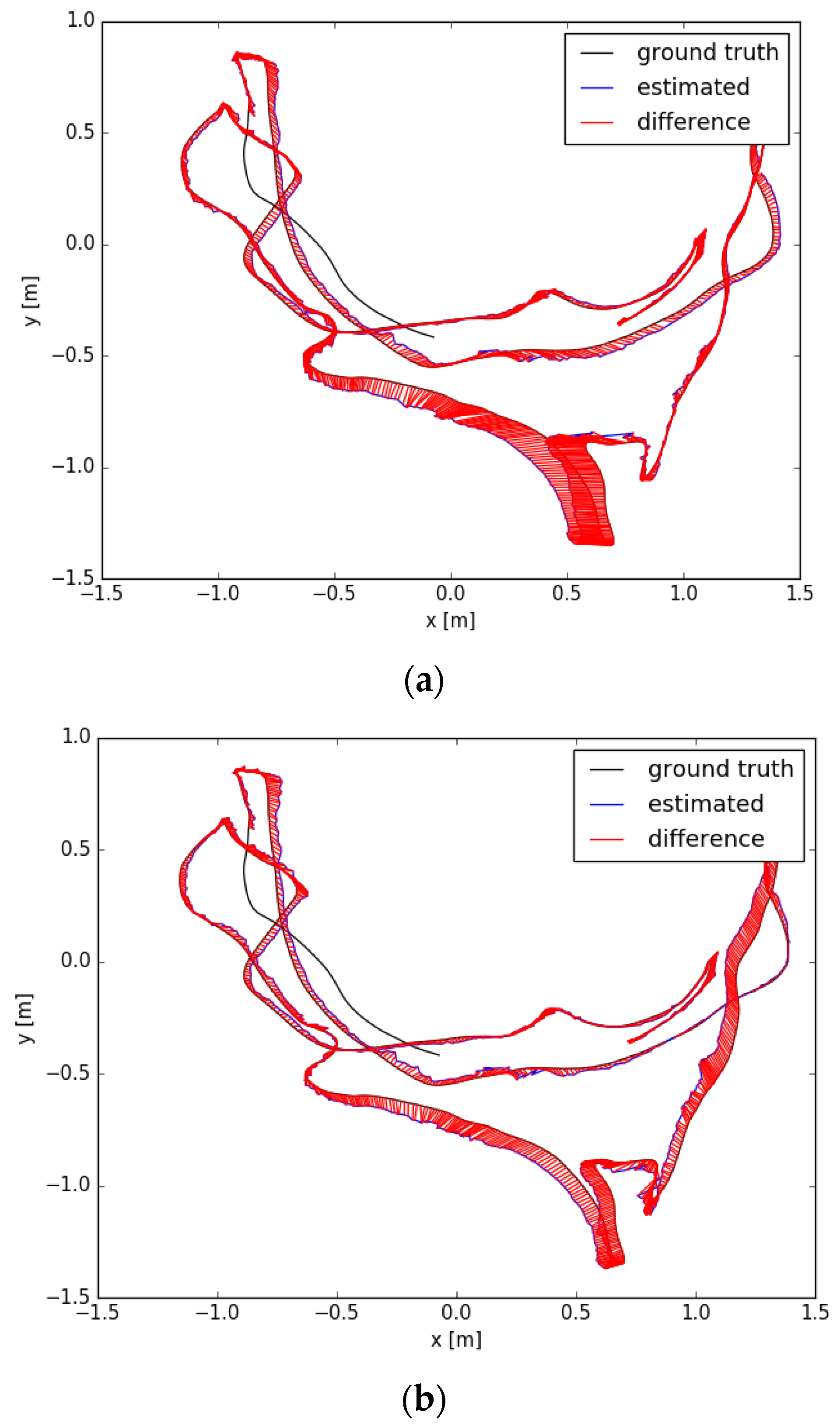
BVOC as inputs, respectively, and started up the ORB-SLAM2 system to localization and mapping, and finally calculated the RMSE value of the actual mapping trajectory and the real trajectory. The comparison between the actual mapping trajectory and the real trajectory is shown in
Figure 5, and
Table 3 compares the size of the two vocabularies and the trajectory RMSE values when using two vocabularies, respectively.
According to
Figure 7, it can be seen that when using the large-scale vocabulary
BVOC to track the
fr1_room dataset, the distance between the actual running trajectory and the real trajectory in most of the road segments is larger than the distance when using the small-scale vocabulary
Fr1VOC. The specific data comparison in
Table 3 verifies our point of view; the trajectory error when using
BVOC is 0.081, while it is 0.049 when using
Fr1VOC, which is a 38.92% reduction; at the same time, the vocabulary volume has been reduced from 44.4MB to 11.9MB, a decrease of 73.2%. The above data and analysis show that in an ideal environment (training the vocabulary using the image dataset of the working environment), the small-scale vocabulary can achieve a large performance improvement for the ORB-SLAM2 system.
Considering the difference in practical applications, we could not collect working environment data for each robot and train the corresponding vocabulary, but different environments can be classified, and each type of environment has the same characteristics. In order to test the performance of the small-scale vocabulary in similar environments (not the same), image sequences
fr1_xyz,
fr1_360,
fr2_rpy, and
fr2_desk were used as test datasets, and then we started up the ORB-SLAM2 system to track and construct a map using
Fr1VOC and
BVOC, respectively, after which we could finally calculate the RMSE values of trajectory errors, where the results are shown in
Table 4.
The data in
Table 4 show that when using the small-scale vocabulary
Fr1VOC, the trajectory errors value for the
fr1_360,
fr2_rpy, and
fr2_desk datasets is slightly reduced by 0.86% to 5.97%, compared to using the
BVOC vocabulary. Only when the test dataset is
fr1_xyz, the trajectory error is slightly increased by 3.9%. The above results show that small-scale vocabulary, based on specific environment training, can improve the running accuracy in most cases when applied to similar environments.
The above experiments and results analysis show that the small-scale vocabulary obtained by training the image of the specific environment based on the algorithm of this paper can improve the running accuracy of the system when working in a specific environment. Moreover, it also eliminates the problem of how the original large-scale vocabulary of ORB-SLAM2 includes a large amount of ineffective data.
5.3.3. The Experiments of Offline Map Construction and Robot Rapid Relocation
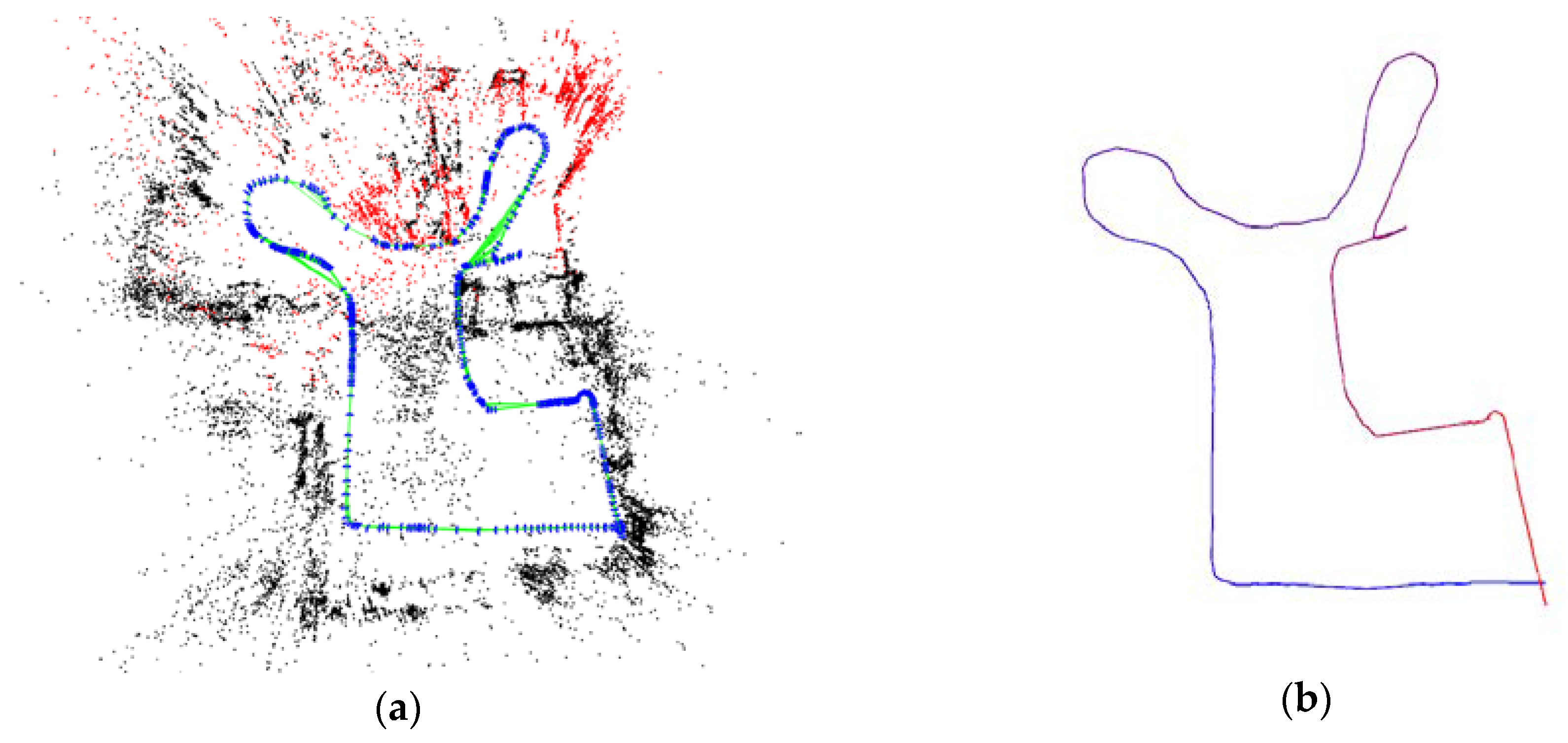
Firstly, we started the ORB-SLAM2 system which implemented the algorithm of this paper, and controlled the Mat Social robot to walk around the test environment to form a trajectory closed loop; then we shut down the system, and used this method to visualize the map and the keyframes trajectory. The results are shown in
Figure 8.
As shown in
Figure 8a, the visualization method of this paper enabled the ORB-SLAM2 system to successfully load the offline map and restore 3D map points and keyframes. The visual map completely expresses the structure of the test environment, and the relative positions of the obstacles are correct. The robot trajectory consisting of keyframes in
Figure 8a is consistent with the trajectory shown in
Figure 8b. The above results show that the ORB-SLAM2 system, based on this method, can construct the offline map and visualize the map and mapping trajectory offline.
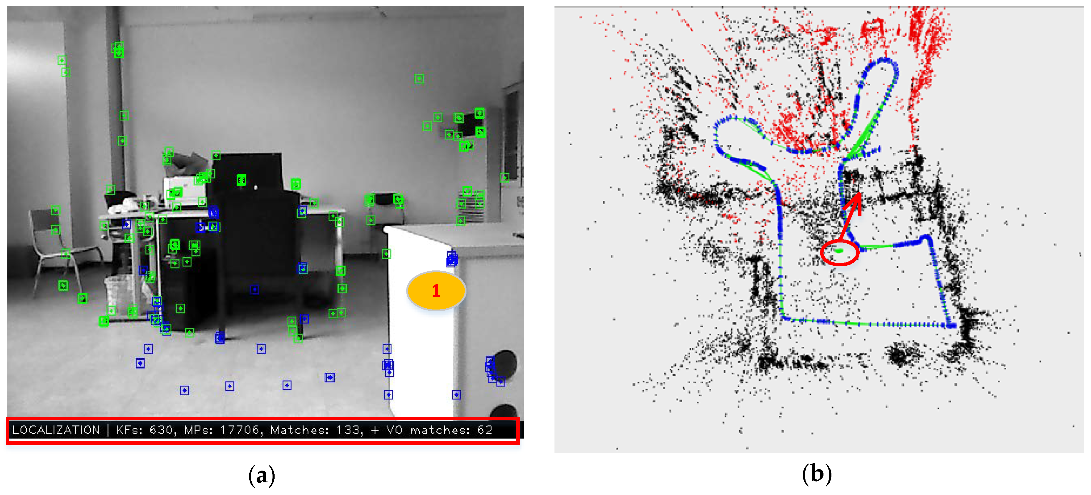
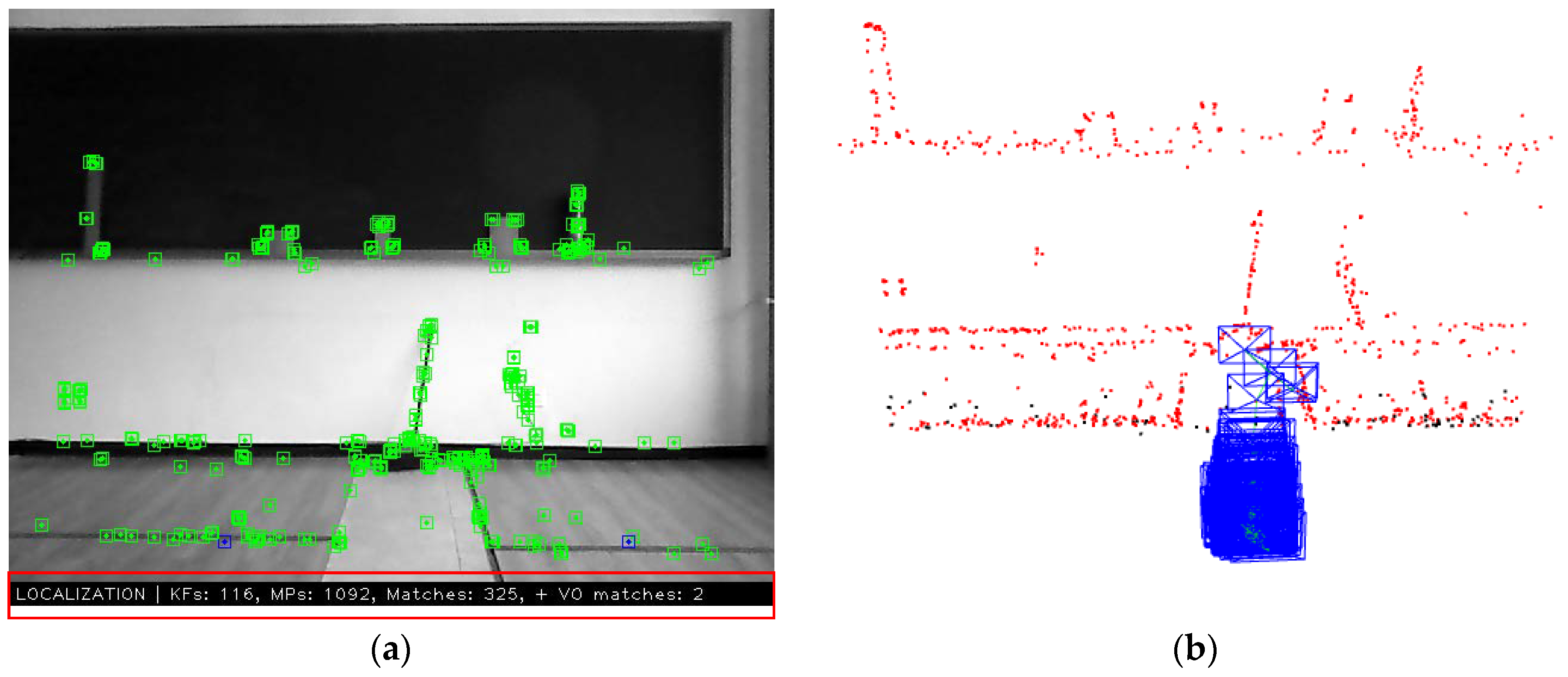
We experimented with the rapid relocation of the robot based on the saved offline map. Considering that large independent obstacles are easily distinguishable in the point-cloud map, in order to distinguish the relocation result of the robot, we first controlled the robot to leave the mapping trajectory and stay near a separate desk. Then we started the ORB-SLAM2 system through the data of a real-time visualization window, checked whether the system had loaded the offline map data, and confirmed the robot relocation effect. The result is shown in
Figure 9.
According to the keyframe, map point, and feature-matching data in the red box below
Figure 9a and the complete point-cloud map shown in
Figure 9b, it can be explained that the offline map data has been fully loaded and restored correctly. Firstly, we infer the position of the robot in the point-cloud map based on the RGB in
Figure 9a. The robot is facing the office area, and the area marked 1 on the right front is the stand-alone desk mentioned above, which we recorded as
desk 1. Since the robot is close to
desk 1, it needs to be bypassed when building the map, meaning the location of the robot should be close to the corner of the mapping trajectory.
Figure 9b shows the map’s real-time visualization interface of the ORB-SLAM2 system, where the green image block in the red elliptical circle represents the robot, and the location of the robot is near the corner of the construction trajectory. At the right front of the robot is the position of
desk 1 in the map. This verified our judgment of the location of the robot based on the information in
Figure 9a. The above test results and analysis show that the method of this paper can make the robot achieve rapid relocation.
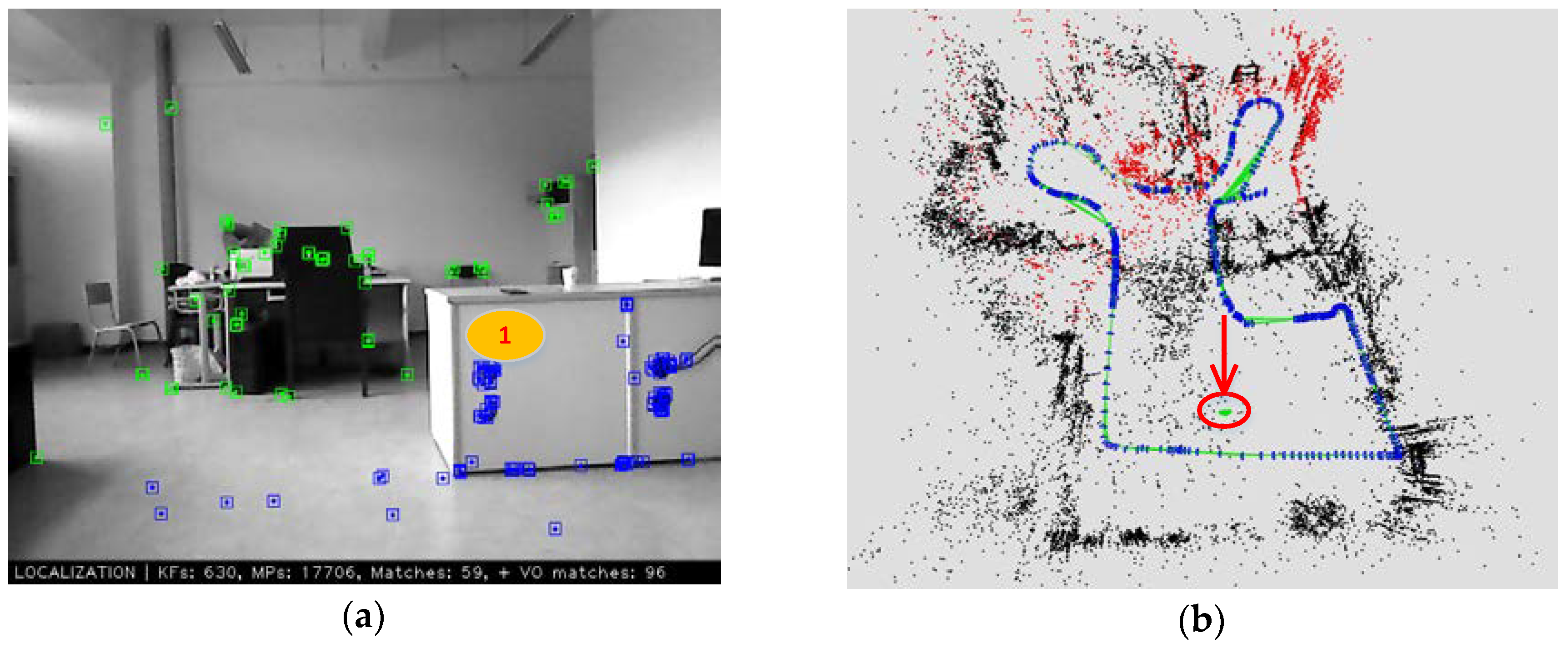
We tested whether the system could restore global tracking after the robot relocated correctly. Firstly, we controlled the robot to retreat a distance without changing the direction, and then observed the tracking state of the robot in the map. The results are shown in
Figure 10.
Figure 10 shows the real-time visual interface of the ORB-SLAM2 system after the robot has moved a distance. Comparing
Figure 10a with
Figure 9a, the movement of the robot follows the experimental design: moving backward without changing the direction. Although we cannot accurately judge the moving distance of the robot based on the image, it can be determined that the robot location should be close to the mapping trajectory behind it. As shown by the red arrow in
Figure 10b, the position of the robot has changed, moving from the original position to the rear and nearing the mapping trajectory below the map, and this is consistent with the actual movement of the robot.
The above experimental results and analysis show that the proposed method can make the robot relocate quickly and restore global location and tracking. This avoids repeated mapping, saving computational resources for the robot and improving work efficiency.
5.3.4. Restore-Mapping Experiment
Firstly, we controlled the robot to move onto the orbit and built the map according to the experimental design, and then reproduced the map scene with the offline visualization method proposed in this paper. The results are shown in
Figure 2.
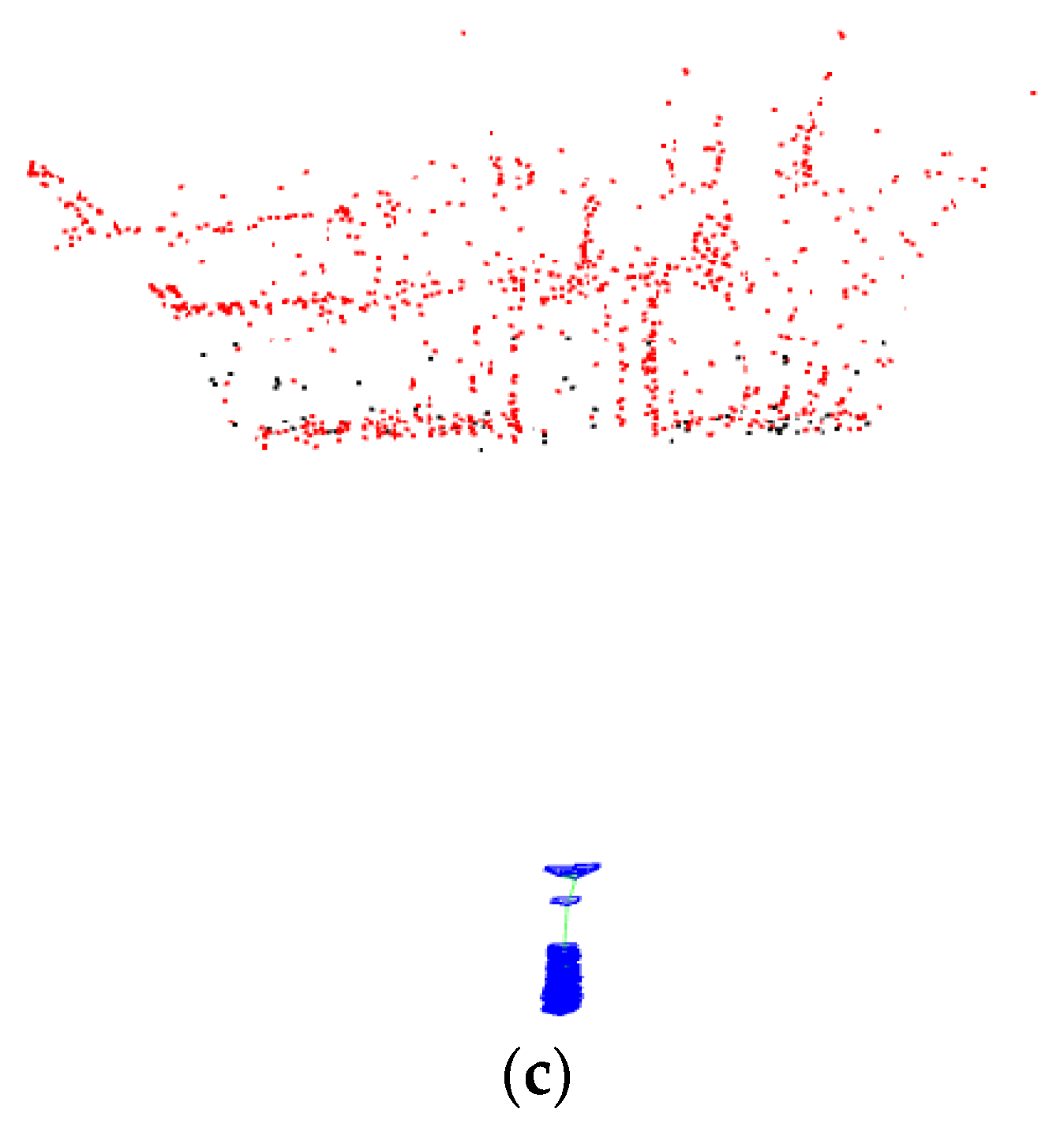
Figure 11 shows the map status after the mapping is completed. Among them,
Figure 11a shows the real-time RGB image of the system, and the figure shows that the number of feature points is sufficient. At the bottom of
Figure 11a, we marked the map element data with a red box, in which the number of keyframes was 116 and the number of map points was 1092.
Figure 11b is the sparse map with the same angle-of-view as
Figure 11a. Compared with the actual environment, the environmental structure of the map is correct and clear.
Figure 11c is a map with an overlooking angle, and we can find that the map points are mainly concentrated in the part close to the wall. There is some blank space between the point-cloud concentration region and the position of the robot. This result is what we expected because it helps us to use this blank area for subsequent experiments, and we can directly observe changes in the map without interference from other point-cloud distributions.
After the completion of the above experiment, we changed the environment and then performed the test of restore mapping according to the experimental design. The results are shown in
Figure 12.
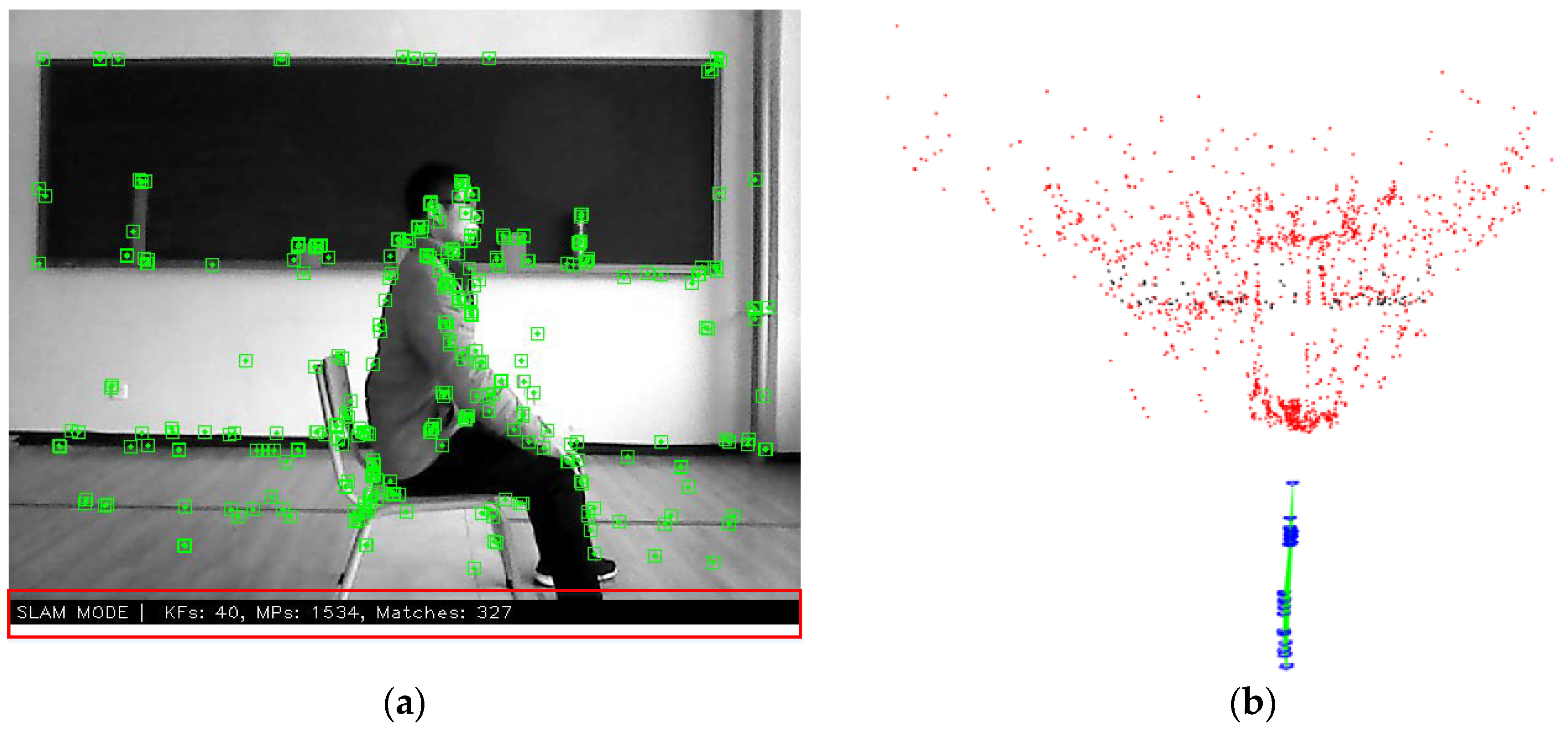
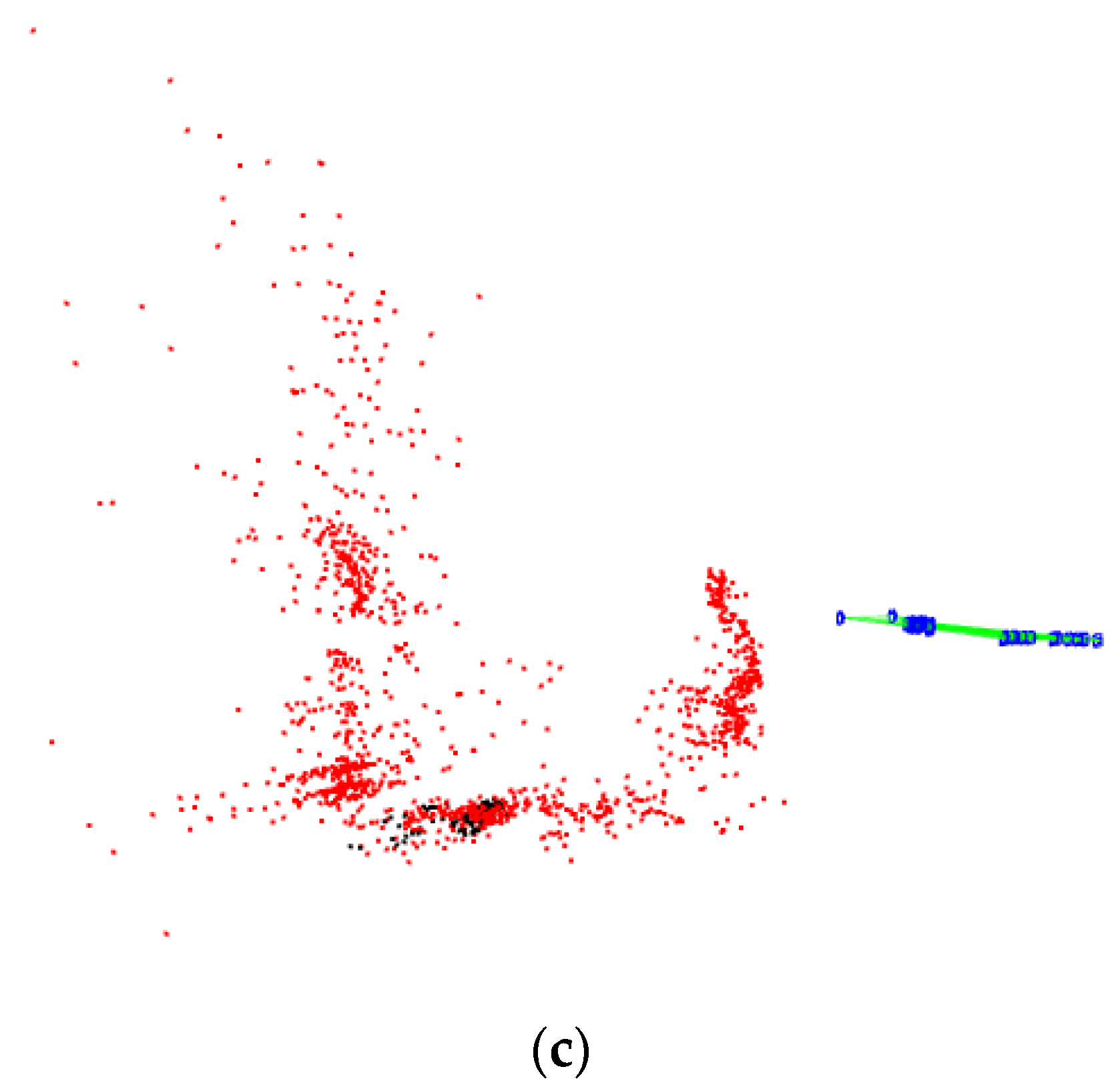
Figure 12 shows the restore mapping status after the environment change.
Figure 12a is an RGB frame during mapping, and the image shows that the system has detected the newly added features of the person and the chair. The element data of the map marked by the red box at the bottom of the image has changed significantly. The number of map points continues to increase, but the number of key frames dropped sharply, which is because the environment has changed and the system is continuously updating keyframes.
Figure 11b,c are the top view and side view of the map after completion of the construction, respectively. The image shows that some new map points were added in the blank area in
Figure 11c that are consistent with the environmental changes, and the outline of the person sitting on the chair (near the side of the camera) can be found in the side view. In addition, in contrast to
Figure 11c, the new mapping trajectory also changed according to the movement of the robot.
The analysis of the above experimental results shows that the method proposed in this paper can continue to construct the changing part of the environment after a change in the environment, so as to be applicable to the new environmental structure. In other words, the method proposed in this paper has strong robustness against changes to the environment.
6. Discussion and Conclusions
This paper proposed an improved ORB-SLAM2 system for improving the problems of the original system in terms of startup speed, tracking accuracy, and map reuse. Firstly, we proposed a binary-based vocabulary storage method to improve the startup speed of the ORB-SLAM2 system. Then, we proposed an improved vocabulary training algorithm to train small-scale vocabularies for specific environments for improving system location accuracy. Finally, we proposed the offline map construction method and the rapid relocation method of a robot, which enables the system to quickly restore the location tracking state based on an offline map, avoiding repeated mapping and changing the working mode of the original ORB-SLAM2 system. In addition, when the environment changes, the improved system is able to restore mapping to reconstruct the changing part of the environment. Through experiments and results analysis, we proved that the method proposed in this paper could achieve the expected goal, and the improved ORB-SLAM2 system can be better applied to mobile robots. However, the proposed methods in this paper also have limitations. Firstly, since we do not have much related research, the improved system cannot provide a dense point-cloud map. In addition, our Binary-based Vocabulary Storage method can provide a binary vocabulary for the system, but from the perspective of readability, this is not very user-friendly; thus, if researchers need to read vocabulary information directly, our method may not be applicable.
In future studies, we will focus on the rapid dense map construction of the visual SLAM and the semantic SLAM. We hope to promote the diversification of the functionality of the visual SLAM to match the complex task requirements of the intelligent mobile robot.


