Article

New Perspectives in Landslide Displacement Detection Using Sentinel-1 Datasets

1
Italian National Research Council (CNR), Research Institute for Geo-Hydrological Protection (IRPI), Corso Stati Uniti 4, 35127 Padova, Italy
2
Department of Civil, Chemical, Environmental and Materials Engineering DICAM, Alma Mater Studiorum Università di Bologna, Viale Risorgimento 2, 40136 Bologna, Italy
*
Author to whom correspondence should be addressed.
Remote Sens. 2019, 11(18), 2135; https://doi.org/10.3390/rs11182135
Submission received: 26 June 2019 / Revised: 9 September 2019 / Accepted: 11 September 2019 / Published: 13 September 2019
(This article belongs to the Section Remote Sensing in Geology, Geomorphology and Hydrology)

Abstract

:
Space-borne radar interferometry is a fundamental tool to detect and measure a variety of ground surface deformations, either human induced or originated by natural processes. Latest development of radar remote sensing imaging techniques and the increasing number of space missions, specifically designed for interferometry analyses, led to the development of new and more effective approaches, commonly referred to as Advanced DInSAR (A-DInSAR) or Time Series Radar Interferometry (TS-InSAR). Nevertheless, even if these methods were proved to be suitable for the study of a large majority of ground surface dynamic phenomena, their application to landslides detection is still problematic. One of the main limiting factors is related to the rate of displacement of the unstable slopes: landslides evolving too fast decorrelate the radar signal making the interferometric phase useless. This is the reason why A-DInSAR techniques have been successfully applied exclusively to measure very slow landslides (few centimetres per year). This study demonstrates how the C-band data collected since 2014 by the Sentinel-1 (S1) mission and properly designed interferometric approaches can pull down this restriction allowing to measure rate of displacements ten times higher than previously done, thus providing new perspectives in landslides detection. The analysis was carried out on a test site located in the Cortina d’Ampezzo valley (Eastern Italian Alps), which is affected by several earth flows characterized by different size and kinematics.

Graphical Abstract

1. Introduction

The application of imaging radar remote sensing to geosciences is nowadays a fast moving field. Since the launch of Seasat in 1978, the first Earth-orbiting satellite equipped with a Synthetic Aperture Radar (SAR), numerous space missions have followed. The developments of radar remote sensing led to the study of ground surface dynamic phenomena and in 1993, Massonet [1] reported the first successful application of space-borne differential interferometic SAR (DInSAR) to map the co-seismic deformation of the Landers earthquake. In recent times, DInSAR has experienced a continuous growth mainly related to the increased number of missions specifically designed for interferometric analyses and the large amount of acquisitions collected through the years that have favored the generation of a wide number of data processing methods and analysis tools e.g., [2,3]. These techniques, commonly referred to as Advanced DInSAR (A-DInSAR) or Time Series Radar Interferometry (TS-InSAR) are similar implementations of two main approaches: the Persistent Scatterer Interferometry (PSI) [4], based on the identification of natural point-like targets in stacks of interferograms, and the Small Baseline Subsets (SBAS) [5], centered on the privileged spatial and temporal relations of the acquisitions. A-DInSAR offers the possibility to map and measure small ground displacements over large temporal and spatial scales with sub-centimetre accuracy, combining the high precision of classical geodetic surveys with the imaging property of remote sensing techniques. These approaches have been successfully applied to monitor ground deformations of different origins, both natural and anthropic e.g., [1,6,7,8]. Nevertheless, the practical applicability of A-DInSAR analysis to study landslides is still problematic since it is inherently related to the size, the aspect and the inclination of the slope, to land cover and to the velocity and mechanisms of displacement [9]. The Sentinel-1 (S1) mission, developed and operated by the European Space Agency (ESA), is implemented through a constellation of two satellites (A and B units), launched in 2014 and 2016, respectively. S1 satellites were designed to provide the scientific community with data continuity after the operational end of ERS and ENVISAT missions with enhanced temporal and spatial resolution, along with small orbital baselines. These characteristics certainly favor the application of A-DInSAR analysis to landslides by loosening two major bonds such as the small dimensions and, occasionally, the high velocity of the mass movements.
According to Cruden and Varnes [10], landslides can be grouped in seven classes depending on their rate of displacement (Table 1).
So far, A-DInSAR analyses have proven to be effective in the detection and measurement of landslide classified as very slow (few centimeters per year) [11,12,13,14,15,16]. This study demonstrates that processing data collected by the S1 mission, with properly designed interferometric approaches, can extend the field of application to the upper class of slow landslides (few metres per year), thus providing new perspectives in landslides detection. The analysis was carried out on the test site of Cortina d’Ampezzo, a town located in a wide valley in the hearth of the Dolomites (Italian Eastern Alps), on whose surrounding slopes more than 30 landslides, differing in type, size, state and stile of activity and rate of displacement have been identified and mapped [17]. The analysis focused on the landslides affecting large portions of the western slope of the Cortina d’Ampezzo valley. Mass movements different in size and rate of displacement by an order of magnitude have been discriminated, mapped and measured, establishing new boundaries for the application of radar remote sensing to landslides hazard assessment.

2. Study Area

The Dolomites are a mountainous group of the Italian Eastern Alps, numbering 18 peaks above 3000 metres a.s.l. and covering an area of 231,000 hectares. Known for their stunning beauty, featuring spectacular landscapes with one of the best examples of the preservation of Mesozoic carbonate platform systems, the Dolomites were listed as a UNESCO World Heritage Site in 2009. The town of Cortina is located in the Ampezzo Valley, crossed by the Boite River and surrounded by the grandeur of the dolomitic peaks (Figure 1). The town is certainly one of the most known and fashionable touristic resort of the Dolomites. Cortina hosted the Winter Olympics game in 1956 and, after that a number of international winter sports events. Recently, it has obtained the assignment of the Alpine Ski World Championships, scheduled in 2021 and the 2026 Winter Olympics. The impressive location of Cortina d’Ampezzo, its glamorous legacy as a tourist destination at any time of the year and the natural predisposition at hosting relevant sports events, led to a constant growth of the anthropic pressure and hence the vulnerability in a valley, known to be intensely affected by geo-hydrological hazards.
Since the retreat of the Würmian glaciers, some 11,000 years ago, the Ampezzo valley was largely interested by mass movements [17]. The renewals of these extensive and ancient landslides continuously endanger and in some cases damage houses, roads and skiing facilities. The proneness of the Ampezzo valley to instability phenomena can be attributed to several factors [18,19,20]. First of all, the structural conditions of the area have to be considered. The stratigraphical sequence consists in an alternation of dolomitic rocks and clayey geological formations. The presence of lithotypes with different geomechanical properties represent a predisposing factor wherever the rigid and resistant rocks with a brittle behavior overlie the plastic rocks characterized by a ductile deformation. Another important factor derives from the effects of tectonics. Folds and faults stressed and dismembered the rock masses that became much weaker and prone to erosion. Finally, the glacio-pressure effect [19] has to be considered. It is likely that the pressure of ice on the valley sides during the Würmian glaciation determined rock deformations in correspondence with surfaces of structural discontinuity, favoring the formation of potential sliding surfaces. The glacial debuttressing, permafrost melting and high relief energy have then favored the occurrence of slope instability processes [21,22,23].
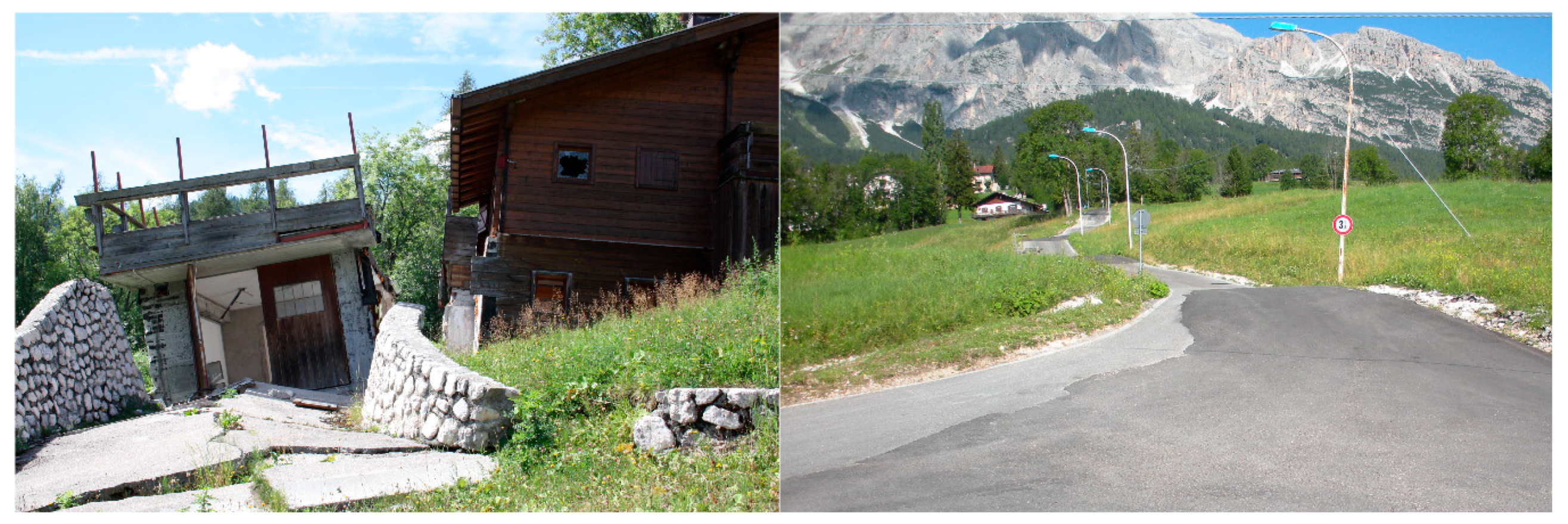
The characteristics of the landslides generally depend on the lithological and structural conditions: where the dolomitic rock outcrops, in the highest part of the valley, rock falls occur, while slides and flows are frequent in the medium and lower sectors of the slopes in correspondence of the marly and clayey formations [20,24]. On the western slope of the valley, the earth flow (or mudslide according to the British usage), known as Lacedel landslide, was presumably triggered in the Late Glacial and is characterized by a recurrent activity that continues to date. The mass movement extends for an approximate length of 3.5 km, from the crown located at 1750 m a.s.l. to the toe, in correspondence to the Boite river bed at 1150 m a.s.l. Subsurface investigations estimated the thickness of the landslide between 40 and 60 m, most of which was accumulated in the early postglacial [20]. The landslide body is composed by an alternation of silty clays, originated by the weathering of the claystone bedrock and interdigitated dolomitic gravel lenses deriving from Late Glacial debris flow events [25]. A partial reactivation of the earth flow, named Rio Roncatto, is at present the most active sector of the western valley slope. Damaged and abandoned buildings and disrupted roads witness the power release of this landslide (Figure 2).
Recent GNSS (Global Navigation Satellite System) surveys assessed the rate of displacement of the Rio Roncatto landslide body to about 1 m per year, while for the Lacedel landslide the measured deformations are much lower, ranging from in few millimetres per year to several centimetres [26]. However, these measurements are point-based and do not allow to extend their information without incorporating some uncertainty in a bi-dimensional space, specifically a map. Therefore, the definition of the contours of the landslide characterized by different levels of activity, at the time being, must necessary rely also on the qualitative information represented by the geomorphological analysis.

3. Materials and Methods

S1 satellites are equipped with an active phased array antenna that supports four imaging modes characterized by different resolution and coverage: Interferometric Wide Swath (IW), Extra Wide Swath (EW), StripMap (SM), and Wave (WV). Both the IW and EW mode are implemented as TOPS (Terrain Observation with Progressive Scans in azimuth) modes to provide large swath width with enhanced image performance [27]. The main characteristics of S1 mission, instrumentation and products are resumed in Table 2.
S1 datasets are accessible under free, full and open data policy via Copernicus services (https://sentinel.esa.int/web/sentinel/sentinel-data-access). The interferometric analyses were carried out processing 104 S1 images in IW mode along the ascending track n. 44, from the end of October 2014 until late November 2018. Wintertime acquisitions (from December to March) were discarded due to the likely presence of snow that would have increased signal noise. The images were multi-looked by a factor 10 in range and 2 in azimuth direction in order to reduce the speckle noise. This procedure increased the pixel spacing to 23.2 m and to 27.8 m respectively. The datasets were co-registered to a single image acquired on the 17th of July 2017. Even if the S1 orbital parameters are very reliable and despite the fact that the deviations are maintained within a tube of +/- 50 m radius (RMS) [27], precision state vectors, downloaded from the European Space Agency (ESA) Quality Control website (https://qc.sentinel1.eo.esa.int/aux_poeorb/), were used to guarantee highly accurate results. IW images are composed by 3 swaths made of bursts which are affected by large Doppler centroid variations as a consequence of the implementation of the TOPS acquisition mode. The resulting steep azimuth spectrum ramp within each burst requires misregistration errors smaller than 5/1000 of sample in order to avoid residual interferometric phase jumps [28]. As a consequence, a stringent co-registration procedure is obliged. To achieve this task, an iterative procedure was used. A lookup table that permits to resample the data among the master and the slave geometries was derived by exploiting the Shuttle Radar Topography Mission (SRTM) DEM sampled at 3 arc-seconds [29]. After the resampling, the offsets among the images were determined through a matching procedure that uses iteratively cross correlation optimization to reduce mis-registration errors to about 1/100 of sample. Afterwards, a spectral diversity method, which considers the double difference phase in the bursts overlap regions, was applied. The double differences interferograms were multi-looked and unwrapped. The algorithm contemplates only overlap regions with a minimal coverage of high coherence pixels (e.g., 0.8) and the statistics of the unwrapped phases to avoid errors. The accepted values were then combined using a weighted averaging. The offset parameter file is updated, the slave images are resampled and the spectral diversity method applied once again. The procedure was iterated until the mis-registration errors result smaller than 5/1000 of sample. Afterwards, for each burst, the azimuth phase ramp of the master acquisition was calculated, subtracted and then used to deramp the co-registered slave images. The stack of the 104 co-registered and deramped images was then resized to a square of 600 x 600 pixels, covering area of interest for an extension of more than 230 km2. At this stage, two different interferometric procedures were implemented in order to detect both the Lacedel and Rio Roncatto landslides, whose displacement rates differ considerably. The investigation of the former was carried on using an A-DInSAR approach known as Interferometric Point Target Analysis (IPTA) [30] while, for the latter, standard differential interferometric approaches were applied.

3.1. Interferometric Point Target Analysis

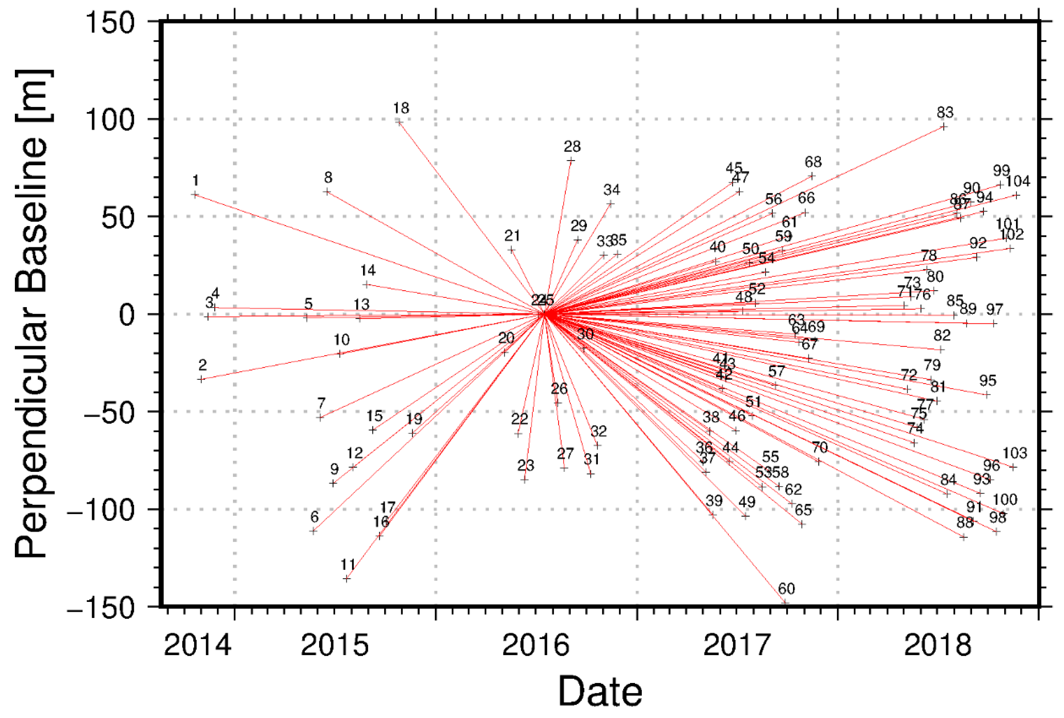
IPTA technique exploits the temporal and spatial characteristics of interferometric signatures back-scattered by natural point-like targets to assess their displacements histories [30]. Point target candidates were selected using two approaches. The first one is based on the spectral properties of prevalent targets within each individual image. Spectral characteristics were averaged over the set of images and targets that show low spectral phase diversity were selected as point target candidates (PTC). The second one is based on the very likely assumption that dominant targets have a lower temporal variability throughout the acquisitions stack compared to distributed scatterers. PTC were hence selected by fixing a threshold to the ratio between the temporal average of backscattering and its standard deviation. Every image in the stack was processed along with the master to generate 103 interferograms with an average perpendicular baseline of 23 m and a maximum temporal baseline of 858 days (Figure 3).
Afterwards, the interferometric phase at each PTC position was flattened by subtraction with the unwrapped synthetic phase derived from the SRTM DEM. The resulting differential interferometric phases between pairs of PTC were analyzed by means of a two-dimensional regression that accounts for the perpendicular baseline and the time elapsed between the interferometric pairs. The parameters resulting from the regression such as the height corrections, the deformation rate, the baseline refinement, the atmospheric phase term and the extension of the PT (Point Target) list, were iteratively improved until the phase model resulted satisfactory.

3.2. DInSAR Analysis

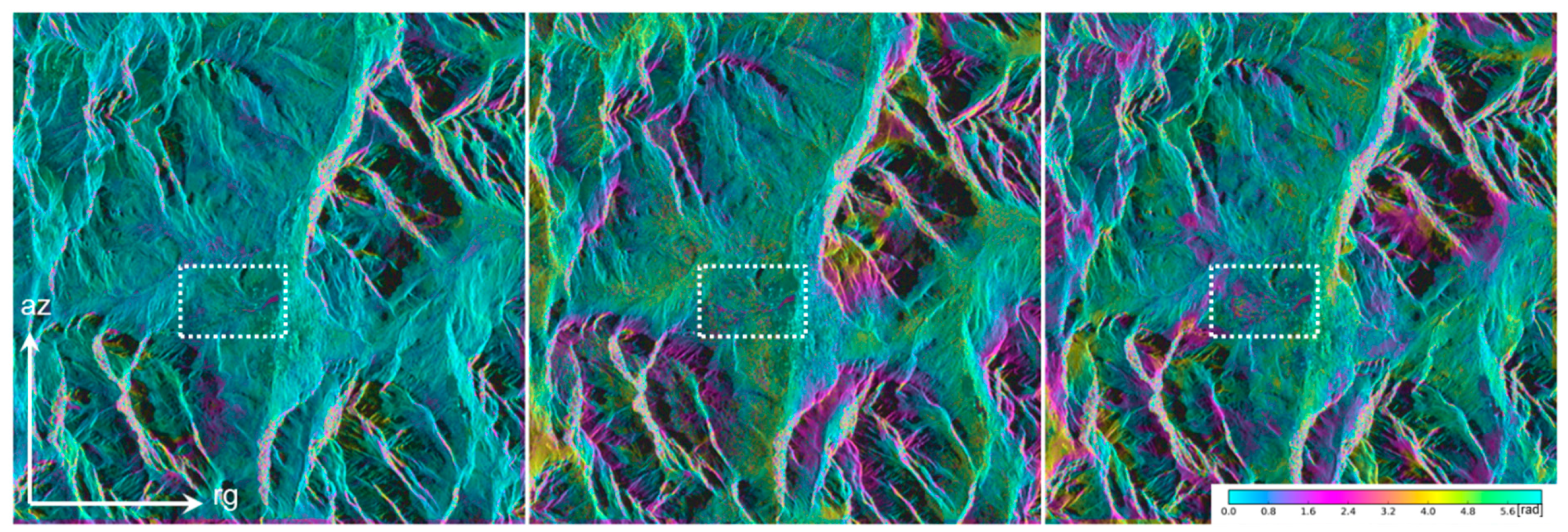
To detect and isolate fringes compatible with the surface displacements of the Rio Roncatto earth flow, a multi-baseline approach was applied. By setting a maximum temporal baseline equal or minor to 24 days, 508 differential interferograms were generated. In several highly coherent phase images a deformation pattern attributable to the mass movement was clearly visible even if the noise and the atmospheric phase screen contribution made it often difficult to discriminate the signal (Figure 4).
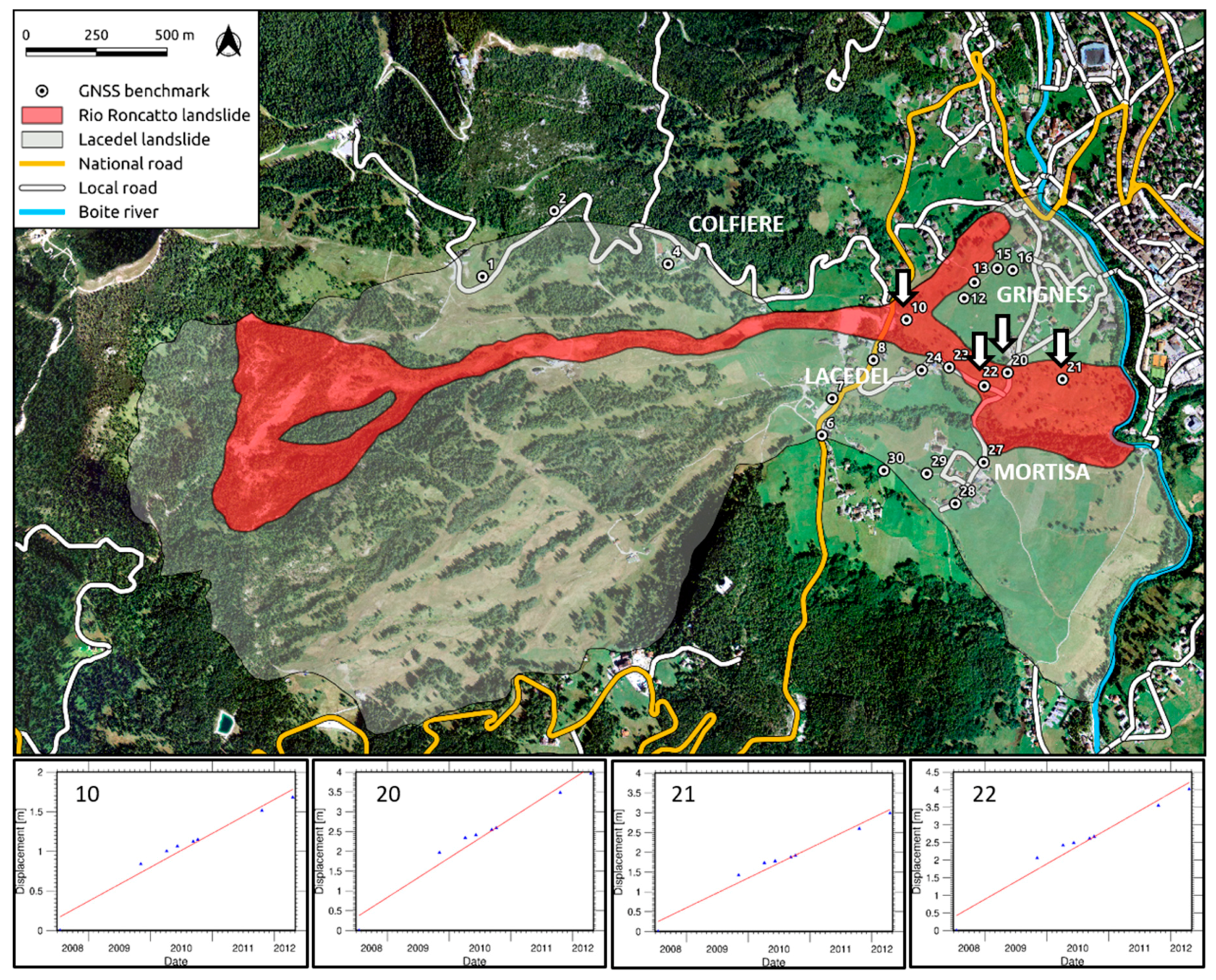
In order to map the Rio Roncatto landslide and measure its rate of movement, an interferometric approach based on two very likely assumptions was designed. Firstly, we assumed the stability of the area surrounding the Rio Roncatto landslide and specifically the Cortina d’Ampezzo urban area and the remaining portion of the western slope (by inspection of the IPTA results, considering a maximum temporal baseline of 24 days, the rate of deformation of the latter can be considered negligible). Under this assumption, we masked the Rio Roncatto landslide and applied a spatial filtering and an interpolation of the interferometric phases over the “stable” areas. The result was interpreted as atmospheric disturbances and subtracted from the differential interferogram. The filtered and flattened complex valued interferograms were unwrapped using a minimum cost flow algorithm [31] and visually inspected to assess the presence of phase errors. The second assumption was that the rate of deformation of the earth flow can be considered constant as demonstrated by the GNSS (Global Navigation Satellite System) surveys operated by Bossi et al. (2016) [26]. Between July 2008 and April 2012, eight fast static relative measurements were carried out. The inferred rate of displacements for the four benchmarks installed over the Rio Roncatto landslide were assessed between 1 and 2 m per year (Figure 5).
Due to temporal decorrelation, interferograms generated from a short time intervals image pairs are generally more coherent. In other words, it is likely that the phase unwrapping would results more reliable and correct for 6-day interval interferograms rather than 12, 18 or 24. Based on this assumption, we added the unwrapped phases of the 6-day interferograms to create phase models for 12 or more days. The complex valued interferograms generated from images with a temporal baseline longer than 6 days were unwrapped using an algorithm forcing the phase of each pixel to the value in the (-π, π) interval of the model. After completion of the unwrapping, a phase constant was subtracted from all unwrapped phase values such that the deformation phase at the indicated stable reference location (the same used in the IPTA processing) would equal 0. The linear rate of differential phase backscattered was estimated from the Rio Roncatto landslide from a stack of six unwrapped differential interferograms. The reference image, acquired on September 22, 2017, was processed along with the 6 subsequent images taken 6 days apart from each other. Phase rate estimation was obtained by weighting the individual interferogram phases for the time interval under the assumption that atmospheric statistics were stationary for the stack of interferograms, according to the following equations:
p h r a t e = j = 1 N Δ t j ϕ j j = 1 N Δ t j 2
v a r ( p h r a t e ) j = 1 N ( ϕ j 4 π λ p h r a t e Δ t j ) 2 Δ t j 2
Where:
  • phrate is the phase linear rate,
  • var(phrate) is the variance of phase linear rate,
  • N is the number of interferograms (in this case 6),
  • t is the time interval,
  • ϕ is the differential interferometric phase,
  • λ is the signal wavelength.

4. Results

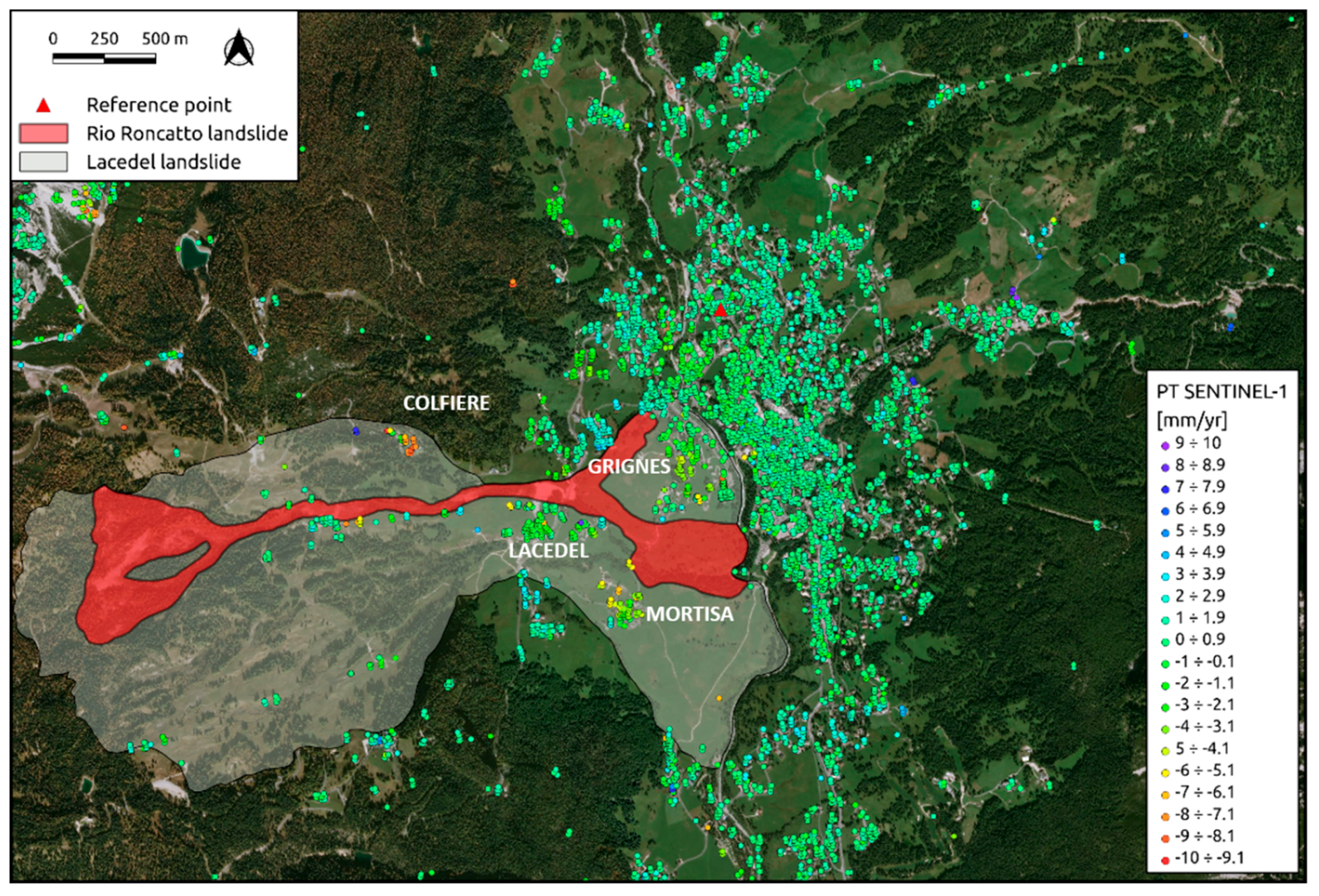
The outcomes of the IPTA processing are reported in Figure 6. Patterns of ground displacements driven by the Lacedel landslide on the western slope of the Cortina d’Ampezzo valley are clearly visible in correspondence of the PT located in the hamlets of Colfiere, Lacedel, Mortisa and Grignes. The town of Cortina d’Ampezzo, at the bottom of the valley, results to be stable, as expected. The majority of the PT are detected in correspondence of built-up areas, ski lifts pylons and a few rock blocks in the upper part of the slope. No displacement information can be inferred over the body of the Rio Roncatto landslide. The maximum displacement rate calculated at PT location varies from 10 (Colfiere) to 6 mm/yr (Lacedel).
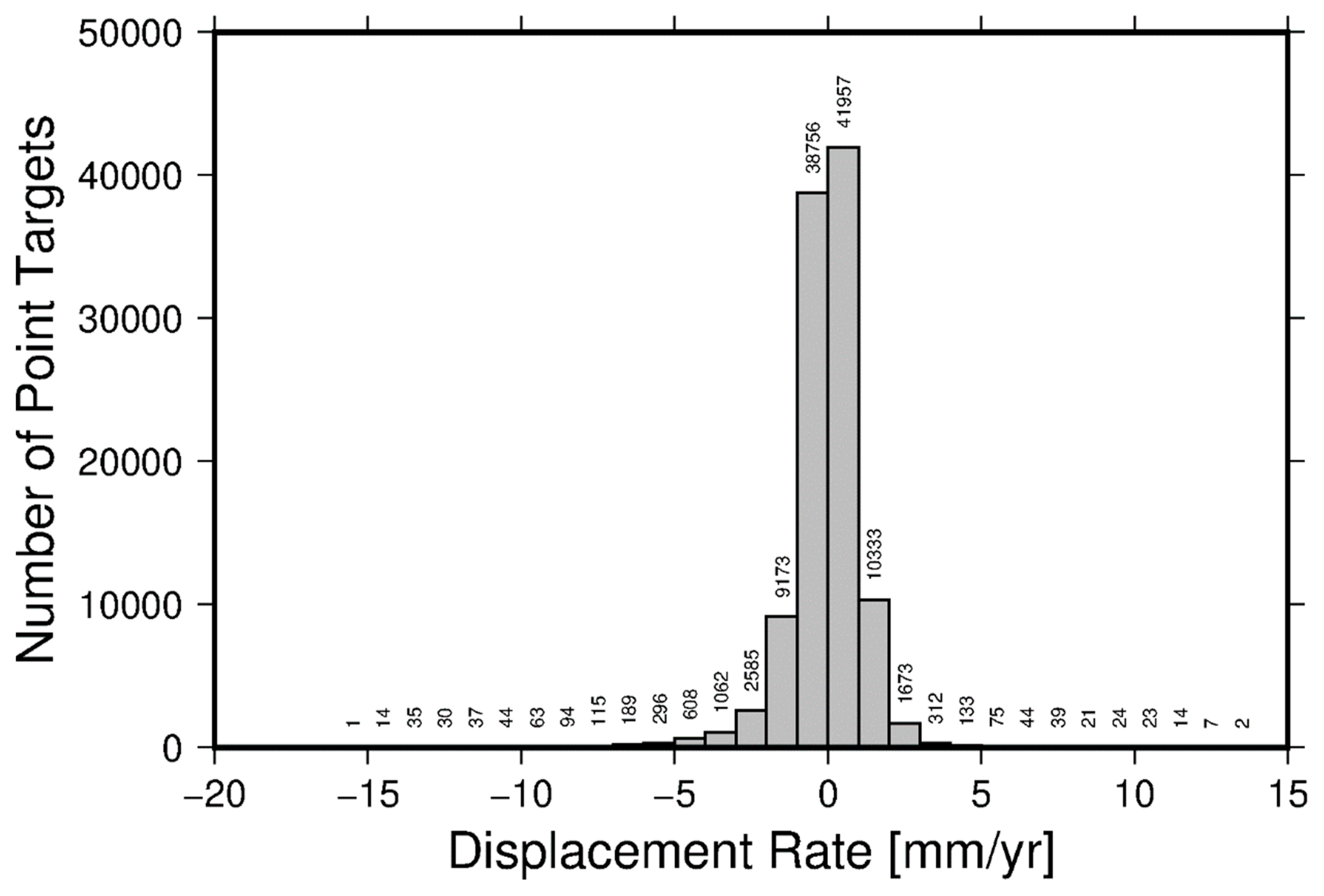
A quantitative assessment of the IPTA analysis outcomes can be inferred from the histogram in Figure 7. PT have been grouped in displacement rate classes with a bin-width of 1 mm/yr. Negative values of the velocity witness an increasing distance between the sensor and the ground target throughout time. It can be noticed that the data arrange as a normal distribution slightly skewed to the left, towards negative values. The large majority of the PT are grouped around the null value of the rate of displacement and reflects the kinematics behavior of the radar target located in the town of Cortina d’Ampezzo. Negative values are related to the mass movements affecting the western slope of the valley (i.e. Lacedel landslide). On the contrary, the majority of the PT spread on the right side of the histogram can be attributable to the eastern slope instabilities. The positive values of the rate of deformations are recoded by targets moving toward the sensor and are hence suitable considering the ascending geometry of acquisition of the processed dataset and the prevalent direction of the displacements.
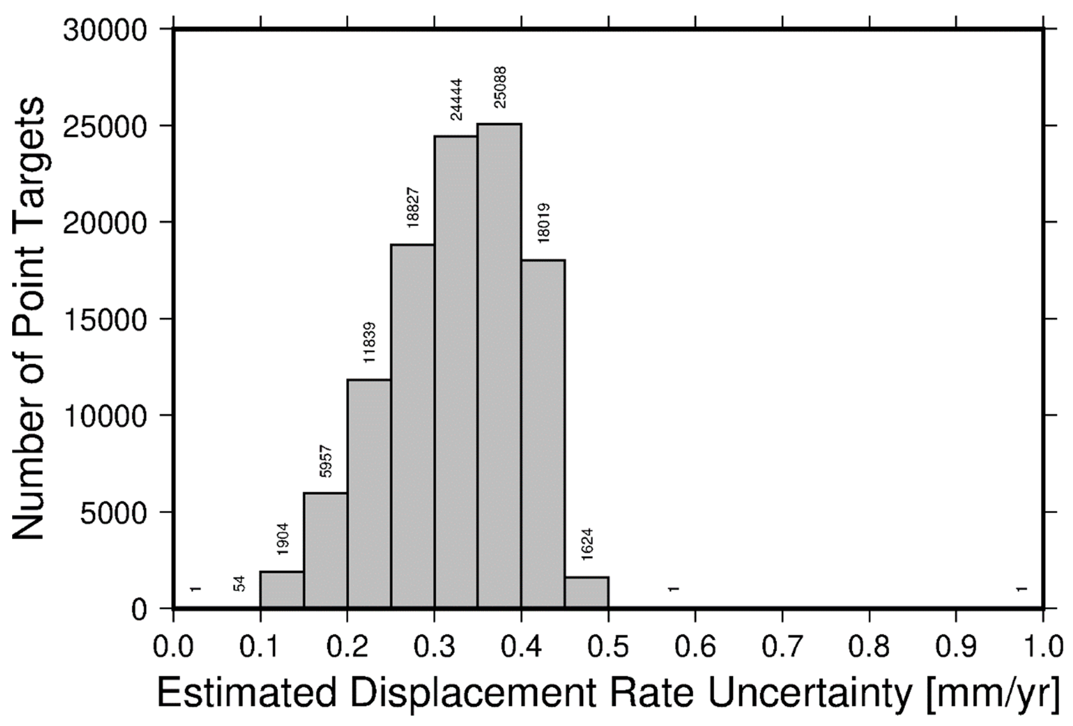
The assessment of the accuracy of the IPTA analysis outcomes can be inferred from the histogram in Figure 8. PT have been grouped in estimated displacement rate uncertainty classes with a bin-width of 0.05 mm/yr. Except very few outliers with values larger than 0.5 mm/yr, most of the targets are grouped in the classes characterized by a displacement rate accuracy ranging from 0.25 to 0.45 mm/yr.
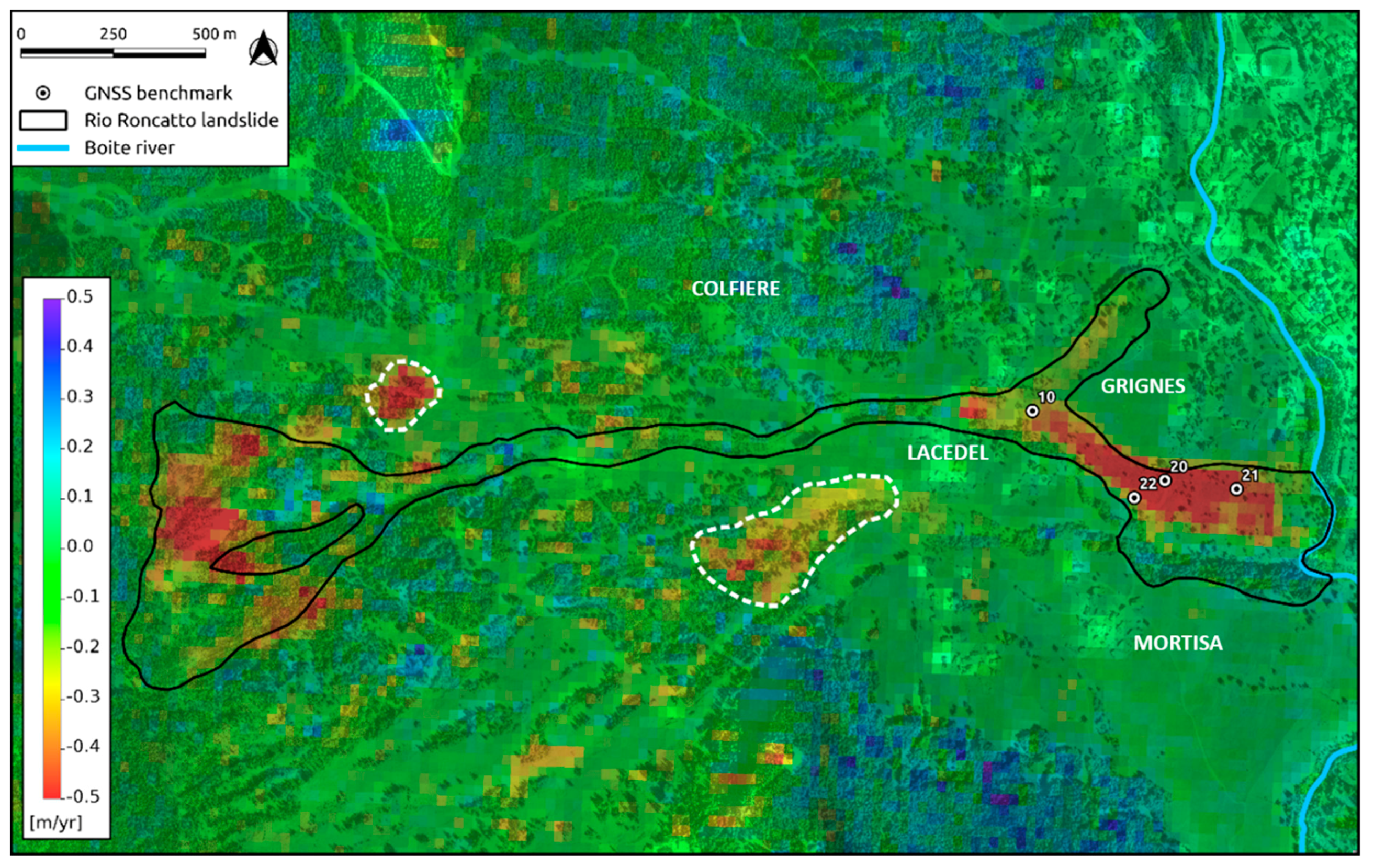
The results of the DInSAR analysis are shown in Figure 9. The pattern of deformation delineates quite well the shape of the Rio Roncatto landslide body mapped from geomorphological evidences. The rate of displacement of the earth flow, assessed along the satellite line of sight (LOS), reaches a peak of 0.5 m/yr, more than an order of magnitude with respect to the values measured with the IPTA technique. The most active sectors of the earth flow are located at the source area of the landslide and to the southern sector of the toe. The sector developing north of Grignes recorded slower rate of displacement rate. Deformation patterns are also clearly evident outside the mapped landslide, specifically north of the source area and uphill with respect to the hamlet of Lacedel (white dotted contours in Figure 9). These findings might suggest an updating of the landslide inventory maps.

5. Discussion

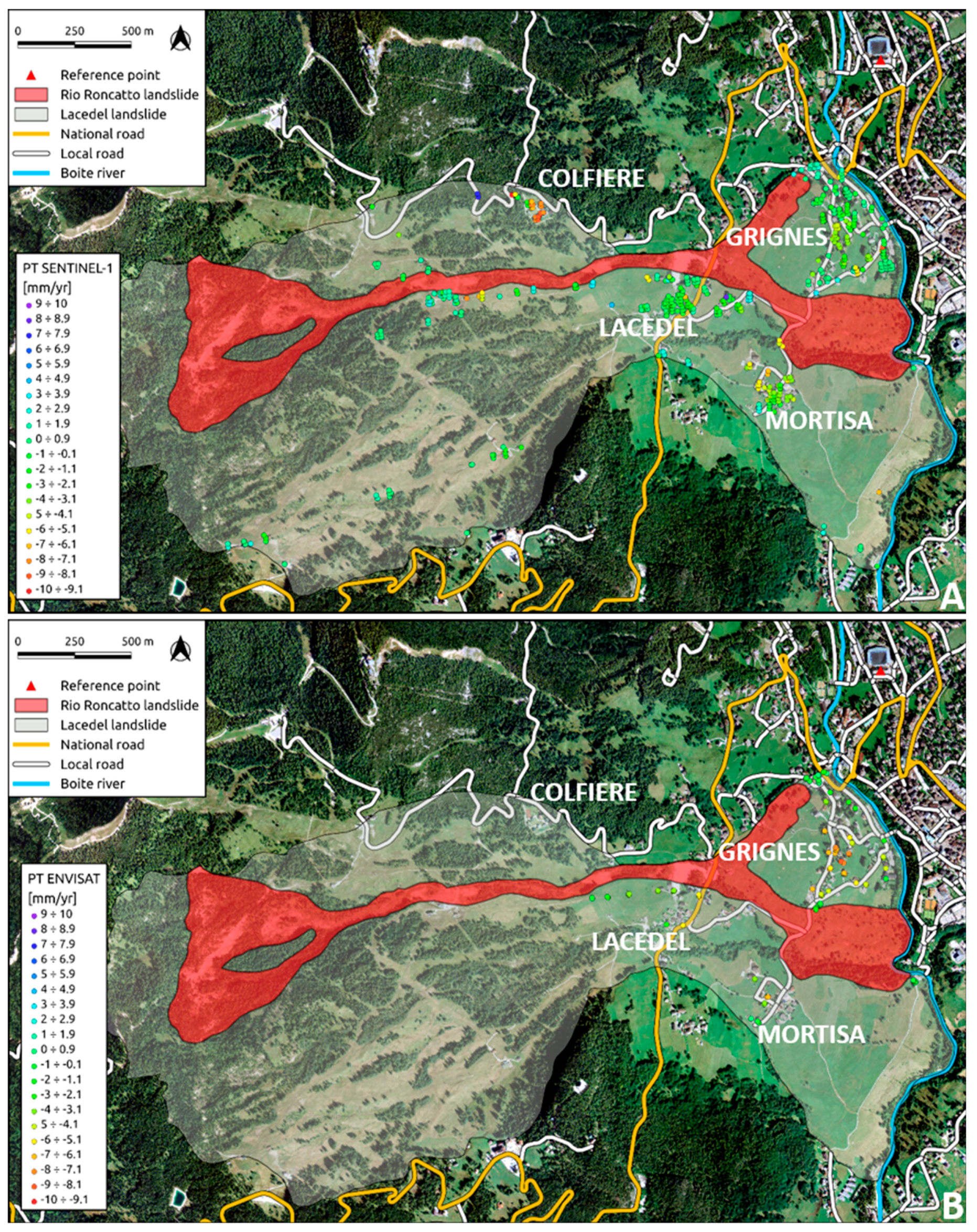
IPTA analysis pointed out patterns of ground displacements attributable to the mass movements affecting the western slope of the Cortina valley and particularly manifest in the built up area of the hamlets Colfiere, Lacedel, Mortisa and Grignes. These results have been matched with the interferometric analysis performed by Bossi et al. (2016) [26] on 34 ENVISAT images acquired from the beginning of April 2004 to the middle of October 2010. Figure 10 sums up the results of IPTA processing performed with S1 and ENVISAT datasets, restricted to the unstable area as mapped by geomorphological evidence.
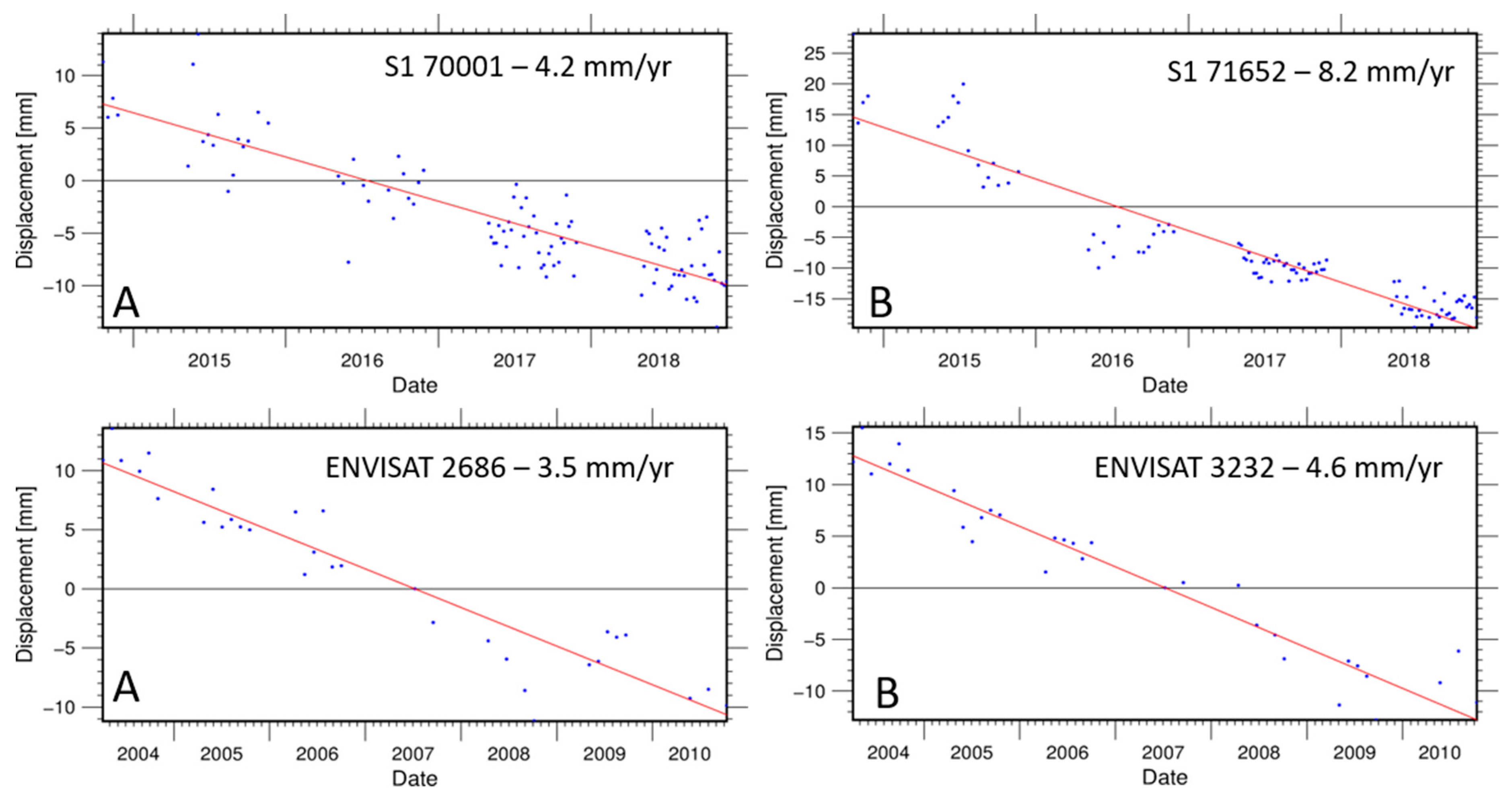
The most obvious remark is that the number of PT in the S1 dataset is much larger than the one in the ENVISAT. The PT located inside the landslide contours are 512 and 101 respectively, meaning that the number of natural reflectors suitable for interferometric analysis are five times larger in the S1 dataset. S1 acquisition mode and the short revisiting time favors the identification of PT leading to an improved spatial sampling and the possibility to infer a greater amount of displacement data in the area of interest. The cluster of PT located over the hamlet of Colfiere in the S1 dataset and absent in the ENVISAT analysis clearly witness the upgrade of the effectiveness of the latest ESA space mission for interferometric purposes. A second consideration can be drawn on the consistency of the S1 dataset. Patterns of deformation are detected in the same sectors of the unstable slope as defined by the ENVISAT data, although with rates slightly different that can be attributable to a change in the style of activity of the landslide and marginally to the different acquisition geometries between S1 and ENVISAT. A comparison between rate of displacement of quasi-homologous PT is shown the graphs reported in Figure 11.
Beside the interesting results of the IPTA processing the outcomes of the DInSAR analysis draw particular attention. If the capability to detect and accurately map the earth flow is clearly highlighted in Figure 8, the reliability of the estimation of the displacement rate needs to be further investigated. In order to achieve this purpose, the cumulated displacement recorded at GNSS benchmarks locations, between the first reading in 2008 and the last one in 2012, has been decomposed and projected along the S1 sensor LOS according to the following formula:
d L O S = ( d E cos θ d N sin θ ) sin φ d H cos φ
Where
  • dLOS: is the cumulated displacement along the LOS,
  • d E = d E 2012 d E 2008 is the cumulated displacement along east coordinate,
  • d N = d N 2012 d N 2008   is the cumulated displacement along north coordinate,
  • d H = d H 2012 d H 2008   is the cumulated displacement along the vertical direction,
  • φ is the sensor look angle,
  • θ is the azimuth direction.
Broadly assuming a linear deformation (Figure 5), the rate of displacement along the LOS can simply be calculated by the following equation:
L O S r a t e =   d L O S t 365
Where
  • LOSrate is the rate of deformation along the LOS,
  • t is the time elapsed between the first and last GNSS measurement expressed in days.
Table 3 summarizes the input data used in the equation and the results calculated for the 4 GNSS benchmarks localized in the lower sector of the Rio Roncatto landslide. Each benchmark location has then been transformed in range-Doppler coordinates (i.e. range and azimuth). The rate of displacement calculated through the interferometric phase of the corresponding image pixel is reported in Table 4.
The results presented in Table 3 are in good agreement with the values inferred by the DInSAR analysis (last column in Table 4), showing that the approach, beside an excellent capability and accuracy of mapping and detection, provides also a reliable estimation of the rate of displacement. By comparing the LOS velocities calculated from the GNSS measurements (GNSS-LOS rate) with the values inferred from the interferometric analysis (LOS rate), a good agreement can be noticed. The maximum difference of 0.155 m/yr is found at ID 20 GNSS benchmark location. It has however to be noticed that, beside the assumption of a constant rate of displacement of the Rio Roncatto earth flow, GNSS-LOS rate were inferred from a 4-year measurement (2008-2012) while LOS rate is calculated on a monthly basis (36 days in 2017), hence discrepancies between the values were expected.

6. Conclusions

The impact of climate change, which results in increasing frequency of extreme meteorological events, makes landslides a worldwide problem of great concern, especially considering the growth of population that leads to the construction of new settlements, the enlargement of cities and the increasing need for infrastructures [32]. Constructions in hazardous areas might lead to unsafe situations and project uncertainties, causing large economic consequences and sometimes casualties. Aiming at an effective risk management and mitigation, the crucial tasks to be achieved are [7]:
  • Detection: where and when deformation occurred (or is occurring);
  • Assessment of the deformation;
  • Evolution (past and future) of the deformation.
Monitoring techniques have always been considered one of the most common tools for risk mitigation and, among these, space-borne interferometry plays a key role. A-DInSAR techniques are currently the only cost-effective approaches for frequent, large-scale monitoring of ground deformation, able to provide the information needed to accomplish the aforementioned objectives. Still these approaches might fail when the inherent characteristics of the mass movements interfere with physical constraints of the technique. Typically, the size, the rate and direction of the mass movements represent the limiting factors to investigate landslides by means of A-DInSAR. Recent space missions, specifically designed for interferometric purposes, such as the ESA S1 satellites, are providing the scientific community with new effective datasets. S1 mission has certainly increased the potential radar interferometry techniques to detect landslides, mainly for the short repeat cycle and the small perpendicular baselines among the acquisitions, besides the timeliness and the reliability of a free of charge service.
Monitoring very slow landslides by means of A-DInSAR analysis is nowadays a well-consolidated practice, but this study has demonstrated how properly designed approaches can extend the field of application of space-borne radar interferometry to the upper class of slow landslides (few metres per year). The landslides affecting the western slope of the Ampezzo valley have been correctly and accurately characterized beside their wide differences and terms of spatial extension and kinematics.
Knowing that the assessment of landslide risk includes both the area affected and the velocity and the product of these two parameters is approximately proportional to the power release of the landslide, the results obtained in the Rio Roncatto earth flow investigations are relevant. The capability to accurately map landslides contours and to carry out reliable displacement measurements allow to produce a data-driven distributed activity map, providing high quality information for geotechnical modelling, which are fundamental to predict risks scenarios and to design mitigation works. It is worth noticing that, prior to the launch of S1, it would have been unfeasible to characterize an earth flow displacing at a velocity in the order of decimetres to metres per year in such a continuous and extensive way. Ultimately, S1 mission has proved to provide a fundamental contribution in the challenging field of landslide risk mitigation and management

Author Contributions

M.M. conceived the paper, performed the interferometric analyses and interpreted the results. G.B., L.S. and G.T. organized and analyzed the data; G.M. and G.Te. supervised the geomorphological field investigations; A.P. led the research. M.M., G.B. and G.Ti. wrote the paper. All the authors contributed to editing and revisions of the paper.

Funding

This research received no external funding.

Acknowledgments

The authors acknowledge the European Space Agency for providing S1 radar images. SAR interferometric analyses were performed using Gamma Software by Gamma Remote Sensing AG. Figures and graphs were produced with QGIS and GMT.

Conflicts of Interest

The authors declare no conflicts of interest.

References

  1. Massonnet, D.; Rossi, M.; Carmona, C.; Adragna, F.; Peltzer, G.; Feigl, K.; Rabaute, T. The displacement field of the Landers earthquake mapped by radar interferometry. Nature 1993, 364, 138–142. [Google Scholar] [CrossRef]
  2. Massonnet, D.; Feigl, K.L. Radar interferometry and its application to changes in the Earth’s surface. Rev. Geophys. 1998, 36, 441–500. [Google Scholar] [CrossRef]
  3. Ouchi, K. Recent Trend and Advance of Synthetic Aperture Radar with Selected Topics. Remote Sens. 2013, 5, 716–807. [Google Scholar] [CrossRef] [Green Version]
  4. Ferretti, A.; Prati, C.; Rocca, F. Permanent scatterers in SAR interferometry. IEEE Trans. Geosci. Remote Sens. 2001, 39, 8–20. [Google Scholar] [CrossRef]
  5. Berardino, P.; Fornaro, G.; Lanari, R.; Sansosti, E. A new algorithm for surface deformation monitoring based on small baseline differential SAR interferograms. IEEE Trans. Geosci. Remote Sens. 2002, 40, 2375–2383. [Google Scholar] [CrossRef] [Green Version]
  6. Colesanti, C.; Ferretti, A.; Prati, C.; Rocca, F. Monitoring landslides and tectonic motions with the Permanent Scatterers Technique. Eng. Geol. 2003, 68, 3–14. [Google Scholar] [CrossRef]
  7. Raucoules, D.; Colesanti, C.; Carnec, C. Use of SAR interferometry for detecting and assessing ground subsidence. C. R. Geosci. 2007, 339, 289–302. [Google Scholar] [CrossRef]
  8. Cigna, F.; Bianchini, S.; Casagli, N. How to assess landslide activity and intensity with Persistent Scatterer Interferometry (PSI): The PSI-based matrix approach. Landslides 2013, 10, 267–283. [Google Scholar] [CrossRef]
  9. Colesanti, C.; Wasowski, J. Investigating landslides with space-borne Synthetic Aperture Radar (SAR) interferometry. Eng. Geol. 2006, 88, 173–199. [Google Scholar] [CrossRef]
  10. Cruden, D.M.; Varnes, D.J. Landslide Types and Processes. Spec. Rep. Natl. Acad. Sci. Transp. Res. Board 1996, 247, 36–75. [Google Scholar]
  11. Bovenga, F.; Wasowski, J.; Nitti, D.O.; Nutricato, R.; Chiaradia, M.T. Using COSMO/SkyMed X-band and ENVISAT C-band SAR interferometry for landslide analysis. Remote Sens. Environ. 2012, 119, 272–285. [Google Scholar] [CrossRef]
  12. Herrera, G.; Gutiérrez, F.; García-Davalillo, J.C.; Guerrero, J.; Notti, D.; Galve, J.P.; Fernández-Merodo, J.A.; Cooksley, G. Multi-sensor advanced DInSAR monitoring of very slow landslides: The Tena Valley case study (Central Spanish Pyrenees). Remote Sens. Environ. 2013, 128, 31–43. [Google Scholar] [CrossRef]
  13. Tofani, V.; Raspini, F.; Catani, F.; Casagli, N. Persistent Scatterer Interferometry (PSI) Technique for Landslide Characterization and Monitoring. Remote Sens. 2013, 5, 1045–1065. [Google Scholar] [CrossRef] [Green Version]
  14. Mantovani, M.; Devoto, S.; Piacentini, D.; Prampolini, M.; Soldati, S.; Pasuto, A. Advanced SAR Interferometric Analysis to Support Geomorphological Interpretation of Slow-Moving Coastal Landslides (Malta, Mediterranean Sea). Remote Sens. 2016, 8, 443. [Google Scholar] [CrossRef]
  15. Necula, N.; Niculițua, M.; Tessari, G.; Floris, M. InSAR analysis of Sentinel-1 data for monitoring landslide displacement of the north-eastern Copou hillslope, Iași city, Romania. In Proceedings of the Romanian Geomorphology Symposium, Iasi, Romania, 11 May 2017; Volume 1, pp. 85–88. [Google Scholar]
  16. Barra, A.; Monserrat, O.; Crosetto, M.; Cuevas-Gonzalez, M.; Devanthéry, N.; Luzi, G.; Crippa, B. Sentinel-1 Data Analysis for Landslide Detection and Mapping: First Experiences in Italy and Spain. In Proceedings of the Workshop on World Landslide Forum, Ljubljana, Slovenia, 29 May–2 June 2017. [Google Scholar]
  17. Panizza, M.; Pasuto, A.; Silvano, S.; Soldati, M. Temporal occurrence and activity of landslides in the area of Cortina d’Ampezzo (Dolomites, Italy). Geomorphology 1996, 15, 311–326. [Google Scholar] [CrossRef]
  18. Pasuto, A.; Soldati, M. Some cases of deep-seated gravitational deformations in the area of Cortina d’Ampezzo (Dolomites). Implications in environmental assessment. In Implications in Environmental Risk Assessment European Experimental Course on Applied Geomorphology; Panizza, M., Soldati, M., Coltellacci, M., Eds.; Istituto di Geologia—Università degli Studi: Modena, Italy, 1991; pp. 91–104. [Google Scholar]
  19. Pasuto, A.; Soldati, M. The use of landslide units in geomorphological mapping: An example in the Italian Dolomites. Geomorphology 1999, 30, 53–64. [Google Scholar] [CrossRef]
  20. Soldati, M.; Corsini, A.; Pasuto, A. Landslides and climate change in the Italian Dolomites since the Late glacial. Catena 2004, 55, 141–161. [Google Scholar] [CrossRef]
  21. Panizza, M. Glacio pressure implications in the production of landslides in the Dolomitic area. Geol. Appl. Idrogeol. 1973, 8, 289–297. [Google Scholar]
  22. Vandelli, V.; Ghinoi, A.; Marchetti, M.; Soldati, M. Discovery and dating of Pre-LGM deposits in a high catchment of the Dolomites (Italy): New insights on climate-related geomorphological processes during the Late Pleistocene. Geomorphology 2019, 332, 22–32. [Google Scholar] [CrossRef]
  23. Borgatti, L.; Soldati, M. Landslides as a geomorphological proxy for climate change: A record from the Dolomites (northern Italy). Geomorphology 2010, 120, 56–64. [Google Scholar] [CrossRef]
  24. Angeli, M.-G.; Pasuto, A.; Silvano, S. Towards the definition of slope instability behaviour in the Alverà mudslide (Cortina d’Ampezzo, Italy). Geomorphology 1999, 30, 201–211. [Google Scholar] [CrossRef]
  25. Bossi, G.; Borgatti, L.; Gottardi, G.; Marcato, G. Quantification of the uncertainty in the modelling of unstable slopes displaying marked soil heterogeneity. Landslides 2019, 1–12. [Google Scholar] [CrossRef]
  26. Bossi, G.; Mantovani, M.; Frigerio, S.; Schenato, L.; Marcato, G.; Pasuto, A. A monitoring network to map and assess landslide activity in a highly anthropized area. Geosciences 2016, 6, 40. [Google Scholar] [CrossRef]
  27. Geudtner, D.; Torres, R.; Snoeij, P.; Davidson, M.; Rommen, B. Sentinel-1 System capabilities and applications. In Proceedings of the 2014 IEEE Geoscience and Remote Sensing Symposium, Quebec City, QC, Canada, 13–18 July 2014; pp. 1457–1460. [Google Scholar]
  28. Lanari, R.; Berardino, P.; Bonano, M.; Casu, F.; De Luca, C.; Elefante, S.; Fusco, A.; Manunta, M.; Manzo, M.; Ojha, C.; et al. Sentinel-1 results: SBAS-DInSAR processing chain developments and land subsidence analysis. In Proceedings of the 2015 IEEE International Geoscience and Remote Sensing Symposium (IGARSS), Milan, Italy, 26–31 July 2015; pp. 2836–2839. [Google Scholar]
  29. Rabus, B.; Eineder, M.; Roth, A.; Bamler, R. The shuttle radar topography mission—A new class of digital elevation models acquired by spaceborne radar. ISPRS J. Photogramm. Remote Sens. 2003, 57, 241–262. [Google Scholar] [CrossRef]
  30. Werner, C.; Wegmuller, U.; Strozzi, T.; Wiesmann, A. Interferometric point target analysis for deformation mapping. In Proceedings of the 2003 IEEE International Geoscience and Remote Sensing Symposium, Toulouse, France, 21–25 July 2003; Volume 7, pp. 4362–4364. [Google Scholar]
  31. Costantini, M. A novel phase unwrapping method based on network programming. IEEE Trans. Geosci. Remote Sens. 1998, 36, 813–821. [Google Scholar] [CrossRef]
  32. Borgatti, L.; Soldati, M. Landslides and climatic change. In Geomorphological Hazards and Disaster Prevention; Alcantara-Ayala, I., Goudie, A.S., Eds.; Cambridge University Press: Cambridge, UK, 2010; pp. 87–96. [Google Scholar]
Figure 1. Three-dimensional perspective of the western slope of the Cortina d’Ampezzo valley. The Lacedel and the Rio Roncatto landslides are highlighted in white and in red respectively. The red square over the map in the inset denotes the location of Cortina d’Ampezzo, while the dashed blue area represents the swath of the S1 acquisitions (background image Microsoft® Bing™ Maps, roads layer © OpenStreetMap contributors).
Remotesensing 11 02135 g001
Figure 2. Buildings damaged and roads disrupted by the movement of the Rio Roncatto landslide.
Remotesensing 11 02135 g002
Figure 3. Interferometric baselines graph. The numbers identify the images plotted in order of date of acquisition (x-axis) and in function of the perpendicular baseline (y-axis) with respect to the master image. Red lines represent the interferograms.
Remotesensing 11 02135 g003
Figure 4. Wrapped differential interferograms with a temporal baseline of 6 days in range-Doppler coordinates. Inside the white dotted rectangular the Rio Roncatto landslide shape is clearly visible.
Remotesensing 11 02135 g004
Figure 5. GNSS benchmarks location associated with the displacement time series graphs from year 2008 to 2012 (roads layer © OpenStreetMap contributors).
Remotesensing 11 02135 g005
Figure 6. S1 dataset IPTA analysis over the western slope of Cortina d’Ampezzo valley (background image Microsoft® Bing™ Maps).
Remotesensing 11 02135 g006
Figure 7. Histogram representing the number of PT within displacement rate classes.
Remotesensing 11 02135 g007
Figure 8. Histogram representing the number of PT within estimated displacement rate uncertainty classes.
Remotesensing 11 02135 g008
Figure 9. Deformation rate of the Rio Roncatto landslide assessed by six interferograms generated from images acquired in the Autumn of 2017. The white lines contour unstable areas outside the mapped landslide body.
Remotesensing 11 02135 g009
Figure 10. Results of IPTA processing performed with S1 (A) and ENVISAT (B) datasets, restricted to the unstable area as mapped by geomorphological evidences (roads layer © OpenStreetMap contributors).
Remotesensing 11 02135 g010
Figure 11. Time series displacements of quasi-homologous PT located in the hamlet of Mortisa (A) and Grignes (B).
Remotesensing 11 02135 g011
Table 1. Landslide movement scale as proposed by Cruden and Varnes [10].
Velocity classDescriptionTypical velocity
7Extremely rapid5 m/s
6Very rapid3 m/min
5Rapid1.8 m/h
4Moderate13 m/month
3Slow1.6 m/year
2Very slow16 mm/year
1Extremely slow
Table 2. Features and technical parameters of the S1 mission.
Launch date3 April 2014 (A), 25 April 2016 (B)
Lifetime7 years with consumable for 12 years
Orbit typenear polar, sun-synchronized
Orbit altitude697 km
Orbit repeat cycle12 days, 6 days (A+B)
Orbit deviation tube (RMS)+/- 50 m
SAR frequency5.4 GHz
Incidence angle range20°–45°
Acquisition modeSMIWEWWV
Swath width80 km250 km400 km20 km
Geometric resolution [rg x az]1.7x4.3 to 3.6x4.9 m2.7x22 to 3.5x22 m7.9x43 to 15x43 m2.0x4.8 to 3.1x4.8 m
Pixel spacing [rg x az]1.5x3.6 to 3.1x4.1 m2.3x14.1 m5.9x19.9 m1.7x4.1 to 2.7x4.1 m
Table 3. GNSS benchmarks measurements and acquisition parameters used for the LOS displacement rate conversion.
TRACKORBITθ [deg]φ [deg]t [days]
44A-10.901433.73181368
GNSS ID.dE [m]dN [m]dH [m]dLOS [m]GNSS-LOS rate [m/yr]
101.667-0.183-0.1120.9910.264
203.811-0.783-0.7602.6280.701
212.936-0.345-0.5372.0110.537
222.670-2.871-0.8531.8640.497
Table 4. LOS displacement calculated by the interferometric analysis at each benchmark location.
Geographic CoordinatesRange-Doppler Coordinates
GNSS ID.Lon. [deg.]Lat. [deg.]H. [m]Ra [pix]Az [pix]LOS rate [m/yr]
1012.12482446.535908135528926950.197
2012.12958946.534332128629936780.546
2112.13213646.534185125930476740.520
2212.12853146.533881129729696760.439