Article

The ASI Integrated Sounder-SAR System Operating in the UHF-VHF Bands: First Results of the 2018 Helicopter-Borne Morocco Desert Campaign

by
Stefano Perna
1,2,*,
Giovanni Alberti
3,
Paolo Berardino
1,
Lorenzo Bruzzone
4,
Dario Califano
3,
Ilaria Catapano
1,
Luca Ciofaniello
3,
Elena Donini
4,
Carmen Esposito
1,
Claudia Facchinetti
5,
Roberto Formaro
5,
Gianluca Gennarelli
1,
Christopher Gerekos
4,
Riccardo Lanari
1,
Francesco Longo
5,
Giovanni Ludeno
1,
Mauro Mariotti d’Alessandro
6,
Antonio Natale
1,
Carlo Noviello
1,
Gianfranco Palmese
3,
Claudio Papa
3,
Giulia Pica
3,
Fabio Rocca
6,
Giuseppe Salzillo
3,
Francesco Soldovieri
1,
Stefano Tebaldini
6 and
Sanchari Thakur
4
add Show full author list remove Hide full author list
1
Institute for Remote Sensing of Environment (IREA), National Research Council (CNR), 80124 Napoli, Italy
2
Department of Engineering (DI), Università degli Studi di Napoli “Parthenope”, 80143 Napoli, Italy
3
CO.RI.S.T.A., COnsorzio di RIcerca su Sistemi di Telesensori Avanzati, 80143 Napoli, Italy
4
Department of Information Engineering and Computer Science, University of Trento, 38123 Trento, Italy
5
Agenzia Spaziale Italiana, Via del Politecnico, 00133 Roma, Italy
6
Department of Electronics, Information, and Bioengineering (DEIB), Politecnico di Milano, 20133 Milano, Italy
*
Author to whom correspondence should be addressed.
Remote Sens. 2019, 11(16), 1845; https://doi.org/10.3390/rs11161845
Submission received: 21 June 2019 / Revised: 3 August 2019 / Accepted: 5 August 2019 / Published: 8 August 2019

Abstract

:
This work is aimed at showing the present capabilities and future potentialities of an imaging radar system that can be mounted onboard flexible aerial platforms, such as helicopters or small airplanes, and may operate in the UHF and VHF frequency bands as Sounder and as Synthetic Aperture Radar (SAR). More specifically, the Sounder operates at 165 MHz, whereas the SAR may operate either at 450 MHz or at 860 MHz. In the work, we present the first results relevant to a set of Sounder and SAR data collected by the radar during a helicopter-borne campaign conducted in 2018 over a desert area in Erfoud, Morocco, just after the conclusion of a system upgrading procedure. In particular, a first analysis of the focusing capabilities of the Sounder mode and of the polarimetric and interferometric capabilities of the SAR mode is conducted. The overall system, originally developed by CO.RI.S.T.A. according to a ASI funding set up in 2010, has been upgraded in the frame of a contract signed in 2015 between ASI and different private and public Italian Research Institutes and Universities, namely CO.RI.S.T.A., IREA-CNR, Politecnico di Milano and University of Trento.

Graphical Abstract

1. Introduction

Radar imaging [1] represents a powerful tool in several applications, such as security, surveillance, and environmental monitoring, with particular emphasis on disasters and crisis management [2,3,4]. In this frame, radar systems mounted onboard aerial platforms, such as airplanes [5,6,7,8], helicopters and drones [9], are gaining increasing interest due to their features allowing to overcome several limitations of radar systems mounted onboard terrestrial vehicles (carts, cars, ground track rails) [10,11] or spaceborne platforms [12,13,14].
More specifically, if compared to the terrestrial imaging radar systems, such as the conventional Ground Penetrating Radar (GPR) [10] or the Ground Based (GB) Synthetic Aperture Radar (SAR) [11], the aerial imaging radar systems are flexible and able to ensure a wider spatial coverage. Furthermore, in critical scenarios, as the ones induced for instance by natural disasters (Earthquakes, volcanoes’ eruptions, flooding, rapid landslides), ungentle climatic conditions (cryosphere monitoring) or anthropic actions (ordnance deployment), they allow safe monitoring of areas that would be difficult to reach (if not unreachable) through terrestrial systems.
On the other side, in contrast to the satellite platforms [12,13,14], the aerial ones allow to timely reach the area of interest, to fly practically along any direction, and to keep very short the so called revisiting time, that is, the time interval elapsing between subsequent observations of the same area.
In addition, the aerial radar systems are relatively cheap, thus offering the appealing opportunity of assessing the potentialities of novel technologies and/or measurement modalities, before these are made operative on expensive spaceborne missions.
In this regard, the increasing interest registered in the last years toward aerial radar systems operating at low frequencies has been in some extent driven by the ongoing or future spaceborne missions. Indeed, the exploitation of GPR systems for the ongoing planetary exploration missions [15,16,17,18,19] has certainly taken benefit from the results obtained through the several experimental campaigns carried out in the last years with aerial penetrating radar (usually named Sounder) systems operating in the HF, UHF and VHF bands [20,21,22,23,24,25,26,27,28,29,30,31,32,33]. For the same reason, in anticipation of the forthcoming spaceborne ESA-Biomass mission [34], increasing of the number of aerial P-Band SAR missions is registered in the last years [35,36,37,38,39,40,41,42,43,44,45,46].
In this context, the Italian Space Agency (ASI) has recently funded the development of an aerial multi-mode pulsed imaging radar system operating in a multi-frequency modality in the UHF and VHF bands. In particular, the system is able to work either as Sounder or as full polarimetric SAR. The development of this system is aimed at making available to the Italian community of researchers and end-users an aerial imaging radar system with several attractive features. First, it grows the relatively small family of available aerial SAR [35,36,37,38,39,40,41,42,43,44,45,46,47,48,49,50,51,52,53,54,55,56,57,58] and Sounder [23,24,26,59] systems operating in the UHF and VHF bands. Secondly, the system allows to easily collect over the same area radar data characterized by different scattering mechanisms (since it may work either as SAR or as Sounder), at different carrier frequencies and (for the SAR modes) with a diversity in the polarization.
The overall system has been originally developed by CO.RI.S.T.A. [47] according to an ASI funding set up in 2010. After, the first version of the system has been upgraded, again by CO.RI.S.T.A., in the frame of a contract signed in 2015 between ASI, CO.RI.S.T.A. and different public Italian Research Institutes and Universities, namely IREA-CNR, Politecnico di Milano and University of Trento, which have been entrusted with the processing of the data acquired by the radar. In particular, they have designed ad-hoc strategies to process the both Sounder and SAR data. These strategies exploit the navigation information acquired during the flight and adopt model-based procedures, which are the microwave tomographic imaging for the Sounder and the back-projection procedure for the SAR.
With the aim of obtaining a first assessment of the performances of this radar system, a helicopter-borne campaign has been conducted in 2018 over a desert area in Erfoud, Morocco. During the campaign, several tracks have been flown exploiting all the three different operational modes of the system. In this work, we present first results relevant to a small subset picked up from the huge dataset collected by the system during this campaign.
The work is organized as follows. In Section 2 we provide a brief description of the system. The acquisition campaign is described in Section 3. The processing chain applied to the Sounder data is illustrated in Section 4 along with some first results. Similarly, the SAR data processing chain is described in Section 5 along with the corresponding first results. Section 6 is devoted to the concluding remarks.

2. System Description

The radar system exploits the pulsed radar technology and can operate at different carrier frequencies as Sounder and Synthetic Aperture Radar (SAR). More specifically, the Sounder operates at 165 MHz, whereas the SAR may operate either at 450 MHz (SAR-Low mode) or at 860 MHz (SAR-High mode). Summing up, three operational modes are enabled, namely, Sounder, SAR-Low and SAR-High, each working at a different frequency.
The bandwidth of the transmitted (chirp) pulses is 40 MHz, leading to a (slant) range resolution of 3.75 m (in air). Moreover, in the SAR-High mode, through the stepped chirp technology [60], an overall bandwidth of 80 MHz can be reached, that is, a (slant) range resolution of 1.87 m. The SAR system is full polarimetric thanks to two separate receiving channels.
The overall system basically consists of a radar module along with three different antennas, one for each operational mode.
The radar module consists of three main blocks, namely, the Radar Digital Unit (RDU), the Radio Frequency Unit (RFU) and the Power Supply Unit (PSU). In particular, the RDU is fully programmable and allows the parameters setting, the timing generation and the data handling. It also includes the Analog to Digital Converter (ADC) and the data storage unit. The RFU embeds the frequency generation unit (which generates all the synchronization and radio frequency signals) and the chirp generator unit (which generates the low frequency modulated chirp signal by means of the digital direct synthesis technology). RFU also includes the high power amplification unit, which is based on the solid state technology, and an antenna front-end that allows the correct switching among the transmitted and received signals and among the different polarizations of the SAR mode. The PSU provides the power supply to whole system by an external 28 V DC voltage.
The system is completely stand-alone: the power supply connector is the only electrical interface. Most radar modules are shared by the three different operational modes of the system. In particular, base band signal generation, base band data sampling and data handling are common to the Sounder and the SAR modes.
As noted above, different antennas are used for the three different operational modes of the system. In particular, for the Sounder mode, a low-gain log-periodic antenna is deployed; the antenna points to the nadir and radiates the main beam with Half Power Beam Width (HPBW) [61] of 68° and 50° in the range and azimuth directions, respectively, and with a (maximum) gain [61] of 7dBi[1]. Exploitation of the overall azimuth aperture thus can lead to an azimuth resolution of about 1m [62,63]. Two different side-looking arrays of micro-strip antennas are instead employed for the two different SAR modes [64]. In particular, these two SAR antennas have the same shape and size, to allow an easier swap when they cannot be installed simultaneously on the airplane/helicopter. More specifically, the array used for the SAR-Low mode consists of 4 patches deployed along the azimuth direction: its (maximum) gain is 11 dBi and its HPBWs are 75° and 20° in the range and azimuth directions, respectively. Exploitation of the overall azimuth aperture thus leads to an azimuth resolution of about 1m [62,63]. For the SAR-High mode (which operates at a carrier wavelength scaled about of a factor two respect to the SAR-Low mode), a planar array antenna of 8 × 2 patches is deployed, with the same overall dimensions of the array used for the SAR-Low mode. The corresponding HPBWs are thus reduced of a factor two (in both directions) with respect to the SAR-Low mode. This allows increasing the (maximum) antenna gain of 6 dBi, retaining practically the same achievable azimuth resolution obtainable with the SAR-Low mode. Both SAR antennas are dual-polarized, to enable the full polarimetric capability of the SAR modes.
Currently, during the flight the user can select manually one of the three operational modes of the system. At present, the different operational modes cannot be used simultaneously; development of a synchronization solution aimed at circumventing this limitation is however straightforward and is matter of current activities.
In order to achieve accurate flight information, necessary for the reliable processing of both Sounder and SAR data, the radar encompasses a navigation unit consisting of an Inertial Navigation System (INS) that embeds a Global Positioning System (GPS). In particular, the INS is a MTi model of Xsense Technologies B.V., which is an inertial measurement unit with integrated 3D magnetometers (3D compass), with an embedded processor capable of calculating roll, pitch and yaw in real time, as well as outputting calibrated 3D linear acceleration, rate of turn (gyro) and (Earth) magnetic field data. The INS device integrates a GPS receiver and the related information, position, velocity and time (PVT). The navigation unit is directly connected to the radar central unit by means of an USB interface; all the navigation data are synchronized with the radar pulses and embedded in its output data. Furthermore, two additional GPS devices have been added to allow differential processing of the positioning data. The two GPS receivers are based on M8T chip series of U-blox, one installed onboard, close to the SAR antenna, and the other on the ground in the range of some kilometers from the flying radar. During the calibration campaigns of the radar, differential processing of the positioning data, carried out with the RTKLIB library, allowed a centimetric positioning accuracy.
The overall system is easy to be transported and installed onboard relatively small airplanes or helicopters. Indeed, the radar module is stowed in a rack, which is quite compact and with dimensions of 50 cm × 50 cm × 65 cm, for a weight of about 30 kg.
During the campaign, the radar system was installed on an Eurocopter AS-350 series helicopter (see Figure 1a). In particular, the radar electronics rack was accommodated in the helicopter cabin, in place of the two rear passenger seats (see Figure 1b). The sounder antenna is installed on the helicopter nose (see Figure 1c) through the mechanical framework normally used for handling the rear-view mirror; moreover, it is fixed to the front glass and to the fuselage by means of a standard adapter. The SAR antennas are installed through a certified framework normally used for side-looking cameras and by using a honeycomb panel and some brackets (see Figure 1d, where just one SAR antenna is shown).
Table 1 reports the main electrical, mechanical and geometrical parameters of the system.

3. Campaign Description

The flight campaign was carried out in May 2018 over an arid region located in southeastern Morocco, around the city of Erfoud at the northern edge of the Sahara Desert. Several tracks, covering different test sites, have been flown by exploiting all the three available radar acquisition modes. As observed above (see again Figure 1), the radar system was installed onboard an Eurocopter AS-350 series helicopter, and it was possible to embark onboard simultaneously the Sounder antenna and only one SAR antenna. Exploitation of the two different SAR modes has thus required during the mission the swap of the two different SAR antennas.
In order to minimize the effects of structural vibration noise, during the campaign the INS has been placed inside the helicopter cabin (as close as possible to the SAR antenna) on the floor, by using vibration absorbers.
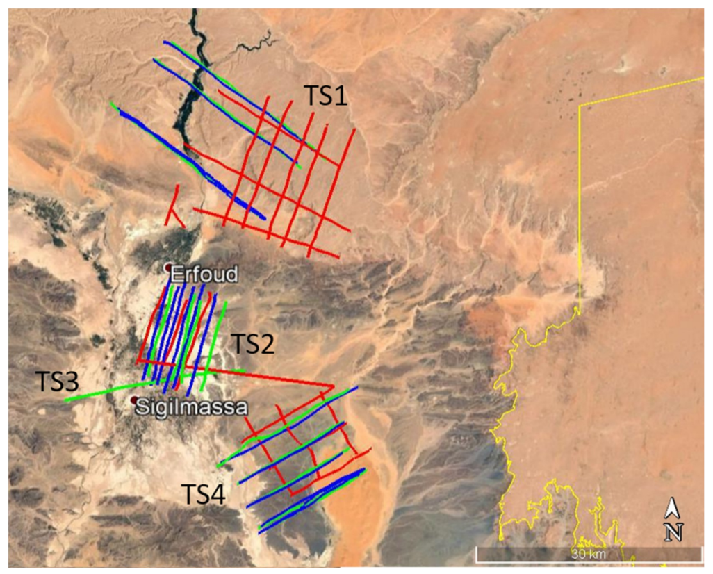
Figure 2 shows all the tracks flown during the campaign, superimposed to an optical image of the overall test area. In particular, the red, green and blue tracks are relevant to the acquisitions carried out with the Sounder, SAR-Low and SAR-High modes, respectively. As can be seen, the flight tracks were flown basically over four different test sites that in the following are named TS1, TS2, TS3 and TS4, respectively. More specifically, the test site TS1, which is located in proximity of the cities of Errachidia and Erfoud, covers an aquifer located in cretaceous rocks at a depth ranging approximatively between 100 m and 200 m. The test sites TS2 and TS3 are both located in proximity of the city of Rissani. In particular, TS2, which belongs to the great Basin Ziz-Rheris, is an almost flat region characterized by alluvial sediments with the presence of aquifers at depth varying approximatively between 20 m and 40 m, whereas TS3 includes the archeological area of Sijilmasa. The test site TS4 is located in proximity of the Erg Chebbi and is characterized by the presence of several dunes and covers an aquifer located at a depth ranging approximatively between 150 m and 200 m.

4. Data Processing and Experimental Results: Sounder Mode

Sounder raw data acquired during the campaign have been delivered by CO.RI.S.T.A. and processed by IREA-CNR and University of Trento.

4.1. Data Processing

Like any penetrating radar, the Sounder data collected onboard, usually named raw-data, are arranged in a two-dimensional matrix representing the radar echoes as a function of the fast time and the slow time, which are related to the two-way sensor-to-target distance (range) and the position of the sensor along the flight trajectory (azimuth), respectively. The main rationale of the processing chain applied to focus these raw data is shown in Figure 3 and consists of the cascade of four steps.
The first step is an azimuth pre-summing aimed at improving the signal-to-noise ratio. In this regard, it is noted that the Sounder PRF (500 Hz, see Table 1) leads to a spectral window significantly larger than the Doppler bandwidth (about 40 Hz) achievable with the available azimuth beam (50°, see again Table 1) and the platform velocity (on the order of 40 m/s). Accordingly, the pre-summing factor can be safely set on the order of 10 or even more. In the cases at hand, a factor of 20 has been applied along with a proper anti-aliasing filtering procedure.
The second processing step (see again Figure 3) is the chirp pulse compression [65], which includes also the application of a spectral windowing procedure (in the case at hand, we use Hamming window) aimed at reducing the level of the secondary lobes of the impulse response relevant to the range-focused image.
Following this step, the data are still not focused along the azimuth direction: they are thus generally characterized by the presence of diffraction hyperbolas that can make very difficult the interpretation of the radar image. The data interpretation is further complicated by the fact that the Sounder acquisition is typically corrupted by the so called motion errors, that is, the deviations of the flown flight track with respect to an ideal rectilinear path. Indeed, the motion errors, if not properly accounted for, produce distortion effects on the final radar image. For instance, in the presence of altitude variations, a flat surface (for instance a lake) is imaged in the Sounder data as a curve specular to the flight path instead of being seen as flat [66]. Application of a proper data processing step aimed at reducing all these effects is thus needed at this stage. In our case, the azimuth focusing procedure, including the compensation of the motion errors, is carried out in the frequency domain. In particular, following the application of a Fast Fourier Transform (FFT) algorithm along the range direction (see again the processing chain of Figure 3), the microwave tomography algorithm described below is applied.
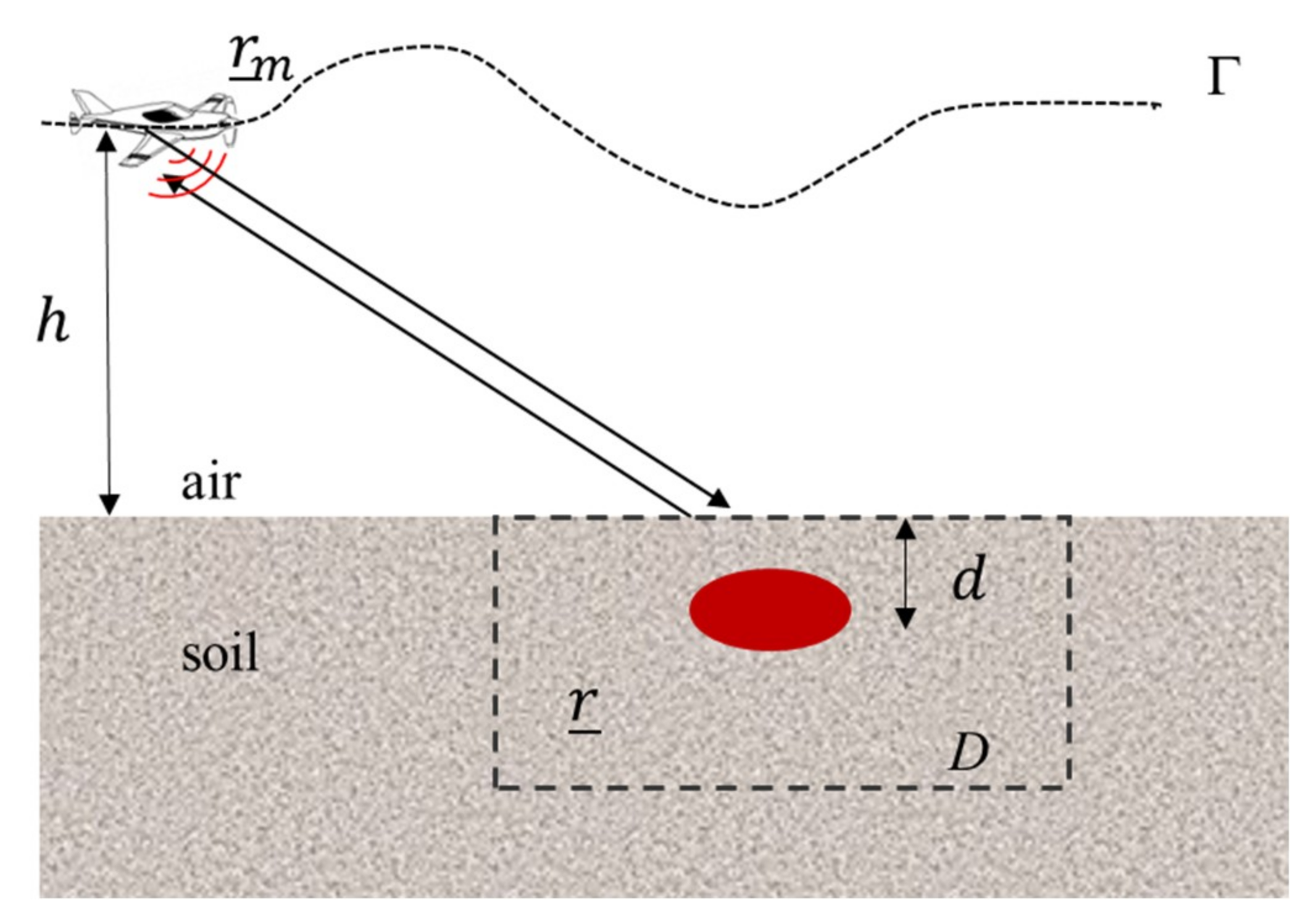
To this aim, let us consider the two-dimensional Sounder acquisition geometry shown in Figure 4. Γ is the flight path that, as observed above, is typically not a straight line, that is, the flight altitude with respect to the ground is variable. rm represents the generic measurement position, that is, the antenna phase center position at a generic azimuth time, say tm. Let D be the 2D domain of investigation within which we assume the targets of interest are present and let r be the position of a generic point in D. The applied tomographic reconstruction approach is based on the following assumptions:
  • the scene under investigation is invariant along the direction perpendicular to the plane defined by the normal to the ground and the (nominal) flight direction (2D geometry);
  • the radar antenna is located in the far zone with respect to the investigated area. Moreover, the transmitting antenna is modeled as an electrical line source perpendicular to the survey plane;
  • the propagation in the soil is negligible because the flight altitude is much greater than the depth of the target of interest. This approximation is acceptable when the goal is to locate shallow targets;
  • the measurement configuration is multimonostatic/multifrequency so that, at each measurement point rm, the radar illuminates the scene at nadir and collects the field scattered by the targets at the same measurement point rm, within the frequency band of the transmitted signal;
  • a linearized model of the electromagnetic scattering equations is exploited [67].
According to the above assumptions, the electromagnetic scattering phenomenon is governed by the integral equation [67]:
E s ( r _ m , ω ) = k 0 2 D g ( r _ m , r _ ) E i n c ( r _ ) χ ( r _ ) d r _ = A χ
where E s is the co-polar component of the field scattered by the target (data) and received by the antenna in rm at the frequency ω, k0 is the propagation constant in free-space, Einc is the incident electric field in D, χ is the so called contrast function, which is different from zero in the target regions and zero elsewhere. Moreover, A is a linear operator that maps the space of the unknowns in the data space and
g ( r _ m , r _ ) e j k | r _ r _ m | | r _ r _ m |
accounts for the scalar Green’s function in free-space [67]. The inverse problem defined by the Equation (1) is ill posed; adoption of a regularization scheme is thus necessary to obtain a stable and robust solution with respect to the data noise [68]. A simple inversion scheme that provides a regularized solution to the inverse problem is that based on the adjoint operator A + [68]:
χ ( r _ ) = A + E s = ( g ( r _ m , r _ ) E i n c ( r _ ) ) * E s ( r _ m , ω ) d r _ m d ω
where the symbol ‘*’ denotes the conjugation operator. The module of the contrast function | χ ( r _ ) | , obtained through the Equation (3), represents the focused tomographic image I to be used for the subsequent analysis and interpretation. It is worth stressing that, despite the adjoint inversion scheme defined by Equation (3) is computationally efficient, the computational resources required are in any case high for the imaging problem at hand since large-scale (in terms of probing wavelength) data have to be processed. For this reason, we decided to adopt a shifting zoom approach [69], whose main steps are shown in Figure 5. More specifically, the measurement domain Γ and the survey area D are first partitioned into N partially overlapping subdomains, say Γi and Di, i = 1,…,N. Then, for each subdomain Di the reconstruction Ii is obtained by the adjoint inversion. The tomographic image relevant to the whole survey area D is finally obtained by combining the reconstructions Ii relating to the subdomains Di. Note that splitting the data processing domain in partially overlapping subintervals reduces the computational burden and in particular the memory occupation. In our case, the dimension of the azimuth partitioning has been chosen in the interval [150, 200] m.
Note also that the inversion procedure described above makes it possible to process the data acquired in the presence of arbitrary flight paths, provided that the measurement positions rm are known. In this regard, it is remarked that the accurate position of the measurement points is provided by the embedded INS-GPS device mounted onboard the platform. It is also stressed that, similarly to the SAR case, accounting for the actual flight track leads to an increase in the computational complexity with respect to the focusing procedures that are based upon the assumption of straight-line flight trajectories [70,71].

4.2. First Results

As shown in Figure 2 (red tracks), the sites TS1, TS2 and TS4 were inspected with the Sounder mode. In particular, for each test site, repeated passages of the helicopter have been flown and among the overall acquired dataset, we report in the following some representative reconstruction results.
Figure 6 reports (right panel) the amplitude of the focused Sounder image relevant to a track flown over the site TS1. The left panel reports the Google Earth ortophoto including the observed area. The red line represents the flight track projected on the ground. The focused radar image is arranged in a 2D grid: the vertical axis reports the range coordinate (measured in m); the horizontal axis represents the azimuth coordinate (expressed in latitude). In order to check the accuracy of the focusing procedure in the presence of motion errors, the focused image is compared to the Sounder-to-ground distance (red line) evaluated as the difference between the sensor altitude (provided by the navigation unit mounted onboard the helicopter) and the terrain elevation (provided by the external SRTM Digital Elevation Model). As can be observed in the figure, the red curve is in good agreement with the surface topography. A similar agreement has been observed for all the other datasets, confirming that the instrument, which includes the radar and the navigation unit, is able to accurately reproduce the surface topography variations. Figure 6 also highlights different subsurface returns at apparent depths ranging from a few tens to a few hundred meters. However, their nature is still subject of investigation and interpretation also aided by electromagnetic simulations of surface clutter. Indeed, such simulations account for the true surface tomography provided by the external DEM and can help to avoid interpreting off-nadir surface reflections as nadir subsurface echoes.
Similar considerations hold also for all the tomographic reconstructions achieved over the different test sites inspected with the Sounder mode. Figure 7 and Figure 8 are two representative images (relevant to two tracks flown over the sites TS2 and TS4, respectively), which clearly highlight how the surface clutter due to surface tomography variations and noise can make very challenging the interpretation of Sounder data in realistic scenarios. By the way, the Sounder results shown in the right panels of Figure 6, Figure 7 and Figure 8, do not allow the detection of subsurface water-bearing structures, which were expected at a depth of 100 m on the basis of a priori information about the geological setting of the site. However, they show several localized subsurface reflections, which are not related to surface clutter according to the electromagnetic scattering simulations that we carried out. The interpretation of these subsurface reflections is currently under investigation and will be subject of a future work.

5. Data Processing and Experimental Results: SAR Mode

SAR raw data acquired during the campaign have been delivered by CO.RI.S.T.A. and processed by IREA-CNR and Politecnico di Milano.

5.1. Data Processing

The SAR data collected onboard, typically named raw-data, are arranged, as in the Sounder case, in a two-dimensional matrix representing the radar echoes as a function of the range and azimuth coordinates.
The main rationale of the processing chain applied to focus these raw data is shown in Figure 9. It basically consists of the cascade of three steps. The first step is the same as that described for the Sounder case, that is, an azimuth pre-summing aimed at improving the signal-to-noise ratio. In this regard, it is noted that the Doppler bandwidth achievable with the available azimuth beam (20° and 10° for the SAR-Low and SAR-High modes, respectively, see Table 1) and the platform velocity (on the order of 40 m/s) is, for both the SAR operational modes, on the order of 40 Hz, that is, significantly smaller than the PRF (which, according to Table 1, becomes 500 Hz when considering each separate polarimetric channel). Accordingly, the pre-summing factor can be safely set on the order of 10 or even more. In the cases at hand, a factor of 8 has been applied.
Also the second processing step is the same as that of the Sounder processing chain (see again Figure 9): it carries out the range focusing of the data through the chirp pulse compression procedure [62,63], which may include also the application of a spectral windowing aimed at reducing the level of the secondary lobes of the impulse response relevant to the range-focused image. In the case at hand, the Hamming filtering has been applied. Moreover, for the SAR-Low mode data, application of an additional band pass filtering procedure was necessary to cut strong interference contributions well concentrated around the lower frequencies of the bandwidth of the transmitted pulse. In particular, a 25% reduction of the 40 MHz pulse bandwidth has been applied, which has led to a range resolution of about 5 m.
Following this step, azimuth focusing of the data, which includes the correction of the range cell migration effect [63], has been applied. For each target of the considered scene, this procedure basically consists in the compensation of the phase terms that depend on the so-called range history, i.e., the distance between the target and the phase center of the moving radar antenna. In this regard, we note that when the SAR sensor moves along a rectilinear trajectory, as it happens in the spaceborne case (at least theoretically, within a synthetic azimuth length [63]), for all the observed targets the range history is independent of the terrain topography [63]. Differently, when deviations from an ideal straight trajectory occur, as it always happens for aerial platforms (due to the unavoidable presence of atmospheric turbulences), the range history relevant to the observed targets becomes dependent on both the trajectory deviations and the terrain topography [72,73]. Thus, in the latter case, exploitation of external Digital Elevation Models (DEMs) of the observed area, as well as the flight data recorded by the navigation system mounted onboard [72,73], is necessary to precisely compensate the range history of the observed targets. In the last decades a number of accurate and computationally efficient algorithms, which operate in the spectral domain, have been originally devised to focus spaceborne SAR data [63,74] and subsequently modified in order to deal with aerial SAR data as well, through the inclusion of the so-called MOtion COmpensation (MOCO) procedures [72,73]. However, such MOCO procedures involve some approximations [75] necessary to preserve the high computational efficiency of the spectral domain focusing algorithms. In particular, these approximations become unsuitable in the presence of large trajectory deviations or steep topographic variations [73,75] thus impairing the accuracy of the overall focusing procedure [76]. To circumvent these kinds of problems, Back Projection (BP) focusing algorithms [77], which operate in the time domain, are more appropriate, since they do not carry out any approximation, at expenses of a computational efficiency lower than that ensured by the spectral domain focusing algorithms.
In the case at hand, considering the strong track deviations affecting the SAR acquisitions, we applied the BP focusing strategy (see again Figure 9) by exploiting the information provided by the INS-GPS data and the SRTM DEM of the observed area.

5.2. First Results

As shown in Figure 2 (green and blue tracks), all the sites (TS1, TS2, TS3 and TS4) were inspected with the SAR modes. In particular, over the TS1 and TS4 sites, a number of repeat pass interferometric acquisitions were carried out. Accordingly, different full polarimetric as well as interferometric datasets were collected. Among the overall acquired dataset, we report in the following some representative results relevant to the SAR-Low mode data acquired over the TS2 and TS4 sites.
To show the potentialities of this full-polarimetric SAR system, we consider one radar acquisition carried out over the TS2 site.
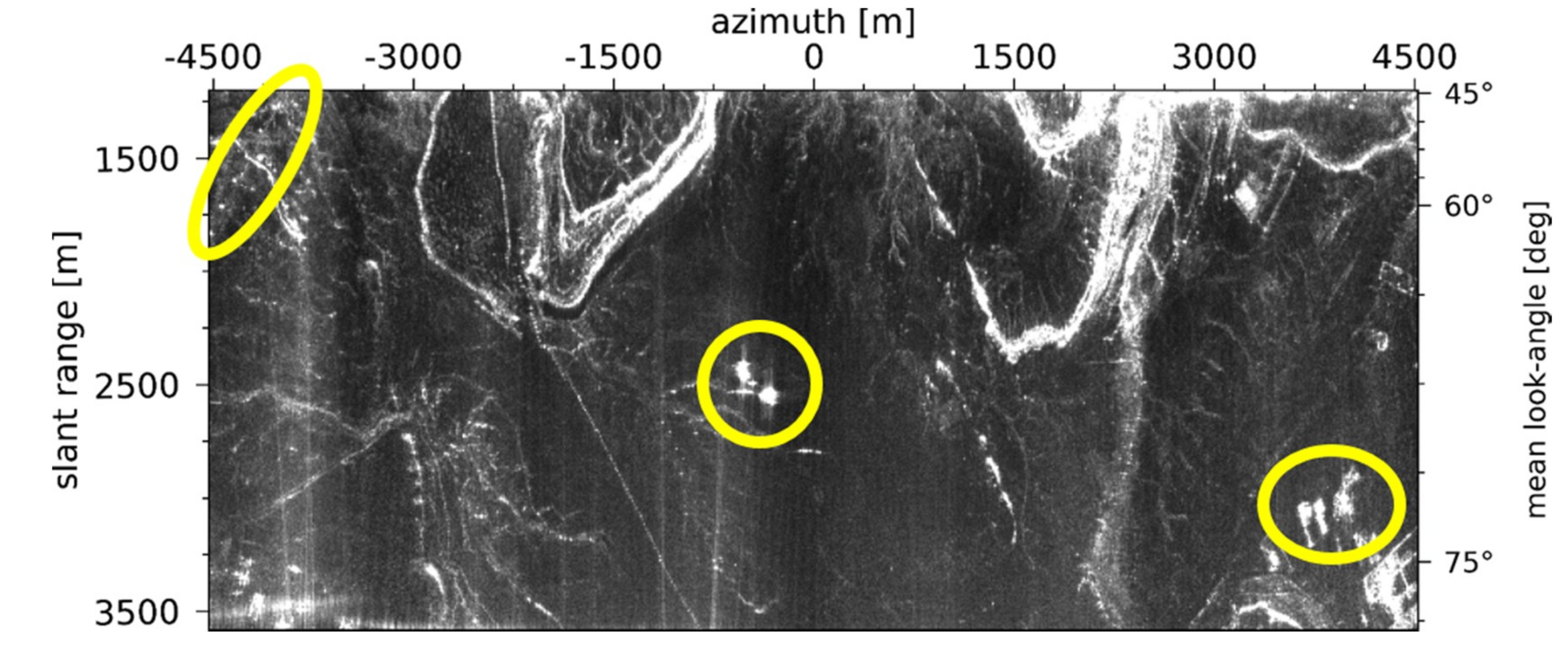
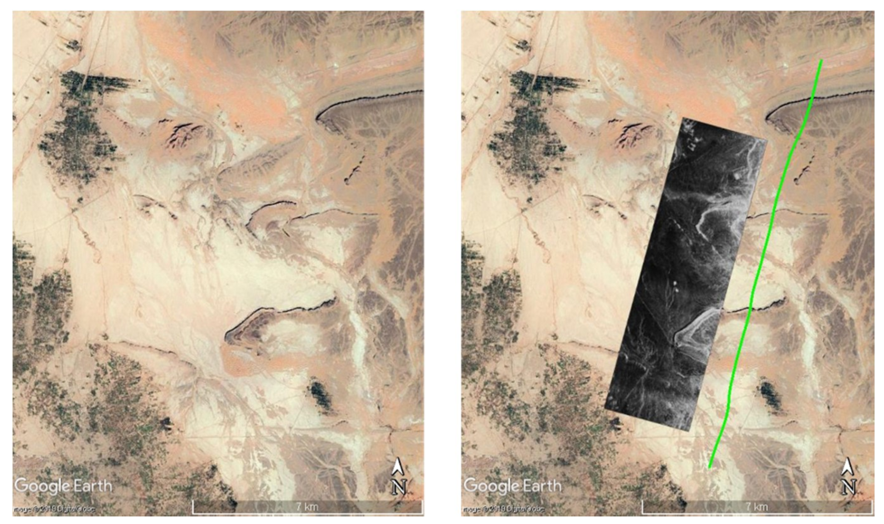
Application of the processing chain depicted in Figure 9 has led to the generation of four focused Single Look Complex (SLC) data, one for each polarimetric channel. Table 2 reports main data processing parameters. Figure 10 shows, in radar grid (that is, range-azimuth), the amplitude of the corresponding Multi Look Complex (MLC) data relevant to the VV channel. In the right vertical axis of the figure it is specified the (mean) look-angle corresponding to the range coordinate reported in the left vertical axis. The observed scene has an extension of about 9 Km in azimuth and 2.5 Km in range. Figure 11 shows the SAR image of Figure 10 in geographic grid and superimposed to a Google Earth orthophoto. The green line represents the flight track projected on the ground. As can be seen in the orthophoto reported in the left panel, the area exhibits an overall flat topography and it can substantially be considered as a rough bare soil.
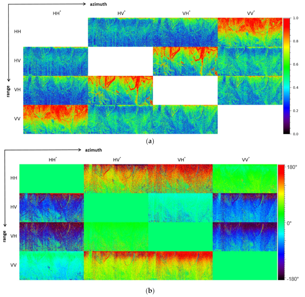
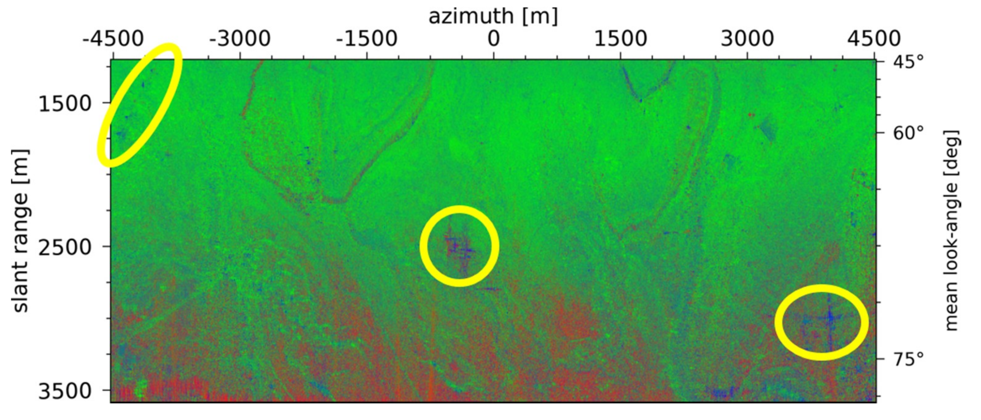
The amplitude and phase of the correlation coefficients between the polarimetric channels are depicted in Figure 12. In particular, see Figure 12a, the amplitude of the co-polar (HH-VV) correlation coefficient assumes quite high values (greater than 0.6) up to a range distance of about 3 Km, corresponding to a mean look-angle of about 70°, while the average phase difference between these channels is very small (approximately π/8), see Figure 12b. From Figure 12a it can be also observed that the amplitude of the average normalized cross-products between the co-polar (HH and VV) and cross-polar (HV and VH) channels is very low, as it happens when the observed targets exhibit reflection symmetry [78]. These results are thus compatible with the scattering behavior expected in the presence of rough bare soil. The presence of rough bare soil, whose dominant scattering mechanism is the surface scattering contribution [78,79], is confirmed also by the results of the obtained Pauli decomposition [78], which is depicted in Figure 13, where the class of the odd-bounce scattering events (the greenish pixels) is strongly dominant up to distances of about 3 Km. Beyond this range, the transmitted waves impinge the surface at grazing incidence (look angles greater than 70°), thus leading to a non-negligible diffuse scattering contribution (the reddish pixels in Figure 13), and to HH and VV returns which are almost completely uncorrelated, see Figure 12a.
Exceptions to the above considerations are represented by some isolated man-made targets which are present in the scene (see, the targets highlighted with the yellow ellipses in Figure 10 and Figure 13). In this case indeed the average phase difference between the HH and VV channels is nearly π, see Figure 12b, and the even-bounce component (the blueish pixels in Figure 13) represents the dominant contribution to the scattering mechanism.
To show the interferometric potentialities of this SAR system, we consider three repeat pass acquisitions carried out over the TS4 site. Few minutes elapsed between the different acquisitions.
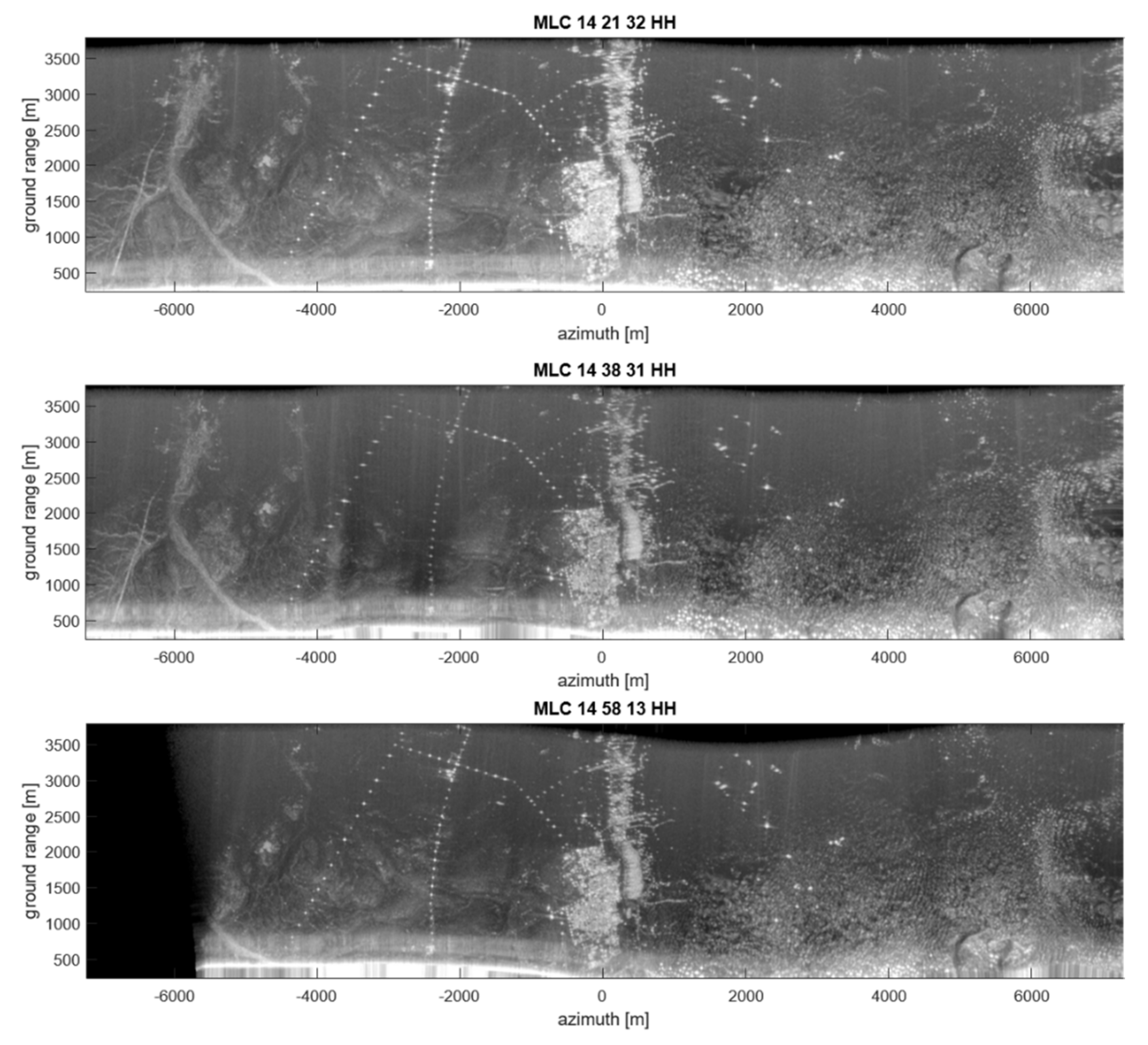
Application of the processing chain depicted in Figure 9 has led to the generation of twelve focused SLC, one for each track and polarimetric channel. Table 3 reports main data processing parameters. As an example, Figure 14 shows, in the ground range-azimuth grid, the amplitude of the corresponding MLC relevant to the HH channel. The observed scene has an extension of about 14 Km in azimuth and 3 Km in (ground) range. Figure 15 shows the SAR image of the top panel of Figure 14 in geographic grid and superimposed to a Google Earth orthophoto.
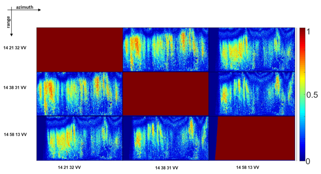
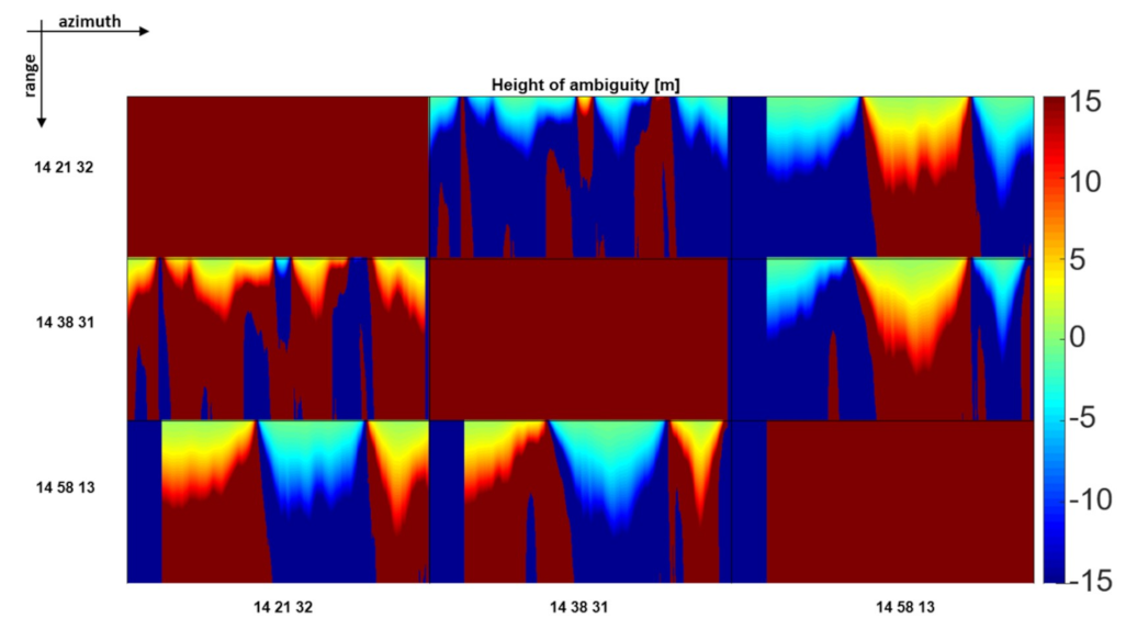
For all the interferometric data pairs achievable with the different polarimetric channels, we have carried out a first interferometric analysis, by using the processing parameters listed in Table 4. In particular, Figure 16 shows the interferometric coherence relevant to the VV channels, which turned out to be on average the highest one with respect to that achievable with the other combinations of polarimetric channels. As can be seen, in most of the observed area the obtained coherence is quite good. Coherence losses are however observed in near range and in some well confined azimuth strips, due to the spatial decorrelation effects induced by the large spatial baselines generated by the severe track deviations of the helicopter during the radar acquisitions. This is confirmed by the height of ambiguity maps reported in Figure 17 and relevant to the same data pairs considered in Figure 16. As can be seen, in the low coherence regions of Figure 16 the height of ambiguity reported in Figure 17 reaches very low (absolute) values. Note in particular, that the color scale in Figure 17 is set between (−15 m, 15 m) to highlight that trajectories are crossing, causing the interferometric baseline to go to 0. Accordingly, at some locations the height of ambiguity becomes infinite (hence all the saturated areas), and then returns in the interval (−15, 15) with opposite sign.
Note also that in some confined range strips (see for instance the central azimuth portion of the 14:58:13–14:38:31 and 14:21:32–14:58:13 interferograms) the coherence is low from near to far range although the (absolute) value of the height of ambiguity is very high (greater than 15 m) between mid and far range, approximately. This is due to the strong attitude variations of the helicopter during the acquisitions. In some portions of the flown tracks it is indeed likely that these effects were significantly different for the different acquisitions, thus reducing the overlapping between the Doppler spectra of the different interferometric channels.
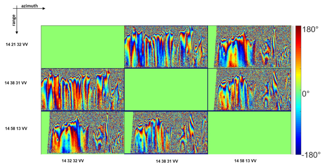
By the way, in the high coherence regions, which represent the large part of the observed area, interferometric fringes are well visible, as it can be seen in Figure 18, where the interferograms relevant to the same data pairs considered in Figure 16 are shown.

6. Conclusions and Further Developments

In this work, we have presented a recently developed aerial imaging radar system operating in the UHF and VHF bands as Sounder and as full polarimetric Synthetic Aperture Radar (SAR). More specifically, three operational modes are possible: Sounder, SAR-Low and SAR-High, each working at a different frequency.
To obtain a first evaluation of the potentialities of the system, a helicopter-borne campaign has been conducted in May 2018 over an arid region located in southeastern Morocco, around the city of Erfoud at the northern edge of the Sahara Desert. Several tracks, covering four different test sites (denoted as TS1, TS2, TS3 and TS4), have been flown by exploiting all the three available radar acquisition modes. From the huge dataset collected during the campaign, we have processed a small subset and presented first results.
In particular, to show the potentialities of the Sounder system, we have presented some representative results relevant to the TS1, TS2 and TS4 sites. To focus the data, we have applied a tomographic reconstruction approach capable to deal with the actually flown flight tracks by exploiting the information provided by the INS-GPS system mounted onboard the helicopter. To check the accuracy of the obtained results, the focused images have been compared to the Sounder-to-ground distance evaluated by exploiting the INS-GPS system and the external SRTM DEM. A good agreement between expected and obtained results has been achieved.
To show the potentialities of the SAR system, we have shown some representative results relevant to the SAR-Low mode data acquired over the TS2 and TS4 sites. More specifically, to focus the data, we have applied a Back Projection approach operating in time domain and capable of exploiting the information provided by the INS-GPS system mounted onboard the helicopter and the external SRTM DEM of the observed area. To show the potentialities of the system related to its full-polarimetric capability, we have considered one radar acquisition carried out over the TS2 site and shown the correlation coefficients between the polarimetric channels as well as the obtained Pauli decomposition. It has been shown that these polarimetric products well match the scattering behavior expected for the observed area (which can substantially be considered as a rough bare soil in the presence of a limited number of well confined man-made targets). To show the interferometric potentialities of the system, we have considered three repeat pass acquisitions carried out over the TS4 site and shown the obtained interferograms along with the corresponding coherence maps. In particular, it has been shown that the obtained interferometric coherence is quite good, but for the near range areas and some well confined azimuth strips, due to the spatial decorrelation effects induced by the large spatial baselines generated by the severe track deviations of the helicopter during the radar acquisitions. By the way, in the high coherence regions, which represent the large part of the observed area, interferometric fringes are well visible.
Summing up, first results relevant to both the Sounder and the SAR modes are promising. Of course, further activities aimed at assessing the full capabilities of the system are planned for the next months.
In particular, full exploitation of the available SAR polarimetric channels in order to obtain added value products such as soil moisture as well as surface roughness maps [80] is matter of current investigation. Beside, acquisition of massive repeat pass interferometric data-sets is planned for the very near future, in order to fully exploit the capabilities of the UHF and VHF bands for the retrieval of the terrain topography below dense forests [81] or the subsurface structure over areas covered by snow/ice [42] through advanced tomographic SAR processing techniques. Moreover, deep interpretation of the nature of subsurface returns visible in the focused Sounder images is subject of investigation and interpretation also aided by electromagnetic simulations of surface clutter. In the meantime, processing of the entire dataset acquired during the Morocco campaign is matter of current study and future work.

Author Contributions

Conceptualization, S.P., F.S., L.B., S.T., G.A., D.C., L.C., G.P., C.P. and G.S.; Methodology, S.P., F.S., L.B., S.T. and G.A.; Software and Validation, P.B., I.C., C.E., G.G., G.L., A.N., C.N., E.D., C.G., S.T. and M.M.d.; Formal Analysis, S.P., F.S., L.B., S.T. and G.A.; Investigation, S.P., F.S., L.B., S.T., G.A., P.B., I.C., C.E., G.G., G.L., A.N., C.N., E.D.., C.G., S.T. and M.M.d.; Data Curation, D.C., L.C., G.P., C.P., G.S., P.B., I.C., C.E., G.G., G.L., A.N., C.N., E.D., C.G., S.T. and M.M.d.; Writing-Original Draft Preparation, S.P.; Supervision, S.P., F.S., L.B., S.T., G.A., R.L. and F.R.; Project Administration, C.F., R.F., F.L. and G.P.; Funding Acquisition, R.L., L.B., F.R. and G.A.

Funding

The work has been partly funded by the Italian Space Agency under the contract N. 2015-029-I.0 “Evoluzione tecnologica e sperimentazione, tramite piattaforma aerea, di un sensore Radar nelle bande VHF e UHF (frequenze inferiori ad 1 GHz)”.

Acknowledgments

The authors thank the anonymous reviewers for their comments and suggestions.

Conflicts of Interest

The authors declare no conflict of interest.

References

  1. Tsang, L.; Kong, J.A.; Shin, R.T. Theory of Microwave Remote Sensing, 1st ed.; Wiley-Interscience: Hoboken, NJ, USA, 1985. [Google Scholar]
  2. Massonnet, D.; Briole, P.; Arnaud, A. Deflation of Mount Etna monitored by spaceborne radar interferometry. Nature 1995, 375, 567–570. [Google Scholar] [CrossRef]
  3. Lanari, R.; Berardino, P.; Bonano, M.; Casu, F.; Manconi, A.; Manunta, M.; Manzo, M.; Pepe, A.; Pepe, S.; Sansosti, E.; et al. Surface displacements associated with the L’Aquila 2009 Mw 6.3 earthquake (central Italy): New evidence from SBAS-DInSAR time series analysis. Geophys. Res. Lett. 2010, 37, L20309. [Google Scholar] [CrossRef]
  4. Lavecchia, G.; Castaldo, R.; de Nardis, R.; de Novellis, V.; Ferrarini, F.; Pepe, S.; Brozzetti, F.; Solaro, G.; Cirillo, D.; Bonano, M.; et al. Ground deformation and source geometry of the 24 August 2016 Amatrice earthquake (Central Italy) investigated through analytical and numerical modeling of DInSAR measurements and structural-geological data. Geophys. Res. Lett. 2016, 43, 12–389. [Google Scholar] [CrossRef]
  5. Kim, D.-J.; Hensley, S.; Yun, S.-H.; Neumann, M. Detection of Durable and Permanent Changes in Urban Areas Using Multitemporal Polarimetric UAVSAR Data. IEEE Geosci. Remote Sens. Lett. 2016, 13, 267–271. [Google Scholar] [CrossRef]
  6. Horn, R.; Nottensteiner, A.; Scheiber, R. F-SAR—DLR’s advanced airborne SAR system onboard DO228. In Proceedings of the 7th European Conference on Synthetic Aperture Radar, Friedrichshafen, Germany, 2–5 June 2008. [Google Scholar]
  7. Baqué, R.; Bonin, G.; du Plessis, O.R. The airborne SAR-system: SETHI airborne microwave remote sensing imaging system. In Proceedings of the 7th European Conference on Synthetic Aperture Radar, Friedrichshafen, Germany, 2–5 June 2008. [Google Scholar]
  8. Perna, S.; Esposito, C.; Amaral, T.; Berardino, P.; Jackson, G.; Moreira, J.; Pauciullo, A.; Vaz Junior, E.; Wimmer, C.; Lanari, R. The InSAeS4 airborne X-band interferometric SAR system: A first assesment on its imaging and topographic mapping capabilities. Remote Sens. 2016, 8, 40. [Google Scholar] [CrossRef]
  9. Aguasca, A.; Acevo-Herrera, R.; Broquetas, A.; Mallorqui, J.J.; Fabregas, X. ARBRES: Light-Weight CW/FM SAR Sensors for Small UAVs. Sensors 2013, 13, 3204–3216. [Google Scholar] [CrossRef] [PubMed] [Green Version]
  10. Daniels, D.J. Ground Penetrating Radar; John Wiley & Sons: Hoboken, NJ, USA, 2005. [Google Scholar]
  11. Tarchi, D.; Casagli, N.; Fanti, R.; Leva, D.D.; Luzi, G.; Pasuto, A.; Pieraccini, M.; Silvano, S. Landslide monitoring by using ground-based SAR interferometry: An example of application to the Tessina landslide in Italy. Eng. Geol. 2003, 68, 15–30. [Google Scholar] [CrossRef]
  12. Virelli, M.; Coletta, A.; Battagliere, M.L. ASI COSMO-SkyMed: Mission Overview and Data Exploitation. IEEE Geosci. Remote Sens. Mag. 2014, 2, 64–66. [Google Scholar] [CrossRef]
  13. Krieger, G.; Moreira, A.; Fiedler, H.; Hajnsek, I.; Werner, M.; Younis, M.; Zink, M. TanDEM-X: A Satellite Formation for High-Resolution SAR Interferometry. IEEE Trans. Geosci. Remote Sens. 2007, 45, 3317–3341. [Google Scholar] [CrossRef] [Green Version]
  14. Torres, R.; Snoeij, P.; Geudtner, D.; Bibby, D.; Davidson, M.; Attema, E.; Potin, P.; Rommen, B.; Floury, N.; Brown, M.; et al. GMES Sentinel-1 Mission. Remote Sens. Environ. 2012, 120, 9–24. [Google Scholar] [CrossRef]
  15. Seu, R.; Biccari, D.; Orosei, R.; Lorenzoni, L.V.; Phillips, R.J.; Marinangeli, L.; Picardi, G.; Masdea, A.; Zampolini, E. SHARAD: The MRO 2005 shallow radar. Plane. Space Sci. 2004, 52, 157–166. [Google Scholar] [CrossRef]
  16. Croci, R.; Seu, R.; Flamini, E.; Russo, E. The SHAllow RADar (SHARAD) onboard the NASA MRO mission. Proc. IEEE 2011, 99, 794–807. [Google Scholar] [CrossRef]
  17. Picardi, G.; Plaut, J.J.; Biccari, D.; Bombaci, O.; Calabrese, D.; Cartacci, M.; Cicchetti, A.; Clifford, S.M.; Edenhofer, P.; Farrell, W.M.; et al. Radar soundings of the subsurface of Mars. Science 2005, 310, 1925–1928. [Google Scholar] [CrossRef]
  18. Jordan, R.; Picardi, G.; Plaut, J.; Wheeler, K.; Kirchner, D.; Safaeinili, A.; Johnson, W.; Seu, R.; Calabrese, D.; Zampolini, E.; et al. The Mars express MARSIS sounder instrument. Plane. Space Sci. 2009, 57, 1975–1986. [Google Scholar] [CrossRef]
  19. Ono, T.; Kumamoto, A.; Nakagawa, H.; Yamaguchi, Y.; Oshigami, S.; Yamaji, A.; Kobayashi, T.; Kasahara, Y.; Oya, H. Lunar radar sounder observations of subsurface layers under the nearside maria of the Moon. Science 2009, 323, 909–912. [Google Scholar] [CrossRef]
  20. Cook, J.C. Proposed monocycle-pulse very-high-frequency radar for airborne ice and snow measurement. Trans. Am. Inst. Electr. Eng. Part I Commun. Electron. 1960, 79, 588–594. [Google Scholar]
  21. Bailey, J.; Evans, S.; Robin, G.D.Q. Radio echo sounding of polar ice sheets. Nature 1964, 204, 420–421. [Google Scholar] [CrossRef]
  22. Hodge, S.M.; Wright, D.; Bradley, J.; Jacobel, R.; Skou, N.; Vaughn, B. Determination of the surface and bed topography in central Greenland. J. Glaciol. 1990, 36, 17–30. [Google Scholar] [CrossRef]
  23. Gogineni, S.; Chuah, T.; Allen, C.; Jezek, K.; Moore, R.K. An improved coherent radar depth sounder. J. Glaciol. 1998, 44, 659–669. [Google Scholar] [CrossRef] [Green Version]
  24. Rodriguez-Morales, F.; Gogineni, S.; Leuschen, C.J.; Paden, J.D.; Li, J.; Lewis, C.C.; Panzer, B.; Alvestegui, D.G.-G.; Patel, A.; Byers, K.; et al. Advanced multifrequency radar instrumentation for polar research. IEEE Trans. Geosci. Remote Sens. 2014, 52, 2824–2842. [Google Scholar] [CrossRef]
  25. Li, J.; Paden, J.; Leuschen, C.; Rodriguez-Morales, F.; Hale, R.D.; Arnold, E.J.; Crowe, R.; Gomez-Garcia, D.; Gogineni, P. High-altitude radar measurements of ice thickness over the Antarctic and Greenland ice sheets as a part of operation ice bridge. IEEE Trans. Geosci. Remote Sens. 2013, 50, 742–754. [Google Scholar] [CrossRef]
  26. Hélière, F.; Lin, C.; Corr, H.; Vaughan, D. Radio echo sounding of Pine Island Glacier, West Antarctica: Aperture synthesis processing and analysis of feasibility from space. IEEE Trans. Geosci. Remote Sens. 2007, 45, 2573–2582. [Google Scholar] [CrossRef]
  27. Kristensen, D.J.; Krozer, S.S.; Hernández, V.; Vidkjær, C.C.; Kusk, J.; Christensen, E.L. ESA’s polarimetric airborne radar ice sounder (POLARIS): Design and first results. IET Radar Sonar Navig. 2010, 4, 488–496. [Google Scholar]
  28. Heggy, E.; Rosen, P.A.; Beatty, R.; Freeman, T.; Gim, Y. Orbiting Arid Subsurface and Ice Sheet Sounder (OASIS): Exploring desert aquifers and polar ice sheets and their role in current and paleo-climate evolution. In Proceedings of the IEEE International Geoscience and Remote Sensing Symposium, Melbourne, Australia, 21–26 July 2013. [Google Scholar]
  29. Bradford, J.H.; Dickins, D.F.; Brandvik, P.J. Assessing the potential to detect oil spills in and under snow using airborne ground-penetrating radar. Geophysics 2010, 75, G1–G12. [Google Scholar] [CrossRef] [Green Version]
  30. Rignot, E.; Mouginot, J.; Larsen, C.F.; Gim, Y.; Kirchner, D. Low-frequency radar sounding of temperate ice masses in Southern Alaska. Geophys. Res. Lett. 2013, 40, 5399–5405. [Google Scholar] [CrossRef] [Green Version]
  31. Mouginot, J.; Rignot, E.; Gim, Y.; Kirchner, D.; Le Meur, F. Low-frequency radar sounding of ice in East Antarctica and southern Greenland. Ann. Glaciol. 2014, 55, 138–146. [Google Scholar] [CrossRef] [Green Version]
  32. Davis, M.E. Foliage Penetration Radar—Detection and Characterization of Objects under Trees; SciTech Publishing: Raleigh, NC, USA, 2011. [Google Scholar]
  33. Moussally, G.; Breiter, K.; Rolig, J. Wide-area landmine survey and detection system. In Proceedings of the 10th International Conference on Ground Penetrating Radar, Delft, The Netherlands, 21–24 June 2004. [Google Scholar]
  34. Le Toan, T.; Quegan, S.; Davidson, M.W.J.; Balzter, H.; Paillou, P.; Papathanassiou, K.; Plummer, S.; Rocca, F.; Saatchi, S.; Shugart, H.; et al. The BIOMASS mission: Mapping global forest biomass to better understand the terrestrial carbon cycle. Remote Sens. Environ. 2011, 115, 2850–2860. [Google Scholar] [CrossRef] [Green Version]
  35. Neumann, M.; Saatchi, S.S.; Ulander, L.; Franson, J. Assessing Performance of L- and P-Band Polarimetric Interferometric SAR Data in Estimating Boreal Forest Above-Ground Biomass. IEEE Trans. Geosci. Remote Sens. 2012, 50, 714–726. [Google Scholar] [CrossRef]
  36. Hoekman, D.H.; Quiriones, M.J. Land cover type and biomass classification using AirSAR data for evaluation of monitoring scenarios in the Colombian Amazon. IEEE Trans. Geosci. Remote Sens. 2000, 38, 685–696. [Google Scholar] [CrossRef]
  37. Garestier, F.; Dubois-Fernandez, P.; Guyon, D.; Le Toan, T. Forest Biophysical Parameter Estimation Using L and P band Polarimetric SAR data. IEEE Trans. Geosci. Remote Sens. 2009, 47, 3379–3388. [Google Scholar] [CrossRef]
  38. Hajnsek, I.; Kugler, F.; Lee, S.K.; Papathanassiou, K.P. Tropical-Forest-Parameter Estimation by Means of Pol-InSAR: The INDREX-II Campaign. IEEE Trans. Geosci. Remote Sens. 2009, 47, 481–493. [Google Scholar] [CrossRef] [Green Version]
  39. Rott, H.; Davis, R.E. Multifrequency and polarimetric SAR observations on Alpine glaciers. Ann. Glaciol. 1993, 17, 98–104. [Google Scholar] [CrossRef]
  40. Sharma, J.J.; Hajnsek, I.; Papathanassiou, K.P.; Moireira, A. Polarimetric Decomposition Over Glacier Ice Using Long-Wavelength Airborne PolSAR. IEEE Trans. Geosci. Remote Sens. 2011, 49, 519–535. [Google Scholar] [CrossRef]
  41. Tebaldini, S.; Nagler, T.; Rott, H.; Heilig, H. Imaging the Internal Structure of an Alpine Glacier via L-Band Airborne SAR Tomography. IEEE Trans. Geosci. Remote Sens. 2016, 54, 7197–8009. [Google Scholar] [CrossRef]
  42. Banda, F.; Dall, J.; Tebaldini, S. Single and Multipolarimetric P-Band SAR Tomography of Subsurface Ice Structure. IEEE Trans. Geosci. Remote Sens. 2016, 54, 2832–2845. [Google Scholar] [CrossRef]
  43. Silva, W.F.; Rudorff, B.F.T.; Formaggio, A.R.; Paradella, W.R.; Mura, J.C. Discrimination of agricultural crops in a tropical semi-arid region of Brazil based on L-band polarimetric airborne SAR data. ISPRS J. Photogramm. Remote Sens. 2009, 64, 458–463. [Google Scholar] [CrossRef]
  44. Lee, J.S.; Grunes, M.R.; Pottier, E.; Ferro-Famil, L. Unsupervised terrain classification preserving polarimetric scattering characteristics. IEEE Trans. Geosci. Remote Sens. 2004, 42, 722–731. [Google Scholar]
  45. Alpers, W.; Holt, B.; Zeng, K. Oil spill detection by imaging radars: Challenges and pitfalls. Remote Sens. Environ. 2007, 201, 133–147. [Google Scholar] [CrossRef]
  46. Rombach, M.; Fernandes, A.C.; Luebeck, D.; Moreira, J. Newest technology of mapping by using airborne interferometric synthetic aperture radar systems. In Proceedings of the IEEE International Geoscience and Remote Sensing Symposium, Toulouse, France, 21–25 July 2003. [Google Scholar]
  47. Papa, C.; Alberti, G.; Salzillo, G.; Palmese, G.; Califano, D.; Ciofaniello, L.; Daniele, M.; Facchinetti, C.; Longo, F.; Formaro, R.; et al. Design and Validation of a Multimode Multifrequency VHF/UHF Airborne Radar. IEEE Geosci. Remote Sens. Lett. 2014, 11, 1260–1264. [Google Scholar] [CrossRef]
  48. Rosa, R.A.S.; Fernandes, D.; Barreto, T.L.M.; Wimmer, C.; Nogueira, J.B. Deforestation detection in Amazon rainforest with multitemporal X-band and p-band sar images using cross-coherences and superpixels. In Proceedings of the IEEE International Geoscience and Remote Sensing Symposium, Fort Worth, TX, USA, 23–28 July 2017. [Google Scholar]
  49. Available online: https://www.geomatics.metasensing.com/airborne-sar (accessed on 20 June 2019).
  50. Wheeler, K.; Hensley, S. The GeoSAR airborne mapping system. In Proceedings of the Record of the IEEE 2000 International Radar Conference, Alexandria, VA, USA, 12 May 2000. [Google Scholar]
  51. Walker, B.; Sander, G.; Thompson, M.; Burns, B.; Fellerhoff, R.; Dubbert, D. A High-Resolution, Four-Band SAR Testbed with Real-Time Image Formation. In Proceedings of the International Geoscience and Remote Sensing Symposium, Lincoln, NE, USA, 31–31 May 1996. [Google Scholar]
  52. Dubois-Fernandez, P.; du Plessis, O.R.; le Coz, D.; Dupas, J.; Vaizan, B.; Dupuis, X.; Cantalloube, H.; Coulombeix, C.; Titin-Schnaider, C.; Dreuillet, P.; et al. The ONERA RAMSES SAR system. In Proceedings of the International Geoscience and Remote Sensing Symposium, Toronto, ON, Canada, 24–28 June 2002. [Google Scholar]
  53. Baqué, R.; Bonin, G.; du Plessis, O.R. The airborne SAR-system: SETHI airborne microwave remote sensing imaging system. In Proceedings of the International Radar Conference “Surveillance for a Safer World”, Bordeaux, France, 12–16 October 2009. [Google Scholar]
  54. Imhoff, M.L.; Johnson, P.; Holford, W.; Hyer, J.; May, L.; Lawrence, W.; Harcombe, P. BioSARTM: An inexpensive airborne VHF multiband SAR system for vegetation biomass measurement. IEEE Trans. Geosci. Remote Sens. 2000, 38, 1458–1462. [Google Scholar] [CrossRef]
  55. Ulander, L.M.H.; Blom, M.; Flood, B.; Follo, P.; Frolind, P.-O.; Gustavsson, A.; Jonsson, T.; Larsson, B.; Murdin, D.; Pettersson, M.; et al. Development of the ultra-wideband LORA SAR operating in the VHF/UHF-band. In Proceedings of the International Geoscience and Remote Sensing Symposium, Toulouse, France, 21–25 July 2003. [Google Scholar]
  56. Zaugg, E.; Edwards, M.; Long, D.; Stringham, C. Developments in compact high-performance synthetic aperture radar systems for use on small Unmanned Aircraft. In Proceedings of the Aerospace Conference, Big Sky, MT, USA, 5–12 March 2011. [Google Scholar]
  57. Dzenkevich, A.V.; Vostrov, E.A.; Mel’nikov, L.J.; Volkov, V.G.; Plyuschev, V.A.; Manakov, V.J. IMARC-multifrequency multipolarization airborne SAR system. In Proceedings of the Radar 97, Edinburgh, UK, 14–16 October 1997. [Google Scholar]
  58. Pinheiro, M.; Reigber, A.; Scheiber, R.; Prats-Iraola, P.; Moreira, A. Generation of highly accurate DEMs over flat areas by means of dual-frequency and dual-baseline airborne SAR interferometry. IEEE Trans. Geosci. Remote Sens. 2018, 56, 4361–4390. [Google Scholar] [CrossRef]
  59. Eisenburger, D.; Krellmann, Y.; Lentz, H.; Triltzsch, G. Stepped-frequency radar system in gating mode: An experiment as a new helicopter-borne GPR system for geological applications. In Proceedings of the IEEE International Geoscience and Remote Sensing Symposium, Boston, MA, USA, 7–11 July 2008. [Google Scholar]
  60. Richards, M.A.; Scheer, J.A.; Holm, W.A. Principles of Modern Radar: Basic Principles; SciTech Publishing: Raleigh, NC, USA, 2010. [Google Scholar]
  61. IEEE Standard Definitions of Terms for Antennas; IEEE Std 145-1983; The Institute of Electrical and Electronics Engineers: New York, NY, USA, 1983.
  62. Moreira, A.; Prats-Iraola, P.; Younis, M.; Krieger, G.; Hajnsek, I.; Papathanassiou, K.P. A tutorial on synthetic aperture radar. IEEE Geosci. Remote Sens. Mag. 2013, 1, 6–43. [Google Scholar] [CrossRef] [Green Version]
  63. Franceschetti, G.; Lanari, R. Synthetic Aperture Radar Processing; CRC PRESS: New York, NY, USA, 1999. [Google Scholar]
  64. Costanzo, S.; Di Massa, G.; Costanzo, A.; Borgia, A.; Papa, C.; Alberti, G.; Salzillo, G.; Palmese, G.; Califano, D.; Ciofanello, L.; et al. Multimode/Multifrequency Low Frequency Airborne Radar Design. J. Electr. Comput. Eng. 2013, 2013, 12. [Google Scholar] [CrossRef]
  65. Richards, M.A. Fundamentals of Radar Signal Processing; Tata McGraw-Hill Education: New York, NY, USA, 2005. [Google Scholar]
  66. Gennarelli, G.; Ludeno, G.; Catapano, I.; Soldovieri, F.; Alberti, G.; Califano, D.; Ciofaniello, L.; Palmese, G.; Papa, C.; Pica, G.; et al. An improved airborne VHF radar sounder for ice and desert exploration. In Proceedings of the 17th International Conference on Ground Penetrating Radar (GPR), Rapperswil, Switzerland, 18–21 June 2018. [Google Scholar]
  67. Chew, W.C. Waves and Fields in Inhomogeneous Media, 2nd ed.; IEEE: New York, NY, USA, 1995. [Google Scholar]
  68. Bertero, M.; Boccacci, P. Introduction to Inverse Problems in Imaging; CRC PRESS: New York, NY, USA, 1998. [Google Scholar]
  69. Persico, R.; Ludeno, G.; Soldovieri, F.; De Coster, A.; Lambot, S. Two-dimensional linear inversion of GPR data with a shifting zoom along observation line. Remote Sens. 2017, 9, 10. [Google Scholar] [CrossRef]
  70. Gennarelli, G.; Catapano, I.; Soldovieri, F. Reconstruction capabilities of down-looking airborne GPRs: The single frequency case. IEEE Trans. Comput. Imaging 2017, 3, 917–927. [Google Scholar] [CrossRef]
  71. Persico, R. Introduction to Ground Penetrating Radar: Inverse Scattering and Data Processing; John Wiley & Sons: Hoboken, NJ, USA, 2014. [Google Scholar]
  72. Moreira, A.; Huang, Y. Airborne SAR Processing of Highly Squinted Data Using a Chirp Scaling Approach with Integrated Motion Compensation. IEEE Trans. Geosci. Remote Sens. 1994, 32, 1029–1040. [Google Scholar] [CrossRef]
  73. Fornaro, G. Trajectory Deviations in Airborne SAR: Analysis and Compensation. IEEE Trans. Aerosp. Electron. Syst. 1999, 35, 997–1009. [Google Scholar] [CrossRef]
  74. Cafforio, C.; Prati, C.; Rocca, F. SAR data focusing using seismic migration techniques. IEEE Trans. Aerosp. Electron. Syst. 1991, 27, 194–207. [Google Scholar] [CrossRef]
  75. Fornaro, G.; Franceschetti, G.; Perna, S. On Center-Beam Approximation in SAR Motion Compensation. IEEE Geosci. Remote Sens. Lett. 2006, 3, 276–280. [Google Scholar] [CrossRef]
  76. Fornaro, G.; Franceschetti, G.; Perna, S. Motion Compensation Errors: Effects on the Accuracy of Airborne SAR Images. IEEE Trans. Aerosp. Electron. Syst. 2005, 41, 1338–1352. [Google Scholar] [CrossRef]
  77. Soumekh, M. Synthetic Aperture Radar Signal Processing with MATLAB Algorithms; Wiley: Hoboken, NJ, USA, 1999. [Google Scholar]
  78. Lee, J.S.; Pottier, E. Polarimetric Radar Imaging: From Basics to Applications; CRC Press: New York, NY, USA, 2009. [Google Scholar]
  79. Van Zyl, J.J. Unsupervised classification of scattering behavior using radar polarimetry data. IEEE Trans. Geosci. Remote Sens. 1989, 27, 36–45. [Google Scholar] [CrossRef]
  80. Iodice, A.; Natale, A.; Riccio, D. Polarimetric Two-Scale Model for Soil Moisture Retrieval via Dual-Pol HH-VV SAR Data. IEEE J. Sel. Top. Appl. Earth Obs. Remote Sens. 2013, 6, 1163–1171. [Google Scholar] [CrossRef]
  81. D’Alessandro, M.M.; Tebaldini, S. Digital Terrain Model Retrieval in Tropical Forests Through P-Band SAR Tomography. IEEE Trans. Geosci. Remote Sens. 2019, 1–8. [Google Scholar] [CrossRef]
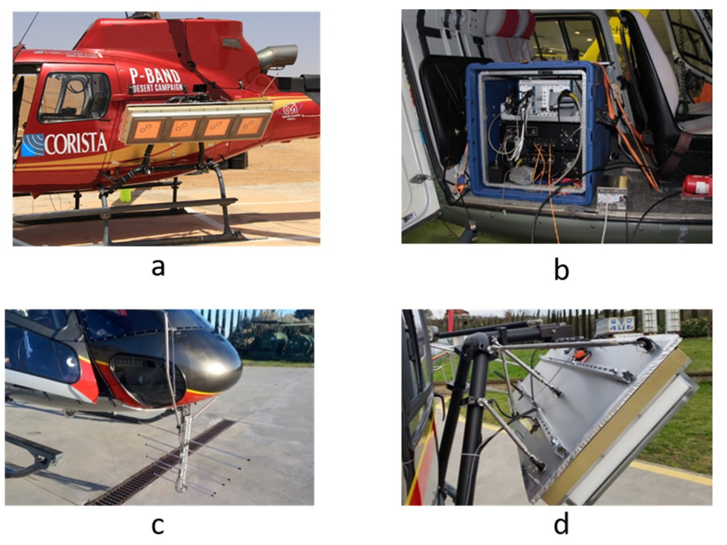
Figure 1. (a) The system ready to flight, (b) radar electronics rack inside the cabin, (c) Sounder antenna, (d) SAR antenna.
Remotesensing 11 01845 g001
Figure 2. Erfoud area, southeastern Morocco. The red, green and blue lines represent the projections on the ground of the flight tracks relevant to the acquisitions carried out with the Sounder, SAR-Low and SAR-High modes, respectively.
Remotesensing 11 01845 g002
Figure 3. Sounder data processing.
Remotesensing 11 01845 g003
Figure 4. Sounder acquisition geometry.
Remotesensing 11 01845 g004
Figure 5. Shifting zoom imaging approach.
Remotesensing 11 01845 g005
Figure 6. Sounder results relevant to one flight track on TS1. Left panel: Google Earth ortophoto including the observed area. Right panel: Corresponding tomographic reconstruction. Mean flight velocity: 45 m/s. Mean flight altitude: 2132 m. Mean terrain height: 930 m.
Remotesensing 11 01845 g006
Figure 7. As for Figure 6, but for TS2. Mean flight velocity: 36 m/sec. Mean flight altitude: 2104 m. Mean terrain height: 770 m.
Remotesensing 11 01845 g007
Figure 8. As for Figure 6 and Figure 7, but for TS4. Mean flight velocity: 45 m/sec. Mean flight altitude: 2081 m. Mean terrain height: 745 m.
Remotesensing 11 01845 g008
Figure 9. SAR data processing.
Remotesensing 11 01845 g009
Figure 10. SAR results, relevant to one flight track on TS2. VV channel. SAR-Low mode. Amplitude of the SAR MLC, in radar grid. Mean flight velocity: 40 m/sec. Mean flight altitude: 1664 m. Mean terrain height: 815 m.
Remotesensing 11 01845 g010
Figure 11. Left panel: Google Earth ortophoto including the observed area. Right panel: As Figure 10, but represented in geographic grid and superimposed to the Google Earth orthophoto of the left panel.
Remotesensing 11 01845 g011
Figure 12. Relevant to the SAR data-set collected by the flight track considered in Figure 10. Correlation coefficients between polarimetric channels: Amplitudes (a) and phases (b).
Remotesensing 11 01845 g012
Figure 13. SAR results relevant to the data-set of Figure 12. Pauli decomposition of the considered scene (red: Volume, green: Surface, blue: Double-bounce).
Remotesensing 11 01845 g013
Figure 14. SAR results relevant to three repeat pass flight tracks on TS4. HH channel, SAR-Low mode: Amplitude of the SAR MLCs in ground range-azimuth grid. Acquisition date: 15 May 2018. Mean flight velocity: 50 m/sec. Mean flight altitude: 1600 m. Mean terrain height: 730 m. From the top to the bottom panel the acquisition start time is: 14:21:32, 14:38:31, 14:58:13.
Remotesensing 11 01845 g014
Figure 15. As the top panel of Figure 10 but represented in geographic grid and superimposed to a Google Earth orthophoto.
Remotesensing 11 01845 g015
Figure 16. Relevant to the repeat pass interferometric SAR data-set collected by the flight tracks considered in Figure 14. Coherence maps relevant to the VV channels.
Remotesensing 11 01845 g016
Figure 17. Height of ambiguity maps relevant to the data pairs considered in Figure 16.
Remotesensing 11 01845 g017
Figure 18. Interferograms relevant to the data pairs considered in Figure 16 and Figure 17.
Remotesensing 11 01845 g018
Table 1. System parameters.
ParametersSounderSAR-LowSAR-High
Carrier frequency165 MHz450 MHz860 MHz
Bandwidth40 MHz40 MHz80 MHz
Frequency steps112–3
PRF500 Hz1000 Hz2000–3000 Hz
Pulse width2 µs2 µs2 µs
ModePulsedPulsedPulsed
Antenna typeLog Periodicarray of microstrip antennasarray of microstrip antennas
Antenna gain7 dBi *11 dBi *17 dBi *
Antenna dimension 8 × 58 × 107 cm10 × 45 × 165 cm10 × 45 × 165 cm
Antenna weight2 Kg15 Kg15 Kg
Nominal elevation pointingNadir45°45°
Nominal azimuth pointingNadir
Range aperture68°75°37°
Azimuth aperture50°20°10°
Range resolution3.8 m (free sp.)3.8 m1.9 m
Azimuth resolution1 m1 m1 m
ADC Sampling frequency200 MHz
Peak power200 W
Power consumption500 W
Rack Weight30 Kg
Rack Dimension50 × 50 × 65 cm
* dBi measures the gain of an antenna with respect to an isotropic radiator.
Table 2. SAR data processing parameters relevant to the results collected in Figure 10, Figure 11, Figure 12 and Figure 13.
ParameterValueParameterValue
Azimuth spacing (SLC)0.64 mRange spacing (SLC)1.5 m
Azimuth resolution (SLC)1 mRange resolution (SLC)5 m
Azimuth spacing (MLC)0.64 mRange spacing (MLC)1.5 m
Azimuth resolution (MLC)7.5 mRange resolution (MLC)12.8 m
Table 3. SAR data processing parameters relevant to the results collected in Figure 14 and Figure 15.
ParameterValueParameterValue
Azimuth spacing (SLC)0.7 mGround range spacing (SLC)5 m
Azimuth resolution (SLC)1 mGround range resolution (SLC)6.25 m
Azimuth spacing (MLC)0.7 mGround range spacing (MLC)5 m
Azimuth resolution (MLC) 7 mGround range resolution (MLC)6.25 m
Table 4. SAR data processing parameters relevant to the InSAR results collected in Figure 16, Figure 17 and Figure 18.
ParameterValueParameterValue
Azimuth spacing 4 mGround range spacing 6.25 m
Azimuth resolution 15 mGround range resolution 15 m