Article

Modelling the Surface of Racing Vessel’s Hull by Laser Scanning and Digital Photogrammetry

1
Institute of Geodesy, Cartography and GIS, Faculty of Mining, Ecology, Process Control and Geotechnologies, Technical University of Košice, Park Komenského 19, 040 01 Košice, Slovakia
2
Faculty of Environmental Engineering, Geomatics and Energy, Kielce University of Technology, al. Tysiąclecia Państwa Polskiego 7, 25-314 Kielce, Poland
3
Progress CAD Engineering, s. r. o., Masarykova 16, 08001 Prešov, Slovakia
*
Author to whom correspondence should be addressed.
Remote Sens. 2019, 11(13), 1526; https://doi.org/10.3390/rs11131526
Submission received: 15 May 2019 / Revised: 20 June 2019 / Accepted: 25 June 2019 / Published: 27 June 2019

Abstract

:
The knowledge of the hull shape and geometry of a racing vessel is one of the most important factors for predicting boat performance. The Offshore Racing Congress (ORC) rating system specifies the calculation parameters of the hydrodynamic forces of boat lift and drag on the basis of input data as the length of waterline while sailing, displacement, wetted surface and the volume distribution along the hull. It is represented by sophisticated calculations for national as well as international events and races. Measurement using a reflectorless total station in a coordinate system defined by the sailboat hull is the most established method approved by the ORC organisation. The determination of these geometric parameters by new, unconventional technologies, which should provide a quicker and more detailed measurement while preserving the quality and accuracy of results necessary for the handicap calculations was our main objective. Geometrical shapes of a cabin sailboat hull were determined by the technology of terrestrial laser scanning and two methods of digital close-range photogrammetry—convergence case of photogrammetry and Structure-from-Motion (SfM) method. High-Definition Surveying (HDS) targets for laser scanning and coded targets for digital photogrammetry were used throughout all methods in order to transform the resulting data into a single local coordinate system. The resulting models were mutually compared by visual, geometrical and statistical comparison. In conclusion, both technologies were considered suitable, however, with various advantages and disadvantages. Nevertheless, although labour intensive, the SfM photogrammetry can be considered the most suitable method if the correct procedures are followed.

Graphical Abstract

1. Introduction

The knowledge of geometry and shape of the vessel’s hull is the most important factor to predict the performance of the vessel. In order for racing vessels of different sizes and characteristics to compete with each other with the same chance of winning, it is necessary to introduce a unified system of, the so-called “rating“ or handicaps. This rating (handicap) corrects the time differences achieved by the individual racing vessels and puts them to one level. Searching for a perfect rating system is as old as a sailing race itself. Sailboats owners, sailors, designers are always trying to find solutions that work alongside the changing design of vessels over time. However, no matter what rating system is currently being used, the ideal rating system should have the following characteristics:
  • fair to all vessels,
  • open, transparent and freely available,
  • have rules that are objective, unbiased and open to new inputs,
  • have ratings that are simple but accurate,
  • have flexible evaluation capabilities for use in different race types,
  • easy to use and understandable,
  • managed locally but globally available [1].
The current Offshore Racing Congress (ORC) rating system (ORC International and ORC Club) uses the IMS system (International Measurement System) as a set of measuring principles and the ORC software to calculate the expected performance of the vessel—VPP (Velocity Prediction Program)—to evaluate vessels with different characteristics, of various sizes and hull shapes, stability and many other different details affecting their theoretical speed [2].
The shape of the hull determines not only the length of waterline while sailing but also displacement, wetted surface and the volume distribution along the hull from which hydrodynamic forces of lift and drag can be computed. There is only one way to deal with these calculations correctly—through the Lines Processing Program (LPP), which calculates all relevant hydrostatic data used by Velocity Prediction Program (VPP—software for calculating the expected performance of vessels). Measurement of the hull is realised to generate the offset file (.OFF), which describes the hull model together with its equipment (mainly the keel and rudder). For the measurement, a measuring instrument approved by the organisation Offshore Racing Congress (ORC) is used or another available measuring instrument that is to produce a list of spatial points in the coordinate system defined as follows (Figure 1):
  • the X-axis—longitudinally with the main axis of the hull (centreline), with 0 at the stem and positive towards the stern,
  • the Y-axis—transversely to 0 in the main axis of the hull and positive to outwards,
  • the Z-axis—vertical with 0 at the waterline and positive upwards.
Currently, there are three methods to determine the geometry of the sailboat hull that are acceptable for creating the offset file [3]:
  • using special electromechanical meters and instruments (classic, old method),
  • by geodesy—a tacheometric method using a total station (current method),
  • based on the data from the sailboat design plans, after approval by ORC.
These methods have the disadvantage that they are either outdated and labour-intensive (1); financially and time-consuming (2); or the necessary data are often not available—in the case of old sailboats without original draft designs or the designer is not willing to provide them (3).
However, in recent years, non-contact surveying technologies—laser scanning and digital photogrammetry—have become more prominent in geodesy, in particular for their speed, accuracy and non-contact data acquisition. Therefore, terrestrial laser scanning (TLS), as well as digital close-range photogrammetry, are potentially suitable technologies for data acquisition in the shipbuilding industry due to these advantages. For example, the work by Reference [4] compares TLS and digital photogrammetry for industrial application of computer-aided design (CAD) and reconstruction of the shape of the entire vessel’s hull or only its essential parts. It states that although TLS might potentially be more powerful thanks to its high resolution, in general, the subsequent data processing and geometric modelling steps are too complex to be performed fully automatically. However, on the other hand, he concludes that photogrammetry also requires a human post-processing step but images can be used not only for the determination of the 3D coordinates but are also an aid in recognition of specific parts and features of the object. In another work by Reference [5], the authors used a TLS point cloud to establish a methodology for determining asymmetries in the vessel’s hull for quality control in manufacturing. The authors point out that when using TLS, it is necessary to take into account the noise that the resulting cloud can contain due to calibration, current environmental conditions, scanned surface properties and so forth, which degrades the scan results without proper adjustment. In other research, Reference [6] used a convergent case of close-range photogrammetry to reconstruct the hull of two vessels of various length and the resulting data to obtain the hydrostatic particulars for the model.
Digital close-range photogrammetry can also be successfully used for the digitization and documentation of maritime heritage or wooden shipwrecks [7,8]; determination of the shape and dimensions of fishing boat hulls by laser measurements and NURBS models [9]; or survey of vessel’s hull floating on the water surface and partially underwater [10,11,12]. Also, similarly for TLS, when low-cost triangulation scanners were used to model vessel’s hull and compared with photogrammetric data [13]; or the data obtained by laser scanning were refined by using appropriate calibration and subsequently used to model precise 3D prototype models [14].
Until now, photogrammetry and terrestrial laser scanning were used for various purposes of modelling and analysis of vessels [15,16,17,18] and others.
The given works signify that both TLS and digital photogrammetry appear to be suitable procedures for modelling the racing vessel’s hull to determine handicaps during races. The purpose of this paper is to point out the use of both technologies to measure the hull of a cabin sailboat; use the obtained data to determine the relevant handicaps; subsequently compare both technologies in terms of their labour-intensity, time and financial demands and accuracy; and assess whether any of these technologies can replace the currently used procedures approved by ORC.

2. Methods of Measurements

2.1. Basic Propositions

  • Objects larger in size, such as cabin sailboat hull, require greater handling space and a sufficient distance from the object to capture its shape.
  • Since the vessel itself should be located outside of the water on a sufficiently rigid structure (trail car, suspension system, supporting structure), the measured surface itself can be less or more covered by this construction, which can lead to the extension of measurement from multiple positions and the subsequent processing of obtained data.
  • The used technology should provide a fast (approximately a few hours), accurate (with accuracy up to 2–3 millimetres) and financially not a very demanding measurement of the sailboat hull, ideally applicable directly in the location of the measured vessel. Manipulation with the necessary equipment should be as simple as possible.
Based on the above, the following technologies (methods) were used to obtain the required data:
  • Terrestrial Laser Scanning (TLS),
  • Convergence case of digital Close-Range Photogrammetry (CRP),
  • Structure-from-Motion (SfM) method of digital CRP.

2.2. Terrestrial Laser Scanning

TLS is a technology based on the measurement by the spatial polar method, in which vertical angles, horizontal angles and slope distances are measured. A point cloud, that is, a set of spatial points with defined XYZ Cartesian coordinates, is the result of laser scanning. At the same time, the value of the intensity of the reflected signal I is assigned to each measured point; and in the case of the use of a digital camera integrated into the instrument (or externally attached), also textural information in the form of RGB values [19].
All laser scanning within this work was realised by the pulse dual-axis laser scanner Leica ScanStation C10, together with the Leica 6” circular tilt & turn targets (Figure 2). The manufacturer guarantees the precision of modelled surface 2 mm, the accuracy of individual measurement 6 mm in position and 4 mm in distance, at 1—50 m distance. All accuracy specifications are one sigma. The scanner range is 134 m at 18% albedo.

2.3. Convergence Case of Digital CRP

Convergence case of photogrammetry can be defined as a multi-image photogrammetric method requiring analytical processing using special photogrammetric software. One if its principles is the fact that axes of images may be in a general position with respect to each other. However, they are usually angled towards the object/surface of interest, with the greatest possible image overlap between images (ideally > 80%), so that the processed object covers the largest possible area of an image. The identification of each point on three or more images is an important requirement, allowing for the detection of gross errors and increasing the accuracy of determination of individual points. From a methodological point of view, it can be defined as a bundle adjustment with a mathematical model of perspective transformation. The convergence case of photogrammetry can be considered as the most precise; however, the most laborious compared to other photogrammetric methods. On the other hand, features like better definition of depth due to the fact that a lower base-to-distance ratio can be achieved (even 1:1); automatic measurement of artificial targets; automatic identification of coded targets; automatic searching of identical points on different images (which increases the efficiency of image processing); can be included among advantages of this method.

2.4. Structure from Motion Photogrammetry

Although the SfM method is nowadays perceived as the most advanced photogrammetric method of automatic image processing, its origin lies in the field of computer vision and visual perception. As far back as the work by Ullman, 1978 [20] addressed the question, “how the three dimensional structure and motion of objects can be inferred from the two dimensional transformations of their projected images when no three dimensional information is conveyed by the individual projections.”
Conventional photogrammetric methods require a 3D position of a set of control points for image processing. These points have to be manually identified and subsequently, the process called “camera-pose estimation“ is used to determine imaging stations. However, the SfM method is based on the estimation of three-dimensional structure from two-dimensional image sequences, which are adherent to the movement of the carrier–digital camera. As in the laser scanning, a point cloud is the result of the whole process. The SfM method works on similar principles as stereophotogrammetry or intersection photogrammetry, that is, a 3D structure can be reconstructed from a series of overlapping and mutually shifted and tilted images. However, it is different from a classic photogrammetry in the fact that the scene geometry, camera stations and its orientation are calculated automatically without necessity of ground control points usage, that is, they are calculated simultaneously using an iterative method of bundle adjustment based on a set of characteristic points automatically selected in a series of multiple overlapping images [21,22,23].
Considering the methodology of image processing and generation of the point cloud, this method is most suitable for matte surfaces (which reflects the incident light only to a minimum) with a sufficiently variable texture [24,25,26]. For surfaces with simple, uniform texture, as well as shiny or transparent surfaces (even partially), the resulting point cloud could be noisy or even “empty.”
However, it should be noted that SfM method is often not considered as a genuine photogrammetric method but more as a “black-box,” since automated steps of processing like automated exterior orientation and 3D point cloud generation can be unclear to the user. One of the reasons is the absence of principles forming the basis of photogrammetry from SfM development. The most characteristic difference between photogrammetry and SfM is just the metric aspect of measurements in the object space, that is, in principle, the SfM does not encompass the full process of metric-quality imaged-based 3D measurement and object reconstruction. If a surveyor would like to encompass the SfM process into a photogrammetric survey, the automated processes can be effectively used but a comprehensive analysis of the achieved results (calibration, estimation of parameters of exterior orientation, dense matching, modelling) should be evaluated [27,28].
For both photogrammetric methods, DSLR Pentax K-5 with lens Pentax SMC DA 15mm f/4 ED AL Limited was used. All images were taken from the tripod using the 12-sec self-timer, ISO 100 and aperture f/13.
The technologies considered for the survey were tested on three objects of cabin sailboats (Figure 3):
  • Saturn 720—a tourist sailboat of the European standard for four to five people (about 7.2 m in length and 2.5 m in width), currently not manufactured;
  • Saturn 24 RC—the successor to the Saturn 720;
  • Saturn 23 GT—the latest product, sports version with retractable keel (length approx. 7.0 m and width 2.5 m).

3. Measurements and Results

All hull measurements of the given sailboats were realised in two stages (based on the results obtained from the first stage). During all the work, also the official ORC measurer was presented, with whom all individual steps were consulted.

3.1. The First Stage

All three sailboats were placed in the exterior on a trailer that is commonly used to carry this type of vessels (Figure 3). Measurements by the selected technologies/methods were realised for two days, with varying cloudiness. Before the measurement itself, twelve 12-bit coded targets in the form of self-adhesive paper (Figure 4) were placed on the hull of the sailboat, for the needs of photogrammetric measurement and subsequent transformation and identification of the individual results into the common required coordinate system (Figure 1). The points defining the main axes of the required coordinate system were targeted by three 20 × 20 mm Leica Retro Reflective Target on the hull (Figure 4). Also, the basic dot targets in the form of self-adhesive paper bands were placed on the hull of the first sailboat (Saturn 720—Figure 3), in predetermined cross-sections through the hull (Figure 4). However, due to the position of the sailboat on the trailer, placing the paper bands at the bottom exactly at the position of selected profiles was considerably more difficult (even impossible in the middle of the hull).
Coordinates of 12-bit coded targets, Leica Retro Reflective Target and survey stations for TLS were determined by the total station Leica TS15 in a local coordinate system. Four of the used 12-bit coded targets, evenly distributed over the hull, were used as ground control points for the transformation to the given coordinate system. In order to validate the overall project accuracy in the reference system (Table 1), the eight remaining targets served as control/check points. Their coordinates from the photogrammetric processing were compared with their coordinates surveyed by the total station so that the given deviations could be used to calculate the overall spatial error.

3.1.1. Saturn 720

Firstly, TLS from three scanning stations (with a various height of the scanner) was realised. A point cloud, containing approx. seven hundred thousand points after filtering outliers and unnecessary parts of the sailboat, was the result. As shown in the figure (Figure 5), the parts covered by the construction of the trailer are missing in the resulting cloud completely.
After TLS of the sailboat, photogrammetric imaging from suitably chosen positions was realised, so that the greatest possible overlap between the images with the convergent imaging axes was achieved. In total, 120 images in the RAW format were captured and subsequently converted to 16-bit TIFF format. The method of field calibration was used in both methods of photogrammetric processing. Within field calibration, calibration parameters (parameters of interior orientation) are determined directly during image processing—along with the determination of parameters of external orientation. However, this procedure does not provide the highest possible accuracy. To get accurately computed calibration parameters (of the interior orientation), it is advised to use a priori calibration of the camera (for example, by imaging a target pattern of a spatial calibration point field form a variety of angles, with subsequent image processing and adjustment of calibration parameters).
For the processing of images by the convergence case of photogrammetry, PhotoModeler Scanner (PMSC) software was used. Of all the acquired images, 28 were selected and processed. The scheme of imaging stations is shown in Figure 6. In total, 524 points were reconstructed using the function of Sub-Pixel Target Mode into the final model (Figure 7). The advantage of this function is that the software automatically determines the centre of the circular target with an accuracy of up to 0.05 pixels. The sub-pixel circular target marker is accurate to 0.05 of a pixel for very high-contrast, low-noise circular targets down to about 1-pixel accuracy for lower-contrast, noisier targets [29]. The statistical results of the processing are shown in Table 1.
Subsequently, the Non-Uniform Rational Bezier Spline (NURBS) surface representing the hull was fitted into these points (Figure 7). However, this model, as can be seen at a glance, showed significant deviations from the actual surface of the modelled hull. Although the accuracy of determination of the spatial position of individual targets was sufficiently high (corresponding to the accuracy of the modelled surface by TLS, stated by the manufacturer) but their density and distribution on the surface of the hull were not sufficient so that the resulting NURBS model could represent the real surface.
In the next step, all 120 images were processed by the SfM method of digital close-range photogrammetry using RealityCapture (RC) software. The result of the processing was a dense point cloud forming the measured hull of the sailboat. The statistical data from the processing are given in Table 1. Using the SfM method, the course of the hull was captured and reconstructed at all, even hardly accessible and visible parts (except for two narrow strips at the positions of the support structure of the trailer). However, again at a glance, the resulting point cloud contained high noise and represented the modelled surface insufficiently (Figure 8).

3.1.2. Saturn 24 RC and Saturn 23 GT

For both other sailboats, the conditions and the measurement procedure were the same. Also, the obtained results were comparable to the first sailboat. However, the results from the SfM processing were significantly different. Due to the nature of the automated processing and the required properties of the imaged surface, as mentioned above, the two remaining sailboats were completely unsuitable for such processing. Both sailboats were newer and therefore the texture of their surface was as a homogeneous bright colour, creating strong reflections. Unlike the first—older sailboat, which had a significantly worn-out surface and therefore lost its shine and gained more distinctive texture (which, in the end, was still not enough to achieve good results)—see Figure 9.
Based on the results from the first stage, it was possible to conclude that these results are insufficient and identify the following problems that we had to deal with.

3.1.3. Issues Encountered

  • Placement of the sailboat—the placement of the measured object on the trailer did not allow sufficient imaging of the lower parts of the hull, especially in its central part. Also, the changing conditions in the exterior created undesirable changes in the surface illumination during the imaging—leading to problems during image orientation by SfM method. On the other hand, the use of some suspension system could increase the financial demands, since not everyone is able to do so, and it would be necessary to physically transfer the measured sailboat and pay for the use of such suspension system for the required time.
  • TLS—during the TLS measurement, the only significant issue was the positioning of suitable scanning stations to minimise the number of stations and maximise the coverage of the hull by the laser beam. The most significant restriction was the placement of the sailboat on the trailer (many obscured parts, too low placement).
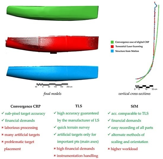
  • The convergent case of CRP—it is clear from the obtained results that convergence case of CRP is the least suitable technology for such modelling of racing vessel’s hull. Although the image processing by convergence CRP provides high precision results and is not very costly, the points of individual cross-sections through the hull cannot be sufficiently well targeted (for example by simple dot targets) due to the size and placement of the object. If the sailboat is placed on a trailer, some parts are obscured and not available for imaging. If the sailboat is hung on a suspension system, the question of the safety is arising regarding the placing of targets on the bottom of the hull.
  • SfM photogrammetry—the SfM photogrammetry provides fast imaging and image processing of obtained images but its biggest issue is a simple, uniform texture of the hull, which, in addition, creates strong reflections in the case of newer and not so worn-out sailboats. For older vessels, this issue should not be so significant. However, the most appropriate methodology of measurement should not be limited by certain types of surface.

3.2. The Second Stage

Based on the problems mentioned above identified during the first stage, the measurement in the second stage was carried out under the following conditions:
  • Of all three sailboats, only one of them was used—Saturn 24RC (logistics reasons + the most common type of hull surface and the most problematic one).
  • The sailboat was moved into the interior from the outside. Since the owner had this sailboat placed in the “out-of-season“ customised building (sheet metal building of hangar-style), it was placed inside it. Moreover, there was also a suspension system adapted to hang the sailboat up to a height of about 1.5 m above the floor using two hanging straps (Figure 10).
  • Due to the fact that the hull of the sailboat is factory-symmetrical by the longitudinal axis (axis X—Figure 1), only one half of the hull was imaged and processed by the SfM photogrammetry, which greatly saved the time of imaging and image processing. Within the TLS, the whole hull was scanned.
  • The convergence case of CRP was assessed as insufficient and inadequate and therefore, no longer used.
  • The points defining the main axes of the required coordinate system were again targeted by Leica Retro Reflective Targets. 12-bit coded targets were used for the transformation of results into the common required coordinate system.
Also, at this stage, the coordinates of 12-bit coded targets, Leica Retro Reflective Targets and scanning stations were determined by measurement using total station Leica TS15 in the local coordinate system.
TLS was realised from six scanning stations. The scanning resolution was set to 5 mm; however, the final resolution was higher (up to 2 mm) on parts of the surface overlapping from adjacent scanning stations. The distance of scanning varied from 0.5 m to 3 m. The RMS of the final registration of individual scans reached 4 mm. On two stations, the laser scanner was placed on a pillar plate of tripod instead of a tripod, so that a sufficient point cloud density covering the entire surface of the hull was achieved (Figure 11). The resulting point cloud covering the whole surface contained approx. 1.7 mil. points.
Within the SfM photogrammetric imaging and processing, it was necessary to deal with the inappropriate texture of the surface in the first place. Due to the placement of the sailboat in the interior and therefore more constant and diffuse illumination, problems with the emergence of strong surface reflections were partially and temporarily eliminated, since the use of pattern projection in the next step created some additional moderate reflections. To suppress the influence of uniform white texture, we decided to use the artificial projection of a suitably chosen texture on the surface to ensure better automated processing by SfM algorithms. Due to the length of the hull, two full HD projectors with sufficient brightness and contrast were placed at both ends and directed so that their field of view covered the entire surface of the measured half part of the hull. Two image files in JPG format containing random wall stone texture were selected as the projected textures (Figure 12).
The imaging itself was realised from a suitably chosen imaging stations so that the best possible overlap between images, together with convergent image axes, was achieved.
However, the main issue that can occur during the illumination of a smooth and relatively shiny surface with a projector (as well as in the case of common artificial lighting, for example, to obtain suitable light conditions during imaging), is the appearance of reflections in oblique images (Figure 13—left). Therefore, only those images were selected during the processing from all the images captured, which did not contain reflections on the surface caused by the projector. This problem could be eliminated by using a polarisation filter. However, even the use of such filter did not sufficiently eliminate all reflections, which could lead to problems with automated image orientation during subsequent software processing (Figure 13—right). Another option would be to use a polarisation filter not only for the lens on the camera but also for the source of light (and therefore reflections), that is, to use polarised light directly to illuminate the measured surface. This, however, could bring some complications to the imaging itself (for example, for a non-professional surveyor/photogrammetrist). However, on the other hand, it could lead to better results of image alignment and subsequent dense image matching.
In total, 139 images in the RAW format were captured and subsequently converted to 16-bit TIFF format. The method of field calibration was also used in this case of SfM processing. The resulting point cloud contained about 2 mils. points. Compared to the SfM processing in the first stage, the average imaging distance was shortened to 3 m (Figure 14), RMS of image orientation reached 0.215 pix, ground-sampling distance 0.45 mm/pix and overall mean spatial error 1.8 mm, therefore, showing better results than in the first stage. However, the time of software processing was extended to 20 h. The resulting point cloud of SfM processing in the second stage was denser, at first glance higher quality, point cloud, capturing the whole surface of the measured half of the hull, without any significant deficiencies; or artefacts due to the texture used during the projection on the hull (therefore, no additional smoothing algorithms had to be used) (Figure 15 and Figure 16).

4. Discussion

Based on the results from the first and second stage, we can state that the convergence case of digital CRP is not a suitable method for this type of object because of its difficulty of processing and the necessity of artificial targeting of characteristic points. Especially with regard to the size and placement of the object, when not all parts of the hull may be accessible, either for the placement of targets or the subsequent imaging. However, in the case of smaller vessels, for example, rowing skiff, this method can provide a quick determination of its shape and dimensions with high accuracy [30].
In contrast, terrestrial laser scanning is a very suitable technology, since we can obtain spatial information about the scanned surface in a short time and with a high density by using a laser scanner with sufficient accuracy. The advantage of this technology is the independence on lighting conditions during the scanning (scanning can be practically realized even in complete darkness) and in the case of racing vessel’s hull (such as cabin sailboats) also the type and texture of the scanned surface (although in the case of transparent or highly reflective surfaces, even the TLS would be unusable). However, the financial demands of this technology over digital photogrammetry is a significant disadvantage.
The SfM method of digital close-range photogrammetry provides, similarly to TLS, a point cloud of high density and while maintaining the optimum imaging conditions and the use of high-quality recording instrument (camera sensor + lens optics), also with high accuracy. In general, digital photogrammetry can provide results with higher accuracy than TLS for shorter imaging/scanning distances and vice versa, the accuracy of TLS will be higher for longer distances. For an object such as a hull of a racing vessel, with a scanning/imaging distance of about 3 m and with the use of the instruments above, both technologies should provide comparable results in terms of accuracy. However, the problem arises with the SfM photogrammetry, since the common imaging and software processing provides unusable results (see the results from the first stage—Figure 6). For that reason, the artificial illumination of the hull with a suitable variable texture and projector with sufficient resolution and contrast was proposed. Thus, imaged surface of the hull and subsequently processed in the same way as in the first stage, provided significantly better results—Figure 15 and Figure 16.
Based on the visual comparison of both resulting models, we can say that both technologies provide comparable results, at first glance. For a more detailed comparison, both models were compared based on their spatial deviations using a difference model. This model was created in the open-source 3D point cloud and mesh processing software CloudCompare 2.10 [31], by using the plugin “M3C2 distance” [32]. This plugin is useful for determining robust signed distances directly between two aligned point clouds (Figure 17).
The difference model shows minimal deviations between the two models; the highest deviations can be found at the edges of the hull and the points of contact of the deck to the hull (Figure 17—highlighted by red colour). These deviations may result from the SfM processing, which was partially affected by the removal of images from oblique positions (due to reflections caused by the projector).
A distribution graph showing the frequency of points and their deviations from the normal distribution, which is represented by the Gaussian curve, is provided in Figure 18. Values of deviations range from −3.7 mm to +3.1 mm, while the mean value of real deviations reached –1 mm, representing a minimum (in our case neglectable) change between the compared data. The distribution of points is sharp; the graph has only one peak, which indicates a low variability of deviations and high frequency of data in a narrow interval.
Based on the given results of both models and their difference model, we can state that both provide similar results in terms of accuracy. It can also be confirmed by the given the accuracy of the used laser scanner guaranteed by the manufacturer (6 mm in position and 4 mm in distance at the scanning distance 1–50 m) and the overall mean spatial error of 4.1 mm calculated from the 8 control points used for the SfM method.
Both of the techniques used in this paper shows that they can provide accurate and reliable results, which can be obtained in a less time-consuming and labour-intensive way than the traditional methods (either classic/old or the current method). Although no similar works are dealing with or proposing, new methods of measurements of racing vessel’s hull instead of the current method by total station, some works with relating issues provide similar results and are consistent with our outcomes. For example, authors in Reference [7] tested TLS and digital photogrammetry to document maritime heritage, with the photogrammetry being the leading technique. They state that photogrammetry provided less accurate results that the laser scanner system used in their work but it is quick and inexpensive. On the other hand, authors in Reference [6] used convergence case of CRP to survey two small boats (length of 0.7 m and 2.5 m) with quite diverse results. While the main directions derived from photogrammetry were consistent with the real dimensions, detailed comparison at locations at fore and aft of the boat showed significant differences between the real and predicted data. The work [13] compared a combination of simple triangulation based laser scanner and digital photogrammetry with a high-accuracy laser radar as a reference data, for boat’s hull modelling. The authors conclude that photogrammetry combined with a laser blade scanning system provide accuracy that is comparable to laser systems one order of magnitude more costly. Finally, the authors in Reference [10] used a bigger boat (approx. 12 m long) placed on a supporting structure, to test digital photogrammetry for the creation of the corresponding DSM in a quick and accurate way, instead of preferred range instruments like laser scanners. The results again showed that even a consumer-grade digital camera can provide fast, cheap and accurate results. However, the existing studies have used either small boats, which can be easily manipulated with and were more suitable for the method of convergence case of photogrammetry or the texture in their case was suitable for automatic image processing; none of which can be guaranteed for every potential racing vessel to be measured and certified by ORC.
Another important point, there are several limitations that we encountered during the presented study. One of the main difficulties were time and space options provided. All individual measurements had to be realised in a relatively short time provided by the owners, together with the various placement of vessels. TLS, together with SfM method, provides relatively quick measurement, so the time should not be an issue in the future. Regarding the placement, the most convenient way is to hang the vessels at a suitable height, or, in the worst case, to use a support structure covering the hull as little as possible (and at a sufficient height). Another limitation is the necessity to use a total station to scale and orient the model obtained by the SfM method to the relevant coordinate system. However, this could be avoided by using alternative methods of scaling—for example, by calibrated photogrammetric scale bars. Another encountered issue was the texture-less surface of some vessels. It did not present a problem for the laser scanner (nor for the convergence case of CRP) but the first results from the SfM method were not further applicable. Therefore, in the second stage, we proposed the application of HD projectors to use a projection of suitable texture directly to the hull, which, ultimately, led to results comparable to TLS.
Additionally, some of these difficulties/limitations have to be taken into account, if one of the used techniques should be adopted as an official measurement technique of racing vessel’s hull. First, the possibility to hang a vessel at a reasonable height may not always be available. Additionally, vessels may be of slightly different construction with varying surface texture, which may result in more (or less) needed projectors and another type of the texture used for projection, in the case of SfM method (see Figure 9). Moreover, sufficient space around the vessel should be considered in order to obtain full coverage of the hull by the artificial texture from projectors.

5. Conclusions

The final comparison (Figure 19 - the convergence case of digital CRP is also considered) shows that both technologies—TLS and SfM provide almost identical results (deviations obtained by the difference model with the mean value 1 mm can be neglected with respect to the required accuracy). The most significant difference is their financial and time requirements. On the one hand, TLS can be financially more demanding but can provide reliable, quick and accurate results (when using, for example, Leica ScanStation C10 laser scanner, which can provide the maximum speed of scanning 50,000 points/s and the accuracy of modelled surface 2 mm). On the other hand, SFM photogrammetry is less expensive but the conditions for obtaining quality results are more demanding. Of course, these two technologies can be considered comparable in terms of accuracy only for shorter imaging/scanning distances—that is, TLS will be more accurate for longer object distance (given the range of the used scanner).
Nevertheless, the SfM photogrammetry seems to be a more suitable technology, despite the higher workload, since it is financially less demanding, provides comparatively accurate results and allows to image and record also hardly accessible parts of the hull (for example, in the case of a vessel placed on a trailer) where the laser scanner could not “see.” Furthermore, additional financial and time savings can be achieved by using alternative methods of scaling and orientation. That is if appropriate targeting of points defining main axes of the required coordinate system is provided, together with using calibrated and certified photogrammetric scale-bars and targets, the corresponding reference coordinate system can be established without the use of the total station and the whole measurement can be realised entirely by photogrammetry. It should be noted that, in this case, there will be no additional data about control points from another measurement system to determine the overall accuracy.
However, there are still questions that should be answered and experiments that should be tested—how to hang the boat in the air the most economically? What type of projector and how many have to be used? What type of texture is the best? Is the difference between TLS and SFM noticeable in the final .OFF file? and so forth.

Author Contributions

Conceptualization, K.P. and K.B.; methodology, K.P. and K.B.; software, Ľ.K.; validation, J.S. and P.R.; formal analysis, K.B.; investigation, K.P., K.B. and Ľ.K.; resources, P.R.; data curation, P.R.; writing—original draft preparation, J.S.; writing—review and editing, J.S. and K.B.; visualization, Ľ.K.; supervision, K.P.; project administration, K.P.; funding acquisition, K.P.

Funding

The study is the result of Grant Project of Ministry of Education of the Slovak Republic VEGA No. 1/0844/18: “Experimental research on the limiting factors of application of non-contact surveying systems for the documentation of specific surfaces for the creation of their digital models”; and KEGA No. 004TUKE-4/2019: “Scientific and educational centre for remote sensing with the focus on the application of e-learning approaches in education.”

Conflicts of Interest

The authors declare no conflict of interest. The funders had no role in the design of the study; in the collection, analyses or interpretation of data; in the writing of the manuscript or in the decision to publish the results.

References

  1. ORC—World Leader in Rating Technology. Available online: http://www.orc.org/ (accessed on 15 November 2017).
  2. ORC Rating System 2019, ORC International and ORC Club. Offshore Racing Congress. 2019. Available online: http://www.orc.org/rules (accessed on 01 May 2019).
  3. Kalatzis, Y. International Measurement System (IMS); Offshore Committee, Hellenic Sailing Federation: Kallithea, Greece, 2012. [Google Scholar]
  4. Koelman, H. Application of a photogrammetry-based system to measure and re-engineer ship hulls and ship parts: An industrial practices-based report. Comput. Aided Des. 2010, 42, 731–743. [Google Scholar] [CrossRef]
  5. Roca-Pardiñas, J.; López-Alvarez, F.; Ordóñez, C.; Menéndez, A.; Bernardo-Sánchez, A. Terrestrial laser scanning used to detect asymmetries in boat hulls. Opt. Eng. 2012, 51, 013605. [Google Scholar] [CrossRef]
  6. Ahmed, Y.; Jamail, A.; Yaakob, O. Boat Survey Using Photogrammetry Method. Int. Rev. Mech. Eng. 2012, 6, 1643–1647. [Google Scholar]
  7. Martorelli, M.; Pensa, C.; Speranza, D. Digital Photogrammetry for Documentation of Maritime Heritage. J. Marit. Archaeol. 2014, 9, 81–93. [Google Scholar] [CrossRef]
  8. Costa, E.; Balletti, C.; Beltrame, C.; Guerra, F.; Vernier, P. Digital Survey Techniques for the Documentation of Wooden Shipwrecks. In Proceedings of the ISPRS—International Archives of the Photogrammetry, Remote Sensing and Spatial Information Sciences, Prague, Czech, 12–19 July 2016; Volume XLI-B5, pp. 237–242. [Google Scholar] [CrossRef]
  9. Kawasaki, J.; Miyoshi, J. Measuring method hull of small fishing boats by using laser telemeter: Considering use of NURBS to draw hull lines. In Proceedings of the 2016 Techno-Ocean, Kobe, Japan, 6–8 October 2016. [Google Scholar] [CrossRef]
  10. Menna, F.; Troisi, S. Photogrammetric 3D modelling of a boat’s hull. In Proceedings of the Optical 3-D Measurement Techniques VIII, Zurich, Switzerland, 9–12 July 2007; pp. 347–354. [Google Scholar]
  11. Menna, F.; Nocerino, E.; Troisi, S.; Remondino, F. A photogrammetric approach to survey floating and semi-submerged objects. Proc. SPIE 2013, 8791, 87910. [Google Scholar] [CrossRef]
  12. Menna, F.; Nocerino, E.; Troisi, S.; Remondino, F. Joint Alignment of Underwater and above-the-Water Photogrammetric 3D Models by Independent Models Adjustment. Int. Arch. Photogramm. Remote Sens. Spatial Inf. Sci. 2015, XL-5/W5, 143–151. [Google Scholar] [CrossRef]
  13. Guidi, G.; Micoli, L.; Russo, M. Boat’s Hull Modeling with Low-Cost Triangulation Scanners. In Proceedings of the Volume 5665 of Electronic Imaging 2005, San Jose, CA, USA, 16–20 January 2015; Volume Videometrics VIII. [Google Scholar] [CrossRef]
  14. Abbas, M.A.; Lichti, D.D.; Chong, A.; Setan, H.; Majid, Z.; Lah, L.C.; Idris, K.M.; Ariff, M.F.M. Improvements to the accuracy of prototype ship models measurement method using terrestrial laser scanner. Measurement 2017, 100, 301–310. [Google Scholar] [CrossRef]
  15. Deparday, J.; Bot, P.; Hauville, F.; Augier, B.; Rabaud, M. Full-scale flying shape measurement of offwind yacht sails with photogrammetry. Ocean. Eng. 2016, 127, 135–143. [Google Scholar] [CrossRef]
  16. Di Paola, F.; Ingrassia, T.; Lo Brutto, M.; Mancuso, A. A reverse engineering approach to measure the deformations of a sailing yacht. Lecture Notes in Mechanical Engineering; Springer: Berlin/Heidelberg, Germany, 2016; pp. 555–563. [Google Scholar] [CrossRef]
  17. Higgs, P. Using Photogrammetry for the Production of Boat Lines. Available online: https://www.woodenboatguildtas.org.au/wp/knowledge/presentation/using-photogrammetry-for-the-production-of-boat-lines/ (accessed on 15 November 2017).
  18. Yaakob, O.; Majid, Z.; Ariff, M.; Idris, K.; Ahmad, B. Measuring Small Boats Using Non-Contact Method. J. Transp. Syst. Eng. 2014, 1, 38–45. [Google Scholar]
  19. Smítka, V.; Štroner, M. 3D scanner point cloud denoising by near points surface fitting. Proc. SPIE 2013, 8791, 87910C. [Google Scholar] [CrossRef]
  20. Ullman, S. The Interpretation of Structure from Motion; Series B. Biological Sciences; The Royal Society of London: London, UK, 1979; Volume 203, pp. 405–426. [Google Scholar] [CrossRef]
  21. Chandran, V.; Elgar, S. Pattern Recognition Using Invariants Defined From Higher Order Spectra—One Dimensional Inputs. IEEE T. Signal Proces. 1993, 41, 205–212. [Google Scholar] [CrossRef]
  22. Snavely, N.; Seitz, S.; Szeliski, R. Modeling the World from Internet Photo Collections. Int. J. Comput. Vis. 2007, 80, 189–210. [Google Scholar] [CrossRef] [Green Version]
  23. Westoby, M.; Brasington, J.; Glasser, N.; Hambrey, M.; Reynolds, J. ‘Structure-from-Motion’ photogrammetry: A low-cost, effective tool for geoscience applications. Geomorphology 2012, 179, 300–314. [Google Scholar] [CrossRef]
  24. Blišťan, P.; Kovanič, Ľ.; Zelizňáková, V.; Palková, J. Using UAV photogrammetry to document rock outcrops. Acta Montan. Slovaca 2016, 21, 154–161. [Google Scholar]
  25. Urban, R.; Štroner, M.; Křemen, T.; Braun, J.; Möser, M. A novel approach to estimate systematic and random error of terrain derived from UAVs: A case study from a post-mining site. Acta Montan. Slovaca 2018, 23, 325–336. [Google Scholar]
  26. Moudrý, V.; Urban, R.; Štroner, M.; Komárek, J.; Brouček, J.; Prošek, J. Comparison of a commercial and home-assembled fixed-wing UAV for terrain mapping of a post-mining site under leaf-off conditions. Int. J. Remote Sens. 2018, 40, 555–572. [Google Scholar] [CrossRef]
  27. PhotoModeler Technologies. PhotoModeler Scanner (Version 2010). 2010.
  28. Fraser, C. SLAM, SfM and photogrammetry: What’s in a name? In Proceedings of the ISPRS Technical Comission II: Symposium 2018 “Towards Photogrammetry 2020”, Riva del Garda, Italy, 3–7 June 2018. [Google Scholar]
  29. Rinaudo, F. Photogrammetry in Cultural Heritage—Is it only SfM software? In Proceedings of the ISPRS Technical Comission II: Symposium 2018 “Towards Photogrammetry 2020”, Riva del Garda, Italy, 3–7 June 2018. [Google Scholar]
  30. Žiška, J.; Marčiš, M.; Haličková, J.; Fraštia, M. Fotogrametrická rekonštrukcia tvaru skifu. In Telesná výchova, Šport, Výskum na Univerzitách; STU Bratislava: Bratislava, Slovakia, 2010; pp. 196–203. [Google Scholar]
  31. CloudCompare (version 2.10.2 Zephyrus). Available online: http://www.cloudcompare.org/ (accessed on 15 April 2019).
  32. Lague, D.; Brodu, N.; Leroux, J. Accurate 3D comparison of complex topography with terrestrial laser scanner: Application to the Rangitikei canyon (N-Z). ISPRS J. Photogramm. Remote Sens. 2013, 82, 10–26. [Google Scholar] [CrossRef] [Green Version]
Figure 1. Definition of the coordinate system for the hull measurement [3].
Remotesensing 11 01526 g001
Figure 2. Leica ScanStation C10 at the survey station during orientation to 6 inch high definition surveying (HDS) target.
Remotesensing 11 01526 g002
Figure 3. Objects of racing cabin sailboats selected for measurements (from the left—Saturn 720; Saturn 23GT; Saturn 24RC).
Remotesensing 11 01526 g003
Figure 4. Types of the used targets.
Remotesensing 11 01526 g004
Figure 5. Left—positions of the laser scanner; right—the final point cloud.
Remotesensing 11 01526 g005
Figure 6. Scheme for imaging stations selected for the convergence case of digital Close Range Photogrammetry (CRP).
Remotesensing 11 01526 g006
Figure 7. Down - resulting 524 points of processing by convergence case of digital CRP; up—the final Non–Uniform Rational Bezier Spline (NURBS) model.
Remotesensing 11 01526 g007
Figure 8. Up—an overall view of the final point cloud from Structure–from–Motion (SfM) processing; down—a cross-section through the final point cloud with visible noise.
Remotesensing 11 01526 g008
Figure 9. Comparison of the texture of the first sailboat (Saturn 720)—left; and the second one (Saturn 24RC)—right.
Remotesensing 11 01526 g009
Figure 10. Detail of the suspension system using hanging straps for placing the sailboat to the appropriate height.
Remotesensing 11 01526 g010
Figure 11. Up—positions of the laser scanner in the 2nd stage; down—the final point cloud.
Remotesensing 11 01526 g011
Figure 12. Left—the sample texture used during SfM imaging; right—its projection on the hull.
Remotesensing 11 01526 g012
Figure 13. Left—reflections from oblique imaging; right—partial elimination using a polarisation filter.
Remotesensing 11 01526 g013
Figure 14. Imaging stations in the second stage.
Remotesensing 11 01526 g014
Figure 15. Final point cloud from the 2nd measurement by the SfM method.
Remotesensing 11 01526 g015
Figure 16. Left—a portion of the final textured point cloud; right—detailed cross-section.
Remotesensing 11 01526 g016
Figure 17. The difference model between terrestrial laser scanning (TLS) and SfM data; with the highest deviations marked in red areas.
Remotesensing 11 01526 g017
Figure 18. The frequency distribution graph.
Remotesensing 11 01526 g018
Figure 19. The final comparison of methods.
Remotesensing 11 01526 g019
Table 1. Parameters of imaging and image processing by photogrammetric methods.
SfM (RC)CRP (PMSC)
No. of used images12028
Average imaging distances8.5 m
Time of software processing8 h24 h
No. of reconstructed points1.3 mil.524
Ground Sampling Distance1.3 mm/pix
RMS of image orientation0.375 pix0.228 pix
Acc. in the reference system (overall mean spatial error)4.1 mm2.1 mm

