Article

Investigating the Feasibility of Multi-Scan Terrestrial Laser Scanning to Characterize Tree Communities in Southern Boreal Forests

1
School of Forest Sciences, University of Eastern Finland, P.O. Box 111, 80101 Joensuu, Finland
2
Department of Forest Sciences, University of Helsinki, P.O. Box 27, 00014 Helsinki, Finland
3
Department of Remote Sensing and Photogrammetry, Finnish Geospatial Research Institute (National Land Survey of Finland), Geodeetinrinne 2, 02431 Masala, Finland
*
Author to whom correspondence should be addressed.
Remote Sens. 2019, 11(12), 1423; https://doi.org/10.3390/rs11121423
Submission received: 14 May 2019 / Revised: 6 June 2019 / Accepted: 13 June 2019 / Published: 14 June 2019
(This article belongs to the Section Forest Remote Sensing)

Abstract

:
Terrestrial laser scanning (TLS) has proven to accurately represent individual trees, while the use of TLS for plot-level forest characterization has been studied less. We used 91 sample plots to assess the feasibility of TLS in estimating plot-level forest inventory attributes, namely the stem number (N), basal area (G), and volume (V) as well as the basal area weighed mean diameter (Dg) and height (Hg). The effect of the sample plot size was investigated by using different-sized sample plots with a fixed scan set-up to also observe possible differences in the quality of point clouds. The Gini coefficient was used to measure the variation in tree size distribution at the plot-level to investigate the relationship between stand heterogeneity and the performance of the TLS-based method. Higher performances in tree detection and forest attribute estimation were recorded for sample plots with a low degree of tree size variation. The TLS-based approach captured 95% of the variation in Hg and V, 85% of the variation in Dg and G, and 67% of the variation in N. By increasing the sample plot size, the tree detection rate was decreased, and the accuracy of the estimates, especially G and N, decreased. This study emphasizes the feasibility of TLS-based approaches in plot-level forest inventories in varying southern boreal forest conditions.

1. Introduction

Most of the carbon in terrestrial biosphere is stored in forest ecosystems, which are key components in the global carbon cycle and biodiversity maintenance [1,2]. Assessing carbon stores and fluxes in a forest ecosystem requires an understanding of the ecosystem functioning as ecosystem services are end products of various biochemical processes that result when individual plant communities interact with climate and each other. This means that the functionality of plant communities and the functional traits of individual plant species affect ecosystem properties [3,4]. In other words, ecosystem functioning can be characterized through the functionality of its components by investigating the properties of plant communities. In the terrestrial biosphere, trees are among the most important plants, thus having a great impact on a forest ecosystem’s functionality and the provision of ecosystem services [5,6]. Consequently, characterizing the functionality of tree communities by means of forest inventory techniques contributes to an understanding of forest ecosystem functioning.
Methods to acquire forest inventory data have evolved over time alongside the technological development [7,8]. Previously, the acquisition of detailed information on the functional traits of trees and tree communities has solely been based on the use of sample plots from which forest inventory attributes describing tree properties are either manually measured in the field with traditional mensuration tools or estimated with allometric models from the field-measured attributes [9,10]. However, during recent years, terrestrial laser scanning (TLS) has been adopted as the foremost technique to digitize forest stands by providing a detailed three-dimensional reconstruction of trees and tree communities [11,12]. In a TLS-based forest inventory, most of the trees can be detected from TLS point clouds using automatic tree detection algorithms (e.g., [13,14,15,16,17]). Besides providing information on basic tree attributes, such as the diameter at breast height (dbh) and tree height, the use of TLS point clouds enables non-destructive approaches to estimate stem profile and volume [18,19,20,21] as well as to characterize tree crown and branching structure [22], which improve tree biomass modelling [23,24,25,26]. These are major advantages compared to conventional forest inventory methods. In addition to standing trees, TLS can provide information also on downed dead wood [27,28], which is an important structural forest component and a biodiversity indicator in boreal forests [29,30].
Despite the advantages of TLS technology in forest digitation, there are still some factors limiting the applicability of TLS-based approaches in characterizing tree communities. In the international benchmarking study by Liang et al. [12], 18 different methodologies in detecting and characterizing trees from TLS point clouds were compared in varying southern boreal forest conditions to clarify the state-of-the-art and to summarize the past research efforts. The benchmarking revealed that the quality of a point cloud has a significant influence on the results of a TLS-based forest inventory. The greatest challenge is that even with the multi-scan approach, it is still hard to completely and accurately record stems of all trees in a plot due to the occlusion effects of the trees and bushes in forests, which reduces the level of detail that trees can be digitized and, moreover, the level of accuracy that could be reached with the TLS-based approaches. For example, the tree mapping accuracy decreased as the plot complexity level increased. The completeness of tree detection was 70%, 60%, and 30% for easy, medium, and difficult plots, respectively, using single-scan data. With multi-scan data, the completeness level clearly improved, and the respective completeness of tree detection was 90%, 80%, and 50%. The reliability of tree height estimation has been reported to be relatively low (i.e., several meters) when using TLS [12,31]. Nevertheless, it is possible to improve the point cloud quality by acquiring a combined point cloud from multiple scanning positions [8] and by considering the spatial arrangement of the scanners [32,33,34].
If the intention in the future is to use TLS-based forest inventory methods to complement or even replace conventional field measurements, the performance of the new methods should be thoroughly investigated in varying forest conditions. However, the current trend in the past studies regarding the use of TLS in forest inventories has been that the sample plot data used in evaluating the performance of the TLS-based methods have covered only small variations in forest density, or the data have been comprised of only a small number of sample plots (see Table 1). From this perspective, the international benchmarking study by Liang et al. [12] was a significant milestone towards the operational use of TLS-based forest inventory methods. Another issue to be considered is the distinction between tree-level variables and plot-level forest inventory attributes. Most of the previous studies regarding the use of TLS in forest inventories have focused on assessing the performance of TLS-based approaches at the tree-level. However, accurate tree-level attributes do not automatically guarantee accurate plot-level forest characterization if the population captured by TLS is not a representative sample of the whole population. Therefore, the feasibility of TLS to characterize tree communities, in other words, to provide plot-level forest information, needs to be investigated to fill in the knowledge gap. Accurate plot-level forest information on tree communities is needed for forest management and planning purposes, for example, where wall-to-wall estimates for forest inventory attributes are obtained by combining airborne remote sensing materials with ground truth information (e.g., [35]).
The aim of this study is, therefore, to improve the understanding of the feasibility of TLS in characterizing tree communities in diverse forest conditions. In this study, a tree community is defined as a group of trees, represented by a sample plot. The characteristics of a tree community are described by the diameter distribution as well as plot-level forest inventory attributes that are upscaled from the functional and structural traits of individual trees within the community. The forest inventory attributes used in this study are the stem number (N), basal area (G), and total stem volume (V) as well as the basal area weighted mean diameter (Dg) and height (Hg), which are derived automatically from TLS point clouds by using point cloud processing and forest mensuration methods. The effect of the sample plot size with a fixed scan set-up, as well as stand structural heterogeneity, on the estimation accuracy of plot-level forest inventory attributes and tree detection are investigated to strengthen the knowledge of the applicability of point cloud-based methods in forest characterization. Additionally, we discuss the potential effect of the quality of point clouds when the sample plot size varies although the scan set-up is fixed.

2. Materials and Methods

2.1. Study Materials

2.1.1. Study Area

The study area is located in a southern boreal zone in Evo, southern Finland (Figure 1). The forests are characterized by a mixture of managed and natural forests with varying complexity from homogeneous to heterogeneous stands as well as growth stages from young seedling stands to old-growth forests. The tree species composition is also typical for southern boreal forest as dominant tree species are Scots pine (Pinus sylvestris L.), Norway spruce (Picea abies (L.) H. Karst.), and birch (Betula L. sp.). In 2014, 91 sample plots (32 m × 32 m in size) were established to cover the structural variation of forests in the study area (Table 2). The sampling was aided with auxiliary information on forest height and density obtained from a canopy height model based on airborne laser scanning data available (for more details, see [35]).

2.1.2. Terrestrial Laser Scanning Data Acquisition

TLS data were acquired from the sample plots in the spring of 2014. The phase-shift scanners used in the TLS campaign were Leica HDS6100 (Leica Geosystems, St. Gallen, Switzerland) and Faro Focus 3D (Faro Technologies Inc., Lake Mary, FL, USA). The scanner settings were adjusted to ensure point density and point spacing at a 10 m distance from the scanner of approximately 25,000 points/m2 and 6.3 mm, respectively. TLS data acquisition was conducted using a multi-scan approach. In other words, several full field-of-view point clouds were obtained from separate scanning locations. One scan was placed at the plot center (i.e., center scan) and four auxiliary scanning locations (i.e., auxiliary scan) were distributed evenly on quadrant directions (i.e., northeast (45°), southeast (135°), southwest (225°), and northwest (315°)), making five scans per plot in total. A more detailed description of the TLS data acquisition procedure can be found in [12].

2.1.3. Field Inventory

To assess the accuracy and performance of the TLS-based method, a basic suite of forest inventory attributes was obtained by conducting a tree-wise field inventory in the summer of 2014 when all trees with dbh exceeding 5 cm were measured in the field. Details of the field inventory are given in, e.g., [12]. Based on our evaluations, the precision in dbh and tree height measurements in the given forest conditions was approximately 0.3 cm and 0.5 m, respectively [46]. Basal area was computed by considering the cross-sectional area of a tree to be circular. Stem volume was estimated using nationwide species-specific volume equations by Laasasenaho [47], where dbh and tree height were used as explanatory variables. Finally, plot-level forest inventory attributes, in other words, N, G, V, Dg, and Hg, were computed as a sum or basal area-weighed mean of single tree variables according to the following:
N =   n A ,
G = i = 1 n g i A ,
V = i = 1 n v i A ,
D g = i = 1 n d i g i i = 1 n g i ,
H g = i = 1 n h i g i i = 1 n g i ,
where n is the number of trees in a sample plot, A is the area of the sample plot in hectares, gi is the basal area of the ith tree, vi is the stem volume of the ith tree, di is the dbh of the ith tree, and hi is the height for the ith tree.

2.2. Automatic Point Cloud Processing Method to Obtain Plot-Level Forest Characteristics

An automatic point cloud processing method was implemented to obtain the plot-level forest inventory attributes. The method proposed in this study was based on the same principles that are commonly applied when individual trees are detected from multi-scan point clouds and characterized for tree metrics retrieval. In other words, the point cloud is first normalized, and a horizontal point cloud slice is delineated from which cross sections of trees are identified by finding circular or cylindrical point cloud structures [8,12,13,16,48,49]. The detected trees are then delineated from the point cloud for tree metrics extraction where stem dimensions are measured by using circle fitting or cylinder fitting procedures [8,14,16,20,49,50].
The proposed method is a six-stage procedure consisting of: (1) Point cloud normalization, (2) stage-one tree detection, (3) tree-wise point cloud extraction, (4) stage-two tree detection, (5) tree metrics’ extraction, and (6) plot metrics’ extraction. Each stage is described in detail in the following subsections and summarized in Table 3. The workflow was fully implemented in MATLAB (The MathWorks Inc, Natick, Massachusetts, United States) except for the point cloud normalization stage, in which LAStools (rapidlasso GmbH, Gilching, Germany) software [51] was used.

2.2.1. Point Cloud Normalization

The multi-scan point cloud was normalized using the lasground-tool in LAStools (rapidlasso GmbH, Gilching, Germany) software [51]. The points were classified into ground points and non-ground points (i.e., vegetation points), and a digital terrain model (DTM) was generated based on a triangulated irregular network (TIN). Normalization parameters were tuned according to Ritter et al. [43] (see Table 3). Using the DTMs, the point clouds were normalized, and only vegetation points were selected for further analysis to reduce the amount of data to be processed.

2.2.2. Stage-One Tree Detection

The detection of individual trees was based on a filtered and clustered horizontal point cloud slice (Figure 2). First, a horizontal point cloud slice with a height of 0.4 m was delineated from the normalized point cloud at 20 cm below and above the breast height (i.e., 1.3 m above the ground). The point cloud slice was filtered to remove noise and branches by analyzing the point neighborhood. The aim was to obtain points representing the stem surface, and the principle in stem point filtering was similar to the one proposed in [49]. Noise removal was based on the mean distance of a point to its 20 neighbor points, whereas non-stem points were removed by preferring vertical planar surfaces. In the case of branch removal, the point surface was defined by a point and its 80 neighboring points. A normal vector indicating the orientation of each surface was computed, and points with a surface normal vector orientation close to the horizontal direction were proceeded for further processing.
The next step of the stage-one tree detection included segmentation of the filtered points into clusters. It was assumed that points on tree stems have large vertical clusters compared to non-stem points [17]. A cluster was defined as a group of points with a minimum distance of 0.1 m to the nearest cluster. To ensure the clusters represented the cross-sections of trees, a cylinder filtering procedure was applied. The cylinder filtering procedure was based on RANSAC (Random Sample Consensus) cylinder fitting and was similar to the one used in [28]: A cylinder was fitted into points in each cluster, and points on the surface of the fitted cylinder were considered as inliers. Points located outside the cylinder were considered as outliers and removed. The fitted cylinder was forced to be vertical, and the radius of the cylinder was allowed to vary within a prescribed range from 2.5 to 55.0 cm based on a priori knowledge from the field inventory. Vertical cylindrical clusters fulfilling the conditions were considered to represent the cross-sections of trees. Preliminary tree locations were obtained as xy-locations of the cylinders fitted into the points of each cluster.

2.2.3. Tree-Wise Point Cloud Extraction

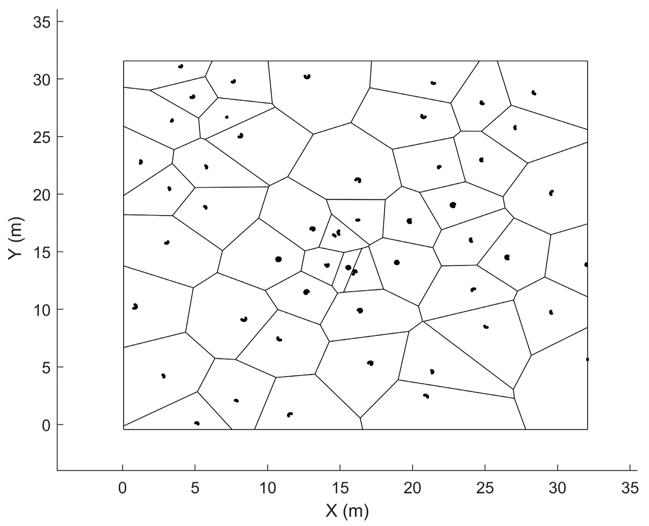
Detected trees were extracted from the original normalized point cloud based on their xy-locations. Using the tree locations as seeds, a Voronoi diagram was established to partition the sample plot into regions that define the closest tree for each point in the original point cloud (Figure 3) as proposed in [16]. The regions were polygonised, and a point-in-polygon approach was applied to extract preliminary tree-wise point clouds.

2.2.4. Stage-Two Tree Detection

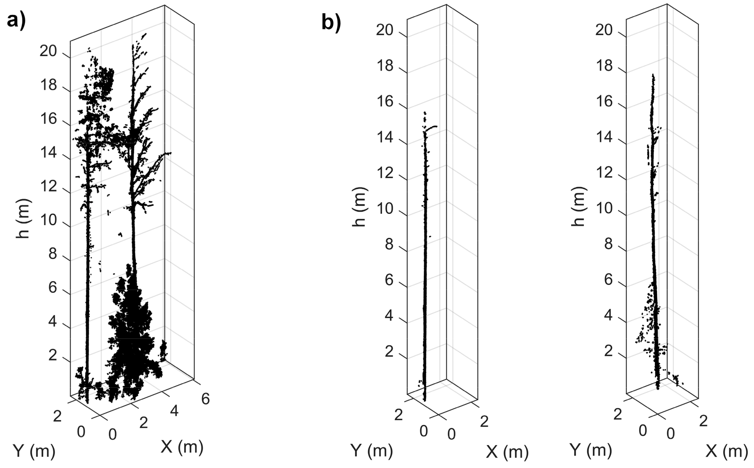
Assuming the stage-one tree detection was not perfect, some trees remained undetected (omission trees) while some tree-like point cloud structures were falsely considered as trees (commission trees). Thus, as the original point cloud was partitioned into regions according to the stage-one tree detection (Figure 3), it was possible that, besides the detected trees and other tree-like point cloud structures, the obtained tree-wise point clouds could also include omission trees. Reorganizing the original point cloud into several smaller units enabled a more thorough investigation of the tree-wise point cloud properties to improve the tree detection, in other words, to remove commission trees and to detect omission trees (Figure 4).
First, the preliminary tree-wise point clouds were filtered to remove points not representing the stem surface that was assumed to be planar and vertical. The stem point filtering procedure was the same that was used in stage-one tree detection (see Section 2.2.2). The filtered point clouds were then segmented into clusters, and properties of the clusters were examined. To be accepted as a tree stem, a set of conditions was set for each cluster: The cluster height had to exceed 4 m in a way that the height of the lowest point in a cluster should be below 0.5 m. In addition, the number of points in a cluster had to exceed 400. These requirements were determined based on a priori knowledge of the tree characteristics in the study area, since most of the living trees measured in the field had a height of 4 m at a minimum. Discarding point cloud clusters with lower heights and relatively small quantities of points aimed to remove undergrowth vegetation, for example (Figure 4).

2.2.5. Tree Metrics Extraction

The retrieval of tree metrics (i.e., dbh, tree height, and stem volume, see Table 3) was based on measurements on the tree-wise point clouds illustrated in Figure 4. Tree height was determined as the height of the highest point in an unfiltered point cloud (Figure 4a) within a radius of 1 m from the realized tree xy-location. For trees in lower canopy layers, the highest points originated from the canopies of adjacent taller trees as stated in [49]. Therefore, the height of the tree top was identified by investigating gaps in the vertical point distribution. If there was a gap, it was assumed that the tree top was reached, and the tree height was computed accordingly.
The taper curve was estimated by measuring diameters along the stem using the filtered point clouds (Figure 4b). Diameters were measured at 20 cm intervals by starting from the breast height (i.e., 1.3 m above the ground) and moving first towards the stump and then upwards to the tree top. Diameter measurement was based on fitting RANSAC-cylinders or circles into point cloud slices that were delineated from each measuring height. RANSAC-cylinder fitting was applied for the first diameter measurement because of the ability of the RANSAC-procedure to find inliers (i.e., stem points) even if the dataset contained outliers (i.e., branch points) that failed to be removed when filtering the point cloud (see Figure 4b). Otherwise, the diameter measurement was based on circle fitting since points for measuring the next diameter were guided by the previous diameter measurement. In other words, once the first diameter was measured, the other diameters could be measured by following the stem surface.
The next step in estimating the taper curve involved filtering the diameter-height observations as well as interpolating missing diameters. First, clear outliers were detected and removed by using an iterative procedure in which the stem was divided into sections, and diameters deviating more than three median absolute deviations from the median diameter of the section were removed. Then, the diameters were compared to the mean of the three previous (or the three closest at the bottom of the stem) diameters as in [50]. A diameter was considered as an outlier, if the relative difference exceeded 10% and 20% for diameters above and below the breast height, respectively. Finally, a cubic spline was fitted to level unevenness in the filtered diameter measurements and to interpolate missing diameters, especially at the top of the tree. The smoothing parameter, p, determining the stage of smoothing was set to 0.5 according to Saarinen et al. [50], where the values of 0.4 to 0.6 for p were found to be suitable. The smoothed taper curve provided diameter–height estimates at 10 cm intervals, which were used to estimate the dbh and stem volume by considering the stem as a sequence of vertical cylinders (i.e., stem sections) using the Huber formula:
V = i = 1 n A m i h i = i = 1 n π h i 16 d i + d i + 1 2 ,
where A m i is the cross-sectional area measured in the middle of the ith stem section, hi is the height of the ith stem section (i.e., 10 cm), n is the total number of stem sections, di is the diameter measured at the butt-end, and di+1 is the diameter measured at the top-end of the ith stem section. An estimate for the total stem volume was calculated as a sum of the volumes of the stem sections. A summary of the work flow and the main techniques for tree metrics extraction is presented in Table 3.

2.2.6. Plot Metrics Extraction

Plot-level forest inventory attributes (i.e., Dg, Hg, N, G, and V) were computed according to the Equations (1)–(5) using the estimates for single tree variables on each sample plot. Dbh distributions describing the structural variation of a forest stand were constructed based on dbh estimates for trees detected from the point clouds.

2.3. Evaluating Accuracy and Performance of the TLS-Based Method

2.3.1. Analyzing the Effect of Sample Plot Size on the Estimation Accuracy of Plot-Level Forest Inventory Attributes

The TLS campaign was designed to obtain high-quality point clouds that enable detailed reconstruction of tree communities. In this context, high quality refers specifically to the minimized occlusion caused by standing trees and undergrowth vegetation as well as enhanced geometrical comprehensiveness, which denotes that trees are scanned from multiple directions. According to Abegg et al. [32], point cloud occlusion can be minimized by placing the scanners evenly on the sample plots with equal distances from the plot borders and between the scanner locations. For this study, the TLS data were acquired accordingly, as one center scan was complemented with four auxiliary scans that were located inside the rectangular sample plot (see Figure 5). However, with this scan set-up, it is evident that trees closer to a plot center are more likely to be scanned from multiple directions than trees near plot borders. This results from the intra-plot variation in the scanning geometry; in other words, how the individual scans are located with respect to trees. This kind set-up is less favorable for trees near plot borders with less perimeter directly visible to the scan locations. Consequently, it was assumed that the point cloud quality issues associated with both occlusion and geometrical comprehensiveness could be minimized by dividing the rectangular sample plots into smaller circular sub-sample plots. The radius of the circular sample plots was set to 11 m to match with the scan set-up being equal to the mean distance between the auxiliary scan locations and plot center. With this arrangement, the auxiliary scans were located approximately at the circumference of the circular plot, ensuring favorable scanning geometry throughout the sample plot (Figure 5).
Use of circular 11-m radius sample plots instead of the rectangular ones was expected to suit better for characterizing tree communities by means of TLS. However, with a fixed scan set-up, the size of the sample plot was assumed to affect the accuracy and performance of the TLS-based approach through the overall point cloud quality. Decreasing the plot radius would intuitively ensure a more uniform scanning geometry throughout the sample plot, but with the cost of a decreased plot size and less intra-plot variation in the forest structure captured. On the other hand, extending the plot radius would be a trade-off between the improved cost-efficiency in data acquisition and increased point cloud occlusion. Thus, to assess the effect of the sample plot size with a fixed scan set-up to the performance of the TLS-based approach in characterizing tree communities, additional circular sub-sample plots with radii of 6 m and 16 m were used alongside the 11-m radius sample plots (Figure 5). Furthermore, the results from the circle plot of various sizes were compared with the original rectangular sample plots of 32 m × 32 m to obtain robust comparison.
The accuracy of the TLS-based approach in characterizing the tree communities was evaluated by comparing the point cloud-derived estimates for plot-level forest inventory attributes (i.e., Dg, Hg, N, G, and V) with the field-measured ones by using the bias and root-mean-square-error (RMSE) as accuracy measures:
bias = i = 1 n X ^ i X i n ,
RMSE = i = 1 n X ^ i X i 2 n ,
where n is the number of sample plots, X ^ i is the TLS-estimate for the plot-level forest inventory attribute for plot i, and Xi is the corresponding attribute based on validation measurements. The effect of the sample plot size on the accuracy and performance of the TLS-based approach was investigated by deriving the estimates for the plot-level forest inventory attributes by also using the additional sample plot sizes (i.e., radii of 6 m and 16 m) and these were compared with the respective accuracy measures of the 11-m radius sample plots. The Student’s t-test was utilized to examine whether the differences in estimation accuracies between the different sample plot sizes were statistically significant. The coefficient of determination (R2) was computed to evaluate the relationship between the measured and estimated forest inventory attributes.

2.3.2. Analyzing the Effect of Stand Heterogeneity on the Estimation Accuracy of Plot-Level Forest Inventory Attributes

As pointed out in previous studies (e.g., [12,32,38]), stand structural heterogeneity affects point cloud quality and thus the reliability of the point cloud-based analysis in a forest environment. To assess the relationship between stand heterogeneity and the performance of the TLS-based approach in characterizing tree communities, an additional plot-level attribute, the Gini coefficient (GC), was computed to describe the stand heterogeneity and structural complexity of the tree communities. The GC is commonly used to compare tree size diversity in different stands [52]. It is based on the dbh distribution and calculated according to the following:
GC = j = 1 n 2 j n 1 g j j = 1 n g j n 1 ,
where n is the number of trees in a sample plot, gj is the basal area of the jth tree, j being the rank of a tree in ascending order from 1, …, n based on the basal area. The GC is a scalar value between 0 and 1, with higher value indicating a more complex forest stand. The effect of stand structural heterogeneity on the accuracy of the TLS-based approach was evaluated by analyzing the errors of the TLS-based estimates for the plot-level forest inventory attributes with respect to the GC. The coefficient of determination (R2) was computed to measure the proportion of variance in the estimation accuracy that is accounted for by stand heterogeneity.

2.3.3. Analyzing Tree Detection Accuracy

When the TLS-based approach was applied, the retrieval of plot-level forest characteristics was based on a single tree inventory. In other words, plot-level forest inventory attributes were computed as a sum or weighed mean of the individual tree attributes (see Equations (1)–(5)). Therefore, the ability of the TLS-based approach to detect individual trees from the point clouds was also investigated to explain the accuracy and performance of the TLS-based approach for deriving plot-level forest characteristics. To assess the tree detection accuracy, trees detected from the point clouds were matched with the reference trees. The closest field-measured tree within a 0.5 m distance was searched for each point cloud-derived tree. If several reference trees were found, the one with a field-measured diameter closest to the corresponding TLS-estimate was considered as the reference. Trees that were detected from the point clouds and matched with the reference trees were classified as correctly detected trees. Point cloud-derived trees with no matching reference trees were classified as falsely detected trees, in other words, commission trees. Reference trees lacking the point cloud-derived correspondent were considered as undetected trees.
Completeness and correctness were used as measures when evaluating the tree detection accuracy at the plot level. Completeness indicates the percentage of trees detected from the point clouds, whereas correctness measures the percentage of point cloud-derived trees that were correctly matched with the reference:
Completeness = n match n ref × 100 % ,
Correctness = n match n TLS × 100 % ,
where nmatch is the number of correctly detected trees, nref is the number of trees measured in the field, and nTLS is the number of trees detected from the point cloud. At the plot level, completeness indicates the tree detection rate, or how large a part of the field-measured N is detected from the point clouds. To consider the properties of the detected trees at the plot level, the completeness of tree detection was also computed with respect to G and V to describe how large a part the detected trees represented of the total basal area and stem volume, respectively. The accuracy measures were compared between the different-sized sample plots to analyze the relationship between the sample plot size and tree detection accuracy. The Student’s t-test was utilized to examine whether the differences in tree detection accuracies between the different sample plot sizes were statistically significant. The effect of stand heterogeneity on tree detection was analyzed by examining the relationship between the accuracy measures and the GC. The coefficient of determination (R2) was computed to evaluate the relationship. In addition, tree size distributions were constructed and compared to assess the representativeness of the point cloud-derived tree community with respect to the field-measured tree community. The distribution mean and standard deviation were computed to facilitate the comparison.

3. Results

3.1. Effect of the Sample Plot Size on the Estimation Accuracy of Plot-Level Forest Inventory Attributes

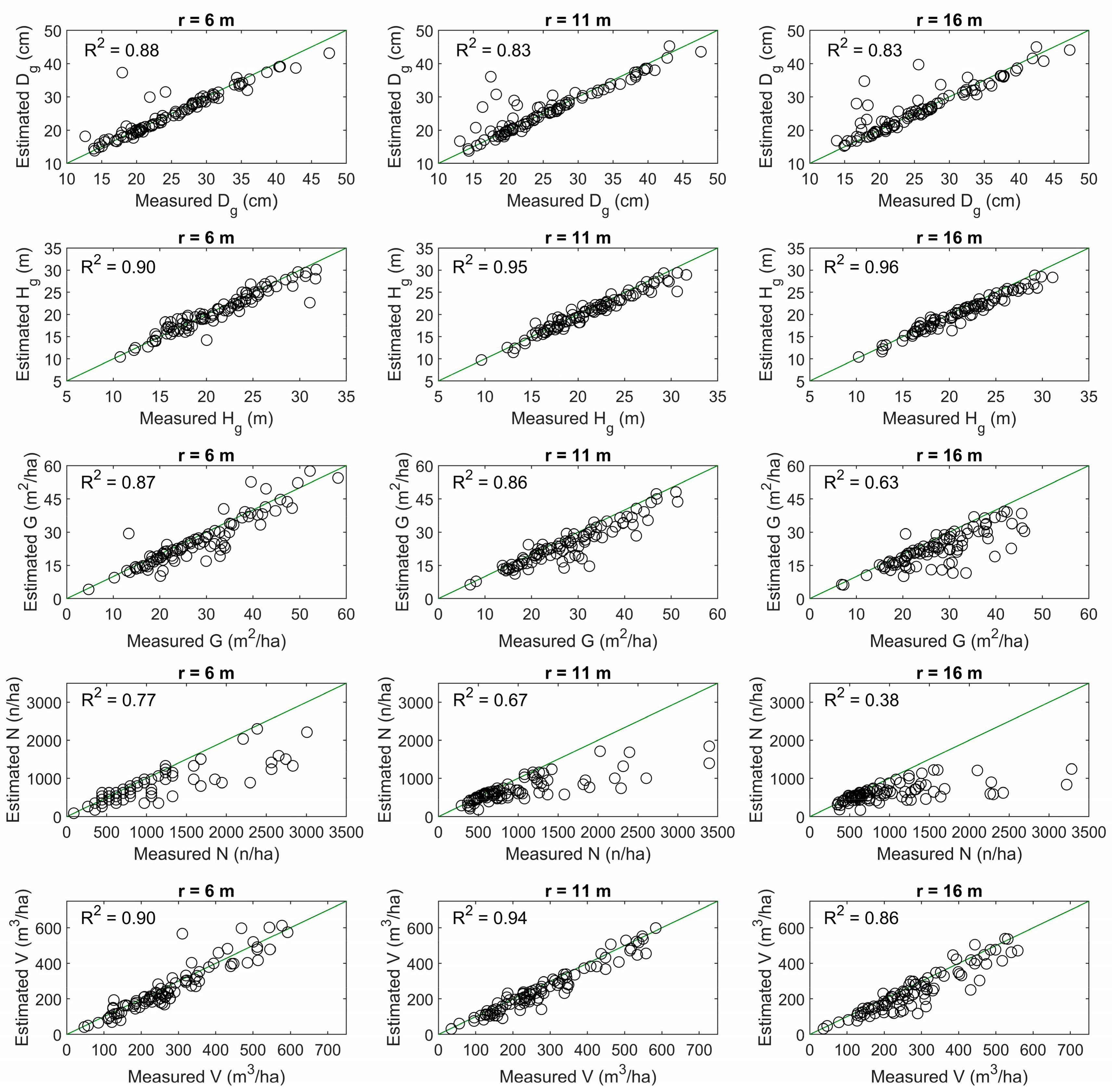
RMSEs in the estimates for forest inventory attributes characterizing the tree communities at the sample plot level were 3.1 cm (12.3%) for Dg, 1.3 m (5.9%) for Hg, 5.1 m2/ha (18.4%) for G, 498 n/ha (51.7%) for N, and 43.1 m3/ha (15.3%) for V, as the sample plot radius was fixed to 11 m to match with the scan set-up (Table 4). The use of TLS point clouds enabled the capture of 83% of the plot-level variation in Dg, 95% in Hg, 86% in G, 67% in N, and 94% in V, respectively (Figure 6). Dg was overestimated by 1.3% while the other attributes were underestimated. The magnitude of bias was reduced when the plot radius was decreased to 6 m, while the corresponding effect on the RMSEs varied with the forest inventory attribute in question (Table 4). A decreased plot size did not significantly (p > 0.05) affect the accuracy of estimating G and N while only a marginal improvement in the estimation accuracy was noticed in case of Dg. The opposite was recorded for Hg and V, in which case the reduced plot size led to a poorer accuracy when compared to the default plot size. Relationships between the measured and estimated forest inventory attributes were somewhat similar when the plot radius was fixed to either 6 or 11 m (Figure 6). Instead, increasing the plot radius from 11 to 16 m resulted in a decreased accuracy when estimating G, N, and V while no significant differences (p > 0.05) between the plot sizes were recorded in case of Dg and Hg (Table 4). Differences in the relationships between the measured and estimated forest inventory attributes were most distinct for the density-related attributes, namely G and N, for which the coefficient of determination (R2) indicated a weaker interrelation when the plot size was increased (Figure 6). Comparison between the results from the original rectangular plots of 32 m × 32 m showed that the circular plots with all sizes provided more reliable estimates for the forest inventory attributes (Table 4).

3.2. Effect of Stand Heterogeneity on Estimation Accuracy of Plot-Level Forest Inventory Attributes

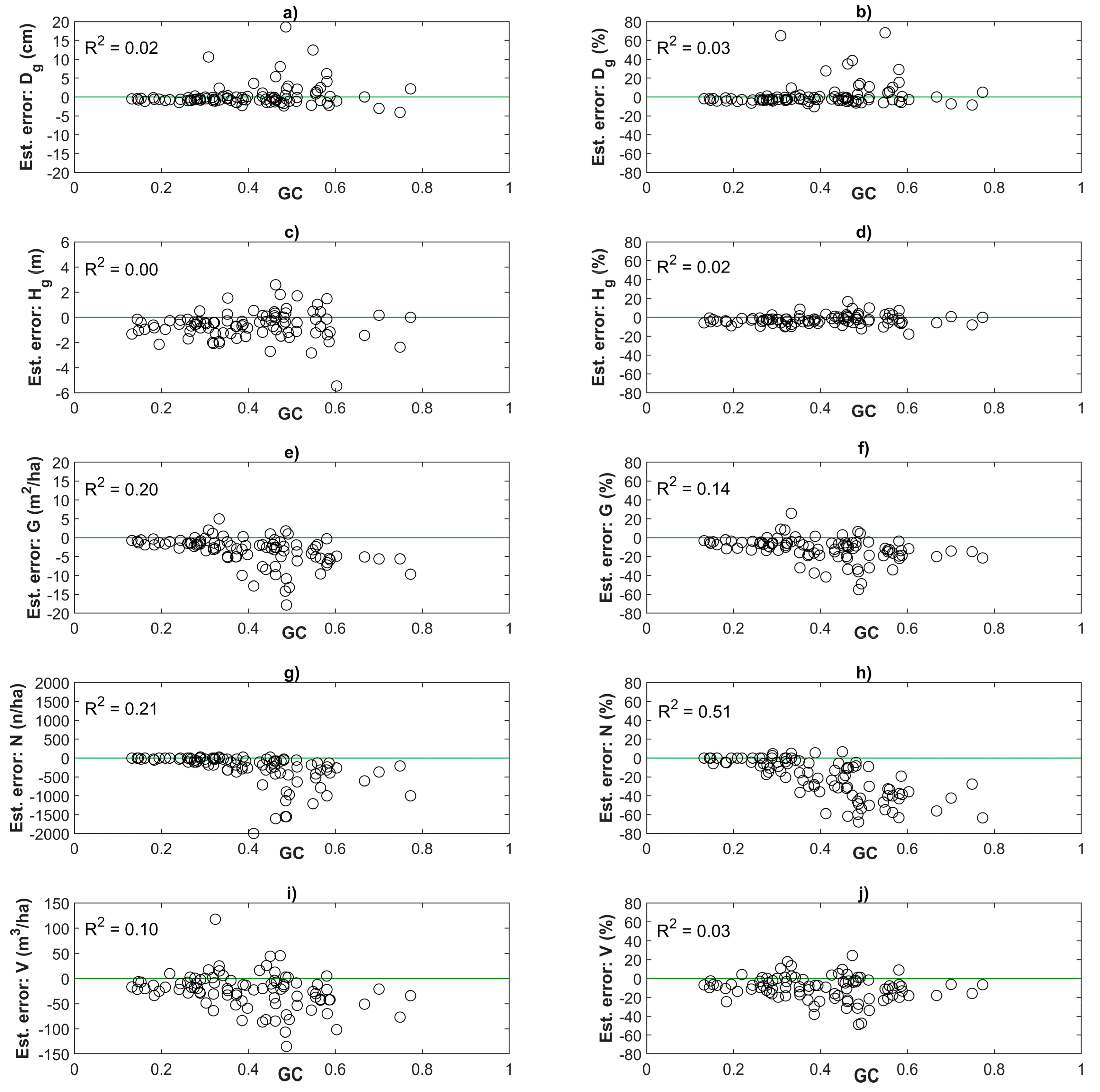
Stand heterogeneity affected the accuracy of estimating density-related forest inventory attributes (i.e., G and N) (Figure 7e–h). GC accounted for 21% and 51% of the variation in absolute and relative errors in the estimates for N, and 20% and 14% of the variation in absolute and relative errors in the estimates for G, respectively. In case of Dg and Hg, the distributions of relative estimation errors were approximately homoscedastic in respect to the stand heterogeneity. The coefficient of determination was close to zero, indicating no trend between the relative estimation error and GC (Figure 7b,d). The same applied also for the relationship between the absolute errors (Figure 7a,c). Instead, the variation of absolute errors in V estimates seemed to slightly vary with GC as an R2 of 0.10 was recorded (Figure 7i). However, no trend between the relative estimation error in V and GC was noticed (Figure 7j).

3.3. Tree Detection Accuracy

A majority of the trees on the sample plots were automatically detected by using the TLS-based approach (Table 5). The overall completeness in detecting N, G, and V were 71.1%, 90.8%, and 93.4%, respectively, as the analyses were based on the smallest sample plots with a radius of 6 m. The overall completeness in detecting N, G, and V slightly decreased when the plot size was enlarged being 57.0%, 80.6%, and 84.1% for the rectangular sample plots. The overall correctness in tree detection remained high at 93.0% to 94.1% regardless of the plot size used (Table 5).
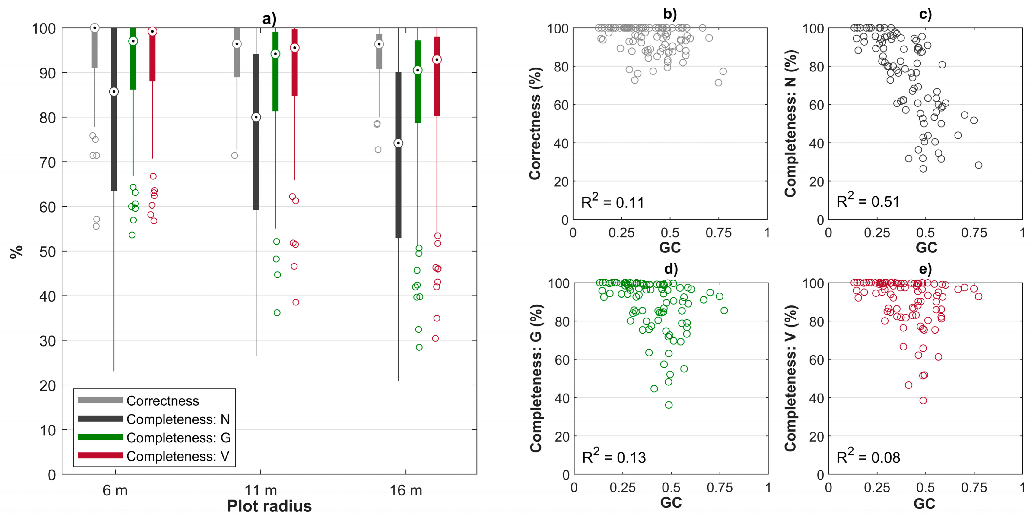
A high level of accuracy in tree detection was achieved for most of the sample plots when the default plot size (i.e., when the plot radius was fixed to 11 m) was used. Over 96% correctness in tree detection and 80%, 94%, and 96% completeness in detecting N, G, and V, respectively, were achieved for 50% of all the sample plots, demonstrating the high performance of the TLS-based approach in favorable forest conditions (Figure 8a). Tree detection was not significantly (p > 0.05) improved when the plot radius was decreased from 11 to 6 m. Instead, a marginal but not statistically significant (p > 0.05) decrease in tree detection accuracy was recorded when the plot radius was increased from 11 to 16 m (Figure 8a).
Variation in the tree detection accuracy between sample plots was explained by stand heterogeneity, which accounted for 51% of the variation in the tree detection rate, or completeness in detecting N (Figure 8c). In case of the other accuracy measures (i.e., correctness in tree detection as well as completeness in detecting G and V), the relationship between stand heterogeneity and tree detection accuracy was not as distinct. However, the variation in tree detection accuracy increased with increasing GC, which indicates that a high performance in tree detection was guaranteed when the TLS-based method was applied on sample plots with a low degree of tree size diversity (Figure 8b–e).
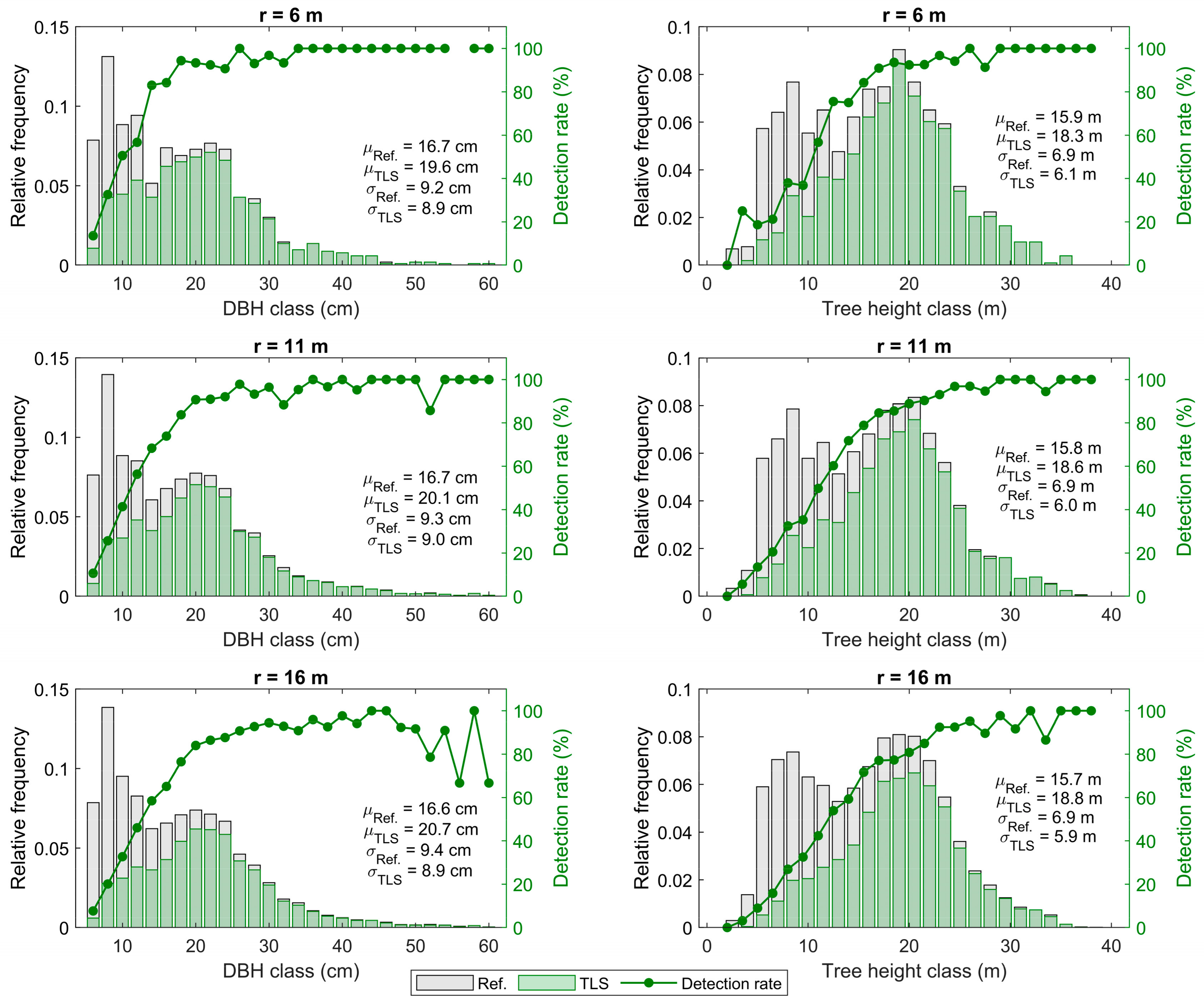
The completeness in detecting N was found to be at a lower level than the completeness in detecting G and V (Table 5, Figure 8). In other words, the group of trees that were detected from the point clouds represented a larger proportion of the total volume and basal area than was expected based on the tree detection rate. This means that large trees were reliably detected while small trees remained under-represented in the group of trees that were detected from the point clouds. The statement was supported by an analysis of the tree detection rate by tree size classes (Figure 9). Trees that were large in both dbh and tree height were detected with a high accuracy regardless of the plot size, while the group of undetected trees consisted mainly of the smallest trees. Since the number of trees in the smallest tree size classes was underestimated, the mean of the point cloud-derived dbh distribution was 2.9 to 4.1 cm higher than the reference. Correspondingly, the mean of the point cloud-derived tree height distribution was 2.4 to 3.1 m higher than the reference depending on the plot size used (Figure 9). Even though a slightly better overall performance in tree detection was recorded when the smallest plot size was used, the differences between the different plot sizes were not considered statistically significant (p > 0.05).

4. Discussion

The objective of this study was to improve the understanding of the feasibility of TLS in characterizing tree communities in diverse southern boreal forest conditions. The TLS-based approach could capture ~95% of the variation in Hg and V, ~85% of the variation in Dg and G, and 67% of the variation in N (Figure 6). On average, Dg was overestimated whereas the other forest inventory attributes were underestimated. To assess the effects of the sample plot size when a fixed scan set-up was used, the radius of the sample plots was increased and decreased by 5 m and the accuracy measures for the 6-m and 16-m radius sample plots were compared with the performance achieved with the default sample plot size. A decrease in the plot size showed no significant effect on the accuracy of the forest inventory attribute estimates or tree detection. However, an increased plot size decreased the tree detection accuracy and the accuracy in estimating G and N (Figure 6). The effect of stand structural heterogeneity on the performance of the TLS-based approach was assessed by investigating the relationship between the GC and the accuracy measures. The GC accounted for 51% of the variation in the tree detection rate and affected the estimation accuracy of G and N (Figure 7 and Figure 8).
Tree detection was found to be the most crucial factor affecting the overall accuracy and performance of the TLS-based approach to characterize tree communities. Out of the total number of 3334 trees on the 91 circular sample plots with a radius of 11 m, 2208 trees (66.2%) were detected from the point clouds, which represented 88.3% of the total basal area and 91.3% of the total volume (Table 5). Tree detection accuracy is interrelated with the accuracy of plot-level forest inventory attributes since the estimates for Dg, Hg, G, N, and V were aggregated from the properties of individual trees that were detected from the sample plot (see Equations (1)–(5)). At the sample plot-level, a failure in tree detection led to a direct underestimation of the density-related attributes, namely N and G. On average, the detected trees were larger in size than the undetected trees, which in turn resulted in an underestimated frequency of small trees in the tree size distributions (Figure 9). Since large trees were overrepresented, the proportion of detected G was at a higher level than the proportion of detected N (Table 5), thus resulting in more reliable plot-level estimates for G rather than N (Table 4). The results of this study regarding the tree detection accuracy are in line with the latest findings on the general performance of TLS-based approaches to detect individual trees from multi-scan point clouds. According to the international benchmarking study by Liang et al. [12], up to about a 90% completeness in tree detection with close to 100% correctness is expected to be reached in favorable forest conditions, with completeness decreasing with increasing stand complexity, which is about 50% for the most heterogeneous boreal forest stands.
Higher performances in tree detection and forest inventory attribute estimation were recorded for sample plots with a low degree of tree size variation (Figure 8). The poorer performance of the TLS-based approach in more heterogeneous stands is explained by increased point cloud occlusion as the standing trees and undergrowth vegetation intercept laser beams, preventing the trees behind them from being scanned. When the stand structure becomes more complex, the total stem number increases with an increased proportion of small trees, which in turn boosts the occlusion effect as the probability of a tree to be shaded by other trees increases [32,33]. The same explanation partly applies to the non-detection of small trees. As seen in Figure 9, the capability of the TLS-based approach to detect small trees was limited. From a methodological point of view, a tree must be sufficiently represented by a point cloud structure to be detected automatically. Small trees have less surface visible to the scanner than larger trees and are thus more likely to be completely occluded by other trees.
Because of the close-range hemispherical scanning geometry, TLS technology is specifically suited for characterizing a horizontal forest structure. Lower parts of tree stems are digitized in detail, enabling accurate dbh measurements where the RMSE typically varies from the sub-centimeter-level to some centimeters in boreal forests (see, e.g., [8,12]). These findings were supported by the results of this study, as the RMSEs in estimating Dg and G were 3.1 cm (12.3%) and 5.1 m2/ha (18.4%), respectively (Table 4). However, from a technological point of view, the upper parts of the tree crowns are often occluded by adjacent trees, which makes it challenging for TLS to capture the top of the tree crown for reliable tree height estimation. Also, as the point spacing increases with the distance to the scanner, the point density naturally decreases towards the top of the tree crown. Therefore, in general, an RMSE of up to several meters can be expected for single tree height estimates [8,12,31]. Nevertheless, this study demonstrates that erroneous individual tree height estimates seem to compensate at the plot-level for an improved accuracy in Hg estimation, for which an overall RMSE of 1.3 m (5.9%) was recorded. This highlights the feasibility of multi-scan TLS to also reliably describe a vertical forest structure, enabling detailed characterization of tree communities.
As expected, the point cloud quality affected the reliability of the TLS-based approach in characterizing tree communities. In this study, different-sized circular sub-sample plots were used to demonstrate different levels of point cloud quality (see Figure 5). The presumed optimal way to acquire high-quality point cloud data was to place the scanners approximately at the circumference of the circular sample plot. This was demonstrated by using sample plots with a radius of 11 m to match with the scan set-up. Decreasing the plot radius to 6 m increased the overall point density by approximately 30% with decreased intra-plot variation in the point cloud quality. However, only marginal, if any, improvement in the overall performance was recorded. Instead, extending the plot radius from 11 to 16 m for improved cost-efficiency in data acquisition decreased the overall point density by approximately 20%. With increased occlusion and decreased geometrical comprehensiveness and overall point density, the performance in tree detection and plot-level forest attribute estimation declined (Table 4 and Table 5). This finding demonstrates the importance of considerations in point cloud data acquisition. It should be kept in mind that, with the given parameters, the proposed TLS-based approach may not produce similar results when applied in forests where the stand structure or growth form of the trees differ from that in boreal forests. However, ensuring geometrical comprehensiveness and minimizing the occlusion effect are key principles when designing the scan set-up to obtain a high-quality terrestrial point cloud for the detailed description of trees and tree communities regardless of the forest structure.

5. Conclusions

This study emphasizes the feasibility of TLS-based approaches in characterizing tree communities by demonstrating a high accuracy in the estimates for plot-level forest inventory attributes for sample plots in varying southern boreal forest conditions. Stand structural complexity correlated negatively with the tree detection rate, which was the most crucial factor affecting the overall performance of the TLS-based forest inventory method. Stand heterogeneity affected tree detection accuracy and thus, the estimation accuracy of TLS-based plot-level forest inventory attributes that measure forest density (i.e., G and N). The use of sample plots with size and geometry matching with the scan set-up provided the best performance for plot-level forest inventories when considering the trade-off between the estimation accuracy and sampling efficiency.
Trees that were not detected from the point clouds were smaller in dimension than detected ones. Compared to large trees, small trees have less stem surface directly visible to the scanner and are thus more prone to occlusion by other trees as the forest density and structural complexity increases. To overcome this challenge, considerations in TLS data acquisition are needed to ensure the retrieval of high-quality point clouds. Based on this study, we recommend that the TLS data for detailed characterization of tree communities in southern boreal forests is collected from circular sample plots using a multi-scan set-up, where one center scan is complemented with several auxiliary scans placed approximately evenly on the circumference of the sample plot. The proposed scanning set-up ensures that the scanning geometry remains favorable throughout the entire sample plot and most of the trees are scanned from multiple directions to minimize occlusion.

Author Contributions

Conceptualization, M.V., M.H., J.H., N.S., V.K., and T.Y.; methodology and formal analysis, T.Y.; writing—original draft preparation, T.Y.; writing—review and editing, M.V., N.S., V.K., and X.L.; supervision, M.V., N.S., and V.K.; project administration and funding acquisition, M.V., M.H., and J.H.

Funding

This research was funded by Academy of Finland through the Centre of Excellence in Laser Scanning Research, grant number 272195.

Acknowledgments

The authors would like to thank Häme University of Applied Sciences for supporting the research activities at the Evo study site.

Conflicts of Interest

The authors declare no conflict of interest.

References

  1. Dixon, R.K.; Brown, S.; Houghton, R.A.; Solomon, A.M.; Trexler, M.C.; Wisniewski, J. Carbon Pools and Flux of Global Forest Ecosystems. Science 1994, 263, 185–190. [Google Scholar] [CrossRef] [PubMed]
  2. Pan, Y.D.; Birdsey, R.A.; Fang, J.Y.; Houghton, R.; Kauppi, P.E.; Kurz, W.A.; Phillips, O.L.; Shvidenko, A.; Lewis, S.L.; Canadell, J.G.; et al. A Large and Persistent Carbon Sink in the World’s Forests. Science 2011, 333, 988–993. [Google Scholar] [CrossRef] [PubMed]
  3. Hooper, D.U.; Chapin, F.S.; Ewel, J.J.; Hector, A.; Inchausti, P.; Lavorel, S.; Lawton, J.H.; Lodge, D.M.; Loreau, M.; Naeem, S.; et al. Effects of biodiversity on ecosystem functioning: A consensus of current knowledge. Ecol. Monogr. 2005, 75, 3–35. [Google Scholar] [CrossRef]
  4. Tilman, D.; Isbell, F.; Cowles, J.M. Biodiversity and Ecosystem Functioning. Annu. Rev. Ecol. Evol. S 2014, 45, 471–493. [Google Scholar] [CrossRef]
  5. Crowther, T.W.; Glick, H.B.; Covey, K.R.; Bettigole, C.; Maynard, D.S.; Thomas, S.M.; Smith, J.R.; Hintler, G.; Duguid, M.C.; Amatulli, G.; et al. Mapping tree density at a global scale. Nature 2015, 525, 201–213. [Google Scholar] [CrossRef] [PubMed]
  6. Asner, G.P.; Martin, R.E.; Knapp, D.E.; Tupayachi, R.; Anderson, C.B.; Sinca, F.; Vaughn, N.R.; Llactayo, W. FOREST CONSERVATION Airborne laser-guided imaging spectroscopy to map forest trait diversity and guide conservation. Science 2017, 355, 385–388. [Google Scholar] [CrossRef] [PubMed]
  7. Dassot, M.; Constant, T.; Fournier, M. The use of terrestrial LiDAR technology in forest science: Application fields, benefits and challenges. Ann. For. Sci. 2011, 68, 959–974. [Google Scholar] [CrossRef]
  8. Liang, X.L.; Kankare, V.; Hyyppa, J.; Wang, Y.S.; Kukko, A.; Haggren, H.; Yu, X.W.; Kaartinen, H.; Jaakkola, A.; Guan, F.Y.; et al. Terrestrial laser scanning in forest inventories. ISPRS J. Photogramm. Remote Sens. 2016, 115, 63–77. [Google Scholar] [CrossRef]
  9. Kangas, A.; Maltamo, M. Forest Inventory: Methodology and Applications; Springer Science & Business Media: Berlin, Germany, 2006; Volume 10. [Google Scholar]
  10. West, P.W. Stand Measurement. In Tree and Forest Measurement; Springer: Berlin, Germany, 2015; pp. 71–95. [Google Scholar]
  11. Newnham, G.J.; Armston, J.D.; Calders, K.; Disney, M.I.; Lovell, J.L.; Schaaf, C.B.; Strahler, A.H.; Danson, F.M. Terrestrial Laser Scanning for Plot-Scale Forest Measurement. Curr. For. Rep. 2015, 1, 239–251. [Google Scholar] [CrossRef] [Green Version]
  12. Liang, X.L.; Hyyppa, J.; Kaartinen, H.; Lehtomaki, M.; Pyorala, J.; Pfeifer, N.; Holopainen, M.; Brolly, G.; Pirotti, F.; Hackenberg, J.; et al. International benchmarking of terrestrial laser scanning approaches for forest inventories. ISPRS J. Photogramm. Remote Sens 2018, 144, 137–179. [Google Scholar] [CrossRef]
  13. Maas, H.G.; Bienert, A.; Scheller, S.; Keane, E. Automatic forest inventory parameter determination from terrestrial laser scanner data. Int. J. Remote Sens. 2008, 29, 1579–1593. [Google Scholar] [CrossRef]
  14. Liang, X.L.; Hyyppa, J. Automatic Stem Mapping by Merging Several Terrestrial Laser Scans at the Feature and Decision Levels. Sensors Basel 2013, 13, 1614–1634. [Google Scholar] [CrossRef] [PubMed] [Green Version]
  15. Heinzel, J.; Huber, M.O. Detecting Tree Stems from Volumetric TLS Data in Forest Environments with Rich Understory. Remote Sens. 2017, 9, 9. [Google Scholar] [CrossRef]
  16. Cabo, C.; Ordonez, C.; Lopez-Sanchez, C.A.; Armesto, J. Automatic dendrometry: Tree detection, tree height and diameter estimation using terrestrial laser scanning. Int. J. Appl. Earth Obs. Geoinf. 2018, 69, 164–174. [Google Scholar] [CrossRef]
  17. Zhang, W.M.; Wan, P.; Wang, T.J.; Cai, S.S.; Chen, Y.M.; Jin, X.L.; Yan, G.J. A Novel Approach for the Detection of Standing Tree Stems from Plot-Level Terrestrial Laser Scanning Data. Remote Sens. 2019, 11, 211. [Google Scholar] [CrossRef]
  18. Liang, X.L.; Kankare, V.; Yu, X.W.; Hyyppa, J.; Holopainen, M. Automated Stem Curve Measurement Using Terrestrial Laser Scanning. IEEE Trans. Geosci. Remote Sens. 2014, 52, 1739–1748. [Google Scholar] [CrossRef]
  19. Olofsson, K.; Holmgren, J. Single Tree Stem Profile Detection Using Terrestrial Laser Scanner Data, Flatness Saliency Features and Curvature Properties. Forests 2016, 7, 207. [Google Scholar] [CrossRef]
  20. Sun, Y.; Liang, X.L.; Liang, Z.Y.; Welham, C.; Li, W.Z. Deriving Merchantable Volume in Poplar through a Localized Tapering Function from Non-Destructive Terrestrial Laser Scanning. Forests 2016, 7, 87. [Google Scholar] [CrossRef]
  21. Pitkanen, T.P.; Raumonen, P.; Kangas, A. Measuring stem diameters with TLS in boreal forests by complementary fitting procedure. ISPRS J. Photogramm. Remote Sens. 2019, 147, 294–306. [Google Scholar] [CrossRef]
  22. Pyörälä, J.; Liang, X.; Saarinen, N.; Kankare, V.; Wang, Y.; Holopainen, M.; Hyyppä, J.; Vastaranta, M. Assessing branching structure for biomass and wood quality estimation using terrestrial laser scanning point clouds. Can. J. Remote Sens. 2018, 44, 1–14. [Google Scholar] [CrossRef]
  23. Kankare, V.; Holopainen, M.; Vastaranta, M.; Puttonen, E.; Yu, X.W.; Hyyppa, J.; Vaaja, M.; Hyyppa, H.; Alho, P. Individual tree biomass estimation using terrestrial laser scanning. ISPRS J. Photogramm. Remote Sens. 2013, 75, 64–75. [Google Scholar] [CrossRef]
  24. Yu, X.W.; Liang, X.L.; Hyyppa, J.; Kankare, V.; Vastaranta, M.; Holopainen, M. Stem biomass estimation based on stem reconstruction from terrestrial laser scanning point clouds. Remote Sens. Lett. 2013, 4, 344–353. [Google Scholar] [CrossRef]
  25. Calders, K.; Newnham, G.; Burt, A.; Murphy, S.; Raumonen, P.; Herold, M.; Culvenor, D.; Avitabile, V.; Disney, M.; Armston, J.; et al. Nondestructive estimates of above-ground biomass using terrestrial laser scanning. Methods Ecol. Evol. 2015, 6, 198–208. [Google Scholar] [CrossRef]
  26. Stovall, A.E.L.; Vorster, A.G.; Anderson, R.S.; Evangelista, P.H.; Shugart, H.H. Non-destructive aboveground biomass estimation of coniferous trees using terrestrial LiDAR. Remote Sens. Environ. 2017, 200, 31–42. [Google Scholar] [CrossRef]
  27. Polewski, P.; Yao, W.; Heurich, M.; Krzystek, P.; Stilla, U. A voting-based statistical cylinder detection framework applied to fallen tree mapping in terrestrial laser scanning point clouds. ISPRS J. Photogramm. Remote Sens. 2017, 129, 118–130. [Google Scholar] [CrossRef]
  28. Yrttimaa, T.; Saarinen, N.; Luoma, V.; Tanhuanpää, T.; Kankare, V.; Liang, X.; Hyyppä, J.; Holopainen, M.; Vastaranta, M. Detecting and characterizing downed dead wood using terrestrial laser scanning. ISPRS J. Photogramm. Remote Sens. 2019, 151, 76–90. [Google Scholar] [CrossRef]
  29. Harmon, M.E.; Franklin, J.F.; Swanson, F.J.; Sollins, P.; Gregory, S.V.; Lattin, J.D.; Anderson, N.H.; Cline, S.P.; Aumen, N.G.; Sedell, J.R.; et al. Ecology of Coarse Woody Debris in Temperate Ecosystems. Adv. Ecol. Res. 1986, 15, 133–302. [Google Scholar] [CrossRef]
  30. Esseen, P.-A.; Ehnström, B.; Ericson, L.; Sjöberg, K. Boreal forests. Ecol. Bull. 1997, 46, 16–47. [Google Scholar]
  31. Wang, Y.S.; Lehtomaki, M.; Liang, X.L.; Pyorala, J.; Kukko, A.; Jaakkola, A.; Liu, J.B.; Feng, Z.Y.; Chen, R.Z.; Hyyppa, J. Is field-measured tree height as reliable as believed A comparison study of tree height estimates from field measurement, airborne laser scanning and terrestrial laser scanning in a boreal forest. ISPRS J. Photogramm. Remote Sens. 2019, 147, 132–145. [Google Scholar] [CrossRef]
  32. Abegg, M.; Kukenbrink, D.; Zell, J.; Schaepman, M.E.; Morsdorf, F. Terrestrial Laser Scanning for Forest Inventories Tree Diameter Distribution and Scanner Location Impact on Occlusion. Forests 2017, 8, 184. [Google Scholar] [CrossRef]
  33. Trochta, J.; Kral, K.; Janik, D.; Adam, D. Arrangement of terrestrial laser scanner positions for area-wide stem mapping of natural forests. Can. J. Remote Sens. 2013, 43, 355–363. [Google Scholar] [CrossRef]
  34. Wilkes, P.; Lau, A.; Disney, M.; Calders, K.; Burt, A.; de Tanago, J.G.; Bartholomeus, H.; Brede, B.; Herold, M. Data acquisition considerations for Terrestrial Laser Scanning of forest plots. Remote Sens. Environ. 2017, 196, 140–153. [Google Scholar] [CrossRef]
  35. Yu, X.W.; Hyyppa, J.; Karjalainen, M.; Nurminen, K.; Karila, K.; Vastaranta, M.; Kankare, V.; Kaartinen, H.; Holopainen, M.; Honkavaara, E.; et al. Comparison of Laser and Stereo Optical, SAR and InSAR Point Clouds from Air- and Space-Borne Sources in the Retrieval of Forest Inventory Attributes. Remote Sens. Basel 2015, 7, 15933–15954. [Google Scholar] [CrossRef] [Green Version]
  36. Bauwens, S.; Bartholomeus, H.; Calders, K.; Lejeune, P. Forest Inventory with Terrestrial LiDAR: A Comparison of Static and Hand-Held Mobile Laser Scanning. Forests 2016, 7, 127. [Google Scholar] [CrossRef]
  37. Holopainen, M.; Kankare, V.; Vastaranta, M.; Liang, X.L.; Lin, Y.; Vaaja, M.; Yu, X.W.; Hyyppa, J.; Hyyppa, H.; Kaartinen, H.; et al. Tree mapping using airborne, terrestrial and mobile laser scanning—A case study in a heterogeneous urban forest. Urban For. Urban Green 2013, 12, 546–553. [Google Scholar] [CrossRef]
  38. Kankare, V.; Liang, X.L.; Vastaranta, M.; Yu, X.W.; Holopainen, M.; Hyyppa, J. Diameter distribution estimation with laser scanning based multisource single tree inventory. ISPRS J. Photogramm. Remote Sens. 2015, 108, 161–171. [Google Scholar] [CrossRef]
  39. Liu, G.J.; Wang, J.L.; Dong, P.L.; Chen, Y.; Liu, Z.Y. Estimating Individual Tree Height and Diameter at Breast Height (DBH) from Terrestrial Laser Scanning (TLS) Data at Plot Level. Forests 2018, 9, 398. [Google Scholar] [CrossRef]
  40. Liu, J.B.; Liang, X.L.; Hyyppa, J.; Yu, X.W.; Lehtomaki, M.; Pyorala, J.; Zhu, L.L.; Wang, Y.S.; Chen, R.Z. Automated matching of multiple terrestrial laser scans for stem mapping without the use of artificial references. Int. J. Appl. Earth Obs. Geoinf. 2017, 56, 13–23. [Google Scholar] [CrossRef] [Green Version]
  41. Murphy, G.E.; Acuna, M.A.; Dumbrell, I. Tree value and log product yield determination in radiata pine (Pinus radiata) plantations in Australia: comparisons of terrestrial laser scanning with a forest inventory system and manual measurements. Can. J. For. Res. 2010, 40, 2223–2233. [Google Scholar] [CrossRef]
  42. Reddy, R.S.; Rakesh; Jha, C.S.; Rajan, K.S. Automatic estimation of tree stem attributes using terrestrial laser scanning in central Indian dry deciduous forests. Curr. Sci. India 2018, 114, 201–206. [Google Scholar] [CrossRef]
  43. Ritter, T.; Schwarz, M.; Tockner, A.; Leisch, F.; Nothdurft, A. Automatic Mapping of Forest Stands Based on Three-Dimensional Point Clouds Derived from Terrestrial Laser-Scanning. Forests 2017, 8, 265. [Google Scholar] [CrossRef]
  44. Watt, P.J.; Donoghue, D.N.M. Measuring forest structure with terrestrial laser scanning. Int. J. Remote Sens. 2005, 26, 1437–1446. [Google Scholar] [CrossRef]
  45. Yang, B.S.; Dai, W.X.; Dong, Z.; Liu, Y. Automatic Forest Mapping at Individual Tree Levels from Terrestrial Laser Scanning Point Clouds with a Hierarchical Minimum Cut Method. Remote Sens. 2016, 8, 372. [Google Scholar] [CrossRef]
  46. Luoma, V.; Saarinen, N.; Wulder, M.A.; White, J.C.; Vastaranta, M.; Holopainen, M.; Hyyppa, J. Assessing Precision in Conventional Field Measurements of Individual Tree Attributes. Forests 2017, 8, 38. [Google Scholar] [CrossRef]
  47. Laasasenaho, J. Taper Curve and Volume Functions for Pine, Spruce and Birch; Metsäntutkimuslaitos: Rovaniemi, Finland, 1982. [Google Scholar]
  48. Aschoff, T.; Spiecker, H. Algorithms for the automatic detection of trees in laser scanner data. Int. Arch. Photogramm. Remote Sens. Spat. Inf. Sci. 2004, 36, W2. [Google Scholar]
  49. Liang, X.; Kukko, A.; Hyyppä, J.; Lehtomäki, M.; Pyörälä, J.; Yu, X.; Kaartinen, H.; Jaakkola, A.; Wang, Y. In-situ measurements from mobile platforms: An emerging approach to address the old challenges associated with forest inventories. ISPRS J. Photogramm. Remote Sens. 2018, 143, 97–107. [Google Scholar] [CrossRef]
  50. Saarinen, N.; Kankare, V.; Vastaranta, M.; Luoma, V.; Pyorala, J.; Tanhuanpaa, T.; Liang, X.L.; Kaartinen, H.; Kukko, A.; Jaakkola, A.; et al. Feasibility of Terrestrial laser scanning for collecting stem volume information from single trees. ISPRS J. Photogramm. Remote Sens. 2017, 123, 140–158. [Google Scholar] [CrossRef]
  51. Isenburg, M. LAStools—Efficient LiDAR Processing Software, (version 170511 academic); rapidlasso GmbH: Gilching, Germany. Available online: http://rapidlasso.com/LAStools (accessed on 18 August 2017).
  52. Lexerod, N.L.; Eid, T. An evaluation of different diameter diversity indices based on criteria related to forest management planning. For. Ecol. Manag. 2006, 222, 17–28. [Google Scholar] [CrossRef]
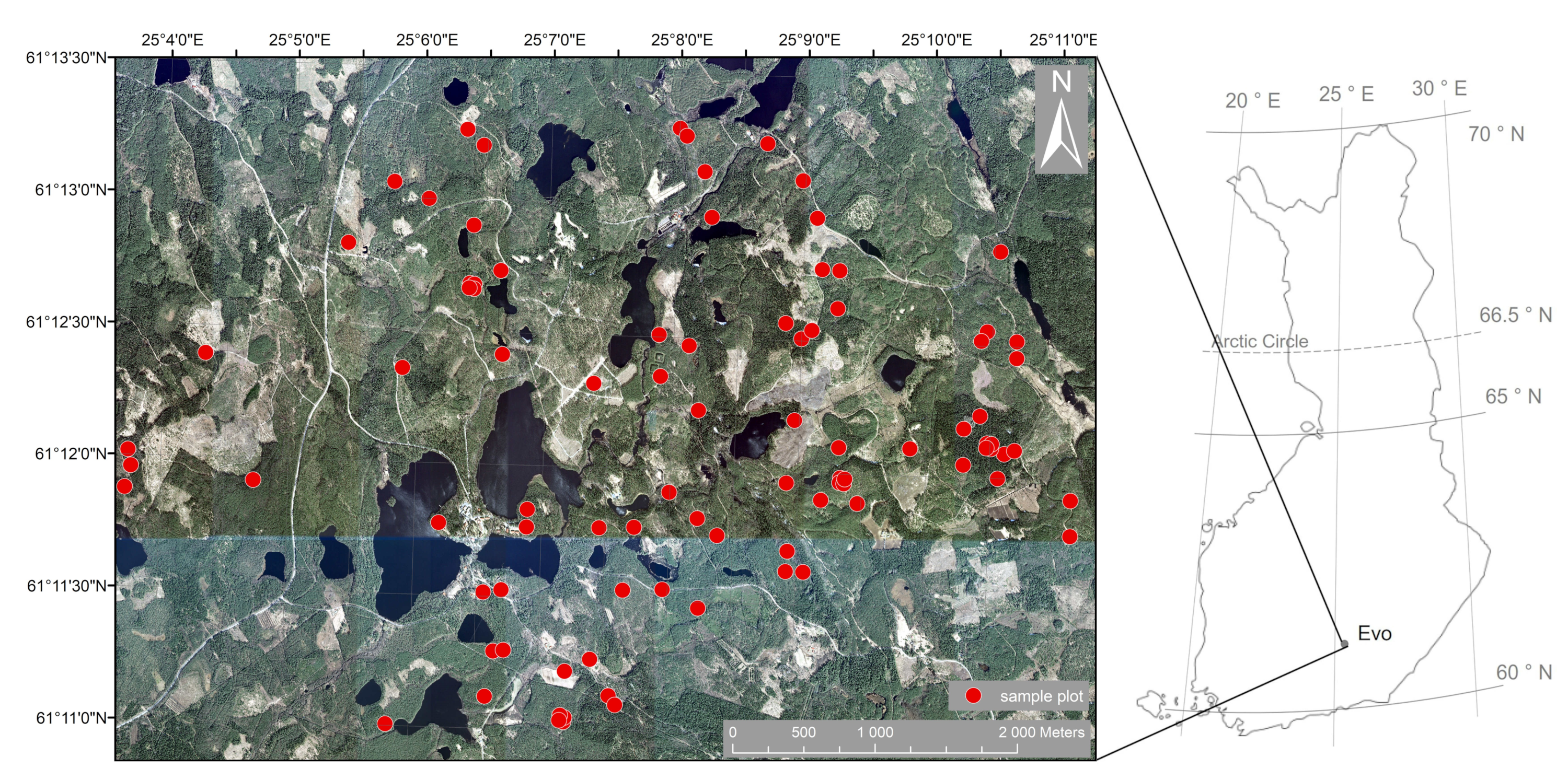
Figure 1. Map of the study area with sample plot locations on an orthophoto obtained in 2018 and provided by National Land Survey of Finland (licensed under CC BY 4.0).
Remotesensing 11 01423 g001
Figure 2. A 10 m × 10 m sub-sample of an original sample plot to illustrate the stage-one tree detection. First, a horizontal point cloud slice was delineated from the normalized point cloud (a). Then, points were segmented into clusters, and vertical and cylindrical point cloud structures were considered to represent cross-sections of trees (b).
Remotesensing 11 01423 g002
Figure 3. Extraction of the detected trees by generating a Voronoi diagram to define the closest tree for each point in the original normalized point cloud.
Remotesensing 11 01423 g003
Figure 4. An example of the stage-two tree detection. Multiple trees in a tree-wise point cloud (a) were detected using point cloud filtering and clustering. Stem points were extracted separately for both trees (b).
Remotesensing 11 01423 g004
Figure 5. Illustration of the scan set-up used in the terrestrial laser scanning (TLS) data acquisition. Colored small crosses (x) represent the locations of individual auxiliary scans with respect to the plot center of all the sample plots. Large plus-signs (+) represent the average location for each scan. Different-sized sample plots (radii of 6, 11, and 16 m) were used to assess the effect of the sample plot size to the accuracy and performance of the TLS-based approach in characterizing tree communities.
Remotesensing 11 01423 g005
Figure 6. Relationship between the measured and estimated forest inventory attributes when using different-sized circular sample plots with a fixed scan set-up.
Remotesensing 11 01423 g006
Figure 7. Relationship between stand heterogeneity and errors in the estimates for plot-level forest inventory attributes (aj).
Remotesensing 11 01423 g007
Figure 8. Variation in the correctness of tree detection and completeness in detecting the stem number (N), basal area (G), and volume (V) with respect to the sample plot size (a) and stand heterogeneity (be).
Remotesensing 11 01423 g008
Figure 9. Proportion of trees detected from TLS point clouds throughout the overall tree size distribution when using different-sized sample plots (i.e., plot radii of 6, 11, and 16 m). Bars represent the tree size class frequencies that are relative and scaled with respect to the total number of field-measured trees. Lines represent the respective tree detection rate within each class. To facilitate the comparison, the mean (µ) and standard deviation (σ) of the reference and TLS-based distributions are presented.
Remotesensing 11 01423 g009
Table 1. Summary of the sample plot data characteristics of previous studies where multi-scan terrestrial laser scanning data from several sample plots or large forest stands have been used for detecting and characterizing trees.
Study Site LocationNumber of PlotsPlot Size (m2)Stem Density 1 (n/ha)Reference
Finland241024381–2871[12]
Germany5707212–410[13]
Finland5314605–1210[14]
Switzerland9500200–800[15]
Spain / Mexico3500–600300–2100[16]
Finland / China71024366–2304[17]
Sweden71257~1241[19]
China8707~350[29]
Belgium10707114–1344[36]
Finland127,000~162[37]
Finland27300334–1167[38]
China391257-[39]
Finland101024342–1191[40]
Australia33300–1300153–570[41]
India41257400–500[42]
Austria140,800~438[43]
UK2200600–2800[44]
Finland51024507–928[45]
1 Variation in stem density between the sample plots (or mean density if variation in density is not provided).
Table 2. Characteristics of the field-inventoried 32 m × 32 m sample plots.
Forest Inventory AttributeMinimumMeanMaximumStandard Deviation
Dg (cm)13.925.846.47.5
Hg (m)10.021.131.14.4
G (m2/ha)6.626.943.27.9
N (n/ha)3429433076556
V (m3/ha)34.5271.5518.4110.7
Table 3. Workflow of the automatic point cloud processing method to obtain plot-level forest inventory attributes. For each stage, the main techniques and related parameters are presented.
StageTechniquesParameters
1.
Point cloud normalization
-
Point classification (ground/vegetation), DTM creation and point cloud normalization using lasground-tool from LAStools.
-
step 1
-
spike 0.4
-
bulge 0.5
-
offset 0.1
2.
Stage-one tree detection
-
Delineation of horizontal point cloud slice between hmin and hmax.
-
Point cloud filtering
-
Noise removal: Removal of points with average distance to k nearest points greater than one standard deviation from the mean of the average distance to neighbors among the k points.
-
Branch removal: Vertical surface delineation based on normal vector for surface formed by point and its n neighbor points. Removal of points with normal vector orientation deviating more than αmax from the horizontal direction.
-
Point cloud clustering: Segmentation of points into clusters with a minimum distance of dmin between the clusters.
-
Cylindrical structure finding: Fitting vertical RANSAC-cylinder into clustered points and removing outlier points.
-
Determination of tree locations through locations of clusters appearing as vertical cylinders with a radius ranging from rmin to rmax.
-
hmin = 1.1 m
-
hmax = 1.5 m
-
k = 20
-
n = 80
-
αmax = 0.15 °
-
dmin = 0.1 m
-
rmin = 0.025 m
-
rmax = 0.55 m
3.
Tree-wise point cloud extraction
-
Partition of point cloud based on a Voronoi diagram using tree xy-locations as seeds: Searching for the closest tree for each point.
-
Extraction of points representing the detected trees using a point-in-polygon approach.
4.
Stage-two tree detection
-
Delineation of stem points on vertical surfaces based on the normal vector orientation: Maximum allowed deviation of αmax from the horizontal direction.
-
Tree-wise point cloud clustering to find additional trees possibly missed by the stage-one tree detection.
-
Removal of clusters not representing tree stems by analyzing point cloud properties:
-
Height of the lowest point in cluster: hlow.
-
Height of the cluster: hcluster.
-
Number of points in cluster: ncluster.
-
Clusters fulfilling the conditions considered as tree stems.
-
αmax = 2.5°
-
hlow > 0.5 m
-
hcluster > 4 m
-
ncluster > 400
5.
Tree metrics extraction
-
Tree height:
-
Defined as the height of the highest point within a radius of rheight from the tree xy-location. For trees in lower canopy layers, searching for the top of the tree by investigating substantial gaps in the vertical point cloud distribution.
-
Taper curve:
-
Circle/cylinder fitting at different heights along the stem with hint intervals starting from the breast height (i.e., 1.3 m) and moving towards the stump and tree top.
-
Detection and removal of diameter-height observations defined as outliers:
-
Division of the stem into sections with length of lsection.
-
Removal of diameters deviating more than three median absolute deviations away from the median diameter of the section.
-
Comparison of diameters to the mean of the three previous (or three closest at the bottom of the stem) diameters. Considering diameter as an outlier if the relative difference exceeded thresholds, difbelow and difabove, for diameters below the breast height and above the breast height, respectively.
-
Cubic spline curve fitting using the smoothing parameter, p, to level unevenness in the filtered diameter measurements and to interpolate missing diameters at the top of the tree.
-
Tree volume:
-
Defined by using the Huber formula: considering the stem as a sequence of vertical cylinders with height of hcyl.
-
Derivation of diameters at the bottom and at the top of each cylinder using the stem curve. Estimation of the diameter at the middle of the cylinder as a mean of the diameters.
-
Computation of the cylinder volume as a product of the cylinder height and cross-sectional area in the middle of the cylinder (see Equation (6)).
-
Summation of cylinder volumes for a volume estimate for the entire stem.
-
rheight = 1 m
-
hint = 0.20 m
-
lsection = 2.5 m
-
difbelow = 20%
-
difabove = 10%
-
p = 0.5
-
hcyl = 0.1 m
6.
Plot metrics extraction
-
Stem number, basal area, and volume:
-
Defined as the sum of the single tree attributes, scaled for one hectare (Equations (1)–(3)).
-
Mean diameter and height:
-
Defined as the basal area-weighed mean of single tree attributes (Equations (4) and (5)).
Table 4. Root-mean-square-error (RMSE) and bias for the estimated forest inventory attributes when using different-sized sample plots with a fixed scan set-up. Relative figures are in parentheses, and negative bias denotes underestimation.
Plot SizeAccuracy MeasureDg (cm)Hg (m)G (m2/ha)N (n/ha)V (m3/ha)
r = 6 mBias−0.1
(−0.2%)
−0.5
(−2.4%)
−2.4
(−8.3%)
−235.1
(−23.5%)
−17.6
(−6.0%)
RMSE2.7
(10.6%)
1.6
(7.6%)
5.0
(17.6%)
459.0
(45.9%)
55.7
(19.1%)
r = 11 mBias0.3
(1.3%)
−0.6
(−2.8%)
−3.5
(−12.5%)
−281.6
(−29.2%)
−24.7
(−8.8%)
RMSE3.1
(12.3%)
1.3
(5.9%)
5.1
(18.4%)
498.3
(51.7%)
43.1
(15.3%)
r = 16 mBias0.5
(1.9%)
−0.9
(−4.2%)
−5.0
(−18.2%)
−349.4
(−36.4%)
−37.6
(−13.5%)
RMSE3.2
(12.3%)
1.3
(6.3%)
7.3
(26.4%)
596.1
(62.1%)
59.5
(21.3%)
32 m × 32 mBias0.8
(3.1%)
−1.1
(−5.0%)
−5.4
(−20.1%)
−369.0
(−39.1%)
−41.8
(−15.4%)
RMSE3.6
(13.8%)
1.5
(7.1%)
7.7
(28.5%)
613.7
(65.1%)
64.8
(23.9%)
Table 5. Overall accuracy in tree detection with respect to the sample plot size.
Sample Plot SizeCorrectness (%)Completeness (%)
NGV
r = 6 m93.071.190.893.4
r = 11 m93.666.288.391.3
r = 16 m94.159.883.286.6
32 m × 32 m93.957.080.684.1